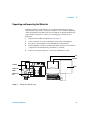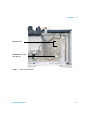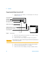
1
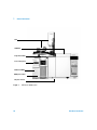
5975 Series Mass Selective Detectors Hardware Installation Agilent Technologies Notices © Agilent Technologies, Inc. 2010 No part of this manual may be reproduced in any form or by any means (including electronic storage and retrieval or translation into a foreign language) without prior agreement and written consent from Agilent Technologies, Inc. as governed by United States and international copyright laws. Manual Part Number G3170-90038 Edition Second edition, February 2010 Printed in USA Agilent Technologies, Inc. 5301 Stevens Creek Boulevard Santa Clara, CA 95052 Safety Notices CAUTION A CAUTION notice denotes a hazard. It calls attention to an operating procedure, practice, or the like that, if not correctly performed or adhered to, could result in damage to the product or loss of important data. Do not proceed beyond a CAUTION notice until the indicated conditions are fully understood and met. WA R N I N G Acknowledgements Microsoft® and Windows® are U.S. registered trademarks of Microsoft Corporation. 2 A WARNING notice denotes a hazard. It calls attention to an operating procedure, practice, or the like that, if not correctly performed or adhered to, could result in personal injury or death. Do not proceed beyond a WARNING notice until the indicated conditions are fully understood and met. Hardware Installation Contents 1 General Information Introduction 8 Important Safety Warnings 11 Many internal parts of the MSD carry dangerous voltages 11 Electrostatic discharge is a threat to MSD electronics 11 Many parts are dangerously hot 12 Hydrogen 12 Safety and Regulatory Certifications 14 Information 14 Symbols 15 Electromagnetic compatibility 16 Sound emission declaration for Germany Cleaning 17 Recycling the Product 17 Customer Responsibilities Before You Start 18 19 Other Documentation 2 16 20 Installation Overview 22 Unpacking and Inspecting the Materials Installing the GC 24 Connecting the Helium Lines to the GC Configuring the GC Hardware Installation 23 26 28 3 Conditioning the Column 29 Preparing the MSD for Installation Preparing the Vacuum System 30 31 Plumbing the Methane Line to the CI MSD Flow Module Connecting the MSD and the GC Installing the ChemStation PC 34 36 39 Verifying EI System Performance 40 Verify the tune performance 40 Verify the sensitivity performance 40 Switching from EI to CI Operating Mode Verifying CI System Performance Verify PCI performance 42 Verify NCI performance 42 42 Verifying High Mass System Performance Familiarizing the Customer 3 41 43 44 Checklists Installation Checklist 46 Verifying that site preparation is complete 46 Unpacking and inspecting the shipped materials GC installation 47 MSD installation 48 MSD ChemStation PC installation 50 Performance verification 50 Instrument Log Book updated 52 Customer Familiarization Checklist 53 Topics not included in familiarization Hardware overview 54 System operation 54 4 46 53 Hardware Installation MSD ChemStation software overview 54 MSD ChemStation software autotune descriptions Methods 55 Data acquisition 55 Data analysis 55 Sequence 56 MSD ChemStation maintenance 56 EI instrument user maintenance 56 Troubleshooting (Diagnostics) 57 Tune charts 57 Additional support information 57 Hardware Installation 54 5 6 Hardware Installation 5975 Series Mass Selective Detectors Hardware Installation 1 General Information Introduction 8 Important Safety Warnings 11 Safety and Regulatory Certifications 14 Cleaning 17 Recycling the Product 17 Customer Responsibilities 18 Before You Start 19 Other Documentation 20 This section provides information on how to identify specifically what type of MSD you are working with as well as how to properly clean and dispose of the instrument. Also included in this section are the “Important Safety Warnings” which list critical safety precautions for all users. Agilent Technologies 7 1 General Information Introduction This document provides installation instructions for the Agilent Technologies 5975 Series Mass Selective Detector (MSD). Installation must be performed by an Agilent Technologies service representative. The Agilent Technologies 5975 Series Mass Selective Detectors (MSDs) are diffusion and turbo pump MSDs. The 5975 Series MSD system consists of: NOTE Mix and match of the combinations below may not be supported. • 5975 Series MSD • Optional G3397A High Vacuum Gauge controller (required for CI operation) • Gas Chromatograph Series 6890 and 6850 Series GC, with options for MSD use 7890A Series GC, with options for MSD use 7820A Series GC, predefined bundles for the MSD use • ALS Autosamplers 7683 Series Automatic Liquid Sampler 7693 Series Automatic Liquid Sampler • Computer and MSD ChemStation software Refer to your MSD ChemStation documentation for additional information Table 1 lists possible configurations for the 5975 Series MSD. Figure 1 identifies many of the common parts. 8 Hardware Installation General Information Table 1 1 Available high vacuum pumps Model name Product number Description Ionization modes 5975C TAD VL MSD G3170A Diffusion Pump MSD Electron impact (EI) 5975C TAD inert MSD G3171A Standard Turbo MSD Electron impact (EI) G3172A Performance Turbo MSD Electron impact (EI) 5975C TAD inert XL MSD G3174A CI High Mass Performance Turbo Pump Electron impact (EI) Negative chemical ionization (NCI) Positive chemical ionization (PCI) 7820 VL MSD G3175A Diffusion Pump MSD Electron impact (EI) 7820 MSD G3176A Standard Turbo MSD Electron impact (EI) 5975C TAD inert XL MSD Hardware Installation 9 1 General Information ALS 7890A GC CI gas flow module Local control panel 5975 Series MSD MSD power switch GC power switch Figure 1 10 5975 Series MSD system Hardware Installation 1 General Information Important Safety Warnings Before moving on, there are several important safety notices that you should always keep in mind when using the 5975 Series MSD. Many internal parts of the MSD carry dangerous voltages If the MSD is connected to a power source, even if the power switch is off, potentially dangerous voltages exist on the wiring between the MSD power cord and the AC power supply, the AC power supply itself, and the wiring from the AC power supply to the power switch. With the power switch on, potentially dangerous voltages also exist on: • All electronics boards in the instrument. • The internal wires and cables connected to these boards. • The wires for any heater (oven, detector, inlet, or valve box). WA R N I N G All these parts are shielded by covers. With the covers in place, it should be difficult to accidentally make contact with dangerous voltages. Unless specifically instructed to, never remove a cover unless the detector, inlet, or oven are turned off. WA R N I N G If the power cord insulation is frayed or worn, the cord must be replaced. Contact your Agilent service representative. Electrostatic discharge is a threat to MSD electronics The printed circuit (PC) boards in the MSD can be damaged by electrostatic discharge. Do not touch any of the boards unless it is absolutely necessary. If you must handle them, wear a grounded wrist strap and take other antistatic precautions. Wear a grounded wrist strap any time you must remove the MSD right side cover. Hardware Installation 11 1 General Information Many parts are dangerously hot Many parts of the MSD operate at temperatures high enough to cause serious burns. These parts include but are not limited to: • The inlets • The oven and its contents • The detectors • The column nuts attaching the column to an inlet or detector • The valve box You should always cool these areas of the MSD to room temperature before working on them. They will cool faster if you first set the temperature of the heated zone to room temperature. Turn the zone off after it has reached the setpoint. If you must perform maintenance on hot parts, use a wrench and wear gloves. Whenever possible, cool the part of the instrument that you will be maintaining before you begin working on it. WA R N I N G Be careful when working behind the instrument. During cool-down cycles, the MSD emits hot exhaust which can cause burns. WA R N I N G The insulation around the inlets, detectors, valve box, and the insulation cups is made of refractory ceramic fibers. To avoid inhaling fiber particles, we recommend the following safety procedures: ventilate your work area; wear long sleeves, gloves, safety glasses, and a disposable dust/mist respirator; dispose of insulation in a sealed plastic bag; wash your hands with mild soap and cold water after handling the insulation. Hydrogen Hydrogen gas may be used as carrier gas, and/or as fuel for the FID. When mixed with air, hydrogen can form explosive mixtures. 12 Hardware Installation 1 General Information WA R N I N G When using hydrogen (H2) as the carrier gas or fuel gas, be aware that hydrogen gas can flow into the oven and create an explosion hazard. Therefore, be sure that the supply is off until all connections are made, and ensure that the inlet and detector column fittings are either connected to a column or capped at all times when hydrogen gas is supplied to the instrument. Hydrogen is flammable. Leaks, when confined in an enclosed space, may create a fire or explosion hazard. In any application using hydrogen, leak test all connections, lines, and valves before operating the instrument. Always turn off the hydrogen supply at its source before working on the instrument. WA R N I N G The MSD cannot detect leaks in inlet and/or detector gas streams. For this reason, it is vital that column fittings should always be either connected to a column, or have a cap or plug installed. When using hydrogen gas, check the system for leaks to prevent possible fire and explosion hazards based on local Environmental Health and Safety (EHS) requirements. Always check for leaks after changing a tank or servicing the gas lines. Always make sure the vent line is vented into a fume hood. Hardware Installation 13 1 General Information Safety and Regulatory Certifications The 5975 Series Mass Selective Detector conforms to the following safety standards: • Canadian Standards Association (CSA): CAN/CSA—C22.2 No. 61010–1–04 • CSA/Nationally Recognized Test Laboratory (NRTL): UL 61010–1 • International Electrotechnical Commission (IEC): 61010–1 • EuroNorm (EN): 61010–1 The 5975 Series Mass Selective Detector conforms to the following regulations on Electromagnetic Compatibility (EMC) and Radio Frequency Interference (RFI): • CISPR 11/EN 55011: Group 1, Class A • IEC/EN 61326 • AUS/NZ This ISM device complies with Canadian ICES-001. Cet appareil ISM est conforme a la norme NMB—001 du Canada. The 5975 Series Mass Selective Detector is designed and manufactured under a quality system registered to ISO 9001. Information The Agilent Technologies 5975 Series Mass Selective Detector meets the following IEC (International Electro-technical Commission) classifications: Equipment Class I, Laboratory Equipment Installation Category II, Pollution Degree 2. This unit has been designed and tested in accordance with recognized safety standards and is designed for use indoors. If the instrument is used in a manner not specified by the manufacturer, the protection provided by the instrument may be impaired. Whenever the safety protection of the 5975 Series Mass Selective Detector has been compromised, disconnect the unit from all power sources and secure the unit against unintended operation. 14 Hardware Installation 1 General Information Refer servicing to qualified service personnel. Substituting parts or performing any unauthorized modification to the instrument may result in a safety hazard. Symbols Warnings in the manual or on the instrument must be observed during all phases of operation, service, and repair of this instrument. Failure to comply with these precautions violates safety standards of design and the intended use of the instrument. Agilent Technologies assumes no liability for the customer’s failure to comply with these requirements. See accompanying instructions for more information. Indicates a hot surface. Indicates hazardous voltages. Indicates earth (ground) terminal. Indicates explosion hazard. Indicates radioactivity hazard. Indicates electrostatic discharge hazard. Indicates that you must not discard this electrical/electronic product in domestic household waste. Hardware Installation 15 1 General Information Electromagnetic compatibility This device complies with the requirements of CISPR 11. Operation is subject to the following two conditions: • This device may not cause harmful interference. • This device must accept any interference received, including interference that may cause undesired operation. If this equipment does cause harmful interference to radio or television reception, which can be determined by turning the equipment off and on, the user is encouraged to try one or more of the following measures: 1 Relocate the radio or antenna. 2 Move the device away from the radio or television. 3 Plug the device into a different electrical outlet, so that the device and the radio or television are on separate electrical circuits. 4 Make sure that all peripheral devices are also certified. 5 Make sure that appropriate cables are used to connect the device to peripheral equipment. 6 Consult your equipment dealer, Agilent Technologies, or an experienced technician for assistance. Changes or modifications not expressly approved by Agilent Technologies could void the user’s authority to operate the equipment. Sound emission declaration for Germany Sound pressure Sound pressure Lp <70 dB am according to EN 27779:1991. Schalldruckpegel Schalldruckpegel LP <70 dB am nach EN 27779:1991. 16 Hardware Installation General Information 1 Cleaning To clean the unit, disconnect the power and wipe down with a damp, lint-free cloth. Recycling the Product For recycling, contact your local Agilent sales office. Hardware Installation 17 1 General Information Customer Responsibilities The following are not included in the standard installation. They are the responsibility of the customer, unless previous arrangements have been made between the customer and the Agilent Technologies Customer Service Organization. • Preparation of all site facilities including the provision of adequate space, supporting bench, and power to match the unit(s) purchased. See the 5975 Series MSD Site Preparation Guide for details • Operating supplies: high-purity carrier and reagent gas(es), syringes, pipettes, vials, and solvents. See the 5975 Series MSD Site Preparation Guide for details • Installation and testing of additional detectors on the 6890 Series GC • Training for programs not specifically listed in this document • Tests of customer-supplied samples, equipment, and/or method development • Any tasks not described in this manual In addition, the customer is required to: • Provide someone to help lift the GC and MSD onto the bench • Have the primary user and, if possible, all other users of the MSD present during installation to receive familiarization instruction from the Agilent Technologies service representative 18 Hardware Installation General Information 1 Before You Start Verify that all the conditions specified in the 5975 Series MSD Site Preparation Guide have been met: • Adequate space is available for the MSD system • Suitable supporting bench • Adequate electrical power is available at the correct voltages and frequencies • Environmental control systems are adequate • Adequate preparations for safe exhaust venting • Supplies necessary for instrument operation are available, including solvents, helium carrier gas, and methane reagent gas (for CI MSDs) NOTE Installation and verification will only be performed using helium carrier gas. • Computer supplies, including diskettes and printer paper • Conveniently located telephone Lifting the GC and MSD will require the assistance of another person to prevent injury. Product Weight, kg Weight, lb G3171A Standard turbo pump 39 85 G3172A Performance turbo pump 41 90 G3174A CI High Mass performance turbo pump 46 100 6850 Series GC 23 51 6890 Series GC 50 110 7820A GC 50 110 7890A GC 50 110 5975 Series MSD Hardware Installation 19 1 General Information Other Documentation Additional information is contained in the following documentation: • 5975 Series Mass Selective Detector Hardware Manuals, which are located on the 5975 Series Mass Selective Detector User Information CD-ROM • 5975 Series Mass Selective Detector Site Preparation Guide • GC Series manuals • GC automatic liquid sampler documentation • GC accessories documentation • Agilent MSD ChemStation software manuals and online help • The sensitivity specifications for your instrument, Agilent publication 5988-9991EN • For updated information, see the Agilent Technologies Web site at http://www.agilent.com/chem 20 Hardware Installation 5975 Series Mass Selective Detectors Hardware Installation 2 Installation Overview 22 Unpacking and Inspecting the Materials 23 Installing the GC 24 Connecting the Helium Lines to the GC 26 Configuring the GC 28 Conditioning the Column 29 Preparing the MSD for Installation 30 Preparing the Vacuum System 31 Plumbing the Methane Line to the CI MSD Flow Module 34 Connecting the MSD and the GC 36 Installing the ChemStation PC 39 Verifying EI System Performance 40 Switching from EI to CI Operating Mode 41 Verifying CI System Performance 42 Verifying High Mass System Performance 43 Familiarizing the Customer 44 This chapter contains instructions for installing the 5975 Series MSD system. Agilent Technologies 21 2 Installation Overview Listed below are the steps performed for hardware installation. The actual order of the steps depends upon the type of MSD, GC, and accessory ordered. • Unpacking and inspecting shipped materials • Installing the GC • Installing the MSD • Installing the computer and peripherals • Integrating the GC and MSD • Evaluating performance • Familiarizing the customer with the system Installing CI MSD systems requires additional steps: • PFDTD calibrant added to calibration vial • Methane/isobutane gas purifier installation • Methane reagent gas line and gas purifier purge • Methane reagent gas line hookup After system performance has been verified in EI mode, the MSD must be switched to CI mode if applicable, and evaluated: • Chemical ionization (CI) ion source and CI interface tip seal installation • Bakeout and purge at least 2 hours • CI setup • Positive chemical ionization (PCI) autotune and sensitivity verification • Negative chemical ionization (NCI) autotune and sensitivity verification • High-mass autotune and sensitivity verification The G3397A High Vacuum Gauge controller is required for CI operation. 22 Hardware Installation Installation 2 Unpacking and Inspecting the Materials Shipping containers should not be opened until an Agilent Technologies representative is present to verify the contents of each container. Warranty claims for missing items will not be honored unless an Agilent Technologies representative verifies the contents of each shipping container as it is unpacked. 1 Unpack the GC, MSD, and PC boxes. See Figure 2. 2 Check each item off on the packing list, and verify serial numbers. 3 Record the serial numbers in the installation documentation. 4 Retain shipping containers and material until contents are checked for completeness and instrument performance is verified. 5 If there are any discrepancies, contact the distribution center. PC Monitor ALS tray Printer 5975 Series MSD 6890 Series GC Figure 2 Example GC, MSD, PC setup Hardware Installation 23 2 Installation Installing the GC Materials needed: Column cutter (5181-8836) Flat-blade screwdriver GC Series shipping kit Please refer to the GC/MS application note, “Optimizing splitless injections on your GC for high-performance MS analysis” (5988-9944EN) before installing the GC. 1 WA R N I N G NOTE 24 Place the GC on the bench. To prevent injury, get lifting assistance. 2 Remove the left side panel of the GC. 3 Remove the metal upper front knockout from the interior oven wall, using a flat-blade screwdriver (see Figure 3). 4 Do not remove the insulation between the exterior and interior oven walls, but move it aside. Use the screwdriver, not your fingers. 5 Pop out the two large plastic knockouts from the GC left side panel. 6 Reinstall the GC left side panel cover and route the GC end of the GC/MSD interface heater cable through the lower hole. The 7890 GC is shown here. The positions of the GC/MSD interface and heater cable will be slightly different depending upon the GC series used. Hardware Installation Installation 2 Metal knockouts GC/MSD interface heater cable (GC end) Figure 3 Removing the knockouts Hardware Installation 25 2 Installation Connecting the Helium Lines to the GC 1 Connect the 6-foot copper tubing (or a custom length) to the carrier gas supply line (Figure 4). Copper supply tubing On/Off valve Two-stage regulator Main supply On/Off valve Helium carrier gas supply Helium gas purifier (be sure the arrow points in the direction of gas flow) Copper supply tubing Figure 4 Connect helium CAUTION 26 2 Turn on the carrier gas flow at a low pressure, 35 to 55 kPa (5 to 8 psi). 3 Let the line purge for 5 to 10 minutes. 4 Connect the other end of the tubing to the input of the gas purifier. Only remove the caps in the gas stream or the gas purifier will be contaminated by air. This will ruin the gas purifier. 5 Connect one end of the copper tubing to the output of the gas purifier. 6 Let the line and gas purifier purge for 5 to 10 minutes. 7 Connect the other end of the tubing to the input of the EPC controller. Hardware Installation 2 Installation Purge the flow system for 20 minutes. You can continue with the next step while you wait. Hardware Installation 27 2 Installation Configuring the GC 1 If there is an ALS, install it now. Follow the instructions provided with the ALS. 2 CAUTION Install the Merlin Microseal (optional). Follow the instructions provided with the Merlin Microseal. Do not use syringes with tapered needles with a Microseal. 3 Connect the GC power cord to the appropriate electrical outlet. 4 Turn on the GC and verify that the GC passes self-test. Keep the GC oven turned off. 5 Configure the column parameters for the MSD column that is installed in the GC. On the GC keypad, select [Config] [Col 1] and configure the column for the GC Series that you have for the following parameters: Length (m) Diameter (µ) Film thickness Inlet Detector Vacuum correct Pres correct 28 6 Increase the supply pressure of the carrier gas to 50 to 60 psi. (This may be set higher, depending on the GC you are using). 7 Set the column flow rate to 5 mL/min and split flow to 200 mL/min. Hardware Installation Installation 2 Conditioning the Column 1 Remove the septum covering the free end of the GC column and cut about 1 cm off the end of the column. 2 Place the free end of the column into a beaker of solvent and check for bubbles to verify helium flow. Do not leave the beaker in the oven. 3 Set the inlet temperature to 300 °C. 4 Turn on the oven and ramp the oven temperature from 40 °C to 300 °C (or 10 °C above the maximum temperature used for your analysis) at 15 °C per minute. Hold for 10 minutes, then reset to 35 °C. While the oven is heating, proceed with the next steps. 5 Once the oven temperature exceeds 80 °C, inject 5 µL methanol into GC; repeat two more times at 5-minute intervals. This will help remove any contamination from the column before it is installed into the MSD. 6 When the temperature program is complete, set the inlet to 250 °C. 7 Turn the GC power off. Hardware Installation 29 2 Installation Preparing the MSD for Installation Materials needed: 5975 Series MSD Hardware Manual Tygon tubing or hose for pump exhaust (11-mm id) Wrench, 1/4-inch × 5/16-inch open end 5975 Series MSD Shipping Kit 5975 Series MSD CI Shipping Kit 1 WA R N I N G Unpack the MSD and foreline pump, and place them on the bench near the GC. To prevent injury, get lifting assistance. 2 Remove the analyzer cover of the MSD. See the 5975 Series MSD Hardware Manual for more information. 3 Equalize the pressure in the MSD by turning the vent valve knob counterclockwise 1/2 turn. The MSD is not under vacuum. It has been backfilled with clean, dry nitrogen for shipping. CAUTION The MSD is shipped with empty calibration vials. The MSD cannot be tuned without calibration fluid. 4 Add PFTBA (05971-60571) to the EI calibration vial at the front of the MSD. See the 5975 Series MSD Hardware Manual for more information. Special procedure for CI MSD 5 Add PFDTD (8500-8130) to the vial on the CI calibration valve. See the 5975 Series MSD Hardware Manual for more information. 30 Hardware Installation Installation 2 Preparing the Vacuum System Materials needed: 5975 Series MSD Hardware Manual Diagonal cutters Plastic gloves 1 Remove the plugs from the inlet and the outlet of the pump. 2 Verify that the available ac power matches the voltage rating of the foreline pump. 3 Attach the correct line voltage identification sticker to the MSD back panel. 4 Place the oil drip pan under the foreline pump as shown in Figure 5. Foreline hose (from high vacuum pump outlet) Exhaust outlet (use 11-mm id hose) Oil level window (sight glass) Oil drip tray Figure 5 5 Hardware Installation Preparing the vacuum system Remove the cable ties holding the foreline hose. 31 2 Installation 6 Remove the blank flange from the free end of the hose, and connect the hose to the inlet port of the pump. 7 If nontoxic and nonflammable carrier gas, solvents and analytes will be used, install the pump exhaust oil trap on the outlet of the pump. Otherwise, install a hose (11-mm id) to take the foreline pump exhaust outside or to a fume (exhaust) hood. Do not use the trap on a CI MSD. CAUTION Remove the red plug from the outlet of the pump before switching on the MSD power. Operation with the plug in place will destroy the pump. WA R N I N G The pump exhaust contains carrier gas and traces of solvents, analytes, and pump oil. The supplied trap stops only pump oil. It does not trap or filter out toxic chemicals. If you are using toxic solvents or toxic or flammable carrier gas, or analyzing toxic chemicals, vent the pump exhaust to a fume hood. 8 32 Connect the foreline pump power cord to the receptacle on the rear of the MSD. See Figure 6. Hardware Installation 2 Installation Remote start cable Transmit (Tx) and receive Power cord LAN cable Foreline pump power Power (PWR) and heartbeat (heart) LEDs Figure 6 Foreline pump power plug WA R N I N G The foreline pump must be plugged into the receptacle provided in the back of the MSD in order to have adequate overcurrent protection. Plugging the pump into a wall outlet will void the warranty on the pump. 9 WA R N I N G Install the optional G3397A High vacuum gauge controller (required for CI MSDs). Be sure not to stress the cable. The gauge controller must be properly grounded. See the manufacturer’s manual supplied with the gauge controller. Hardware Installation 33 2 Installation Plumbing the Methane Line to the CI MSD Flow Module Special procedure for CI MSD Refer to the 5975 Series MSD Hardware Manual. Materials needed: Methane supply with regulator Methane/Isobutane gas purifier (G1999-80410) Stainless-steel tubing, 1/8-inch Swagelok fittings and ferrules for 1/8-inch tubing Wrench, 7/16-inch open-end, two needed 34 CAUTION Only remove the caps in the gas stream, or the gas purifier will be contaminated by air. This will ruin the gas purifier. WA R N I N G Methane is flammable and explosive. Extinguish all sources of flame or spark in the room. Only perform this procedure in a well-ventilated room. Obey all local safety and environmental regulations. CAUTION Do not remove the Swagelok caps from the Gas A and Gas B inlets until you are ready to hook up the gas lines. 1 Install the methane/isobutane gas purifier. Follow the instructions on the gas purifier. 2 Set the pressure on the methane regulator to 20 psig (do not exceed 30 psig). 3 Connect one piece of the 1/8-inch, stainless-steel tubing to the methane supply regulator. 4 Turn on the gas flow slightly. 5 Connect the other end of the tubing to the inlet of the gas purifier. 6 Connect the second piece of stainless-steel tubing to the outlet of the gas purifier. Hardware Installation Installation 7 Let the lines purge into a fume hood for 5 to 10 minutes. 8 Connect the other end of the tubing to the Gas A fitting on the flow module as shown in Figure 7. 9 If another reagent gas is to be used, use more stainless steel tubing to connect it to the Gas B fitting. 2 If you are going to connect isobutane, you will need another gas purifier for the Gas B line. Observe the manufacturer’s suggested pressure settings. CAUTION Do not connect isobutane without a gas purifier. Do not use the gas purifier with ammonia. Gas A (methane) line Gas B (alternate reagent gas) line Figure 7 Connecting the methane line Hardware Installation 35 2 Installation Connecting the MSD and the GC 1 Verify that the GC power is turned off. 2 Connect the two ends of the GC/MSD interface cable as shown in Figure 8. GC/MSD interface cable 5975 Series MSD 7890 Series GC Figure 8 Connecting the MSD and the GC 3 36 Carefully position the MSD close to the GC as shown in Figure 8. Hardware Installation Installation 2 When positioned properly, the end of the GC/MSD interface cover will touch the metal of the oven wall, and the end of the interface will protrude into the GC oven. The sides of the GC and MSD should be parallel. Note that the end of the interface on a CI MSD will not protrude quite as far into the GC oven as that on an EI MSD. 4 Connect a remote cable between the MSD and one of the remote connectors on the back of the GC. 5 Connect the MSD power cord to an appropriate AC outlet. 6 Loosen the sideplate thumbscrews completely (shown in Figure 9) and open the analyzer. Rear sideplate thumbscrew (loosen completely) Figure 9 Loosen sideplate thumbscrews CAUTION 7 Remove the interface column nut and blank ferrule from the end of the GC/MSD interface. 8 Install the column in the GC/MSD interface. See the 5975 Series MSD Hardware Manual for more information. Opening the analyzer with either sideplate thumbscrew tight will irreparably damage the baseplate. Damage of this type is not covered by the warranty. 9 Turn the GC on. 10 Set the GC column flow to 1.0 mL/min with constant flow enabled. 11 Pump down the MSD. Hardware Installation 37 2 Installation Press on the side plate of the MSD to achieve a good seal. Verify that the foreline pump and the front fan turn on, and that the foreline pump stops gurgling within 1 minute. 38 12 After 10 minutes of pumping, turn off the MSD. 13 Turn off the GC temperature zones. 14 Set column flow to 1.0 mL/min with constant flow enabled. 15 Reinstall the MSD analyzer cover. Hardware Installation 2 Installation Installing the ChemStation PC 1 Unpack the PC, monitor, printer, and the modem (if present). 2 Position the PC components on the bench. 3 Install the PC. See the PC installation documentation. Please pay attention to the voltage requirements in the PC documentation. 4 Position the network switch on the bench, and plug in its power supply. See the switch installation documentation. 5 Connect a shielded LAN cable between the LAN connector on the MSD and connector #1 on the network switch. 6 Connect a shielded LAN cable between the RJ-45 connector on the back of the GC to connector #2 on the network switch. 7 Connect a shielded LAN cable between the RJ-45 connector on the back of the PC and connector #3 on the network switch. 8 Install the printer. See the printer installation documentation. 9 Turn on the printer, monitor, and PC, in that order. The switch does not have a power switch; it is “on” whenever it is connected to AC power. 10 Hardware Installation Install the software. See the software installation manual. 39 2 Installation Verifying EI System Performance Material needed: 1 pg/µL (0.001 ppm) OFN sample (5188-5348) Verify the tune performance 1 Verify that the system has been pumping down for at least 60 minutes. 2 Set the GC oven temperature to 150°C, and the column flow to 1.0 mL/min. 3 In the Instrument Control view, select Checkout Tune from the Checkout menu. The software will perform an autotune and print out the report. 4 When the autotune has completed, save the method, and then select Evaluation Tune from the Checkout menu. The software will evaluate the last autotune and print a System Verification – Tune report. Verify the sensitivity performance 1 Set up to inject 1 µL of OFN, either with the ALS or manually. 2 In the Instrument Control view, select Sensitivity Check from the Checkout menu. 3 Click the appropriate icons in the Instrument Edit window to edit the method for the type of injection. 4 Click OK to run the method. 5 When the method is completed, an evaluation report will print out. Verify that rms signal-to-noise ratio meets the published specification. See Agilent publication 5988-9991EN. 40 Hardware Installation Installation 2 Switching from EI to CI Operating Mode Special procedure for CI MSD Refer to the 5975 Series MSD Hardware Manual. CAUTION CAUTION 1 Vent the MSD. 2 Open the analyzer. 3 Remove the EI ion source. Electrostatic discharges to analyzer components are conducted to the side board where they can damage sensitive components. Wear a grounded antistatic wrist strap (see the 5975 Series MSD Hardware Manual) and take other antistatic precautions before you open the analyzer. 4 Install the CI ion source. 5 Install the interface tip seal. 6 Pump down the MSD. 7 Set methane flow to 40%. 8 Bake out and purge the MSD for at least 2 hours. 9 If the vacuum gauge controller is on, turn it off. 10 Set up the software for CI operation. Load PCICH4.U. 11 Select Purge Cal Valve from the Vacuum menu in the Tune and Vacuum Control view. Do not proceed without purging the calibration valve, or the analyzer will be damaged. 12 Set up the methane reagent gas flow. 13 Select the Tune/CI from the Tune menu to edit PCICH4.U as needed. 14 Perform the autotune. Select Tune/CI Tune. 15 Verify that there is no visible peak at m/z 32, and that the peak at m/z 19 is less than 50% of that at m/z 17. Hardware Installation 41 2 Installation Verifying CI System Performance Special procedure for CI MSD Refer to the 5975 Series MSD Hardware Manual. Verify PCI performance 1 Perform a positive CI autotune. See the 5975 Series MSD Hardware Manual. 2 Verify positive CI performance. See the 5975 Series MSD Hardware Manual. 3 Verify that rms signal-to-noise ratio meets the published specification. Verify NCI performance NOTE 42 1 Perform a negative CI autotune. 2 Verify negative CI performance. 3 Verify that rms signal-to-noise ratio meets the published specification. See Agilent publication 5988-9991EN. There are no criteria for a “passing” CI autotune. If the CI autotune completes, it passes. EMV at or above 2600 V, however, indicates a problem with the system, and will cause problems meeting the sensitivity specification. Hardware Installation Installation 2 Verifying High Mass System Performance Refer to the 5975 Series MSD Hardware Manual. To check high mass performance, the system makes 1 injection of the high mass checkout sample and analyzes the results. For high mass systems, verify high mass system performance as follows: 1 Load the high mass checkout method, PFHT.M, and resolve any configuration conflicts. 2 Load the high mass checkout sample into vial 2. 3 When the GC and MSD are ready, select Checkout/High Mass Check from the Intrument view. 4 Verify that the rms signal-to-noise ratio meets the specifications described in the 5975 Series MSD Hardware Manual. Hardware Installation 43 2 Installation Familiarizing the Customer Follow the “Customer Familiarization Checklist” on page 53. Important points about the CI MSD to cover include: Cleanliness is the most important factor for success in CI, especially negative mode. This includes air leaks, water, and residual PFDTD calibrant. NCI reagent gas setup: There are no negative reagent ions formed. To set up for NCI mode, tune in PCI mode, then load NCI tune file to switch parameters, set gas flow to 40%; adjust if necessary for specific analyte. NCI operation: Reagent gas flow, source temperature, and emission current are the three most important parameters for optimizing NCI. No PFDTD calibrant ions are formed in PCI with isobutane or ammonia. Tune with methane, and copy parameters to new file: for example, PCINH3.U. The gas purifier can not be used with ammonia. Must ballast foreline pump daily if running ammonia. Refer to the maintenance chapter of the 5975 Series MSD Hardware Manual. For updated information, see the Agilent Technologies Web site at http://www.agilent.com/chem. 44 Hardware Installation 5975 Series Mass Selective Detectors Hardware Installation 3 Checklists Installation Checklist 46 Customer Familiarization Checklist 53 This section provides a series of checklists which will help you verify your completion of the various steps of the installation process. Also included are checklists which are intended to aid you in becoming familiar with the system. Agilent Technologies 45 3 Checklists Installation Checklist Verifying that site preparation is complete Adequate space is available for the MSD system. Suitable supporting bench. Adequate electrical power is available at the correct voltages and frequencies. Environmental control systems are adequate to maintain a correct, stable operating environment. Safe exhaust venting preparations are adequate. Supplies necessary for instrument operation are available, including solvents, carrier and reagent gasses, and printer paper. Conveniently located telephone. Unpacking and inspecting the shipped materials Shipping containers must be opened only with an Agilent Technologies representative present to verify the contents of each container. Check each item off on the packing list and verify serial numbers. Record the serial numbers in the installation documentation. Retain shipping containers and material until contents are checked for completeness and instrument performance is verified. Notify the distribution center of any missing or damaged items. 46 Hardware Installation Checklists 3 Shipment damaged or incomplete: Distribution center notified (date): Person contacted: DM notified (date): Damaged or missing material: GC installation The following steps are general, and may differ slightly depending upon the series of GC used. GC placed on an appropriate bench Upper front knockout in the interior oven wall removed The two large plastic knockouts removed from the left side panel Left side panel reinstalled; GC/MSD interface cable routed through the rear hole Connecting helium lines to the GC Carrier gas supply plumbed with copper tubing Plumbing purged with helium at 35 to 55 kPa (5 to 8 psi) for 5 to 10 minutes Gas purifier plumbed and purged Hardware Installation 47 3 Checklists GC plumbed Configuring the GC ALS installed (optional) Merlin Microseal installed (optional) GC plugged in and turned on GC passes self-test Column parameters configured Carrier gas line pressure set to approximately 414 kPa (60 psi) Column flow rate set to 5 mL/min (split flow to 200 mL/min) Conditioning the column Free end of column trimmed Helium flow through column verified Inlet temperature set to 300 °C Oven temperature ramped from 40 °C to 300°C at 15 °C per minute and held for 10 minutes 5 µL of methanol injected into GC; repeated two more times at 5-minute intervals Inlet set to 250 °C GC power off MSD installation Preparing the MSD for installation MSD and foreline pump unpacked and placed on the bench MSD top cover removed Vent valve opened to equalize pressure PFTBA vial for EI cal valve filled 48 Hardware Installation Checklists 3 PFDTD vial for CI cal valve filled Preparing the vacuum system Plugs removed from the foreline pump Foreline pump line voltage verified to match available AC power Line voltage identification sticker installed on MSD Oil drip pan under the foreline pump Foreline hose connected to the pump Pump exhaust vented to a fume hood or the oil trap installed Foreline pump power cord plugged into MSD G3397A High Vacuum Gauge Controller installed (required for CI MSDs) Plumbing the methane line to the CI MSD Methane/isobutane gas purifier installed Regulator pressure set to 20 psig (do not exceed 30 psig). Gas purifier and lines purged Methane reagent gas lines plumbed to flow module Connecting the MSD and the GC GC power turned off GC/MSD interface heater cable connected MSD positioned with interface in GC oven Sideplate thumbscrews loosened completely; analyzer opened Column installed in the GC/MSD interface Remote cable connected between the GC and the MSD Foreline pump and AC supply power cords connected to the MSD. MSD plugged in MSD power on (press on the sideplate) Hardware Installation 49 3 Checklists Foreline pump and the front fan operation verified Foreline pump stops gurgling within 60 seconds verified MSD turned off after 10 minutes of pumping down GC heated zones turned off GC carrier gas flow set to 1.0 mL/min with constant flow enabled MSD ChemStation PC installation PC, monitor, and printer unpacked PC installed Network switch unpacked and plugged in LAN cable from the MSD connected to switch Port #1 LAN cable from the GC connected to switch Port #2 LAN cable from the PC connected to switch Port #3 Printer installed Printer, monitor, and PC turned on (in that order) Software installed per the software installation manual Performance verification EI system verification Pumpdown for at least 60 minutes GC oven set to 150 °C and the column flow to 1.0 mL/min Checkout Tune performed Tune Verification performed Sensitivity Check verification of EI Sensitivity performance Switch CI MSD to CI operating mode (if applicable) MSD vented 50 Hardware Installation Checklists 3 EI ion source removed CI ion source installed CI interface tip seal installed MSD pumped down and baked out for 2 hours Software set up for CI operation Purge Cal Valve performed Methane reagent gas flow set up Acceptable air and water background verified PCI performance verification (if applicable) PCI autotune performed PCI sensitivity verified NCI performance verification (if applicable) NCI autotune performed NCI sensitivity verified High Mass performance verification (if applicable) High Mass Checkout performed Hardware Installation 51 3 Checklists Instrument Log Book updated MSD serial number recorded on S/N report S/N Report(s) and Tune Report(s) faxed to GCMS LSCA Technical Marketing at (USA) 408-553-3188 or your region’s local Technical Marketing Support Provider 5975 Series MSD serial number/product number: EI serial number (rms): PCI serial number (rms): NCI serial number (rms): 52 Hardware Installation Checklists 3 Customer Familiarization Checklist The purpose of customer familiarization is to demonstrate the steps required to: • Perform a basic analysis using an Agilent standard sample or an internal data file • Evaluate the acquired data • Perform routine maintenance Much of the familiarization is accomplished while the hardware is being installed and checked out. For this reason, at least one operator must be present throughout installation and familiarization. Familiarization is intended to give operators a basic overview of the operation and maintenance of new instruments, systems, and applications software. It is not a substitute for a full operator training course. Topics not included in familiarization • Training on the PC, the mouse, Windows Operating System, DOS, Excel, Access, or any other Windows applications • Advanced mass spectral processing • Analysis of unknown samples • Analysis of customer standards or samples • Network setup of the MSD ChemStation with other PCs • Network setup of the MSD ChemStation with the building network • Methods development • Commands and their use in creating macros using a text editor • Customization of the system (including macro writing) • Executing a macro via methods (deuser.mac) or from the command line • Special macros • Any US EPA quantitation functions • Aromatic gasoline quantitation functions • Intelligent sequencing — Drug Analysis Acquisition • Any Drug Analysis quantitation functions Hardware Installation 53 3 Checklists Hardware overview MSD CI MSD (if applicable) Gas Chromatograph ALS (if applicable) Bar code reader (if applicable) PC hardware and peripherals System operation Switching on instruments, PC, and peripherals Starting Windows Operating System and using online help Starting MSD ChemStation software Switching between EI and CI operation (CI MSD only) MSD ChemStation software overview Software configuration of the instruments (MS Config) demonstrated EI/CI instrument configuration with MS Config demonstrated (if applicable) Different Quantitation Packages and how to switch between them demonstrated Views and menu structure demonstrated MSD ChemStation software autotune descriptions Various autotunes described Importance of retaining tuning records emphasized Ion source contamination, diagnosis of contamination, and use of control charts discussed EI autotune demonstrated and tune report explained 54 Hardware Installation Checklists 3 Manual tune explained View Tunes utility demonstrated and its importance explained PCI Autotune performed (if applicable) NCI Autotune performed (if applicable) Optimization of reagent gas and application dependency on gas flow, source temperature, and emission current discussed Importance of retaining tuning and maintenance records discussed Importance of backing up data, including tune files Methods Edit entire method demonstrated with OFN_SN.M, explaining the GC and MS Scan Parameters. Method save demonstrated Data acquisition Analytical method developed to run both scan and SIM Steps involved in acquiring data and editing an entire method described File designated to store the data; data file naming demonstrated Acquisition parameters saved as part of a method Use Scan/SIM (amu range 50:300/amu ion 272) on OFN for acquisition Snapshot demonstrated Data analysis Screen layout explained (TIC, spectral windows, command line, title bar, etc.) Loading data files demonstrated TIC, spectra, and extracted ion profiles demonstrated Integration performed and explained Hardware Installation 55 3 Checklists Library search (searching a spectrum) demonstrated Difference between standalone and online data analysis explained Sequence Sequence loading demonstrated Sample Log Table editing demonstrated Sequence saving demonstrated Running, halting, and position and run demonstrated MSD ChemStation maintenance Directory structure and maintenance of MSDCHEM files discussed Data backup options discussed Use of Windows Operating System DEFRAG and SCANDISK utilities discussed EI instrument user maintenance GC inlet, column installation and maintenance, flows, and parts replacement described MSD vent and pumpdown procedures performed and described using the ChemStation software Maintenance section of Hardware manual demonstrated Ion source cleaning demonstrated Electron multiplier horn replacement demonstrated Vacuum system preventive maintenance demonstrated EI Instrument User Maintenance GC inlet, column installation and maintenance, flows, and parts replacement described MSD vent and pumpdown procedures performed and described using the ChemStation software 56 Hardware Installation Checklists 3 Differences between the EI and CI source parts described Differences in installation and removal of the EI versus CI source described Maintenance section of Hardware manual demonstrated Ion source cleaning demonstrated Vacuum system preventive maintenance demonstrated; special precautions for certain reagent gases discussed Troubleshooting (Diagnostics) Tune charts under Qualify menu demonstrated Online help for troubleshooting demonstrated Tune charts Displaying results explained Ion Source parameters explained Mass Filter parameters explained Additional support information Use of manuals and online help explained Warranty and warranty enhancements explained Agilent Technologies Support services and how to obtain help explained Hardware Installation • Hardware • Software • Assist Packages • Additional Training • Consulting 57 3 Checklists Company name: Customer signature/date: Engineer signature/date: Sales order number: 58 Hardware Installation Agilent Technologies © Agilent Technologies, Inc. Printed in USA, March 2010 G3170-90002