1
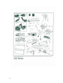
RAYPAK VERMONT LHEC30
GAS LOG FIREPLACE INSERT
Installation and Operating Instructions
For models LHEC30RFNAU (Nat Gas) and
LHEC30RFPAU (Propane)
1
CONTENTS
Part 1:
For Your Safety
Part 2:
Installation Instructions
•
•
•
•
•
•
•
•
•
•
•
•
•
•
•
•
•
•
•
•
•
Part 3:
Important Curing/Burning Instructions
Locating The Fireplace Insert
Fireplace and Trim Dimensions
Mantels
Framing and Finishing
Zero Clearance Applications
Gas Supply/Pipe Sizing
Gas Manifold Pressures
Preparing Appliance for Installation
Fan Kit
Fan Removal Instructions
Installation of Trim Switch for RN/RP Gas Valve
Fireplace Installation
Flue Installation
Chimney Liner Installation
Draft Relief Opening
Test Chimney Draw
Flue Safety System
Flue Safety Switch Access
Ceramic Refractory Installation
Wiring Diagram
Operating Instructions
• General Glass Information
• Louvre Removal
• Glass Cleaning
2
•
•
•
•
•
•
•
•
•
Part 4:
3
Glass Frame Removal
Log and Burner Lava Rock Installation
Large Lava Rock Placement
Flame Adjustment
Flame Characteristics
First Firing
Lighting and Operating Instructions
Troubleshooting – Gas Control
Instructions for RF Comfort Control Valve
Warranty
Part 1:
For Your Safety
For your safety do not operate this appliance before reading this
instruction book.
Warning: Improper installation, adjustment, alteration, service or
maintenance can cause injury or property damage. For assistance
or additional information consult with Raypak Australia, your
Raypak distributor, qualified installer or accredited Rheem
Australia Service Agency.
WHAT TO DO IF YOU SMELL GAS?
DO NOT try to light any gas appliance.
DO NOT touch any electrical switch.
Turn off gas supply at the meter.
Immediately call Rheem service or your gas supplier or licensed gasfitter.
Note: Some gases are heavier than air and it maybe necessary to check for gas
leaks at floor level.
CAUTION!
DO NOT operate this appliance before reading this instruction booklet.
DO NOT place articles or objects on or against the appliance.
DO NOT store chemicals or flammable materials in the same room as this
appliance.
DO NOT store chemicals or flammable materials on, or spray aerosols near this
appliance.
DO NOT operate with panels, covers or guards removed from the appliance.
FOR SAFE INSTALLATION AND OPERATION OF YOUR GAS
FIREPLACE PLEASE NOTE THE FOLLOWING:
a)
This appliance gives off high temperatures and should be located out of high
traffic areas and away from furniture and drapes/curtains.
4
b)
c)
d)
e)
f)
g)
h)
i)
j)
Children and adults should be altered to the hazards of high surface
temperatures of this appliance and should stay away to avoid burns or ignition
of clothing.
Children should be carefully supervised when they are in the same room as
the appliance.
Under no circumstances should this appliance be modified. Parts removed for
servicing should be replaced prior to operating this appliance again.
Installation and any repairs to this appliance must be carried out by a suitably
qualified and licensed service person. A professional service person should
be contacted to inspect this appliance annually. Make it a practice to have you
gas appliances serviced annually. More frequent cleaning maybe required
due to excess lint and dust from carpet, bedding material etc.
Control compartments, burners and air passages in this appliance should be
kept clear of dust and lint. Make sure that the gas valve and pilot light are
turned off before you attempt to clean this unit.
The appliance flue or chimney should be checked at least once a year and
cleaned if required.
Keep the area around your appliance clear of combustible materials, gasoline
and other flammable vapour and liquids. This appliance should not be used as
a drying rack for clothing etc.
Under no circumstances should any solid fuels (wood, coal, paper, cardboard
etc. be used in this appliance.
When the zero clearance kit is installed directly on carpet, vinyl tiles, linoleum
or any other combustible material other than wood, this heater must be
installed on a metal or wood base extending the full width and depth of the
heater. This insert cannot be installed directly onto or into combustible
materials.
Part 2:
•
Installation Instructions
Important Curing/Burning Instructions
Please read the following instructions carefully
It is normal for fireplace inserts fabricated of steel to give off some expansion and /or
contraction noises during the start up and cool down cycles.
It is not unusual for your Raypak LHEC30 Fireplace Insert to give off some odour the
first time it is lit. This is due to the curing of the paint and any undetected oil from the
manufacturing process.
Please ensure that you room is well ventilated and that all windows are opened
prior to lighting the appliance for the first time.
It is recommended that you burn your Raypak LHEC30 Fireplace Insert for at least
10 hours with the fan in the OFF position the first time you use it.
5
Locating Your LHEC30 Fireplace Insert with Zero Clearance Kit
Note: (Fig. 1) When you install you Raypak Fireplace Insert in (D) Room divider, (E)
Flat on wall corner positions or (F) Chase installation a minimum of 153mm
clearance must be maintained from the vertical wall to the outer edge of the trim.
•
Fireplace Insert Installations
Before installing the gas fireplace insert in a working fireplace, consideration must be
given to the functioning needs of the fireplace. The minimum fireplace opening
dimensions required for successful installation of this appliance is width 731mm x
height 534mm x depth 394mm. The design of the chimney for effective venting must
be determined. The availability of the gas supply as well as electricity must be
confirmed prior to the installation of this appliance.
This appliance is designed to be installed with a minimum vertical flue height
of 3.7m and a maximum vertical flue height of 10.7m.
6
•
7
Fireplace and Trim Dimensions
• Mantels
When the appliance is installed into a wood burning fireplace, the minimum distance
the mantel can be placed above the fireplace is governed by AS5601.
For applications requiring the use of a Zero Clearance Kit, the minimum height a
mantel can be installed above the fireplace is 610mm from the top of the upper
louvres. The maximum mantel depth is 200mm.
The underside of the mantel will become warm. Only use finishes that are heat
resistant and do not discolour.
•
Framing and Finishing
For zero clearance applications, it is important to determine the finished facing
material before beginning to frame. This will allow for the thickness of the finishing
material between the frame and the fireplace trim.
Consideration must also be given to the 25mm depth of the air inlet channel sitting
on the fireplace base. Finishing material for the hearth should be flush with the top of
the air inlet channel.
If the fireplace is installed at floor level a non-combustible hearth must extend a
minimum of 305mm in front of the fireplace.
If the fireplace is recessed into the wall and at least 305mm above floor level, no
hearth is required.
The use of wall paper adjacent to this fireplace is not recommended as high
temperatures given off by this appliance may adversely affect the binders in
the adhesive used to apply the wallpaper.
8
NOTE: Insulating around the fireplace will result in over heating and possible
malfunctioning of the circulating fan.
•
Zero Clearance Applications
Ensure that the room is adequately ventilated when this component is
installed.
For installations other than in existing wood burning fireplaces such as new
construction or renovation projects, a Zero Clearance Kit must be installed. The kit
enables these inserts to be installed in combustible environments. Whenever using a
Zero Clearance Kit consideration must be given to the dimensions of the Zero
Clearance Kit and the requirements of the Flue Kit.
Note: If a Zero Clearance Kit is required for the LHEC30 model only the Raypak
zero clearance kit HEZC must be used.
•
Gas Specifications
Model
LHEC30RFN
LHEC30RFP
9
Gas Specifications
Gas Type
Gas Control
Max. Input
Mj/h
Natural Gas
Comfort
32Mj/h
Control
Propane
Comfort
32Mj/h
Control
Min. Input
Mj/h
22.2Mj/h
23.7Mj/h
Gas Inlet and Manifold Pressures
Nat Gas
Minimum Inlet Pressure
1.1 kPa
Maximum Inlet Pressure
3.50 kPa
Manifold Pressure
0.87 kPa
•
Propane
2.75 kPa
3.50 kPa
2.50 kPa
Gas Type Conversion
Contact Rheem Spare parts in your State for gas type conversion kit and
instructions.
• Preparation for Installation
Before installation, remove glass door and logs from unit and check to make sure
there is no hidden damage to the unit.
• Gas Fitting Line Installation
Warning: When purging the gas fitting line, the front glass must be removed.
If gas fitting line has been previously completed, check that the gas fitting line is
of adequate size. Refer to Australian Standard AS5601 Gas Installations.
The gas fitting line can be installed through the rear or the base of the heater.
NOTE: When making the gas connection to the appliance inlet fitting, hold the
10mm 3/8” BSP fitting with a spanner when tightening the gas inlet pipe
compression nut.
For Propane installations an approved gas regulator must be fitted in accordance
with AS5601.
Ensure copper tube meets the requirements of Australian Standard AS1432
Type B.
•
Venting Installation
1. This fireplace insert may be installed in and vented through any solid fuel
fireplace that has a minimum opening of 730mm x 535mm x 395mm and has
been constructed and installed in accordance with state or local building
codes and is constructed of non-combustible materials.
2. In order to gain minimum gas insert fireplace opening requirement, if the fire
brick refractory is removed from a factory built fireplace, a minimum of 6mm
air space is required between the gas insert fireplace’s outer casing and the
inner wall of the factory built fireplace.
3. In order to gain the best performance, safety and efficiency for the LHEC30
Fireplace insert, the appliance must be installed with the approved 100mm
10
4.
5.
6.
7.
8.
(4”) diameter chimney liner. The Raypak chimney liner kit must be installed in
accordance with AS5601.
Any flue damper or blockage must be removed from the chimney prior to
installation of the insert.
The chimney must be clean and in good working order and constructed of
non-combustible materials.
Make sure that all chimney cleanouts fit properly so that air cannot leak into
the chimney.
Install the appliance without the trim frame and make all gas fittings and
electrical connections.
Install the decorative trim frame. Please refer to the frame assembly
instructions.
Warning: Installer must attach red warning plate with screws supplied with the
gas fireplace insert to the inside of the firebox of the fireplace into which the gas
fireplace insert is installed.
Warning: Cutting any sheet metal parts of the fireplace, in which the gas
fireplace insert is to be installed, is prohibited.
Warning: If the factory-built fireplace has no gas pipe access hole(s) provided,
an access hole of 40mm or less may be drilled through the lower sides of bottom
of the firebox. This access hole must be plugged with a non-combustible
insulation after the gas fitting line has been installed.
Warning: Some factory-built fireplaces have air passages on the face of the
fireplace for zero clearance capabilities. Under no circumstances should
these passages be blocked.
Zero clearance kit minimum clearance to combustible materials is 25mm (1”) for
twin skin flue. The use of single skin flue is not permitted for this type of
installation.
As with any natural draught appliance the end of the flue must be at least
500mm above the nearest part of the roof. Refer to AS5601 for details.
Warning: A minimum of 3.7m vent height is required to effectively vent this
appliance.
Common Flue Installation: In some installations it is possible to vent more than
one appliance into the same flue. You must ensure that the shared flue has the
proper capacity to adequately discharge the flue gases for the appliances using
the shared flue. Refer to AS5601.
•
Chimney Liner Installation
Insert liner from top of chimney through the damper opening and attach to the
100mm (4”) flue collar. For best results use three (3) sheet metal screws and a
hose clamp.
11
By packing non-combustible fibreglass insulation around the liner in the damper
area will isolate the fireplace cavity from the chimney and prevent draughts and
noises during operation.
In the case that the fireplace opening is only minimum height (533mm) and
access from the front is not possible, remove the flue collar plate – unscrew and
slide out from the back of the appliance. Now attach the liner to the flue collar, lift
up and slide the flue collar plate back onto the top of the unit. It is important that
the plate is completely inserted and the front screw is fastened again in order to
line up the flue outlet and the liner correctly. (Ref Fig. 11)
Warning: If the fireplace lintel is wider than 205mm (8”), the height of the
fireplace opening must be 635mm (25”) to allow for a 90° offset elbow to be
installed.
Fig. 11 Remove flue collar plate and attach to flue collar.
•
Draught Relief Opening
This insert is equipped with a draft-relief opening which receives its dilution air
supply through the opening at the back of the insert. These openings must not be
obstructed or entered in any way. (Ref Fig.12)
•
Test Chimney Draw
1. A “Chimney Draw” test must be conducted before the installation is complete.
2. Close all doors and windows in the home and start exhaust fans in the kitchen
and bathroom/s.
3. Light unit and operate for 5 minutes.
4. Hold an ignited match or candle in front of the unit. Refer to drawing number
Fig.12 for the location of the draught hood opening.
5. Check to make sure the smoke from the match or candle is drawn into the
fireplace. If it is not, turn unit off and check for causes creating the lack of
adequate draught.
12
•
Blocked Flue Shut Off System
These inserts are equipped with a blocked flue shut off switch. This switch is
factory fitted, wired and tested. Check to make sure the switch and wires are
in the correct position. The shut off switch is heat activated and wired in series
with the pilot system. (Ref Fig. 13)
Warning: Operation of this fireplace when not connected to a properly
installed and maintained flue or tampering with the blocked flue shut off
system can result in carbon monoxide (CO) poisoning and possible
death.
•
Blocked Flue Shut Off Switch Access
The shut off switch system of these inserts is designed to be accessed from
either inside the combustion firebox chamber or outside at the back of the
inserts fireplace.
1.
2.
3.
4.
Access to the shut off switch from the outside of the insert
Turn off the unit and let it cool down if it has been operating.
Shut off the gas and the power supply to the fireplace.
Disconnect the gas line and the draught hood of the fireplace.
Slide the fireplace out.
Access to the shut off switch directly from inside the combustion
firebox chamber.
1. Turn off the unit and let it cool down if it has been operating.
2. Remove the log set and remove the ceramic refractory if installed.
3. Remove firebox baffle (Ref Fig. 14)
13
4. Remove the shut off switch cover fastened with four (4) screws located at the
upper right corner of the firebox.
5. Now you can access the shut off switch assembly through the rectangular
opening. Remove the screw that secures the switch assembly. Holding the
bracket switch carefully, pull out the entire switch assembly.
NOTE: The shut off switch cover was attached with the gasket cover. Before
re-installing the gasket cover, inspect and make sure the gasket is not damaged.
If the gasket is damaged, install a new gasket.
•
Ceramic Refractory Installation (Optional)
1. Remove front glass.
2. Remove logs from heater.
3. Remove refractory from package.
Warning: Refractories are fragile and must be handled with care. Where at
all possible two hands should be used when handling.
4. Take centre refractory and tilt so that bottom edge seats onto the rear log
bracket at the back wall of the fireplace. (Ref Fig. 15)
5. Press centre refractory to back side of fireplace and hold in place.
6. Take left or right hand refractory and align it so leading edge faces outward.
(Place refractory in fireplace side and slide it back to support the centre
refractory.)
7. Repeat step 6 for remaining side refractory.
8. Fasten bracket supports against refractory top to hold side in place.
Warning: When side refractory is installed correctly, the centre refractory
will be supported by the side refractory.
14
Part 3:
Operating Instructions
NOTE: Carbon deposits may be present on the glass and logs. This is normal
and must be cleaned when the appliance is serviced or the glass door is cleaned.
Please refer to the General Glass Information section on page 15.
•
General Glass Information
Warning: Only ceramic glass approved by Raypak Australia may be
used for replacement on this unit.
1.
2.
3.
•
The use of substitute glass will void all product warranties.
Care must be taken to avoid breakage of glass.
Under no circumstances should this appliance be operated without
glass properly installed or with any cracked or broken glass.
Replacement of any glass assembly as supplied by the
manufacturer should be carried out by a suitably licensed and
qualified service person.
Louvre Removal
To remove louvre, lift louvre up and then pull out (Ref Fig. 16)
•
Glass Cleaning
It will be necessary to clean the glass periodically. During start up
condensation, which is normal, forms on the inside of the glass and causes
lint, dust and other airborne particles to cling to the glass surface. Initial paint
curing may deposit a slight film on the glass. It is therefore recommended that
the glass be cleaned two or three times with a non-ammonia household
cleaner and warm water. After this the glass should be cleaned two or three
times during each heating season or as required.
Warning: Clean glass after first two weeks of operation.
•
15
Glass Frame Removal
1.
2.
•
Log Installation and Burner Lava Rock
1.
2.
3.
a)
b)
c)
d)
e)
f)
•
Remove two (2) screws at the bottom of the frame. (Ref Fig.
17)
Lift up and unhook glass frame at the top.
Remove glass frame. (See “Glass Removal” section)
Remove logs from packaging.
Place logs according to the following instructions.
Place the rear centre log (KR24). Use the log’s bottom holes to
locate it onto the two (2) pin studs of the rear log bracket on the
centre.
Please rear left log (KR22). Use the log’s bottom holes to locate it
onto the two (2) pin studs of the rear log bracket on the left.
Place rear right log (KR23). Use the log’s bottom holes to locate it
onto the two (2) pin studs of the rear log bracket on the right.
Place the front left log (KR25). Position the log notch against the
second grate from the left and the other edge of the log on top of
the rear right log notch. Ensure the log is secure in place.
Place the front right log (KR26). Position the log notch against the
third grate from the right and the other edge of the log on top of the
rear right log notch. Ensure log is secure in place
Place the burner lava rock on the front area of the burner housing.
(Refer Fig. 19)
Large Lava Rock Placement
The large lava rock provided with this fireplace should be placed on the
firebox base on either side of the burner assembly.
16
Warning: Under no circumstances should these lava rocks be placed
on top of the burner assembly.
•
Flame Characteristics
It is important to periodically perform a visual check of the pilot and the
burner flames. Compare then to the drawings Figure 20, 21 and 22. If any
of the flame appear abnormal turn the appliance off and place a service
call.
•
First Firing
Upon completion of the gas line connection, a small amount of air will be in
the fitting line. When first lighting the pilot light it will take a few minute to
purge the air out of the system. Once the purging is complete, the pilot and
burner will light and will operate as indicated in the instruction manual.
Subsequent lighting of the appliance will not require such purging.
When lit for the first time, the appliance will emit a slight order for a short
period of time. This is due to the paints and lubricants used in the
manufacturing process. After each lighting, vapour may condense and fog
the glass, this moisture disappears within a few minutes of operation.
17
18
19
20
21
22
23
24
25
26
27
N
A
240V AC
Terminal Block
Fuse - 3 Amp
Transformer
240V AC - 110V AC
2A (50VA)
Speed Control
240V AC 50 Hz
Main Heater Supply
High Limit
Fan
LHEC30RFN/P WIRING DIAGRAM
28
Part 4:
Warranty
RAYPAK VERMONT LHEC30RFNAU & LHEC30RFPAU
GAS LOG FIREPLACE INSERT WARANTY
- AUSTRALIA ONLY –
Rheem Australia * will:
a) Repair or, if necessary replace any Raypak LHEC30RF Gas Log Fireplace Insert, or
b) Replace any component (or, if necessary, arrange the installation of a Raypak Gas
Log Fireplace Insert, which falls within the Warranty Periods specified below, in
accordance with and subject table, conditions and exclusions.
Installation
Models
From date of installation
Gas Log Fire
LHEC30RFNAU
Place Inserts
&
LHEC30RFPAU
Period
Year 1
Labour
Gas Log Fire
Place Inserts
Years 2
Parts
Fan and other components
Years 10
Parts
This warranty covers the appliance
heat exchanger for 10 years pro-rata
with a 1 year labour warranty.
Gas Log Fire
Place Inserts
LHEC30RFNAU
&
LHEC30RFPAU
LHEC30RFNAU
&
LHEC30RFPAU
Warranty
Notes:
* Rheem Australia Pty Ltd provides warranty service and spare parts on behalf of
Raypak Australia Pty. Ltd.
** Refer to item 5 of warranty conditions.
Rheem reserves the right to transfer fully functional components from the defective gas
log fire to the replacement gas log fire if required.
In addition to this warranty, the Trade Practices Act 1974 and similar laws in each state
and territory provide the owner under certain circumstances with certain minimum
statutory rights in relation to your Raypak gas log fire. This warranty must be read subject
to that legislation and nothing in this warranty has the effect of excluding, restricting or
modifying those rights.
Rheem Australia Pty Ltd
A.B.N 21 098 823 511
Raypak Australia Pty Ltd
A.B.N 65 078 743 414
29
FOR SERVICE TELEPHONE
131 031 AUSTRALIA
or refer to your local yellow pages
RAYPAK VERMONT LHEC30RFNAU AND
LHEC30RFPAU WARRANTY
- AUSTRALIA ONLY –
WARRANTY CONDITIONS
1.
2.
3.
4.
5.
6.
This warranty is applicable only to the LHEC30RFNAU and the LHEC30RFPAU
gas log fires manufactured from August 2005
The gas log fire must be installed in accordance with the Raypak installation
instructions, supplied with the appliance and in accordance with all relevant
statutory and local requirements of the State in which the appliance is installed.
This gas log fire must be correctly commissioned by a licensed and authorised
person and the installation certified by the relevant Gas Authority of the State in
which the appliance is installed.
Where a failed component or gas log fire is replaced under warranty, the balance
of the original warranty period will remain effective. The replaced part of gas log
fire does not carry a new warranty.
Where the gas log fire is installed outside the boundaries of the metropolitan area
as defined by Rheem or further than 25 km from a regional Rheem branch office,
or an accredited service agent, the cost of transport, insurance and travelling
costs between the nearest Rheem accredited Service Agent’s premises and the
installed site shall be owner’s responsibility.
The warranty only applies to the gas log fire and original or genuine (company)
component replacement parts and therefore does not cover any plumbing or
electrical parts supplied by the installer and not an integral part of the appliance.
Distributed By: RAYPAK AUSTRALIA PTY. LTD.
39 Koornang Rd
Scoresby Vic 3179
Ph:
Fax:
03 9757 3333
03 9757 3350
For Service and Spare Parts Call:
30
131 031