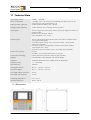
1
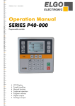
Operation Manual Series P40-000 Programmable controller LCD Display Simple handling Manual function Single set operation Program memory Digital outputs Analogue output 1 GENERAL INFORMATION ........................................................................................................................ 4 1.1 1.2 1.3 2 SAFETY................................................................................................................................................... 6 2.1 2.2 2.3 3 INFORMATION OPERATION MANUAL ............................................................................................................... 4 EXPLANATION OF SYMBOLS ............................................................................................................................ 4 STATEMENT OF WARRANTIES ......................................................................................................................... 5 GENERAL CAUSE OF RISK ............................................................................................................................... 6 PERSONAL PROTECTIVE EQUIPMENT ................................................................................................................ 6 CONVENTIONAL USE ..................................................................................................................................... 7 TRANSPORT AND STORAGE .................................................................................................................... 8 3.1 3.2 3.3 3.4 SAFETY INSTRUCTIONS FOR TRANSPORT/UNPACKING AND LOADING ...................................................................... 8 HANDLING OF PACKAGING MATERIAL .............................................................................................................. 8 CHECK OF TRANSPORT .................................................................................................................................. 8 STORAGE .................................................................................................................................................... 8 4 PRODUCT FEATURES .............................................................................................................................. 9 5 CONFIGURATION / FUNCTIONS ............................................................................................................ 10 5.1 ELEMENTS ................................................................................................................................................ 10 5.1.1 Control Elements ........................................................................................................................... 10 5.1.2 Display Elements (two‐axes‐version in the Program‐Mode is displayed here).............................. 10 5.1.3 Function of Keys ............................................................................................................................ 11 6 INSTALLATION / INITIAL OPERATION .................................................................................................... 12 6.1 MENU, SECTIONS AND PARAMETERS ............................................................................................................. 12 6.1.1 Axis Menu / Distances ................................................................................................................... 13 6.1.1.1 6.1.2 6.1.2.1 6.1.3 6.1.3.1 6.1.4 6.1.4.1 6.1.5 6.1.5.1 6.1.6 6.1.6.1 6.1.6.2 Distance / Longitudes Parameters............................................................................................................. 14 Axis menu / Times ......................................................................................................................... 18 Parameters of Time ................................................................................................................................... 19 Axis menu/analogue ..................................................................................................................... 20 Analogue Parameters ................................................................................................................................ 21 Axis menu/general parameters ..................................................................................................... 23 System Parameters .................................................................................................................................... 24 Reference....................................................................................................................................... 29 Functioning of the reference drive ............................................................................................................ 29 Menu / System .............................................................................................................................. 30 Menu / System Parameter ........................................................................................................................ 31 System‐Times ............................................................................................................................................ 33 6.2 FUNCTIONING OF THE INPUTS/OUTPUTS ......................................................................................................... 34 6.2.1 Functioning of the inputs............................................................................................................... 34 6.2.2 Functioning of the Outputs............................................................................................................ 35 6.3 CONFIGURATION OF INPUTS AND OUTPUTS ..................................................................................................... 37 6.3.1 Linking the Inputs with Functions .................................................................................................. 37 6.3.2 Assigning the Logic to Inputs ......................................................................................................... 37 6.3.3 Linking the Outputs with Functions ............................................................................................... 37 6.3.4 Assigning the Logic to Outputs ...................................................................................................... 37 7 OPERATION ......................................................................................................................................... 38 7.1 OPERATION MODES ................................................................................................................................... 38 7.1.1 Manual Mode ................................................................................................................................ 38 7.1.2 Single Mode ................................................................................................................................... 38 7.1.3 Program Mode .............................................................................................................................. 38 7.1.3.1 7.1.3.2 Entering a Program .................................................................................................................................... 39 Processing a Program ................................................................................................................................ 39 -2- 8 DIAGNOSTICS / ERROR SEARCH ............................................................................................................ 40 8.1 8.2 9 DIAGNOSTICS ............................................................................................................................................ 40 ERROR MESSAGE ....................................................................................................................................... 40 INTERFERENCE ..................................................................................................................................... 41 9.1 9.2 9.3 9.4 SECURITY .................................................................................................................................................. 41 ELECTRICAL INTERFERENCE SUPPRESSION ........................................................................................................ 42 RESTART AFTER FAULT CLEARANCE ................................................................................................................ 42 EMC INFORMATION ................................................................................................................................... 43 10 MAINTENANCE ................................................................................................................................. 43 11 TECHNICAL DATA ............................................................................................................................. 44 11.1 DIMENSIONS ............................................................................................................................................. 44 11.2 TABLES OF PARAMETERS .............................................................................................................................. 45 11.2.1 Parameter of axes ......................................................................................................................... 45 11.2.2 System parameter ......................................................................................................................... 46 11.3 TABLES OF I/O CONFIGURATION ................................................................................................................... 46 11.3.1 Mappings of the inputs ................................................................................................................. 46 11.3.2 Assignment of the outputs ............................................................................................................ 47 11.4 CONNECTOR PIN ASSIGNMENT ...................................................................................................................... 48 11.4.1 Overview connector pin assignment ............................................................................................. 49 11.5 EXAMPLE WIRING DIAGRAM ......................................................................................................................... 51 12 TYPE DESIGNATION .......................................................................................................................... 52 13 ACCESSORIES.................................................................................................................................... 53 -3- General Information 1 General Information 1.1 Information Operation Manual The manual contains important information regarding the handling of the controller. Precondition for safe operation is the compliance with the specified safety and handling instructions. Moreover, observe the existing local accident prevention regulation and general safety rules. Please read the operation manual carefully before starting to work. The manual is part of the product and should be kept accessible for the personnel near the device at anytime. The illustrations in the manual are for better representation of the facts; they are not necessarily to scale and can be slightly different to the actual construction. 1.2 Explanation of Symbols Warning notices Warning notices are characterized by symbols in the operation manual. The notes will be introduced through signal words to express the magnitude of the danger. Follow these advices in order to avoid accidents and injuries to persons and property. DANGER! This symbol in connection with the signal word „Danger“ indicates an immediate danger for the life and health of persons. Failure to heed these instructions can result in serious damage to health and even perilous injury. WARNING! This symbol in connection with the signal word „Warning“ indicates a possible danger to the life and health of persons. Failure to heed these instructions can result in serious damage to health and even fatal injury. ATTENTION! This symbol in connection with the signal word „Caution“ indicates a possibly dangerous situation. Failure to heed these instructions can lead to minor injury or property damage. Specific safety instructions: DANGER! This symbol in connection with the signal word “Danger” indicates an immediate danger for the life and health of persons through electricity. Failure to heed these instructions can result in perilous injuries or death. The operations have to be carried out only by an electrician. -4- General Information Tips and recommendations: NOTE! Here you can see highlights, useful tips, information recommendations for efficient and interference-free operation. and 1.3 Statement of Warranties The warranty conditions are in a separate document in the sales documents. Guarantee The producer guarantees the functional capability of the process engineering and the selected parameter. The period of warranty is one year and begins with the date of delivery. Dismounting and disposal Unless agreements on redemption and disposal have been made, demount and dispose the device environmentally compatible taking into account the security instructions of this manual. Before dismounting Disconnect the power supply and secure against re-start, then disconnect supply lines physically and discharge remaining energy. Remove operating and auxiliary materials. Disposal Recycle the decomposed elements: Collect metal scrap Electronic components in electronic scrap Recycle plastic parts Dispose the rest of the components according to their material consistence ATTENTION! Wrong disposal causes damage to the environment! Electronic waste, electronic components, lubricants and operating supplies are liable to treatment of hazardous waste and only approved specialized companies should perform disposal. Local authorities and waste management facilities provide information about environmentally suitable disposal. -5- Safety 2 Safety 2.1 General Cause of Risk This chapter gives an overview about all important safety aspects to guarantee an optimal protection of employees as well as a safe and transference-free operation. Non-observance of the instructions mentioned in this operation manual can result in hazardous situations. 2.2 Personal Protective Equipment Employees should wear protective clothing during installation of the device to minimize the risk of accidents. Therefore: Change into protective clothing before beginning the work process. Also observe any labels in the operating area regarding protective clothing. For all works, generally wear: Safety working clothing ... is close-fitting and tear-proof working clothing with tight sleeves and without distant parts. It serves to protect against being gripped by movable machinery parts. Also wear no rings, necklaces or other jewellery. Safety gloves ... for protecting the hands against abrasion and cuts. -6- Safety 2.3 Conventional Use The controller P40 is for the limited purpose as described in this manual: CAUTION! Danger through non-conventional use! An ELGO position control of the series P40 is not a safe control in the sense of the norm EN 61508. Safety-relevant shutdowns like emergency stop cannot be realised with the controller. Non-intended use and non-observance of this operation manual can lead to dangerous situations. Therefore: Use P40 only as described Strictly follow this manual Avoid in particular the following uses, they are considered as nonconventional: Remodelling, refitting or changing of the devi ce or parts of it with the intention to alter the functionality or the scope of the position controller. Demand due to damage from non-intended use is excluded. The operator is liable for all damages during non-conventional use. -7- Transport and Storage 3 Transport and Storage 3.1 Safety Instructions for Transport/Unpacking and Loading ATTENTION! Professional transport only. Do not throw, hit or fold the package. 3.2 Handling of Packaging Material Adverts for proper disposal refer to chapter General Information. 3.3 Check of Transport Examine delivery immediately after receiving for completeness and transport damages. In case of externally recognizable transport damages: Do not accept the delivery or do accept under reserve Note extent of damages on the transportation documents or on the delivery note Initiate complaint immediately INFORMATION! Claim any damages you recognize as soon as possible. The claims for damage can only be asserted in the lawful reclaim periods. 3.4 Storage Store device only under following conditions: Do not store outside Keep dry and dust-free Do not expose to aggressive media Protect from direct sun light Avoid mechanical shocks Storage temperature: -20 to + 50 °C Relative humidity: max. 60% Inspect packages regularly if stored for an extensive period of time (> 3 months) -8- Product Features 4 Product Features Essential features: Single or Two Axis-Controller Analogue or digital outputs for 1 - 3 speed operation 16 free programmable digital in-/outputs (optional 8 digital in-/outputs) Program memory for up to 1000 sets General: The single axis controller of P40 series is applicable to easy positioning tasks. An important feature is the easy structured function menu. It allows a quick and comfortable setting of the target value, if necessary a specific quantity of desired pieces. Target and actual value of the axes plus quantity will be displayed on the front panel. The keyboard is simple and user-friendly. With the keyboard the target and the actual value can be forced and the positioning can be started. The P40 series has an internal program memory for up to 1000 lines. For the positioning two different kinds of output signals are available: Switch mode positioning and PID-analogue output. The P40 series can alternatively be supplied with 24VDC. Basic modes of operation: The P40 consists of three general operation modes: Manual: Inching operation moves the axes through operating the keypad. Single: A whole set can be processed. Program: In the program mode data sets can be strung together or programmed. This set of records is then processed sequentially. The program consists in this case of several different data sets. -9- Configuration / Functions 5 Configuration / Functions 5.1 Elements 5.1.1 Control Elements Escape Menu Navigation Operation Mode Function keys Start Input 5.1.2 Stop Display Elements (two-axes-version in the Program-Mode is displayed here) Program Number Set Number Symbol operating mode Absolute / Incremental Position Actual Value Target Value Auxiliary Function Counter Program-Counter Page through the data sets ADVICE! Display elements can vary depending on control mode and configuration. - 10 - Configuration / Functions 5.1.3 Function of Keys Change Operation mode between „Manual“ and „Single“ Operation Mode “Program” (only at activated program mode) Activating (pressing 3 sec.) or exiting the Operation Mode or a Sub menu. Select or Confirm Cursor navigation „up“ Cursor navigation „down“ ... Function keys (addicted to Menu or Operation mode) Clear or reset an input Change of Sign ... Enter Target Value or Parameter value Start Positioning Stop Positioning - 11 - Installation / Initial Operation 6 Installation / Initial Operation 6.1 Menu, Sections and Parameters Operating Modes Manual Mode Single Mode Program Mode Service (press 3 sec the “ESC-Key”) Parameter axis X-axis System Distances Times Analogue (only with Option PID ) General Parameter Y-axis (only with 2 axes- version) Distances Times Analogue (only with Option PID ) General Parameter Settings System-times I/O-configuration Input function Input logic Output function Output logic Default parameter Password Diagnosis Input Output Keyboard Version INFORMATION! The service operation/parameter level can be reached by holding the “ESC” button for about 3 seconds. Most of the parameters, if not otherwise designated can only be changed after entering the password/ PIN code. PIN CODE: 250565 - 12 - Installation / Initial Operation 6.1.1 Axis Menu / Distances Relevant distances for the axes can be set in this menu. Axis distances Access to parameters concerning distances e.g. speeds etc. Axis times Access to parameters concerning times e.g. position reached, zero speed monitoring, rotary encoder etc. Axis analogue Access to parameters concerning the analogue output. Axis settings Access to general parameters concerning the axes. Slow forward Creep forward Correction stop forward Slow backward Creep backward Correction stop backward Tolerance window Manipulation Spindle compensation Forced loop Reference value Retract length End position Min End position Max Factor Displacement Tool correction - 13 - Installation / Initial Operation 6.1.1.1 Distance / Longitudes Parameters Slow forward/slow backward = middle speed This parameter serves the input of the distance, at which the controller switches from high speed to slow speed before reaching the target position. Creep forward/creep backward = slow speed This parameter serves the input of the distance, at which the controller switches from slow speed to creep speed before reaching the target position. Correction stop forward/correction stop backward Here a constant overrun can be compensated. Example: The target position is overrun by 0.2 mm constantly. The data entry has to be 0.2mm. The stop command is then moved forward by 0.2 mm. When starting the operation the stop offset is set first to "0" in order to be able to calibrate the overrun accurately. For an exact positioning the stop offset should be as small as possible (0.0 to 0.2 mm) i.e. the mechanical friction should be steady over the entire run distance and the slow speed and/or creep speed must be adjusted accordingly small. INFORMATION! When positioning with PID, the correction stop serves as tolerance window. - 14 - Installation / Initial Operation Example: Positioning with two speeds For the adjustment of the parameters generally applies: Slow speed = Creep speed > Correction stop Slow speed: Creep speed: Correction stop: 10,0mm 10,0mm 1,0mm Fast Position reached: 100,0mm Slow speed/Creep speed Correction Stop Slow 99,0mm 90,0mm 100,0mm Example: Positioning with three speeds Here for the adjustment of the parameters generally applies: Slow speed > Creep speed > Correction stop Slow speed: Creep speed: Correction stop: 20,0mm 10,0mm 1,0mm Fast Slow speed Position reached: 100,0mm Creep speed Correction Stop Slow Middle 80,0mm 90,0mm - 15 - 99,0mm 100,0mm Installation / Initial Operation Tolerance window If the current actual position of the target position corresponds + / - to the value of "tolerance window", the corresponding output "tolerance zone" (see the main configuration) is set. Manipulation It is possible to adjust the indicator of the actual value of the corresponding axis to the target value within the entered tolerance window. The entered range of tolerance is always active in the + and – range around the demand value. The real actual value is saved in the processor, i.e. no positioning errors add up. Example: Entered Value = 0,2mm (i.e. Tolerance Window +/- 0.2mm) Internal actual value Displayed actual value Target Value 99.8mm 100.0mm 100.0mm INFORMATION! The tolerance window should be set to zero before starting to operate. Spindle compensation In order to adjust spindle or sprocket tolerances the target position must always be approached from the same direction, i.e. in one direction the target position will be overrun by the entered value. After expiration of the time that was entered in menu/times/backlash dwell the entered target position will be reached again. Forced loop If the actual value is within the range target value +/- value of forced loop window during an absolute positioning a forced loop is moved. Reference value A reference value and a reference position can be forced in this parameter. Retract length When activating the external retract input, the axis moves depending on the retract mode (see 6.1.4.1 System parameters Æ Retract Mode) around this value or on this value. - 16 - Installation / Initial Operation Software-end position minimum/maximum These two values can be used if no mechanical switch end-positions are present or additionally for already existing mechanical switch end-positions. End position min.: This value should be between the smallest length/position that has to be proceeded and zero (respectively shortly before the mechanical switch end-position). End position max.: This value should be between the largest length/position that has to be proceeded and the maximum length (respectively shortly before the mechanical switch end-position). Factor The factor for analysis of the pulses is set here. INFORMATION! As of the Software Version 1.64 the decimal point (number of positions after decimal point) is calculated automatically. The controller has 4-edge-triggering! Displacement (no PIN necessary) Here positive or negative dimensions are programmed, which are added to the actual value by activating an allocated input. Tool correction (Saw blade) (no PIN necessary) In the incremental measurement mode this correction value is automatically added, i.e. the positioning process continues working off to this value - 17 - Installation / Initial Operation 6.1.2 Axis menu / Times The times relevant for the respective axis can be entered here. Axis distances Access to parameters concerning distances e.g. speeds etc. Axis times Access to parameters concerning times e.g. position reached, zero speed monitoring, rotary encoder etc. Axis analogue Access to parameters concerning the analogue output. Axis settings Access to general parameters concerning the axes. Position reached Spindle compensation Manual change Monitoring Delay Control enable Start delay Shutdown control Retract time Reference time Quantity reached - 18 - Installation / Initial Operation 6.1.2.1 Parameters of Time Position reached The output signal is based on a variable time during input of a time value or statically/maintained (axis in position) if the value is set to 0. It is set if the according axis has reached the target position. Spindle compensation In the peak of the loop drive, the drive signals decline. The controller returns to the target value when the parameterized time has expired (adjustment range 0.0 sec. … 99.9 sec.). If the value is zero, there is no waiting period at the peak. Manual change Here the time in manual mode can be entered to set the speed from the low speed to the next higher speed. Monitoring Here a time (adjustment range 0.0 sec. ... 99.9 sec.) is set to monitor the measurement system. If there are no signals from the measuring system during the programmed period of time, the drive signals are switched off to stop the engine. If the value is zero the monitoring is deactivated. Delay control enable After the start command the output “control enable” is activated. After reaching the target position and only after the expiration of the programmed time (adjustment range 0.0 sec. … 99.9 sec.) in the parameter “fall delay time control enable” the output is set back. If the parameter “delay control enable” is at the value of zero, the output for the control enable is adjusted statically and remains set until a change of operation modes respectively until activating the stop key. Start delay At a starting command the start of the positioning is delayed for the entered time. Shutdown control Here the time for shutdown after the position is reached is entered (adjustment range 0.0 sec. ... 99.9 sec.). Retract time The dwell-time at the peak is entered here (adjustment range 0.0 sec. …99.9 sec.). After this time the position control is set back from the retract peak to the target value. In addition this value is also used for a retraction on time. Reference time In the peak of the reference run, the drive signals decline. The controller will continue positioning when this time has expired (adjustment range 0.1 sec. ... 99.9 sec.). Quantity reached Here the time is entered in 0.1 sec. for the signal “quantity reached”. If the value = 0, the output “quantity reached” is statically set. - 19 - Installation / Initial Operation 6.1.3 Axis menu/analogue The axis relevant analogue parameters can be set in this menu. Axis distances Access to parameters concerning distances e.g. speeds etc. Axis times Access to parameters concerning times e.g. position reached, zero speed monitoring, rotary encoder etc. Axis analogue Access to parameters concerning the analogue output. Axis settings Access to general parameters concerning the axes. Velocity Acceleration P-Portion I-Portion D-Position I-Limit Impulses encoder Stop mode Manual fast Manual slow v Reference mode 1 v Reference mode 2 INFORMATION! The parameters for analogue mode are only of interest for devices with option PID. - 20 - Installation / Initial Operation 6.1.3.1 Analogue Parameters Velocity The maximum speed is set in this parameter, in rpm. Should there be gearing between the motor and the measuring system, this has to be considered in the calculations (e.g. gear or spindle) Example! Demanded (below the maximum possible !) motor speed rpm = 3000 Gearing ratio i = 10 V = rpm/i = 3000 rpm/10 = 300 rpm Acceleration The acceleration during positioning is set in this parameter in revolutions per square second ( [U ] ). [s 2 ] Also here you have to consider possible gearing ratio. P-Portion Proportional amplification: setting range 1 ... 99999 General: The P-controller exclusively consists of a proportional portion and has thereby its reinforcing characteristic. The P-term multiplies the input value with a constant coefficient. P40: At offset the difference between the target and actual value is multiplied with the entered value and shown as power-sharing. The bigger the proportional amplification the more sensitive the control loop will be (possibly even unstable). I-portion / I-Limit Integral step: setting range 1 ... 99999 General: An I-controller (integrating controller) determines the control value through timed integration of the offset taking the reset time into account. A continuing offset leads to further increase of the analogue output. The reset time determines how big the temporal influence is. The maximum reset time is limited through I-limit. The step response of the I-portion is a linear increase. That means for a constant offset the integral will be increased and thus reinforces the I-portion. P40: At offset the analogue control voltage will continue to increase step by step until there is zero difference between the target and actual position and the entered I-limit in this parameter is reached respectively. The greater the I-portion, the slower is the response. - 21 - Installation / Initial Operation D-portion Differential voltage: setting 1...1000 General: The D-controller (differential controller) determines the control value from the derivative with respect to time of the offset. P40: At offset a short voltage pulse proportional to the rate of change will be put out to compensate quickly without sacrificing the stability of the control loop permanently. The value of the voltage pulse is entered. (max + / - 10 V). Impulses encoder (rotary encoder resolution) The number of pulses per revolution of the engine is entered in this parameter. This enables amongst others the calculation of speed to be effected (max. 9999 pulses per revolution). Stop mode Mode Value 0 the voltage of the analogue output is set to 0V 1 the drive is set to shutdown through the highest possible acceleration 2 the drive is set to shutdown through an acceleration according to the adjusted parameter Manual fast Here the speed “fast” for moving the axis in manual mode can be defined. Manual slow Here the speed „slow“ for moving the axis in manual mode can be defined. v Reference mode 1 Here the reference run speed of the stopping point until reaching the initiator is defined. v Reference mode 2 Here the reference run speed of stopping point until reaching the index pulse is defined. - 22 - Installation / Initial Operation 6.1.4 Axis menu/general parameters System relevant general parameters can be entered in this parameter. Axis distances Access to parameters concerning distances e.g. speeds etc. Axis times Access to parameters concerning times e.g. position reached, zero speed monitoring, rotary encoder etc. Axis analogue Access to parameters concerning the analogue output. Axis settings Access to general parameters concerning the axes. Axis type Button manual mode Drive signal configuration Reference mode Spindle compensation mode Software end-position Hardware end-position Retract mode Error compensation Counter Incremental positioning Decimal point Display option manual Display option unit - 23 - Installation / Initial Operation 6.1.4.1 System Parameters Axis type The type of axis is defined. Digital + CPU (use with positioning through digital drive signals) Digital + PID (use with PID version) Button manual mode The function of the keys in manual mode is defined in this parameter. off (The buttons F1, F3 on the control are deactivated for the according axis. This axis can only be moved via the correspondingly assigned inputs.) normal inverted Drive signal configuration With configuration of the drive signals different starting combinations for the corresponding speeds can be adjusted. Drive signals Æ Mode 1 3 speeds Speed = output signals 1-3 ascending Output 4 sets direction reverse Output signals Creep forward Slow forward Fast forward Creep backward Slow backward Fast backward 1 X X X X X X 2 3 X X X X X 4 X X X X Drive signals Æ Mode 2 2 speeds ((ELGO Standard) Independent outputs for forwards and reverse Independent outputs for fast and slow Output signals Creep forward Slow forward Fast forward Creep backward Slow backward Fast backward 1 X 2 X X 3 4 Signal configuration: X Forwards: Creep speed: Fast speed: Backwards: X X X X - 24 - Drive signal 1 Drive signal 2 Drive signal 3 Drive signal 4 Installation / Initial Operation Drive signals Æ Mode 3 2 speeds speed = output signals 2 + 3 output 4 set direction reverse Output signals Creep forward Slow forward Fast forward Creep backward Slow backward Fast backward 1 X X X 2 X 3 4 X X X X X X Drive signals = Mode 4 2 speeds Independent outputs for direction and speed Output signals Creep forward Slow forward Fast forward Creep backward Slow backward Fast backward 1 X 2 3 4 Signal configuration: Forwards: Forwards fast: Backwards: Backwards fast: X X X Drive signals = Mode 5 3 speeds Speed forward = output signals 1-3 ascending Speed backward = always fast output 4 sets direction reverse Output signals Creep forward Slow forward Fast forward Creep backward Slow backward Fast backward 1 X X X X X X 2 3 4 X X X X X X X X X X X X - 25 - Drive signal 1 Drive signal 2 Drive signal 3 Drive signal 4 Installation / Initial Operation Drive signals = Mode 6 3 speeds Binary coded output 1 = forward output 4 = backward outputs 2+3 = speed Output signals Creep forward Slow forward Fast forward Creep backward Slow backward Fast backward 1 X X X 2 X X X X 3 4 X X X X X X X Drive signals = Mode 7 3 speed Forward/backward separately Output signals Creep forward Slow forward Fast forward Creep backward Slow backward Fast backward 1 X X X 2 3 X X X X X X 4 X X X Reference mode (see 7.1Operation Modes) Mode 1 Mode 2 Mode 3 Mode 4 Mode 5 Mode 6 Mode 7 Mode 8 Reference via parameter with “F2”- button * Reference via parameter & external input * Reference via Target value & “F2” button Reference via Target value & external input ** Reference drive pos. via parameter with “F2” button ** Reference drive pos. via external input. ** Reference drive neg. via “F2” button ** Reference drive neg. via external input ** * see axis parameters Æ axis Æ distances Æ reference value ** see axis parameters Æ axis Æ time Æ reversion Ref. drive Extra on PID – positioning: Axis-Parameter Æ Axis Æ Analogue Æ v. Ref. drive part 1 Æv. Ref. drive part 2 Above the “F2”-button the reference symbol of the corresponding axis is displayed External input has to be allocated. - 26 - Installation / Initial Operation Spindle compensation mode No spindle compensation Negative spindle compensation Positive spindle compensation + With forced loop With forced loop + Software end-position all end positions active end position min deactivated end position max deactivated all end positions deactivated Hardware end-position all end positions active end position min (defined input) deactivated end position max (defined input) deactivated all end positions deactivated Retract mode Mode 1 Descent/retract to actual value + adjusted value* Mode 2 Descent/retract to adjusted value* Mode 3 Descent/retract positive to actual value for the adjusted time period** Mode 4 Descent/retract to actual value + adjusted value* without return Mode 5 Descent/retract to adjusted value* without return Mode 6 Descent/retract positive to actual value for the adjusted time period** without return Mode 7 Descent/retract to actual value – adjusted value* Mode 8 Descent/retract negative to actual value for the adjusted time period** Mode 9 Descent/retract to actual value – adjusted value* without return Mode10 Descent/retract negative to actual value for the adjusted time period** without return * see axis parameter Æ axis Æ distances Æ descent/retract distance ** see axis parameter Æ axis Æ time Æ descent Error compensation Here the activity of the error compensation is defined for incremental measurement positioning. off on Counter With this parameter the counter mode will be set into the “single mode”. without counter auto decrement * auto decrement + Stop * auto increment * auto decrement/ increment * decrement ** decrement + Stop ** increment ** decrement/ increment ** - 27 - Installation / Initial Operation - With the function “Counter increment”, it is counting up from the current actual value. - With the function “Counter decrement”, it is counting towards zero. - With the function “counter decrement/increment”, it is decrementing if a certain number of items have been assigned. If it reaches zero, the number of units corresponding to the time stored in the parameter “times-axes-quantity reached” is set for a time and not static. Then the counter is incrementing. * reaching the position the counter will be activated ** with the input quantity the counter will be activated. Incremental positioning Here the option “absolute / incremental Positioning” is activated. off on extern no selection possible, always absolute positioning selection via keypad possible selection via external inputs possible If this function is activated, one of the following Symbols (see 5.1.2 Display Elements) is displayed. target value is absolute position target value is incremental position + target value is incremental position - There is always an absolute measurement, if there is none of the signs on the display and if the function is deactivated. Decimal point Here the decimal point is defined. Display option manual Here the image of the manual button will be defined. left – right down – up forwards – backwards Display option unit The displayed unit can be specified here: mm, inch or degree. ATTENTION: currently this is only a display option. There are no conversions. This must be done manually at “axis-parameter -> axis -> distances -> factor. Perhaps the appropriate range of parameters must be adjusted. - 28 - Installation / Initial Operation 6.1.5 Reference In the manual mode and single mode the axes can be referenced. Depending on the setting in „AxesParameters -> General Parameters -> Mode reference“ the following applies: Mode 1, 3, 5, 7: The “F2” key has to be pressed for at least 2 sec. With a two-axes controller, the reference symbol of the corresponding axis has to be displayed (in the manual mode the corresponding axis needs to be selected, in the single mode the target value of the corresponding axis needs to be selected). Mode 2, 4, 6, 8: a external Input has to be activated in order to reference Mode 1 o. 2: the value stored in the menu Parameter -> Axis -> Distances -> reference value is taken as the current actual value for the axis Mode 3 o. 4: the value entered for target position is taken as the current actual value. Mode 5 o. 6: Reference drive to switch end-position positive with index pulse (see 6.1.5.1Functioning of the reference drive) Mode 7 o. 8: Reference drive to switch end-position negative with index pulse. (see 6.1.5.1Functioning of the reference drive) 6.1.5.1 Functioning of the reference drive The controller moves to the axis that needs to be referenced in dependence of the parameter: Parameter Æ Axis Æ General Axis Parameter Æ Mode reference. The output “reference drive run” is set. If the corresponding input (switch end-position positive or negative) is activated, the controller stops. After a dwell time it moves in the opposite direction. Once the appropriate input (switch end-position) is disabled, the index pulse will be released. For the next zero pulse the controller stops and the reference value stored in the ParameterÆAxis ÆDistancesÆReference will be transferred in the actual value window. - 29 - Installation / Initial Operation 6.1.6 Menu / System Setup Access to system parameters. System-times Access to system parameters concerning times. I/O Configuration Reset to factory parameters Default parameter Enter the Password Language Axes active Piece Counter program Auxiliary Counter Number of programs Next set stepping Auxiliary function Operating modes PIN before Parameter System equip INFORMATION: setting the default parameters! In two axes version the P40 default parameters for I/O configuration are set with dependency to the occupancy of the active axes. X-Axis active: I/O configuration of the single-axis-version X & Y- axes active: I/O configuration of the two-axes-version - 30 - Installation / Initial Operation 6.1.6.1 Menu / System Parameter Language German English French Spanish Axes active (only with two-axes-version) X-Axis X-Axis and Y-Axis Piece counter program With this parameter the piece counting mode is terminated in the option “program”. without decrementing incrementing no piece counter activated when position reached, piece counting is activated piece counting is activated via external input If the piece counter reaches zero, the output is adjusted for a time corresponding to the time stored in parameter “system-> times-> piece counter program”. In addition a next program step can be activated (this depends on further parameters). Auxiliary counter This parameter determines if an additional counter is available. without auxiliary counter Program Auto-Program If the program counter is activated, it can be defined in the option „program“, how many times the program should run through. If the program counter reaches zero, a new value entry is forced (even at default of zero). With the function Auto program the next position will be automatically hit after a piece counting pulse (“piece counter program” has to be configured decrementing). Number of programs 1 2 5 10 20 25 40 50 = 1000 sets = 500 sets = 200 sets = 100 sets = 50 sets = 40 sets = 25 sets = 20 sets - 31 - Installation / Initial Operation Next set stepping For the program mode, you can select the following for the next set stepping: without no next step setting activated quantity reached after expiration of the piece counter of the current set, the next set will be loaded quantity, set 1 same as “quantity reached”, additionally set 1 will be loaded after program end Auxiliary functions (see 5.1.2 Display Elements) off on Auxiliary functions are activated. Input field appears in the display and outputs can be assigned. See also system -> I/O-configuration -> output functions and system -> system-times -> clamp auxiliary function Operating modes This parameter determines which modes are possible single set single set+ manual single set+ program single set+ manual + program Pin before parameter This parameter determines if the service/parameter-level can be achieved with or without PIN entry. off can be looked at without Pin entry, but cannot be changed on parameters can only be read with the password “2505”. (with “250565” they can also be changed”) System equip off on diverse parameters are turned off - 32 - Installation / Initial Operation 6.1.6.2 System-Times Setup Access to system parameters. System-times Access to system parameters concerning times. I/O Configuration Here the inputs and outputs are assigned. Default parameter Reset the parameters Next set stepping Clamping off Edit-mode timeout Piece counter program Clamp auxiliary function Next set stepping This is the time setting in seconds (0.0 – 9.9) how long the controller should wait in the programmode, with auxiliary counter “auto-program” until the next set is positioned. Clamping off If the function „clamping off“ is assigned to an output (system->I/O-configuration->output-function), the controller is waiting between setting the output and the start of positioning, as well as between resetting the output (after completion of positioning) and the release of the next action for the specified time (0.0 – 9.9). This function is used to release (activate) e.g. a clamping system or brake right before (after) positioning. Edit-mode timeout (no PIN necessary) This is the time until exiting the input mode in seconds (0.0 – 9.9) (standard 3.0) Piece counter program Here the time is defined in seconds (0.0 – 9.9), which presents the signal “quantity reached” in the program mode. If the values = 0, the output “quantity reached is set statically. Clamp auxiliary function If the program mode „next program step“ has been chosen and the parameter system->settings>auxiliary functions has been set to „on“, the auxiliary function outputs are hold for the set time (0.0 – 9.9 in seconds). After this it is switched to the next set. - 33 - Installation / Initial Operation 6.2 Functioning of the inputs/outputs 6.2.1 Functioning of the inputs INFORMATION! At the inputs „Extern Enable“, “External Stop” and „switch end-pos min/max“, the input logic is per default/factory setting set on “low active” for security reasons (failsafe). External enable The extern enable input is monitored during the positioning. If the input is activated, no positioning is possible respectively it will be cancelled with an error message External start input corresponds to the key „start“ External stop corresponds to the key „stop“ Setting the reference If in the system parameter Reference the mode 2, 4, 6 or 8 is set, the actual value can be calibrated through this input. Mode 2: Reference via external input (Reference value: Parameter-Axis-Distances) Mode 4: Reference via target value + ext. input (Reference value: set target value) Mode 6: Reference positive via external Input Mode 8: Reference negative via external Input Incremental positioning negative If this input is active, the positioning in incremental is in negative direction, if incremental positioning is externally configured (axis parameters-> axis-> general parameters). Incremental positioning positive If this input is active, the positioning in incremental is in positive direction, if incremental positioning is externally configured (axis parameters-> axis-> general parameters). Retract function The retract function will be started if the input is activated Piece counter With every pulse at this input the current quantity is increased or decreased by one piece. Setting: Parameter-Axes- general parameter decrement decrement + stop increment increment/decrement - 34 - Installation / Initial Operation Switch endposition min/max switch end-pos. min switch end-pos. max The switch end-position inputs are monitored during the positioning. If a switch end-position input is activated, no positioning in the corresponding direction is possible respectively the positioning will be cancelled. Key manual mode <Axis +/-> If an input is assigned here, the corresponding axis can be positioned in the corresponding direction via an external key in the manual mode (joystick-function). Tool offset As long as this input is activated, the axis parameter -> Axis-> Distance ->Tool offset will be added to the actual value. 6.2.2 Functioning of the Outputs Position reached (variable / static) If 0.0s is entered in Axis-Parameter -> Times -> Position reached, the output is static i.e. the output is active, after the target value has been reached. If a value between 0.1 – 99.9s is entered, the output is set on variable i.e. the output is reset after the entered time has expired. Drive Signal The drive signal outputs are configurable via Axis-Parameter -> General Parameter -> Drive Signal Configuration. (See section 6.1.4 Axis menu/general parameters) Control enable Before a positioning the signal control enable is set. After reaching the target position and only after expiration of the time Axis-Parameter -> Times -> delay control enable the signal control enable is reset. Quantity reached (variable / static) If 0.0s is entered in Axis-Parameter -> Times -> Quantity reached, the output is set statically when the quantity is reached. At „start“ the output is reset. If a value between 0.1 – 99.9s is entered, the output is set variably i.e. the output is reset after expiration of the entered time. Tolerance window <Axis> If the current actual position corresponds to the target value +/- the value Axis-Parameter -> Axis-> Distance –> Tolerance window, this output is set. - 35 - Installation / Initial Operation Reference drive This output is set during a reference drive Tool enable In manual mode: the output is set when changing into the manual mode and is reset during a positioning. In single- and program-mode: the output is reset when changing in one of these modes and is set after each positioning. The output can be reset with the stop-key. Program-end The output is set, after the set with end marker has been proceeded. If „program“ respectively „auto-program“ as been selected in System -> Settings ->> auxiliary counter, the number of program runs has to be reached additionally. Auxiliary function In the single- and program-mode these outputs are set according to display input. See section 6.1.6.2 System-Times (System -> System-times -> clamp auxiliary function) Clamping This output is set before a positioning and is reset after a positioning (e.g. clamping system or activating/releasing the brake) See section 6.1.6.2 System-Times (System -> System-times -> Clamping) All axes on position (only two-axes version) If both current actual values correspond to the according target positions +/- Axis-Parameter -> Axis -> Distance -> Tolerance window, this output is set. - 36 - Installation / Initial Operation 6.3 Configuration of Inputs and Outputs The inputs and outputs can be configured freely with their associated logic 6.3.1 Linking the Inputs with Functions In the menu “Input functions” you will find an overview of all functions which can be assigned to the inputs. After dialling a function by using the navigation buttons you can select an input for this function by pressing the Enter key. If a previously used input needs to be reset, you can use "delete key" to dial in the "not used" state. It is also possible to press the Enter key repeatedly until “not-used” is displayed. A multiple use of inputs is not possible here. If an input is already used only the next free input can be chosen automatically. 6.3.2 Assigning the Logic to Inputs If you have allocated the inputs of the controller with functions, as specified in section 6.3.1, then you can use this menu to define whether the corresponding input function shall be triggered at a logical "High"-level or at a logical "Low"-level. Assigning the logic takes place by selecting the corresponding function and pressing the enter key. 6.3.3 Linking the Outputs with Functions In the menu “Output functions” you will find an overview of all functions of the outputs which can be assigned. After dialling a function by using the navigation buttons you can select an output for this function by pressing the Enter key. If a previously used output needs to be reset, you can use the "delete key" to dial it in the "not used" state. A multiple use of outputs is not possible here. If an output is assigned with a function, only the next free input can be chosen automatically. 6.3.4 Assigning the Logic to Outputs For the outputs it is also possible to assign a logic depending on the selected output function. The setting follows the same procedure as in section 6.3.2. - 37 - Operation 7 Operation With the arrow buttons the input fields can be selected consecutively depending on the operating mode. With the numeric keypad, the corresponding values can be changed and with the enter-key they can be selected. Depending on the configuration and operation mode the different values can be changed and the function buttons can be used differently. With the manual/single-button you can change between manual and single mode and with the programbutton you can change into the program-mode. 7.1 Operation Modes The screen display may vary depending on the parameter settings. 7.1.1 Manual Mode With the function keys F1 & F3 the selected axis is moved. With the axis-parameter -> times -> ‘manual change’ a time can be forced. If you move manually, there is a change from creep speed to fast speed, after the expiration of the adjusted time. 7.1.2 Single Mode In the single mode a single set is processed by pressing the start-button. 7.1.3 Program Mode Using the program mode the user has the possibility to summarise several sets to a program. Depending on the configuration different program flows are possible. - 38 - Operation 7.1.3.1 Entering a Program The program mode is selected through the program key. To be able to generate a program, you first have to assign a program number and confirm with the enter key. On this Program you then load the corresponding data sets. The keys “F1” and “F3” serve to navigate through the various program data sets. It is also possible to select a data set directly, by entering the set number in the corresponding input field and pressing the enter key. After entering the required data sets the program end has to be marked. For this you need to press the “F2” key in the input field. From this moment on, the program end is marked with the letter “E” behind the last set number. 7.1.3.2 Processing a Program The program mode can be selected directly by using the program key. First, choose a program by entering a program number and confirm it with the enter key. With the keys F1 and F3 you can scroll again through all the sets. The automatic positioning starts by pressing the start key. Now, all data sets will be processed in dependency of the set parameters until the end marker of the program is reached. The positioning process can be intercepted by pressing the stop key at any time and the program then remains in the current set. To continue the program, press the start button again. - 39 - Diagnostics/Error Search 8 Diagnostics / Error Search 8.1 Diagnostics Here function to test the hardware and to display the current installed hard- and software versions are offered. Inputs Outputs Keypad Version/Info 8.2 Error Message Check the signals/wires of the corresponding input or deactivate the according input function (see section 6.3.1 Linking the inputs with functions) when the following error messages are displayed: "error 01: hardware end switch minimum axis X active!" "error 02: hardware end switch minimum axis Y active!" "error 04: hardware end switch maximum axis X active!" "error 05: hardware end switch maximum axis Y active!" "error 16: external stop on error active!" "error 25: no enable!" Check the corresponding parameter or deactivate the according software end position (see section 6.3.1 Linking the inputs with functions) when the following error messages are displayed: "error 07: software end position minimum axis X fell below!" "error 08: software end position minimum axis Y fell below!" "error 10: software end position maximum axis X fell above!" "error 11: software end position maximum axis Y fell above!" Check the according measuring system respectively its signals/wires when the following error message is displayed: "error 13: no measuring system axis X!" "error 14: no measuring system axis Y!" At power failures below 18V all the axes are stopped, all outputs are set to 0, an error message is displayed and the control pauses in a wait state. It can only be reactivated by connecting the power supply again. "error 17: power failure. Switch on control again and check the axis-position!“ You have no authorisation to process this function or you have not entered a password (PIN), respectively the wrong one when the following error message is displayed. "error 18: access denied!" - 40 - Interference 9 Interference The following chapters describe possible causes for malfunction and the instructions to correct them. If you observe recurring errors you might consider electrical interference suppression measures as described in section 9.2 Electrical interference suppression. If errors cannot be corrected with the following instructions please contact the manufacturer (see last page). 9.1 Security Basics CAUTION! Risks of injury through improper fault clearances! Improper fault clearances can cause serious personal or property damage Therefore: Fault clearance may only be carried out by qualified and instructed personnel Prior to the beginning of work provide sufficient room to assemble the equipment Please look out for cleanliness at the place of installation; tools and components that are lying about loosely are sources of are sources of accidents If components have to be replaced: Look out for correct installation of spare parts All mounting elements have to be assembled correctly Before resetting please ensure that all covers and protective devices are installed correctly and function properly When interference occurs, the following (external) measures should be checked additionally. Place of installation: The controller should not be installed near sources of interference, which generate strong inductive or capacitive interferences or strong electrostatic fields. Install the external power supply directly beside the controller to avoid long low voltage wires. Power supply: Connect the external power supply to a phase of 230 VAC or 115 VAC which is not used for engines. If not possible use a galvanic separation through an additional transformer. Wire installation: Install all wires for low voltages and encoders always separately from power wires (230 VAC/400 VAC). Avoid installing these wires close to any contactor or contactor wires. - 41 - Interference Shielding All external signal wires have to be installed shielded: 1. Rotary encoder wires and analogue input wires 2. Wires for all other input signals 3. Wires for all output signals 4. Wires from the power supply to the controller All shields have to be connected centrally low ohm to PE (connect only one-sided at the controller). INFORMATION! Do not connect the controller / measuring system GND to PE (protective earth). Do not connect the shielding on both sides to PE (protective earth). If the PE potential is heavily “contaminated” by interference voltages try to connect the shielding to the GND potential instead of PE (protective earth). 9.2 Electrical Interference Suppression Signal wires should be installed separately from load power lines and with a safe distance of at least 0.5 m to capacitive and inductive interference sources such as contactors, relays, motors, switching power supplies, timed controllers. If interferences occur in spite of applying all above mentioned measures proceed as follows: 1. Add RC elements over contactor coils of AC contactors (for example 0,1 µF/100 Ω) 2. Add recovery diodes over DC inductances 3. Add RC elements over each drive phase (in connector box of the drive). 4. Do not connect the GND potential with PE (earth potential)! 5. Install a power filter before the external power supply 9.3 Restart after Fault Clearance After fault clearance: 1. Reset emergency stop switch. 2. Quit disturbance on controller. 3. Make sure that no person is located in the danger zone. 4. Start operating according to the information in the chapter “Operation”. - 42 - Interference/Maintenance 9.4 EMC Information An interference-free operation of the control devices of the company ELGO Electronic GmbH & Co. KG can only be guaranteed if in assembly, wiring and operating the following basic rules are observed and adhered to: • • • • • • • use only shielded signal lines with a minimum diameter of 0.15 mm² to protect against electrical fields, connect the cable shield unilaterally, low resistance and low inductive with the operating lightning protection. unused arteries in signal lines should be isolated from each other separately isolate signal and power lines separately in long parallel lines (a distance of 300 mm should be respected). Therefore you should never integrate different voltage levels in one cable, e.g. 230V/50 Hz power supply and measuring Signal 24V DC. in devices with frequency converter the emitted interferences should be lowered through the installation of filter networks, the use of shielded cables and the EMC-compatible earthing of the frequency converter switch cabinets. In the operating instructions of the manufacturer of the frequency converter you find the appropriate instructions. Wireless phones and Walky-talkies should never be used in the immediate vicinity of electronic devices! inductive parts (breaks,...) which are connected with the controller through the cable or which are in the immediate vicinity of the controller, have to be protected against inductive interference through appropriate elements (diodes, RC-circuit, varistors). 10 Maintenance The unit works maintenance-free. - 43 - Technical Data 11 Technical Data Input supply voltage 24 VDC +10/-20% Power consumption Rotary encoder supply unit +24 VDC; max. 150 mA (no-load condition)-permitted current on all consumer (incl. own consumption) is 1A 24 VDC (optional 5VDC); max. 130 mA Analogue input (optional) 12 Bit resolution at 3,3 V Supply measuring system Input signals The Pin assignment of the inputs and the input logic (high/low active) are programmable. Minimum pulse duration: 300 ms Input voltage/Pin: max. 10 mA Output signals The Pin assignment of the outputs and the output logic (high/low-active) are programmable (PNP). Permissible output voltage: max 150 mA per output / 500 mA total voltage via all outputs Free wheel control: is integrated for inductive load (clamps voltage at the output max. -45V) Outputs are permanent short circuit ( no multiple shorts possible) Actual value memory Connection technology E² Prom Durability: 105 On-Off-Switch-Cycles or 10 years Industry standard connectors (3,81mm grid, lockable) Displays LCD Dot-Matrix 120 x 80 pixel with white backlight Hardware 32-Bit-Microprocessor with 1 MByte Flash 56 Kbyte RAM System accuracy +/ -1 Increment Input frequency 100 KHz Housing dimensions W x H = 144 mm x 144 mm Disruption degree W x H = 137 mm x 137 mm Inst. depth without connector 40 mm Inst. depth with connector 75 mm Operating temperature 0 to +45 °C Storage temperature -20 to +50 °C 11.1 Dimensions - 44 - Technical Data 11.2 Tables of parameters 11.2.1 Parameter of axes Slow forward Creep forward Correction stop forward Slow backward Creep backward Correction stop backward Tolerance window Manipulation Spindle compensation Forced loop Reference value Retract length End position min. End position max. Factor (Pulse multiplier) Displacement Tool correction Setting range Factory * = dependent on decimal point setting setting 0,0 – 9999,9 * 15,0 0,0 – 9999,9 * 15,0 0,0 – 9999,9 * 0,0 0,0 – 9999,9 * 15,0 0,0 – 9999,9 * 15,0 00, – 9999,9 * 0,0 0,0 – 9999,9 * 0,0 0,0 – 9999,9 * 0,0 0,0 – 9999,9 * 5,0 0,0 – 9999,9 * 1,0 -9999,9 – 9999,9 * 0,0 0,0 – 9999,9 * 5,0 -99999,9 – 99999,9 * -2000,0 -99999,9 – 99999,9 * 2000,0 0,0 – 9,999999 1,000000 -9999,9 – 9999,9 * 0,0 0,0 – 9999,9 * 0,0 Position reached Spindle compensation Manual change Monitoring Delay control enable Start delay Shutdown control Retract time Reference time Quantity reached 0,0 – 99,9 [s] 0,0 – 99,9 [s] 0,0 – 99,9 [s] 0,0 – 99,9 [s] 0,0 – 99,9 [s] 0,0 – 99,9 [s] 0,0 – 99,9 [s] 0,0 – 99,9 [s] 0,0 – 99,9 [s] 0,0 – 99,9 [s] 1,0 1,0 1,0 0,0 1,0 0,0 0,0 1,0 1,0 0,0 Analogue Analogue Analogue Analogue Analogue Analogue Analogue Analogue Analogue Analogue Analogue Analogue Velocity Acceleration P-portion I-portion D-portion I-limit Impulses encoder Stop mode Manual fast Manual slow v Reference mode 1 v Reference mode 2 0 – 9999 [U/min] 0 – 9999 [U/s²] 0 – 99999 0 – 99999 0 – 99999 0 – 99999 0 – 9999 0,1,2 0 – 9999 [U/min] 0 – 9999 [U/min] 0 – 9999 [U/min] 0 – 9999 [U/min] 3000 50 5 3 1 10 360 1 2000 1000 500 250 General General General General Axis type Button manual mode Drive signal configuration Reference mode General Spindle compensation CPU normal mode 2 mode 1 Without General Software end-position General Hardware end-position General General Retract mode Error compensation Counter CPU, PID normal, inverted Mode 1,2,3,4,5,6,7,8 Mode 1,2,3,4,5,6,7,8 without, spindle compensation +/-, forced loop +/Both active /negative deactivated / Positive deactivated /both deactivated Both active /negative deactivated / Positive deactivated /both deactivated Mode 1,2,3,4,5,6,7,8,9,10 off/on increment/decrement (with or without stop) Off/on without, 1/10, 1/100, 1/1000 Left-right, up-down, back-forward mm/inch/degree Parameter/axes Distances Distances Distances Distances Distances Distances Distances Distances Distances Distances Distances Distances Distances Distances Distances Distances Distances Time Time Time Time Time Time Time Time Time Time General General General General General Function Incremental positioning Decimal point Display option manual Display option unit - 45 - both active both active mode 1 Off Autodecr. On 1/10 Left-right Mm Customer setting X-Axis Y-Axis Technical Data 11.2.2 System parameter System parameter Function Setting range Factory settings Settings Settings Settings Language Axes active (only with 2-axis-version) DE/EN/FR X-Axis / X-Axis + Y-Axis EN X-Axis + Y-Axis Piece Counter Program without/auto decrement/decrement auto decrement Settings Settings Settings Auxiliary Counter Number of programs Settings Settings Auxiliary Functions without 50 piece counter reached off PIN before parameter(level) System equip without/program/auto program 1,2,5,10,20,25,40,50 without/ piece counter reached/ piece counter reached + Set1 off/on Single Single + manual Single + program Single + manual + program off/on off/on Next set step Clamping off Edit-mode timeout Piece Counter Program Clamp auxiliary function 0.0 … 9.9 [s] 0.0 … 9.9 [s] 0.0 … 9.9 [s] 0.0 … 9.9 [s] 0.0 … 9.9 [s] 0.0 0.0 2.0 0.0 0.0 Next set stepping Operating Modes Settings Settings Times Times Times Times Times Customer settings Single + manual + program off on 11.3 Tables of I/O Configuration 11.3.1 Mappings of the inputs Input Function End switch X-min End switch X-max End switch Y-min End switch Y-max Retract X-Axis Retract Y- Axis Reference X- Axis Reference Y- Axis External Enable External Start External Stop Piece Counter X Tool Correction X Tool Correction Y Incremental position X+ Incremental position XIncremental position Y+ Incremental position Y- 3 4 5 ST3 6 7 8 - 46 - 9 ST4 (configurable with Option 16I/O) Logic 10 3 4 5 6 7 8 9 10 fac. L L L L H H H H L H L H H H H H H H Technical Data 11.3.2 Assignment of the outputs Output Function Drive signal 1 X-Axis Drive signal 2 X-Axis Drive signal 3 X-Axis Drive signal 4 X-Axis Drive signal 1 Y-Axis Drive signal 2 Y-Axis Drive signal 3 Y-Axis Drive signal 4 Y-Axis Control enable X-Axis Control enable Y-Axis Position X reached Position Y reached Tolerance zone X-Axis Tolerance zone Y-Axis Reference drive X-Axis Reference drive Y-Axis Position reached X All axes on position Tool enable Program-end Auxiliary function 1 Auxiliary function 2 Auxiliary function 3 Auxiliary function 4 Clamping 3 4 5 ST5 6 7 8 9 ST6 (configurable with option 16I/O) Logic 10 3 4 5 6 7 8 9 10 fac. H H H H H H H H H H H H H H H H H H H H H H H H H "L" corresponds to In-/Output is „active low“, „H“ corresponds to In-/Output is „active high“. - 47 - Technical Data 11.4 Connector pin assignment S 16 ST9 S1 S12 2 MCC 1 M MCC 2 C C 2 ST 8 ST8 ST1 ST1 ST2 ST3/ST4 ST5/ST6 ST7 ST8 ST9 MCC1 MCC2 S12 ST2 ST7 ST3 ST4 ST5 ST6 Measuring system connection Measuring system connection (only at 2-axes-version) digital inputs digital outputs Analogue output (PID) Analogue output 2 (PID) (only at 2-axes-version) Power supply Control signal 1 (PID) (e.g. in combination with the Motor Drive Controller P100 MCC) Control signal 2 (PID) (e.g. in combination with the Motor Drive Controller P100 MCC) (only with 2 axes version) PC-Interface INFORMATION! The Analogue Output is only available for devices with Option PID. - 48 - Technical Data 11.4.1 Overview connector pin assignment (Default assignment – factory setting) ST1 Measuring system incremental ST2 1 2 GND (0V) Output 24VDC (optional 5VDC) 1 2 3 4 5 6 7 8 9 Channel A Channel B Earth Channel /A Channel /B Channel Z (index pulse) Channel /Z (index pulse) 3 4 5 6 7 8 9 ST3 Inputs ST4 1-axis 8 I/O 1 2 3 4 5 6 7 8 9 10 1 2 3 4 5 6 7 8 9 10 Start Stop Reference X Piece counter X Retract X End min X End max X mismatch X Outputs 1-Axis 8 I/O ST7/8 1 2 3 2-axis 16 I/O GND (0V) Output 24VDC ST5 1 2 3 4 5 6 7 8 9 10 1-axis16 I/O 1-Axis 16 I/O Measuring system incremental GND (0V) Output 24VDC (optional 5VDC) Channel A Channel B Earth Channel /A Optional Channel /B Optional Channel Z (index pulse) Channel /Z (index pulse) GND (0V) Output 24VDC Drive signal 1 X Drive signal 2 X Drive signal 3 X Drive signal 4 X Position reached X Quantity reached X Control enable X Tolerance window X Analogue output (PID) GND (0V) Analogue – output, max. +/- 10V PE protective earth 1 2 3 4 5 6 7 8 9 10 ST9 1 2 3 - 49 - Analogue IN0 Analogue IN1 Inputs 1-axis 16 I/O 2-axis 16 I/O GND (0V) Output 24VDC GND (0V) Output 24VDC NC NC NC NC NC NC NC NC NC NC Reference Y NC Retract Y End min Y End max Y mismatch Y ST6 2-axis 16 I/O Measuring system analogue GND (0V) Output Vref Outputs 1-Axis 16 I/O 2-Axis 16 I/O GND (0V) Output 24VDC GND (0V) Output 24VDC Auxiliary function 1 Auxiliary function 2 Auxiliary function 3 Auxiliary function 4 Reference runs Drive signal 1 Y Drive signal 2 Y Drive signal 3 Y Drive signal 4 Y Position reached Y NC Control enable Y Tolerance window Y Power supply GND (0V) 24VDC Earth Technical Data MCC1 Analogue output /motor drive controller MCC Control enable (+24V) 1 NC 2 3 !! do not wire !! 4 !! do not wire !! 5 !! do not wire !! 6 !! do not wire !! Analogue output, max. +/- 10V 7 8 GND (0V) S12 1 2 3 6 7 8 MCC2 1 2 3 4 5 6 7 8 Analogue output /motor drive controller Control enable (+24V) NC !! do not wire !! !! do not wire !! !! do not wire !! !! do not wire !! Analogue output, max. +/- 10V GND (0V) Programming Interface GND (0V) RS232 RX RS232 TX !! do not wire !! !! do not wire !! !! do not wire !! All clamps named GND ( 0V ) and 24VDC, except the one at ST9 (power supply), are outputs! - 50 - Technical Data 11.5 Example wiring diagram 2 Drive signal 1 Axis X 3 Drive signal 2 Axis X Drive signal 3 Axis X Quantity reached X Controller enable X Tolerance zone X 0 V ( GND ) 7 8 9 10 2 Drive signal 1 Axis Y 3 Drive signal 2 Axis Y 4 Drive signal 3 Axis Y 5 Drive signal 4 Axis Y 6 Not equipped 7- 10 0 V (GND) + 24 VDC out 1 2 3 Stop 4 Reference X 5 Counter X 6 Retract X 7 End min X 8 End max X 9 Displacement X 10 + 24 VDC out Retract Y End min Y End max Y Displacement Y 1 2 4 ST4 Inputs Reference Y ST3 Inputs Start 0 V ( GND ) 2 + 24 VDC Protective earth 3 0 V (GND) 2 + 24 VDC 1 1 0 V (GND) 2 + 24 VDC 3 A – Channel 3 4 5 A – Channel B – Channel PE,screen,shield 1 +24 VDC (output) ST6 Outputs Converter M 6 0 V GND ST2 Encoder Y Position reached X 5 1 ST1 Encoder X Drive signal 4 Axis X 4 ST9 Supply 1 +24 VDC (output) ST5 Outputs Converter M 0 V ( GND ) 7 8 9 10 - 51 - 4 5 B – Channel PE,screen,shield Type Designation 12 Type Designation P40 – XXX – 024 – XX – XX – CXXX Positioning controller Series P40 Version 000 = standard 001 = customized version … Supply voltage 024 = 24VDC (+/‐ 20%) Encoder inputs X = input is not available 1 = A, B, Z (PNP) 2 = A, A´, B, B´, Z, Z´ 3 = A, A´, B, B´, Z, Z´ 4 = one analogue input 5 = two analogue inputs 6= A, B, Z (PNP) one analogue input 24V supply / 24V ‐ 100 KHz 24V supply / 5V‐TTL ‐ 100 KHz 5V supply / 5V‐TTL ‐ 100 KHz 3,3V supply / 0..3,3V (12bit resolution) 1 3,3V supply / 0..3,3V (12bit resolution) 2 24V supply / 24V – 100 KHz 3 24V supply / 0.. customer demand, max. 24V Analogue Outputs (movement signals from the axis) X = analogue output is not available 1 = analogue output +/‐ 10V (PID regulated, 12bit release) 4 2 = analogue output +/‐ 10V (unregulated, 12bit release) Options X = further options are not available C = screwing clamps 8 = 8 digital inputs / 8 digital outputs 5 S = serial interface RS232 N = digital inputs NPN Note: Digital outputs (transistor outputs, PNP) are available for each axis and can be selected freely by parameter configuration. 1 for special applications for special applications, analogue inputs only for and on plug 2. Axis 3 for special applications and only possible for 2. Axis 4 not possible with measuring system inputs "4" or "5" 5 not possible for two axes and not possible with analogue output 2 Ordering Example: P40 – 000 – 024 – 13 – 1X – CXXX P40 as standard-version with 24 VDC supply, 1 measuring system input with A, B, Z signals and 1 measuring system input with A,A‘, B,B‘, Z,Z‘. For the 1. Axis regulated analogue output and for the 2. Axis with digital drive signals, connection via screwing clamps. - 52 - Accessories/Document History/Company Information 13 Accessories NG 13.0 Power supply Primary: 115/230 V AC Secondary: 24 V DC/600 mA Relay output over separate relay card and connector cable possible Document- Nr.: 799000347 / Rev.6 Document- Name: P40-000-E_09-11 Subject to change - © 2011 ELGO Electronic GmbH & Co. KG - 53 -