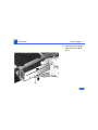
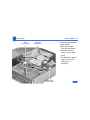
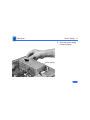
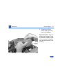
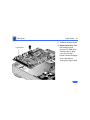
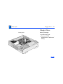
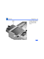
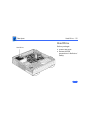
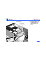
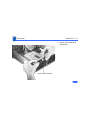
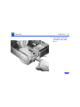
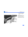
1
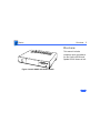
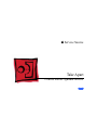
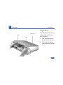
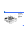
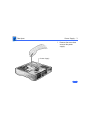
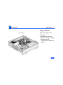
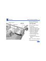
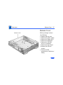
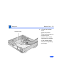
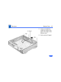
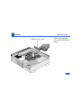
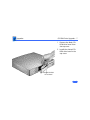
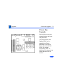
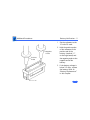
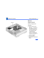
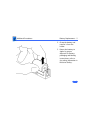
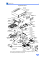
K Service Source
Centris 660AV/Quadra
660AV
K Service Source
Basics
Centris 660AV/Quadra 660AV
Basics
Overview - 2
Overview
This manual includes
complete repair procedures
for the Centris 660AV and
Quadra 660AV shown at left.
Figure: Centris 660AV and Quadra 660AV
K Service Source
Specifications
Centris 660AV/Quadra 660AV
Specifications
Processors - 1
Processors
Processor
Motorola 68040
25 MHz
Built-in paged memory management unit (PMMU), floating point
unit (FPU), and 8K memory cache
Addressing
32-bit registers
32-bit address/data bus
Direct Memory
Access (DMA)
A Peripheral Subsystem Controller (PSC) provides direct
memory access (DMA) between the 68040 buses and
peripheral devices
Specifications
Digital Signal
Processor (DSP)
Processors - 2
AT&T DSP3210 32-bit floating-point digital signal processor
Supports real-time tasks such as speech recognition, audio
compression, and analog modem signal processing.
Specifications
Memory - 3
Memory
RAM
8 MB (4 MB soldered DRAM plus 4 MB SIMM) standard,
expandable to 68 MB
72-pin SIMMs
70 ns access time
ROM
1 MB soldered on logic board
PRAM
256 bytes of parameter memory
Specifications
VRAM
Clock/Calendar
Calendar
Memory - 4
1 MB (two banks of 512K VRAM soldered on board)
Maximum pixel depths for graphics:
• 12-inch RGB (512 x 384) 24 bits per pixel
• 13/14-inch RGB (640 x 480) 16 bits per pixel
• 12-inch monochrome (640 x 480) 8 bits per pixel
• 15-inch portrait (640 x 870) - 8 bits per pixel
• 16-inch RGB (832 x 624) - 16 bits per pixel
• 19-inch RGB (1024 x 768) - 8 bits per pixel
• 21-inch monochrome (1152 x 870) - 8 bits per pixel
• 21-inch RGB (1152 x 870) - 8 bits per pixel
• VGA (640 x 480) - 16 bits per pixel
• SVGA (800 x 600) - 16 bits per pixel
CMOS custom chip with long-life lithium battery
Specifications
Disk Storage - 5
Disk Storage
Floppy Drive
1.4 MB Apple SuperDrive
Hard Drive
3.5 in., internal 80 or 500 MB hard drive
CD-ROM
Optional internal 5.25 in. CD-ROM drive
Specifications
I/O Interfaces - 6
I/O Interfaces
Expansion Slot
SCSI
Internal expansion slot supports either NuBus, processor-direct
slot (PDS) card, or digital audio/video expansion (DAVE) card
(with appropriate adapter)
One SCSI port; DB-25 connector
Supports a maximum of six external devices (internal SCSI
devices include the computer, which is always device 7)
Apple Desktop Bus
Two Apple Desktop Bus (ADB) ports for keyboard, mouse, and
low-speed input devices; mini DIN-4 connectors
Expansion Slot
Internal expansion slot supports either a processor-direct slot
card or 7-inch NuBus card (with appropriate adapter)
Specifications
Serial
High-Performance
Serial Port (Modem
Port)
Ethernet
I/O Interfaces - 7
Two RS-232/RS-422 serial ports
One mini DIN-8 port
One mini DIN-9 high performance modem port
230.4 Kbps maximum
Supports connection to analog, PBX, ISDN, facsimile (FAX), and
data telephone lines
Provides full-duplex telephone I/O at up to 14.4 Kbps
AppleTalk and V.22, V22.bis, V.29, and V.32 modem protocols
supported
Supports Apple HiPPort protocols
0.92 Mbps maximum, clocked externally
One Ethernet port; AUI-15 connector
Specifications
Audio
Video
I/O Interfaces - 8
One 16-bit stereo output port; one 16-bit stereo input port;
stereo mini phone jack connectors
Sample rates up to 48 kHz (44.1 kHz standard rate)
Uses the digital signal processor (DSP) chip
Supports stereo audio from internal CD drive
Video monitor port; DB-15 connector
Supports Apple monitors (up to 16 bits), NTSC, and PAL monitors
Supports VGA and SVGA monitors (with adapter cables)
Composite Video
Input port; RCA phono connector
Output port; RCA phono connector
S-video
Input port; DIN-7 connector
Output port; DIN-4 connector
Specifications
I/O Devices - 9
I/O Devices
Keyboard
Mouse
Microphone
Standard, extended, or adjustable keyboard connected through two
ADB ports
Maximum power draw for all ADB devices: 500 mA
Keyboard draws 25-80 mA
ADB Mouse II; mechanical tracking optical shaft or contact
encoding (low power)
Draws up to 80 mA
Optional electret, omnidirectional microphone
Microphone output voltage is 4 mV peak to peak at normal value
Mini phone plug connector
Specifications
Sound and Video - 10
Sound and Video
Sound Generator
Video
Enhanced Apple sound chip (EASC), including four-voice wave
table synthesis and stereo sampling generator capable of
driving stereo mini phone-jack headphones or stereo
equipment
Built-in VRAM video support for all Apple monitors (requires an
adapter for 21 in. monitors)
Supports many types of NTSC, PAL, VGA
Specifications
Electrical - 11
Electrical
A/C Line Voltage
100-240 VAC
Frequency
50-60 Hz
86 W
Power
CMOS custom chip with long-life lithium battery
Specifications
Physical - 12
Physical
Dimensions
Weight
Height: 3.4 in. (8.5 cm)
Width: 16.3 in. (41.5cm)
Depth: 15.6 in (39.7 cm)
14.0 lbs (6.4 kg) (weight varies based on internal devices
installed)
Specifications
Environmental - 13
Environmental
Operating
Temperature
Storage
Temperature
10-40° C (50-104 ° F)
-40 to 47° C (-40 F to 116.6° F)
Relative Humidity
Operating: 10-90% (noncondensing)
Altitude
0-10,000 ft. (3,048 m)
K Service Source
Troubleshooting
Centris 660AV/Quadra 660AV
Troubleshooting
General/ - 1
General
The Symptom Charts included in this chapter will help you
diagnose specific symptoms related to your product. Because cures
are listed on the charts in the order of most likely solution, try
the first cure first. Verify whether or not the product continues to
exhibit the symptom. If the symptom persists, try the next cure.
(Note: If you have replaced a module, reinstall the original module
before you proceed to the next cure.)
If you are not sure what the problem is, or if the Symptom Charts
do not resolve the problem, refer to the Flowchart for the product
family.
For additional assistance, contact Apple Technical Support.
Troubleshooting
Symptom Charts/Error Chords - 2
Symptom Charts
Error Chords
One-part error
chord sounds during
startup sequence
1
2
3
Two-part error chord
sounds during
startup sequence
1
2
3
Disconnect SCSI data cable and hard drive power cable.
Reboot system. If startup sequence is normal, run Macintosh
Hard Disk Test and replace hard drive, if necessary.
Disconnect floppy drive cable connector and reboot system. If
startup sequence is normal, replace floppy drive.
Replace logic board. Retain customer’s SIMMs.
Replace DRAM SIMMs.
Replace logic board. Retain customer’s SIMMs.
Perform DRAM SIMM verification on replacement logic
board.
Troubleshooting
Symptom Charts/System - 3
System
Does not power on,
screen is black, fan is
not running, and LED
is not lit
1
2
3
4
5
6
Check cables.
Plug monitor directly into wall socket and verify that
monitor has power.
Remove third-party RAM and cards.
Replace power cord.
Replace power supply.
Replace logic board. Retain customer’s SIMMs.
Clicking, Chirping, or
thumping
1
2
Replace power supply.
Replace logic board. Retain customer’s SIMMs.
Troubleshooting
Symptom Charts/System (Continued) - 4
System (Continued)
System shuts down
intermittently
System
intermittently
crashes or locks up
1
2
3
4
5
6
Make sure air vents are clear. Thermal protection circuitry
may shut down system. After 30 to 40 minutes, system
should be OK.
Replace power cord.
Check battery. Refer to “Battery
Verification” in Additional Procedures.
Replace power supply.
Replace logic board. Retain customer’s SIMMs.
1
2
3
4
5
6
Verify that system software is correct version.
Disconnect external SCSI devices.
Verify that application software is known-good.
Replace SIMMs.
Replace logic board. Retain customer’s SIMMs.
Replace power supply.
Troubleshooting
Symptom Charts/Floppy Drive - 5
Floppy Drive
Audio and video
present, but internal
floppy drive does not
operate
1
2
3
4
5
6
7
Replace disk with known-good.
Verify that all external SCSI devices
are disconnected.
Replace floppy drive cable.
Replace floppy drive.
Replace logic board. Retain customer’s SIMMs.
Replace power supply.
Disk ejects, display
shows icon with
blinking “X”
1
2
3
4
Replace disk with known-good system disk.
Replace internal floppy drive cable.
Replace internal floppy drive.
Replace logic board. Retain customer’s SIMMs
Troubleshooting
Symptom Charts/Floppy Drive (Continued) - 6
Floppy Drive (Continued)
Does not eject disk
1
2
3
4
Attempt to eject disk,
but doesn’t
1
2
3
4
Switch off computer. Hold mouse button down while you
switch computer on.
Replace floppy drive cable
Replace internal floppy drive.
Replace logic board. Retain customer’s SIMMs
Push disk completely in.
Reseat floppy drive bezel and drive so bezel slot aligns
correctly with drive.
Eject disk manually.
Replace floppy drive.
Troubleshooting
Symptom Charts/Floppy Drive (Continued) - 7
Floppy Drive (Continued)
MS-DOS drive does
not recognize disk
formatted on 1.4 MB
drive
1
2
To read and write files with either MS-DOS or 1.4 MB drive,
format all disks with MS-DOS drive first.
Verify the software is loaded.
Internal floppy drive
runs continuously
1
2
3
4
5
Replace disk with known-good system disk.
Remove external SCSI devices.
Replace internal floppy drive cable.
Replace internal floppy drive.
Replace logic board. Retain customer’s SIMMs.
Troubleshooting
Symptom Charts/Video - 8
Video
Screen is black, audio
and at least one drive
operate, fan is
running, and LED is
lit
1
Adjust brightness. See Adjustments chapter in appropriate
monitor manual.
2 Check cables.
3 Verify that monitor is switched on.
4 Clear parameter RAM. Hold down <Command> <Option> <P>
<R> during startup but before “Welcome To Macintosh”
appears.
5 Replace video cable.
6 Replace monitor. Refer to appropriate monitor manual to
troubleshoot defective monitor.
7 Replace video card, if present
8 Replace SIMMs.
9 Replace logic board. Retain customer’s SIMMs.
10 Replace power supply.
Troubleshooting
Symptom Charts/Video (Continued) - 9
Video (Continued)
Screen is black, audio
and drive do not
operate, but fan is
running and LED is lit
1
2
3
4
5
6
Remove peripherals and cards.
Remove expansion card.
Replace DRAM SIMMs. See Memory
manual.
Replace power supply.
Replace logic board.
Partial or whole
screen is bright and
audio is present, but
no video information
is visible
1
Replace monitor. Refer to appropriate monitor manual to
troubleshoot defective monitor.
Replace video cable.
Replace video card, if installed.
Clear parameter RAM. Hold down <Command> <Option> <P>
<R> during startup but before “Welcome To Macintosh”
appears.
Replace logic board. Retain customer’s SIMMs.
2
3
4
5
Troubleshooting
Symptom Charts/Hard Drive - 10
Hard Drive
Internal hard drive
will not operate;
drive doesn’t spin
1
2
3
4
Replace SCSI data cable.
Replace hard drive.
Replace power supply.
Replace logic board. Retain customer’s SIMMs.
Drive does not appear
on the desktop
1
2
Verify that there are no duplicate SCSI device addresses.
Clear parameter RAM. Hold down <Command> <Option> <P>
<R> during startup but before “Welcome To Macintosh”
appears.
Verify that drive is initialized. If it isn’t, use “HD SC Setup”
to initialize drive.
Replace SCSI data cable.
Replace hard drive.
3
4
5
Troubleshooting
Symptom Charts/Hard Drive (Continued) - 11
Hard Drive (Continued)
Works with internal
or external SCSI
devices but not with
both
1
2
3
4
Verify that there are no duplicate SCSI device addresses.
Replace terminator on external device.
Replace external SCSI data cables.
Refer to appropriate manual to troubleshoot defective
external device.
Troubleshooting
Symptom Charts/CD-ROM drive - 12
CD-ROM drive
CD-ROM drive does
not accept a compact
disc
1
2
3
Exchange disc (if disc is dirty or damaged).
Verify that CD-ROM carrier is installed properly.
Replace CD-ROM drive mechanism.
Macintosh does not
display CD-ROM
drive icon
1
2
3
4
Verify that CD-ROM extension is in System Folder.
Replace SCSI data cable.
Replace CD-ROM drive mechanism.
Replace logic board.
Compact disc won’t
eject from the drive
1
2
Manually eject the compact disc.
Press the eject button behind the front bezel (if it is
accessible).
Replace the CD-ROM drive mechanism.
3
Troubleshooting
Symptom Charts/Peripheral - 13
Peripheral
Cursor does not move
1
2
5
Check mouse connection.
Inspect inside of mouse for buildup of dirt or other
contaminants. Clean mouse if necessary.
If mouse was connected to keyboard, connect it to computer
ADB port instead. If mouse works, replace keyboard or ADB
cable.
If mouse does not work in any ADB port on computer, replace
mouse.
Replace logic board. Retain customer’s SIMMs.
1
2
Replace mouse.
Replace logic board. Retain customer’s SIMMs.
3
4
Cursor moves, but
clicking mouse
button has no effect
Troubleshooting
Symptom Charts/Peripheral (Continued) - 14
Peripheral (Continued)
Cannot double-click
to open application,
disk, or server
1
2
3
6
Remove duplicate System files from
hard drive.
Clear parameter RAM. Hold down <Command> <Option> <P>
<R> during startup but before “Welcome to Macintosh”
appears.
If mouse was connected to keyboard, connect mouse to
computer ADB port instead. If mouse works, replace
keyboard or ADB cable.
If mouse does not work in any ADB port on computer, replace
mouse.
Replace logic board. Retain customer’s SIMMs.
1
2
3
4
Check keyboard connection to ADB port.
Replace keyboard cable.
Replace keyboard.
Replace logic board. Retain customer’s SIMMs.
4
5
No response to any
key on keyboard
Troubleshooting
Symptom Charts/Peripheral (Continued) - 15
Peripheral (Continued)
Known-good serial
printer will not print
1
2
3
4
Verify that system software is correct version.
Make sure Chooser and Control Panel settings are correct.
Replace printer interface cable.
Replace logic board. Retain customer’s SIMMs.
Known-good printer
on a network will not
print
1
2
3
4
Verify that system software is correct version.
Make sure Chooser and Control Panel settings are correct.
Refer to Networks manual.
Replace logic board. Retain customer’s SIMMs.
Troubleshooting
Symptom Charts/Miscellaneous - 16
Miscellaneous
No sound from
speaker
1
2
3
4
Verify that volume setting in Control Panel is 1 or above.
Check speaker cable.
Replace speaker.
Replace logic board. Retain customer’s SIMMs.
Sound from external
video source does not
record or play
through speakers
1
Verify that audio cable connects sound source to sound input
port when using S-video.
Check speaker cable.
Replace speaker.
Replace logic board. Retain customer’s SIMMs.
2
3
4
K Service Source
Take Apart
Centris 660AV/Quadra 660AV
Take Apart
Top Cover - 1
Top Cover
Top Cover
Tab
Tab
No preliminary steps are
required before you begin
this procedure.
1
2
Press up on the tabs at
the back of the top cover.
Tilt the back of the top
cover and remove the top
cover.
Take Apart
Power Supply - 2
Power Supply
Power Supply
Before you begin, do the
following:
• remove the top cover.
• Review the ESD
precautions in Bulletins/
Safety.
Take Apart
Power Supply - 3
1
Power Supply
Remove the screw that
secures the power
supply.
Take Apart
Power Supply
Power Supply - 4
2
Tab
Floppy
Drive
For easier access to the
power supply, release
the floppy drive
mounting tabs. Slide the
floppy drive forward a
few inches.
Take Apart
Power Supply - 5
3
CD-ROM Audio Cable
4
SCSI Data Cable
CD-ROM
Drive Power
Cable
If a CD-ROM drive is
present, disconnect the
SCSI data cable and CDROM drive power cable
from the CD-ROM drive.
Disconnect the CD-ROM
audio cable.
Take Apart
Power Supply - 6
5
CD-ROM EMI Shield
Remove the CD-ROM
drive EMI shield.
Take Apart
Power Supply - 7
6
Tab
Press up on the tab and
slide out the CD-ROM
drive.
Take Apart
Main
Power Cable
Power Supply - 8
7
CD-ROM
Drive Power
Hard Drive
Power Cable
Disconnect these power
supply cables:
• Main power cable
from the logic board
• Hard drive power
cable from the hard
drive
• CD-ROM drive power
cable from the CDROM drive (if
installed)
Take Apart
Power Supply - 9
8
Power Supply
Slide the power supply
forward slightly.
Take Apart
Power Supply - 10
9
Power
Switch
Tilt the front of the
power supply and lift it
out of the computer.
Replacement Note: Move the
floppy drive forward. Press
the actuator toward the back
of the computer to properly
seat the power switch in the
actuator.
Take Apart
Logic Board - 11
Logic Board
Logic Board
Before you begin, do the
following:
• Remove the top cover
• Remove the Power supply
• Review the ESD
precautions in Bulletins/
Safety.
Take Apart
Logic Board - 12
Note: The logic board is
secured with two screws.
Standoff with Internal Screw
1
2
3
Phillips
Screw
Using a long Phillips
screwdriver, remove
the screw from the
center of the standoff.
Remove the standoff.
Remove the Phillips
screw from the front
edge of the logic board.
Take Apart
Logic Board - 13
LED Cable
4
5
Floppy
Drive
Cable
Speaker
Cable
Disconnect these cables
from the front edge of
the logic board:
• Floppy drive cable
• Speaker cable
• LED cable
• CD-ROM audio cable
(if present)
Note: Lift the front edge
of the logic board to
make removing the
floppy drive cable
easier.
Take Apart
Logic Board - 14
SCSI Data Cable
Video-out cable
Video-in cable
6
Disconnect these cables
from the back edge of the
logic board:
• Video-out cable
• Video-in cable
• SCSI data cable
Take Apart
Logic Board - 15
7
CD-ROM Drive
EMI Shield
Hard Drive EMI Shield
Remove the EMI shield
from the hard drive bay
and from the CD-ROM
bay, if the CD-ROM
drive is installed.
Take Apart
Logic Board - 16
8
9
Tab
Release the tab to unlock
the hard drive or CDROM, if installed.
Slide forward the hard
drive and CD-ROM
drive, if installed.
Take Apart
Logic Board - 17
Logic Board
10 Slide the logic board
about 1/2 inch toward
the front of the
computer.
Take Apart
Logic Board - 18
11 Remove the logic board.
Logic Board
12 Replacement Note: Slide
the hard drive and
optional CD-ROM drive
forward a bit to allow
room for the logic
board. Connect the floppy
drive cable before
securing the logic board.
Take Apart
Floppy Drive - 19
Floppy Drive
Floppy Drive
Before you begin:
• remove top cover.
• Review the ESD
precautions in Bulletins/
Safety.
Take Apart
Floppy Drive - 20
1
Floppy
Drive
Tab
Tab
Press the tabs outwards
and slide the floppy
drive forward a few
inches.
Take Apart
Floppy Drive - 21
2
Floppy
Drive
Cable
3
Disconnect the floppy
drive cable.
Note: You can easily
reach the floppy drive
cable connector when the
floppy drive is forward.
Slide out the floppy
drive.
Take Apart
Hard Drive - 22
Hard Drive
Hard Drive
Before you begin:
• remove top cover.
• Review the ESD
precautions in Bulletins/
Safety.
Take Apart
Hard Drive - 23
SCSI Data Cable
Hard Drive
Power Cable
1
Disconnect the SCSI data
and hard drive power
cables from the hard
drive.
Take Apart
Hard Drive - 24
2
Hard Drive EMI Shield
Remove the hard drive
EMI shield.
Take Apart
Hard Drive - 25
3
Tab
Press down on the tab
and slide out the hard
drive.
Take Apart
CD-ROM Drive - 26
CD-ROM Drive
CD-ROM Drive
Before you begin:
• remove the top cover.
• Review the ESD
precautions in Bulletins/
Safety.
Take Apart
CD-ROM Drive - 27
1
CD-ROM Audio Cable
2
CD-ROM
Power
Cable
SCSI Data Cable
Disconnect the SCSI data
cable and CD-ROM drive
power cable from the
CD-ROM drive.
Disconnect the CD-ROM
audio cable.
Take Apart
CD-ROM Drive - 28
3
CD-ROM EMI Shield
Remove the CD-ROM
drive EMI shield.
Take Apart
CD-ROM Drive - 29
4
Press up on the tab and
slide out the CD-ROM
drive.
Replacement Note: Be sure
to remove the CD-ROM drive
from the carrier prior to
returning the drive to Apple.
Tab
Take Apart
Internal Chassis and Speaker - 30
Internal Chassis Internal Chassis
Support Post
Rail and
Metal Tab
Tab
Internal Chassis
and Speaker
Before you begin: remove
the following:
• Remove the top cover
• Remove the power supply
• Remove the floppy drive
• Remove the hard drive
• Remove the CD-ROM
drive (if installed)
• Remove the logic board
• Review the ESD
precautions in Bulletins/
Safety.
Note: The chassis is secured
to the bottom cover by two
Take Apart
Internal Chassis and Speaker - 31
Internal Chassis
tabs at the front of the unit,
two rail and tab sets at the
sides of the unit, support
posts at the back of the
chassis, and hidden brackets
that slide into the bottom
cover.
1
2
3
Press up on one of the
front tabs while lifting
the support post.
Repeat this step on the
other side until the
internal chassis slides
easily toward the back
of the computer.
Press down and slide the
chassis toward the back
Take Apart
Internal Chassis and Speaker - 32
4
of the computer.
Remove the chassis.
Note: The LED cable,
floppy drive cable,
speaker and speaker
cable are not shipped
with the replacement
internal chassis.
Take Apart
Internal Chassis and Speaker - 33
Speaker Cable
LED Cable
Floppy Drive Cable
5
Turn the chassis over.
7
Remove the speaker
cable from its routing
guides.
6
Remove the floppy drive
cable and the LED cable.
Take Apart
Torx Screw
Internal Chassis and Speaker - 34
Speaker
8
9
Remove the two torx
screws from the
speaker.
Lift out the speaker.
Take Apart
Bottom Cover
Internal Chassis
Metal Tab
Rail
Internal Chassis and Speaker - 35
Replacement Note: Place
the internal chassis on the
floor of the bottom cover
with the front of the chassis
about 3/4 inch from the
front of the cover. Align the
side rails with the metal
tabs and slide the rails
under the metal tabs.
Take Apart
Internal Chassis and Speaker - 36
Replacement Note: After
carefully aligning the side
rails, push down firmly on
the chassis and slide it
toward the front of the unit.
The tabs will snap into
place.
Take Apart
Bottom Cover - 37
Bottom Cover
Bottom Cover
Before you begin: remove
the following:
• Remove the top cover
• Remove the power supply
• Remove the floppy drive
• Remove the hard drive
• Remove the CD-ROM
drive (if installed)
• Remove the logic board
• Remove the internal
chassis
• Review the ESD
precautions in Bulletins/
Safety
Take Apart
Bottom Cover - 38
1
2
Actuator
3
Tab
Tab
Shift the actuator toward
the back of the unit.
Squeeze together the tabs
on the shaft of the
actuator.
Remove the actuator.
Take Apart
Bottom Cover - 39
4
Insulator Sheet
Lift out the insulator
sheet.
Replacement Note:
There is only one correct
position for the
insulator sheet. Match
the notches on the sides
of the insulator sheet
with the corresponding
metal stops.
Take Apart
Bottom Cover - 40
5
I/O Panel
Tabs
Tabs
6
Using a screwdriver,
release the tabs on the
upper-rear edge of the
bottom cover.
Push out the I/O panel.
K Service Source
Upgrades
Centris 660AV/Quadra 660AV
Upgrades
Expansion Cards - 1
Expansion Cards
Expansion Card Slot
Before you begin, do the
following:
• Remove the top cover.
• Review the ESD
precautions in Bulletins/
Safety.
Upgrades
Expansion Cards - 2
Expansion Port Cover
1
Remove the expansion
port cover from the back
panel.
Upgrades
Expansion Cards - 3
Expansion Card
2
3
Adapter Card
Loosely connect the
expansion card
connector to the adapter
card connector.
Note: Be sure to fit the
adapter card pin into the
expansion card hole.
Gently press the
connectors together.
Upgrades
Expansion Cards - 4
4
Adapter
Card Tab
Adapter
Card
Connector
Bottom Case
Slot
Expansion Slot
Insert the connector on
the bottom of the
adapter card into the
expansion slot.
Note: Make sure that the
tab on the side of the
adapter card slides into
the slot on the side of the
bottom case.
Upgrades
Expansion Cards - 5
5
Thumbscrews
Attach the thumbscrews.
Upgrades
CD-ROM Drive Upgrade - 6
CD-ROM Drive Bay
CD-ROM Drive
Upgrade
Before you begin, do the
following:
• Remove the top cover.
• Review the ESD
precautions in Bulletins/
Safety.
Upgrades
CD-ROM Drive Upgrade - 7
1
2
Slotted CD-ROM
Drive Bezel
Remove the blank CDROM drive bezel from
the top cover.
Install the slotted CDROM drive bezel in the
top cover.
Upgrades
CD-ROM Drive Upgrade - 8
3
5.25'' Drive Bay Shield
Pry off the metal 5.25”
drive bay shield.
Upgrades
CD-ROM Drive Upgrade - 9
CD-ROM Drive Carrier
CD-ROM Drive
4
Attach the CD-ROM drive
carrier to the CD-ROM
drive with four Phillips
screws.
Upgrades
CD-ROM Drive Upgrade - 10
CD-ROM Drive
CD-ROM Drive Carrier
5
Push in the CD-ROM
drive and carrier.
Upgrades
CD-ROM Drive Upgrade - 11
6
Bottom Cover
7
Tabs
Slots
Align the slots at the
lower edge of the CDROM shield with the
tabs on the bottom cover.
Swing up the CD-ROM
shield until it snaps
securely onto the bottom
cover.
Upgrades
CD-ROM
Audio Cable
SCSI Data
Cable
CD-ROM Drive Upgrade - 12
CD-ROM Drive Power
Cable
8
9
CD-ROM
Cable Audio
Connect these cables
from the power supply
to the CD-ROM drive:
• CD-ROM audio cable
• SCSI data cable
• CD-ROM drive power
cable
Connect the other end of
the CD-ROM audio cable
to the logic board.
Upgrades
Power Mac Upgrade - 13
Power Mac
Upgrade
No preliminary steps are
required before you begin
this procedure.
The Centris 660AV and
Quadra 660AV can be
upgraded to a Power
Macintosh 6100/60 or
Power Macintosh 6100/
60AV. For upgrade
instructions, refer to
Additional Procedures in the
Power Macintosh 6100
manual.
K Service Source
Additional Procedures
Centris 660 AV/Quadra 660AV
Additional Procedures
Battery
Battery Verification - 1
Battery
Verification
Before you begin do the
following:
• Remove the top cover.
Warning: If handled or
discarded improperly,
the lithium battery in
the computer could
explode. Review
battery-handling and
disposal instructions in
Bulletins/Safety.
• Review the ESD
precautions in Bulletins/
Safety.
Additional Procedures
Battery Verification - 2
1
2
Negative
Probe
Positive
Probe
3
Set the voltmeter to the
10 volts DC scale.
Hold the positive probe
of the voltmeter to the
positive end of the
battery (marked “+”
on the logic board) and
the negative probe to the
negative end of the
battery.
If the battery voltage is
below 3.2 volts, replace
the battery. Refer to
“Battery Replacement”
in this chapter.
Additional Procedures
Battery
Battery Replacement - 3
Battery
Replacement
Before you begin do the
following:
• Remove the top cover.
Warning: If handled or
discarded improperly,
the lithium battery in
the computer could
explode. Review
battery-handling and
disposal instructions in
Bulletins/Safety.
• Review the ESD
precautions in Bulletins/
Safety.
Additional Procedures
Battery Replacement - 4
1
Using a small flat-blade
screwdriver, pry open
the latch at the end of the
battery holder and lift
off the cover.
Additional Procedures
Battery Replacement - 5
2
3
Grasp the battery and
remove it from the
holder.
Return the battery to
Apple for proper
disposal. For battery
packaging and labeling
instructions, refer to
the safety information in
Bulletins/Safety.
K Service Source
Exploded View
Centris 660AV/Quadra 660AV
Exploded View
1
Exploded View
Top Cover
922-0545
Blank Bezel
922-0358
Slotted CD Bezel
with Caddy
922-0355
Slotted CD Bezel
Caddiless
SCSI Cable
Power Supply
661-1688
Support
Column
922-0356
Internal Chassis
922-0359
Logic Board
661-1704
Floppy
Drive
Cable
922-0351
Speaker
922-0353
LED Cable
922-0354
Insulator Sheet
922-0866
On/Off Actuator
922-0357
AV Adapter Cables
CD Audio Cable
922-0842
Manual Insert
Floppy Drive
Floppy Drive
Carrier
805-0961
Expansion
Port Cover
922-0902
Rear
Housing
922-0864
Feet (4)
922-0862
Bottom Cover
922-0806
Floppy
Shield
922-0826
* CD-ROM
Drive
Hard Drive*
Hard Drive Carrier
922-1806
PDS Adapter
NuBus Adapter
661-1719
CD-ROM Hard Drive
Shield
Carrier
922-0850 922-0367
CD-ROM
Shield
922-0826
This is a generic representation of a product family. Configurations may vary.
For number of part with asterisk, see parts list.
Blank
Shield