1
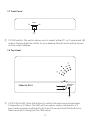
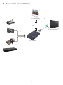
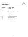
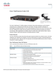
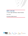
CM-398DI CV/SV to DVI-I Converter Operation Manual CM-398DI Disclaimers The information in this manual has been carefully checked and is believed to be accurate. Cypress Technology assumes no responsibility for any infringements of patents or other rights of third parties which may result from its use. Cypress Technology assumes no responsibility for any inaccuracies that may be contained in this document. Cypress also makes no commitment to update or to keep current the information contained in this document. Cypress Technology reserves the right to make improvements to this document and/or product at any time and without notice. Copyright Notice No part of this document may be reproduced, transmitted, transcribed, stored in a retrieval system, or any of its part translated into any language or computer file, in any form or by any means - electronic, mechanical, magnetic, optical, chemical, manual, or otherwise - without express written permission and consent from Cypress Technology. © Copyright 2011 by Cypress Technology. All Rights Reserved. Version 1.0 March 2011 Trademark Acknowledgments All products or service names mentioned in this document may be trademarks of the companies with which they are associated. Safety Precautions Please read all instructions before attempting to unpack or install or operate this equipment, and before connecting the power supply. Please keep the following in mind as you unpack and install this equipment: Always follow basic safety precautions to reduce the risk of fire, electrical shock and injury to persons. To prevent fire or shock hazard, do not expose the unit to rain, moisture or install this product near water. Never spill liquid of any kind on or into this product. Never push an object of any kind into this product through module openings or empty slots, as you may damage parts. Do not attach the power supply cabling to building surfaces. Do not allow anything to rest on the power cabling or allow it to be abused by persons walking on it. To protect the equipment from overheating, do not block the slots and openings in the module housing that provide ventilation. Revision History Version No VS0.1 Date 20110428 Summary of Change Preliminary Release Table of Contents 1. Introduction ……………………..……………………...…........….……. 1 2. Applications …………………..………………….……...................….. 1 3. Package Contents ………………………...........……….................… 1 4. System Requirements ……………..……….........………............……. 1 5. Features …………………………………………......……........…...…… 2 6. Specifications ………………………………...……..........………....…. 3 7. Operation Controls and Functions ……………...……..............…… 7.1 Left side Panel ......................................................................... 4 7.2 Right side Panel .……………..……………..…….......…...….… 4 7.3 Front Panel .…………………………......…..…….......…...…......… 5 7.4 Top Panel .…….....……………………………...…….......…...….… 5 8. OSD ......................................…......……………..............…..…....…... 6 9. Connection and Installation ….………………….........…..…..…...... 7 10. Acronyms …...................................................................................... 8 4 1. Introduction The CV/SV to DVI-I Converter is a compact device that allows you to show content from Composite Video (CV) or S-Video (SV) sources on PC monitors or Component televisions. Compact and lightweight this easy to use device allows you to convert CV/SV (NTSC or PAL) formatted content to DVI-I (digital and analog) resolutions from XGA to UXGA or HD resolutions from 480p to 1080p and thanks to frame rate conversion you can view content from DVD/ Blu-Ray players or game consoles on DVI monitors. With advanced 3D motion adaptive de-interlace that helps to eliminate jagged edges when displaying content on TV’s, the CM-398DI CV/SV to DVI-I Converter is a useful tool for professionals that work with CV/SV sources and DVI displays. 2. Applications 2. Applications Display CV/SV signals on DVI monitors Show content from Set-Top-Boxes (STB) or Camcorders on DVI monitors 3. Package Contents CV/SV to DVI Converter Power Adaptor Operation Manual 4. System Requirements To operate this system effectively the following equipment is needed: A source device, for example a DVD player or STB, output DVI monitor and connection cables. 1 5. Features Supports NTSC 3.58 and PAL High Quality Scaling Engine Output resolution: ■ PC: XGA, SXGA, UXGA ■ DVI: 480p/576p, 720p, 1080p@50/60 3D (frame based) motion adaptive YNR/CNR noise reduction (for Y/C video input) An intuitive On Screen Display Advanced 3D motion adaptive de-interlace Automatic 2:2 & 3:2 film mode detection Plug & play- no driver software required 2 6. Specifications Input port Output port Output Resolution 1 x CV, 1 x SV 1 x DVI PC: XGA/SXGA/UXGA HD: 480p/576p/720p/1080p@50/ 60Hz Power Supply 5V DC/1A (US/EU standards, CE/FCC/UL certified) ESD Protection Human body model: ± 8kV (air-gap discharge) ± 4kV (contact discharge) Dimensions (mm) 162.6 (W) x 164.5 (D) x 33.5 (H) Weight(g) 100 Chassis Material Plastic Silkscreen Color Black Operating Temperature 0˚C ~ 40˚C / 32˚F ~ 104˚F Storage Temperature -20˚C ~ 60˚C / -4˚F ~ 140˚F Relative Humidity 20~90% RH (no condensation) Power Consumption (W) 2 (Max) 3 7. Operation Controls and Functions The following sections describe the hardware components of the unit. 7.1 Left side Panel Video S-Video In DC 5V ① ② ③ ① S-Video input: This port is where you connect the S-Video source, such as a digital camcorder/camera to the converter with an S-Video cable in order to receive an input signal. ② Composite Video input: Using a Composite Video cable connect the source device, for example a camcorder to the converter in order to receive an input signal. ③ DC 5V In: This jack is where you plug the 5V DC power supply into the unit and connect the adaptor to an AC outlet. 7.2 Right side Panel DVI-I Out ① ① DVI-I OUT: This port allows you to connect to a DVI monitor using a DVI cable. 4 7.3 Front Panel PC Mode HD ① ① PC/HD switch: This switch allows you to select either PC or Component HD output. Simply slide the switch to your desired format and it will be shown on the output display. 7.4 Top Panel CV:Yellow SV:Red Video to DVI-I ① ① CV/SV SW & LED: Press this button to switch the input source between Composite or S-Video. The LED will turn yellow when switched to CV input and red when switched to SV input. Press and hold this button for three seconds to bring up the OSD menu. 5 8. OSD ← INput Format / Output Resolution ← PC Monitor Infomation ← Firmware Information 1. Press the select input button once to switch between CV/SV input. If the source is disconnected the OSD will show “No Signal”. 2. Enter the OSD menu. 3. When the device is in PC mode the OSD will display the input format, output timing, user selectable output timings, the detected source as well as the PC monitor’s EDID and firmware version as shown in the above screen capture. 4. When in HD mode the OSD will display the input format, output timing, frame rate options, video system and the firmware version as shown in the below screen capture. 5. Press the Select Input button to cycle through the different timings until you reach your desired timing. IN CVBS OUT 480p60 ← Input Format / Output Resolution ← Firmware Information 6 9. Connection and installation PC Monitor or 3 RCA DVI DVI CM-398DI 7 Component TV A Acronyms Acronym Complete Term CV Composite Video HD High Definition NTSC National Television System Committee PAL Phase Alternate Line PC Personal computer STB Set-Top-Box SV S-Video SXGA Super eXtended Graphics Array VGA Video Graphics Array XGA Extended Graphics Array UXGA Ultra eXtended Graphic Array 8 CYPRESS TECHNOLOGY CO., LTD. Home page: http://www.cypress.com.tw 20101021 MPM-CM398DI