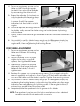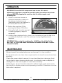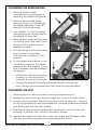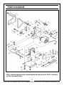
1
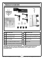
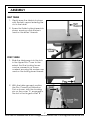
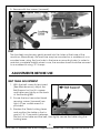
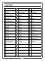
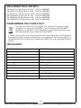
BELT/DISC SANDER
MODEL NO: CBS1-5
PART NO: 6500403
OPERATION & MAINTENANCE
INSTRUCTIONS
GC0414
INTRODUCTION
Thank you for purchasing this CLARKE Belt and Disc Sander, which is designed
for hobby, DIY and light workshop use for sanding wood and wood products.
Before attempting to use this product, please read this manual thoroughly and
follow the instructions carefully. In doing so you will ensure the safety of yourself
and that of others around you, and you can look forward to your purchase
giving you long and satisfactory service.
GUARANTEE
This product is guaranteed against faulty manufacture for a period of 12
months from the date of purchase. Please keep your receipt which will be
required as proof of purchase.
This guarantee is invalid if the product is found to have been abused or
tampered with in any way, or not used for the purpose for which it was
intended.
Faulty goods should be returned to their place of purchase, no product can
be returned to us without prior permission.
This guarantee does not effect your statutory rights.
GENERAL SAFETY RULES
WARNING: WHEN USING ELECTRIC TOOLS, BASIC SAFETY PRECAUTIONS
SHOULD ALWAYS BE FOLLOWED TO REDUCE THE RISK OF FIRE, ELECTRIC
SHOCK AND PERSONAL INJURY INCLUDING THE FOLLOWING. READ ALL
THESE INSTRUCTIONS BEFORE ATTEMPTING TO OPERATE THIS PRODUCT
AND SAVE THESE INSTRUCTIONS FOR FUTURE REFERENCE.
GENERAL SAFETY IN THE WORKPLACE
1. ALWAYS ensure that air can circulate around the machine and that the air
vents are unobstructed.
2. ALWAYS keep work area clean & tidy. Cluttered work areas and benches
invite accidents.
3. NEVER over-reach. Keep proper footing and balance at all times.
4. NEVER store equipment in a wet/damp environment or expose to rain.
2
Parts & Service: 020 8988 7400 / E-mail: [email protected] or [email protected]
5. KEEP other persons away. Do not let persons, especially children, not
involved in the work, touch the tool or extension cable and keep them
away from the work area.
6. NEVER operate a machine when under the influence of alcohol, drugs or
medication.
7. ALWAYS ensure the workplace is well lit. Ensure that lighting is placed so that
you will not be working in your own shadow.
8. Do not use tools in the presence of flammable liquids or gasses.
9. Stay alert, watch what you are doing, use common sense and do not
operate the tool when you are tired.
CARE OF POWER TOOLS
1. Read this manual carefully. Learn the machines applications and
limitations, as well as the specific potential hazards peculiar to it.
2. ALWAYS keep guards in place and in working order. A guard or other part
that is damaged should be properly repaired or replaced by an authorised
service centre, unless otherwise indicated in this instruction manual.
3. Don’t force the machine and use the correct tool. It will do the job better
and safer, at the rate for which it was intended.
4. ALWAYS disconnect the machine from the power supply before carrying
out any servicing or changing of accessories.
5. Before further use of the tool, it should be carefully checked to determine
that it will operate properly and perform its intended function. Check for
alignment of moving parts, binding of moving parts, breakage of parts,
mounting or other condition that may affect its operation.
6. Have defective switches repaired by an authorised service centre. Do not
use a tool if the switch does not turn it on and off.
7. ALWAYS check for any damage or any condition that could affect the
operation of the machine. Damaged parts should be properly repaired.
8. Have your tool repaired by a qualified person. This tool complies with the
relevant safety rules. Repairs should only be carried out by qualified
persons using original spare parts, otherwise this may result in considerable
danger to the user.
9. NEVER use this product for any other purpose than that described in this
booklet.
10. NEVER abuse the power cable by yanking the cable to disconnect it from
the socket. Keep the cable away from heat, oil or sharp edges.
11. Guard against electric shock. Avoid body contact with earthed or
grounded surfaces.
3
Parts & Service: 020 8988 7400 / E-mail: [email protected] or [email protected]
12. If the machine should be used outdoors, use only extension cables
intended for outdoor use and marked accordingly.
13. Avoid accidental starting by making sure the power switch is off before
plugging in the power cable.
ADDITIONAL PRECAUTIONS FOR BELT & DISC SANDERS
1. ALWAYS wear ear protectors/defenders when using this machine.
2. ALWAYS wear a dust mask when using this machine. Be aware of harmful or
toxic dust produced when sanding some woods, paint, etc.
3. ALWAYS use the sanding belt support or table to support the workpiece.
4. Always check to ensure that the table, belt support and attachments are
secure before starting.
5. ALWAYS maintain a clearance of 1.5-2mm between the table and the
sanding belt or disc.
6. ALWAYS hold the workpiece firmly so that it cannot be pulled from your
hands.
7. ALWAYS feed the workpiece against the direction of rotation of the disc. i.e
the LEFT side of the disc.
8. ALWAYS keep the mains cable well away from the machine and ensure an
adequate electrical supply is close at hand so that the operation is not
restricted by the length of the cable.
9. ALWAYS use a dust extraction device, properly connected to the dust
extraction port.
10. ALWAYS ensure that nails or any foreign objects have been removed from a
workpiece beforehand. Nails etc., will destroy the belt or disc.
11. NEVER allow the ventilation slots in the motor to become blocked.
12. NEVER sand pieces which cannot be held firmly by hand.
WARNING: USE ONLY FOR SANDING WOOD. DO NOT USE FOR MATERIALS
CONTAINING ASBESTOS, PAINTED SURFACES OR MATERIALS WHICH EMIT TOXIC
PARTICLES.
DUST EXTRACTION
The sander is provided with a dust extraction facility. Please note however,
that this does not preclude the user from wearing a face mask to prevent the
inhalation of dust particles.
It is an EEC requirement that a dust extraction facility be provided on power
tools, however, due to the nature of the sander, some of the dust produced
will be forced into the surrounding atmosphere and will not be collected.
4
Parts & Service: 020 8988 7400 / E-mail: [email protected] or [email protected]
ELECTRICAL CONNECTIONS
WARNING: READ THESE ELECTRICAL SAFETY INSTRUCTIONS
THOROUGHLY BEFORE CONNECTING THE PRODUCT TO THE MAINS
SUPPLY.
Before switching the product on, make sure that the voltage of your electricity
supply is the same as that indicated on the rating plate. This product is
designed to operate on 230VAC 50Hz. Connecting it to any other power
source may cause damage.
This product may be fitted with a non-rewireable plug. If it is necessary to
change the fuse in the plug, the fuse cover must be refitted. If the fuse cover
becomes lost or damaged, the plug must not be used until a suitable
replacement is obtained.
If the plug has to be changed because it is not suitable for your socket, or due to
damage, it should be cut off and a replacement fitted, following the wiring instructions
shown below. The old plug must be disposed of safely, as insertion into a mains socket
could cause an electrical hazard.
WARNING! The wires in the power cable of this product are
coloured in accordance with the following code:
Blue = Neutral
Brown = Live Yellow and Green = Earth
• The wire which is coloured Blue must be connected to the terminal
which is marked N or coloured Black.
• The wire which is coloured Brown must be connected to the terminal
which is marked L or coloured Red.
• The wire which is coloured Yellow and Green must be connected to
the terminal which is marked E ( ) or coloured Green.
Plug must be BS1363/A approved.
Always fit a 5 Amp fuse.
Earth
(Green and Yellow)
Live
Neutral
(Brown)
(Blue)
Ensure that the outer sheath of the cable is firmly held by the clamp
WE STRONGLY RECOMMEND THAT THIS MACHINE IS CONNECTED TO THE MAINS
SUPPLY VIA A RESIDUAL CURRENT DEVICE (RCD).
If in any doubt, consult a qualified electrician. DO NOT attempt any repairs
yourself.
5
Parts & Service: 020 8988 7400 / E-mail: [email protected] or [email protected]
PRODUCT OVERVIEW
1
2
3
4
NO DESCRIPTION
NO DESCRIPTION
A
Disc Sanding Table
F
Vertical Table Locking Levers
B
Belt Sanding Table
G
Flat Washers (for use with E & F)
C
Mitre Gauge
H
Rubber Feet
D
Disc Cover/Dust Extract Point
J
Allen Keys
E
Disc Sanding Table Locking Levers
WARNING: THE USE OF ANY ACCESSORY/ATTACHMENT OTHER THAN THOSE
RECOMMENDED IN THIS INSTRUCTION MANUAL MAY PRESENT A RISK OF
PERSONAL INJURY.
6
Parts & Service: 020 8988 7400 / E-mail: [email protected] or [email protected]
ASSEMBLY
BELT TABLE
1. Gently ease the table into place
with the belt support entering the
slot in the table.
2. Screw the Table Locking Lever into
place, ensuring a flat washer is
used on the levers’ threads.
DISC TABLE
1. Slide the table pegs into the slots
in the Upper Disc Cover to the
extent that the Locking Levers
can be screwed in as shown
overleaf, ensuring flat washers are
used on the locking lever threads.
2. With the table secured, position
the Disc Cover/Dust Extraction
Port as shown, with the locating
pin on the cover ‘A’, engaged in
the slot in the hinged cover ‘B’.
7
Parts & Service: 020 8988 7400 / E-mail: [email protected] or [email protected]
3. Secure with four screws (arrowed).
1
2
FEET
The four feet may be very gently eased into the holes at the base of the
machine. Alternatively, the machine may be mounted on a workbench or a
wooden base, using the four holes in the base as mounting holes. In order to
maintain complete stability when in use, the wooden base should be secured
to a workbench using ‘G’ clamps.
ADJUSTMENTS BEFORE USE
BELT TABLE ADJUSTMENT
1. With the belt correctly tensioned
(See Maintenance), adjust the
Belt Support so that it is square
and bears very lightly on the back
of the Sanding Belt.
2. Ensure the two hex socket head
securing screws (arrowed) are
tight. A hex. socket wrench is
provided.
3. Slacken the Table Locking Lever
and position the table so that a
gap of 1.5 - 2 mm exists between
the slot in the table and the belt, then lightly secure the table using the
locking lever.
8
Parts & Service: 020 8988 7400 / E-mail: [email protected] or [email protected]
4. Place an engineers square on the
table so that it butts up against
the belt, then unlock the adjuster
by unscrewing the locknut at B.
5. Screw the adjuster A, clockwise or
anticlockwise whilst bearing down
on the table at a point adjacent
to screw A, until the square
indicates that the table is at right
angles.
6. Lock the adjuster, ensuring the nut is tight, then, maintaining pressure on
the table, finally secure the table using the locking lever. by turning
anticlockwise.
7. Finally, check to ensure the gap between the table and belt is between 1.5
- 2 mm.
8. It is possible to set the table to any angle up to 45 degrees, simply by
slackening the locking lever and positioning the table using a protractor or
angle setter, then retightening the locking lever.
DISC TABLE ADJUSTMENT
1. Place an engineers square on the
table and slacken the locking
levers slightly.
2. Adjust the table so it is at right
angles to the disc, using the
square, then tighten the levers.
3. If necessary, adjust the pointer,
adjacent to the angle indicator
beneath the table, so that it
registers zero.
4. Slacken the upper disc cover securing screws (A on page 8) using the
wrench supplied, and adjust so that a gap of 2-3mm exists between the
disc and the table and the table is square. Tighten the securing screws.
5. It is possible to set the table to any angle up to 45 degrees, simply by
slackening the locking levers and positioning the table using the angle
indicator, then retightening the locking levers. If the angle is critical, a
protractor or angle setter should be used.
6. If required, slide the quadrant into its groove in the table.
NOTE: The quadrant may be used to hold a workpiece at any desired
angle for sanding that angle with accuracy.
9
Parts & Service: 020 8988 7400 / E-mail: [email protected] or [email protected]
OPERATION
IMPORTANT: Ensure that ALL components are secure, ALL correct
adjustments have been carried out, and ALL safety precautions have been
observed BEFORE plugging the machine into the mains supply, and
switching ON.
1. Attach a vacuum cleaner or
other dust extraction device to
the relevant extraction port
(depending upon the medium to
be used) and switch it ON.
2. Switch the machine ON by
pressing the Green ON button.
3. If using the belt, check to ensure it
is tracking properly...adjust if
necessary.
4. Holding the workpiece firmly, place it on the table and gently slide it into
contact with the belt or disc. Do not force it, only a light pressure is
required.
IMPORTANT: When using the sanding disc, ALWAYS use the left half of the
disc ONLY, i.e. that, side where the direction of rotation of the disc is down
towards the table.
MAINTENANCE
Always inspect the sander before use and ensure it is in top condition.
Ensure all air vents are clear. (Use compressed air to clean the machine where
possible).
Check the power cable to ensure it is sound and free from damage. Avoid
using solvents when cleaning plastic parts, (most plastics are susceptible to
damage from the various types of commercial solvents).
All bearings in this tool are lubricated with sufficient high grade lubricant for
the machine’s lifetime under normal operating conditions, therefore no further
lubrication is required.
10
Parts & Service: 020 8988 7400 / E-mail: [email protected] or [email protected]
CHANGING THE SANDING BELT
1. Remove the belt table
completely by unscrewing and
removing the table locking lever.
2. Remove the two side cover
securing screws (A), followed by
the upper roller pivot screw (B),
then pull off the side cover.
3. Turn Adjuster (C) anti-clockwise,
sufficiently for the sanding belt to
be slipped off the rollers.
4. Replace the sanding belt ensuring
it is central about the rollers, and
the arrow (D) is pointing down
towards he table.
5. Turn the belt by hand and observe
how it moves on the rollers,
indicated by its position on the
support.
6. This will determine whether or not
it is tracking correctly. If it moves
sideways, turn the adjuster (C), so
that it stabilises over the middle of
the support.
• At this point the belt is tracking
properly. It is tensioned automatically & cannot be adjuste
• Turning the adjuster clockwise will cause the belt to move one
way...turning it anticlockwise and it will have the opposite effect.
CHANGING THE DISC
1. Remove the disc table and lower cover/dust extraction port.
2. Slacken the two screws securing the upper disc cover and slide it back.
3. Using a sharp instrument, tease off a portion of the sanding disc, sufficient
for it to be grasped by hand and peeled off. Remove all residual adhesive
and finally clean the disc with solvent.
4. Peel the backing from the replacement sanding disc and fix to the disc
ensuring it is central. Press it firmly to ensure it is secure.
5. Replace the table and lower disc cover, and adjust gap between table
and disc by positioning and securing the upper disc cover.
11
Parts & Service: 020 8988 7400 / E-mail: [email protected] or [email protected]
PARTS DIAGRAM
When requesting spare parts, please quote the reference HT-CBS1-5 followed
by the id number listed.
12
Parts & Service: 020 8988 7400 / E-mail: [email protected] or [email protected]
PARTS LIST
ID
DESCRIPTION
ID
DESCRIPTION
31 Screw
ID
DESCRIPTION
1
Knob
61 Pointer
2
Cover
32 Elastic Washer
62 Sliding Bar
3
Label
33 Washer
63 Table
4
Warning Label
34 Wheel
64 Pin
5
Belt
35 Insert
65 Screw
6
Circlip
36 Bolt
66 Spring
7
Bearing
37 Screw
67 Lever
8
Driven Wheel
38 Table
68 Bolt
9
Shaft
39 Nut
69 Washer
10 Plastic Belt Guard
40 Washer
70 Lower Disc Cover
11 Washer
41 Bolt
71 Washer
12 Screw
42 Lever
72 Screw
13 Screw
43 Spring
73 Screw
14 Pulley
44 Screw
74 Rubber Pad
15 Body
45 Screw
75 Base
16 Adjustable Shaft
46 Motor
76 Washer
17 Spring
47 Screw
77 Spring Washer
18 Washer
48 Washer
78 Bolt
19 Circlip
49 Screw
79 Rubber Pad
20 Spring Pin
50 Washer
80 Side Cover
21 Adjustable Plate
51 Pointer
81 Washer
22 Spring
52 Cover
82 Spring Washer
23 Spring
53 Screw
83 Screw
24 Knob
54 Disc
25 Washer
55 Sanding Disc
26 Bolt
56 Knob
27 Screw
57 Washer
28 Washer
58 Mitre Gauge
29 Support Bracket
59 Screw
30 Nut
60 Washer
13
Parts & Service: 020 8988 7400 / E-mail: [email protected] or [email protected]
REPLACEMENT DISCS AND BELTS
Sanding Discs 60 grit (pack of 5). Part No: 6502345
Sanding Discs 80 grit (pack of 5). Part No: 6502350
Sanding Discs 120 grit (pack of 5). Part No: 6502355
Sanding Belts 60 grit (pack of 5). Part No: 6502330
Sanding Belts 80 grit (pack of 5). Part No: 6502335
Sanding Belts 120 grit (pack of 5). Part No: 6502340
ENVIRONMENTAL RECYCLING POLICY
Through purchase of this product, the customer is taking on the
obligation to deal with the WEEE in accordance with the WEEE
regulations in relation to the treatment, recycling & recovery and
environmentally sound disposal of the WEEE.
In effect, this means that this product must not be disposed of with general
household waste. It must be disposed of according to the laws governing
Waste Electrical and Electronic Equipment (WEEE) at a recognised disposal
facility.
SPECIFICATION
Electrical Supply
230V 50Hz 1 ph
Power rating
300 Watt motor
Fuse rating
5 Amp
Motor Speed
2800 rpm
Net Weight
8kg
Sanding Disc Size
127mm (5”)
Belt Width
25mm (1”)
Belt Speed
13.5m/s
Dust Extract Port Dia
47mm (1.7/8”)
Dimensions (L x W x H)
360 x 280 x 390mm
Insulation Class
B
14
Parts & Service: 020 8988 7400 / E-mail: [email protected] or [email protected]
DECLARATION OF CONFORMITY
15
Parts & Service: 020 8988 7400 / E-mail: [email protected] or [email protected]