1
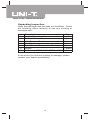
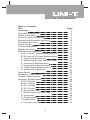
Model UT58E: OPERATING MANUAL
Table of Contents
Title
Overview
Unpacking Inspection
Safety Information
Rules For Safe Operation
International Electrical Symbols
The Meter Structure
Rotary Switch
Functional Buttons
Display Symbols
Measurement Operation
A. DC and AC Voltage Measurement
B. DC and AC Current Measurement
C. Measuring Resistance
D. Measuring Diodes and Continuity
E. Frequency Measurement
F. Temperature Measurement
G. Capacitance Measurement
H. Measuring Transistor
Sleep Mode
Operation of Hold Mode
General Specifications
Accuracy Specifications
A. DC Voltage
B. AC Voltage
C. DC Current
D. AC Current
E. Resistance Test
F. Diodes and Continuity Test
G. Frequency
H. Temperature
I. Capacitance
J. Transistor test
1
Page
3
4
5
6
8
9
10
11
12
14
14
15
17
18
20
21
23
25
26
26
27
28
28
28
28
29
29
30
30
31
31
31
Model UT58E: OPERATING MANUAL
Title
Maintenance
A. General Services
B. Replacing the Fuses
C. Replacing the Battery
Page
32
32
32
33
2
Model UT58E: OPERATING MANUAL
Overview
Warning
To avoid electric shock or personal injury, read the
“Safety Information” and “Rules for Safety Operation”
carefully before using the Meter.
Digital Multimeters Model UT58E (hereafter referred to
as “the Meter”) is 4 1/2 digits with ex-large LCD, steady
operations, fashionable structure and highly reliable
hand-held measuring instrument. The Meter uses large
scale of integrated circuit with double integrated A/D
converter as its core and has full range overload
protection. The Meter has 28 different measuring
functions. It has not only can measure AC/DC Voltage,
AC/DC Current, Resistance, Temperature, Capacitance,
Frequency, Transistor, Diode and Continuity, but also
have Data Hold, Full Icon Display, Overload Protection
and Sleep Mode features.
3
Model UT58E: OPERATING MANUAL
Unpacking Inspection
Open the package case and take out the Meter. Check
the following items carefully to see any missing or
damaged part:
Item
1
2
3
4
5
6
7
Qty
Description
English Operating Manual
1 piece
Test Lead
1 pair
Multi-Purpose Socket
1 piece
1 piece
Test Clip
1 piece
Point Contact Temperature Probe
Holster
1 piece
9V Battery (NEDA 1604, 6F22 or 009P)1 piece
In the event you find any missing or damage, please
contact your dealer immediately.
4
Model UT58E: OPERATING MANUAL
Safety Information
This Meter complies with the standards IEC61010: in
pollution degree 2, overvoltage category (CAT. II 1000V,
CAT. III 600V) and double insulation.
CAT. II: Local level, appliance, PORTABLE EQUIPMENT
etc., with smaller transient voltage overvoltages than
CAT. III
CAT. III: Distribution level, fixed installation, with smaller
transient overvoltages than CAT. IV
Use the Meter only as specified in this operating manual,
otherwise the protection provided by the Meter may be
impaired.
In this manual, a Warning identifies conditions and
actions that pose hazards to the user, or may damage
the Meter or the equipment under test.
A Note identifies the information that user should pay
attention to.
International electrical symbols used on the Meter and
in this Operating Manual are explained on page8
5
Model UT58E: OPERATING MANUAL
Rules For Safe Operation (1)
Warning
To avoid possible electric shock or personal injury,
and to avoid possible damage to the Meter or to the
equipment under test, adhere to the following rules:
l Before using the Meter inspect the case. Do not
use the Meter if it is damaged or the case (or part
of the case) is removed. Look for cracks or missing
plastic. Pay attention to the insulation around
the connectors.
l Inspect the test leads for damaged insulation or
exposed metal. Check the test leads for continuity.
Replace damaged test leads with identical model
number or electrical specifications before using
the Meter.
l Do not apply more than the rated voltage, as
marked on the Meter, between the terminals or
between any terminal and grounding.
l The rotary switch should be placed in the right
position and no any changeover of range shall
be made during measurement is conducted to
prevent damage of the Meter.
l When the Meter working at an effective voltage
over 60V in DC or 30V rms in AC, special care
should be taken for there is danger of electric
shock.
l Use the proper terminals, function, and range for
your measurements.
l If the value to be measured is unknown, use the
maximum measurement position and reduce the
range stop by step until a satisfactory reading is
obtained.
l Do not use or store the Meter in an environment
of high temperature, humidity, explosive, inflammable
and strong magnetic field. The performance of
the Meter may deteriorate after dampened.
6
Model UT58E: OPERATING MANUAL
Rules For Safe Operation (2)
l
l
l
l
l
l
l
l
l
l
l
When using the test leads, keep your fingers
behind the finger guards.
Disconnect circuit power and discharge all high
-voltage capacitors before testing resistance,
continuity, diodes, capacitance or current.
Before measuring current, check the Meter’s
fuses and turn off power to the circuit before
connecting the Meter to the circuit.
Replace the battery as soon as the battery indicator
appears. With a low battery, the Meter might
produce false readings that can lead to electric
shock and personal injury.
Remove test leads and multi-purpose socket from
the Meter and turn the Meter power off before
opening the Meter case.
When servicing the Meter, use only the same
model number or identical electrical specifications
replacement parts.
The internal circuit of the Meter shall not be altered
at will to avoid damage of the Meter and any accident.
Soft cloth and mild detergent should be used to
clean the surface of the Meter when servicing.
No abrasive and solvent should be used to prevent
the surface of the Meter from corrosion, damage
and accident.
The Meter is suitable for indoor use.
Turn the Meter power off when it is not in use
and take out the battery when not using for a long
time.
Constantly check the battery as it may leak when
it has been using for some time, replace the battery
as soon as leaking appears. A leaking battery will
damage the Meter.
7
Model UT58E: OPERATING MANUAL
International Electrical Symbols
AC (Alternating Current).
DC (Direct Current).
Grounding.
Double Insulated.
Deficiency of Built-In Battery.
Warning. Refer to the Operating Manual.
Diode.
Fuse.
Continuity Test.
Conforms to Standards of European Union.
8
Model UT58E: OPERATING MANUAL
The Meter Structure (see figure 1)
( figure 1)
1
2
3
4
5
6
7
8
LCD Display
HOLD Button.
Rotary Switch
COM Input Terminal
POWER
Other Input Terminal.
mA Input Terminal
20A Input Terminal
9
Model UT58E: OPERATING MANUAL
Rotary Switch
Below table indicated for information about the rotary switch
positions.
DC voltage measurement.
AC voltage measurement.
Transistor Test
AC Current Measurement
DC Current Measurement
Fcx
o
Capacitance Test
C
Temperature Measurement
Hz
Frequency Measurement
Diode test
Continuity test
Resistance measurement.
10
Model UT58E: OPERATING MANUAL
11
Model UT58E: OPERATING MANUAL
Display Symbols(1) (see figure 2)
( figure 2)
No.
Symbol
Meaning
The battery is low.
Warning: To avoid false
readings, replace the battery as
soon as the battery indicator
appears.
1
2
3
AC
Warning Symbol.
Indicator for AC voltage or current.
The displayed value is the mean
value.
Indicates negative reading.
4
5
6
7
8
Test of diode.
The continuity buzzer is on.
Date hold is active.
Connect
Terminal
Indicator of connecting test leads
into different input terminals.
12
Model UT58E: OPERATING MANUAL
Display Symbols(2) (see figure 2)
No.
Symbol
9
hFE
Meaning
The Unit of Transistor Test
V: Volts. The unit of voltage.
mV: Millivolt. 1 x 10⁻³ or 0.001 volts.
10
A: Amperes (amps). The unit of
current.
-3
A ,mA, A mA: Milliamp. 1 x 10 or 0.001
amperes.
A: Microamp. 1x 10⁻⁶ or 0.000001
amperes.
o
o
C: Centigrade temperature
F: Fahrenheit temperature
o
C, F
o
kHz
nF,
F
Hertz. The unit of frequency in
cycles/second.
Kilohertz. 1 x 10³ or 1,000 hertz.
F: Farad. The unit of capacitance.
F: Microfarad. 1 x 10⁻⁶ or 0.000001
farads.
nF: Nanofarad. 1 x 10⁻⁹ or 0.000000001
farads.
13
Model UT58E: OPERATING MANUAL
Measurement Operation(1)
To avoid harms to you or damages to the Meter from
electric shock, never attempt to measure voltages
higher than 1000 or 1000V rms although readings
may be obtained.
Black
( figure 3)
14
Red
Model UT58E: OPERATING MANUAL
Measurement Operation(2)
“ ”
B. DC and AC Current Measurement (see figure 4)
Black
( figure 4)
15
Red
Model UT58E: OPERATING MANUAL
Measurement Operation(3)
Warning
Never attempt an in-circuit current measurement
where the open circuit voltage between terminals
and ground is greater than 60V DC or 30V rms in AC.
If the fuse burns out during measurement, the Meter
may be damaged or the operator himself may be
hurt. Use proper terminals, function, and range for
the measurement. When the testing leads are
connected to the current terminals, do not parallel
them across any circuit.
The DC Current Measurement has 3 measurement
positions on the rotary switch: 2mA, 200mA and 20A
The AC Current Measurement has 3 measurement
positions on the rotary switch: 20mA, 200mA and 20A
To measure current, do the following:
1. Turn off power to the circuit. Discharge all highvoltage capacitors.
2. Insert the red test lead into the 20A or mA input
terminal and the black test lead into the COM terminal.
When you measure current below 200mA, please
insert the red test lead into the mA input terminal.
When you measure 200mA or above, insert the red
test lead into the 20A input terminal.
3. Set the rotary switch to an appropriate measurement
position in A or A range.
4. Break the current path to be tested. Connect the red
test lead in serial to the more positive side of the
break and the black test lead to the more negative
side of the break.
5. Turn on power to the circuit.
The measured value shows on the display.
16
Model UT58E: OPERATING MANUAL
Measurement Operation(4)
Note
l If the value of current to be measured is unknown,
use the maximum measurement position, and reduce
the range step by step until a satisfactory reading is
obtained.
l For safety sake, the measuring time for high current
should be less than 10 seconds and the interval time
between 2 measurements should be greater than 15
minutes
l When current measurement has been completed,
disconnect the connection between the testing leads
and the circuit under test, and remove the testing
leads away from the input terminal of the Meter.
C. Measuring Resistance (see figure 5)
Black
Red
( figure 5)
Warning
To avoid damages to the Meter or to the devices under
test, disconnect circuit power and discharge all the
high-voltage capacitors before measuring resistance.
The resistance ranges are: 200 ,2k ,20k ,2M and
200M
17
Model UT58E: OPERATING MANUAL
Measurement Operation(5)
To measure resistance, connect the Meter as follows:
“1”
D. Measuring Diodes and Continuity (see figure 6)
Black
( figure 6)
18
Red
Model UT58E: OPERATING MANUAL
Measurement Operation(6)
Warning
To avoid damage to the Meter or to the equipment
under test, disconnect circuit power and discharge
all high-voltage capacitors before measuring diodes.
To avoid harms to you, never attempt to input voltages
higher than 60V DC or 30V rms in AC
Measuring Diodes
Use the diode test to check diodes, transistors, and other
semiconductor devices. The diode test sends a current
through the semiconductor junction, and then measures
the voltage drop across the junction. A good silicon junction
drops between 0.5V and 0.8V
,
s
,
Note
l In a circuit, a good diode should still produce a forward
voltage drop reading of 0.5V to 0.8V; however; the
reverse voltage drop reading can vary depending on
the resistance of other pathways between the probe
tips.
l Connect the test leads to the proper terminals as said
above to avoid error display. The LCD will display “1”
indicating open-circuit for wrong connection. The unit
of diode is Volt (V), displaying the positive-connection
voltage-drop value.
19
Model UT58E: OPERATING MANUAL
Measurement Operation(7)
l
l
The open-circuit voltage is around 3V.
When diode testing has been completed, disconnect
the connection between the testing leads and the
circuit under test, and remove the testing leads away
from the input terminal of the Meter.
Testing for Continuity
To test for continuity, connect the Meter as below:
1. Insert the red test lead intoV terminal and the black
test lead into the COM terminal.
2. Set the rotary switch to
.
3. Connect the test leads across with the object being
measured.
4. The buzzer does not sound if the resistance of a circuit
under test is 70
The tested circuit resistance value simultaneously
shows on the display and the unit is .
Note
l When continuity testing has been completed,
disconnect the connection between the testing leads
and the circuit under test, and remove the testing
leads away from the input terminal of the Meter.
E. Frequency Measurement (see figure 7)
Black Red
( figure 7)
20
Model UT58E: OPERATING MANUAL
Measurement Operation(8)
Note
l When Hz measurement has been completed,
disconnect the connection between the testing leads
and the circuit under test, and remove the testing
leads away from the input terminals of the Meter.
F.Temperature Measurement
(see figure 8)
Black
( figure 8)
21
Red
Model UT58E: OPERATING MANUAL
Measurement Operation(9)
Warning
To avoid harm to you or damages to the Meter, never
attempt to measure voltages higher than 60V in DC
or 30V rms in AC although readings may be obtained.
During testing, the operating temperature must be
o
within 18-23 C, otherwise the obtained reading may
not be correct especially measuring low temperature.
o
o
The temperature measurement range is from -40 C~1000 C.
To measure temperature, connect the Meter as follows:
1. Insert the “+” and “-“ temperature probe into
corresponding V and COM terminal.
o
2. Set the rotary switch to C .
3. Place the temperature probe’s tip to the object being
measured.
The measured value shows on the display.
Note
l When there is no temperature probe insert inside the
Meter, the LCD displays the Meter inside temperature
l The included temperature probe can only be measured
o
up to 250 C.. For any measurement higher than that,
the rod type temperature probe must be used instead.
When temperature measeuremnet has been completed,
remove the temperature probe away from the input
terminal of the Meter.
22
Model UT58E: OPERATING MANUAL
Measurement Operation(10)
G. Capacitance Measurement (see figure 9)
( figure 9)
Warning
To avoid damage to the Meter or to the equipment
under test, disconnect circuit power and discharge
all high-voltage capacitors before measuring
capacitance.Use the DC voltage function to confirm
that the capacitor is discharged.
To avoid harms to you, never attempt to input voltages
higher than 60V DC or 30V rms AC.
To measure capacitance, connect the Meter as follows:
1. According to the size of the tested object’s leads,
select multi-purpose socket or test clip to insert into
the mA and V terminal.
2. Set the rotary switch to an appropriate measurement
position in Fcx range.
3. Insert the tested object into the corresponding jack of
the multi-purpose socket or connect the test clip to the
object being measured.
The measured value shows on the display.
23
Model UT58E: OPERATING MANUAL
Measurement Operation(11)
Note
l If the value of capacitance to be measured is unknown,
use the maximum measurement position, and reduce
the range step by step until a satisfactory reading is
obtained.
l When the tested capacitor is shorted or the capacitor
value is overloaded, the LCD display “1”.
l To minimize the measurement error caused by the
distributed capacitor, the testing lead should be as
short as possible.
l To increase the accuracy especially when measuring
small capacitance range, the correct reading is
subtracting the test lead open circuit value from the
display value.
l It is normal to take a longer time when testing a high
capacitor value.
l For testing the capacitor with polarity, connect the
red clip or red test lead to anode and black clip or
black test lead to cathode.
l It takes some time for zeroing when you switching
over the rotary switch, the floating readings shows
on the display during this process do not affect the
final testing accuracy.
l When capacitance testing has been completed,
remove the testing leads away from the multi-purpose
socket, and remove multi-purpose socket or test clip
away from the input terminal of the Meter.
24
Model UT58E: OPERATING MANUAL
Measurement Operation(12)
H. Measuring Transistor (see figure 9)
Warning
To avoid harms to you, please do not attempt to input
voltages higher than 60V DC or 30V rms AC.
To measure transistor, connect the Meter as follows:
1. Insert the multi-purpose socket into the V and mA
terminal.
2. Set the rotary switch to hFE range.
3. Insert the NPN or PNP type transistor to be tested into
the corresponding jack of the multi-purpose socket
The measured nearest transistor value shows on the
display.
Note
l When transistor measeurement has been completed,
remove the transistor to be tested away from the multipurpose socket, and remove multi-purpose socket
away from the input terminal of the Meter.
25
Model UT58E: OPERATING MANUAL
Sleep Mode
To preserve battery life, the Meter automatically turns off
if you do not turn the rotary switch or press any button
for around 15 minutes. When the Meter is under sleep
mode, it consumes 10 A current.
To activate the Meter, press POWER for two times
Operation of Hold Mode
Warning
To avoid possibility of electric shock, do not use Hold
mode to determine if circuits are without power. The
Hold mode will not capture unstable or noisy readings.
To use the Hold mode as follows:
l Press HOLD to enter Hold mode.
l Press HOLD again to exit Hold mode.
l In Hold mode, H is displayed.
26
Model UT58E: OPERATING MANUAL
General Specifications
0.5A, 250V
fast type, φ5x20mm.
V C input jack’s fuse:0.63A,250V fast type, 5x20mm,
to be used on capacitance,temperature and transistor
testing input protection.
o
l
l
l
l
l
l
l
l
l
l
l
l
l
l
20A Input Terminal
Maximum Display
: Unfused.
: 19999,updates 2~3
times/second.
Range
: Manual ranging.
Polarity display
: Automatically
Overloading
: Display “1”.
Battery Deficiency
: Display “ ”.
Data Holding
: Display“ ”
o
o
o
o
Temperature:
Operating: 0 C~40 C(32 F~104 F);
o
o
o
o
Storage: -10 C~50 C(14 F~122 F).
o
o
Relative Humidity
: 75% @ 0 C~ below 30 C;
o
o
50% @ 30 C~40 C
Altitude: Operating
: 2000m; Storage: 10000m.
Electromagnetic Compatibility: In a radio field of 1 V/m,
Overall Accuracy = Specified Accuracy + 5% of Range;
in a radio field of more than 1 V/m, no assigned
accuracy is specified.
Battery Type
: One piece of 9V (NEDA1604
or 6F22 or 006P).
Dimensions
: 179x88x39mm.
Weight
: Approx.380g (including
holster and battery)
27
Model UT58E: OPERATING MANUAL
28
Model UT58E: OPERATING MANUAL
29
Model UT58E: OPERATING MANUAL
Accuracy Specifications(3)
-
30
Model UT58E: OPERATING MANUAL
Accuracy Specifications(4)
H.Temperature
±(3%+40)
±(1%+30)
±(2%+50)
I. Capacitance
J. Transistor test
Testing Overload
Conditions Protection
hFE
~
~
~
~
31
250V rms
Model UT58E: OPERATING MANUAL
Maintenance(1)
This section provides basic maintenance information
including battery and fuse replacement instruction.
Warning
Do not attempt to repair or service your Meter unless
you are qualified to do so and have the relevant
calibration, performance test, and service information.
To avoid electrical shock or damage to the Meter, do
not get water inside the case.
A. General Service
l Periodically wipe the case with damp cloth and mild
detergent. Do not use chemical solvent.
l To clean the terminals with cotton bar with detergent,
as dirt or moisture in the terminals can affect readings.
l Turn the Meter off when it is not in use and take out
the battery when not using for a long time.
l Do not store the Meter in place of humidity, high
temperature, explosive, inflammable and strong
magnetic field
B. Replacing the Fuses (see figure 10)
Holster
Screw
( figure 10)
32
Model UT58E: OPERATING MANUAL
Maintenance(2)
Warning
To avoid electrical shock or arc blast, or personal
injury or damage to the Meter, use specified fuses
ONLY in accordance with the following procedure.
To replace the Meter’s fuse:
1. Turn the Meter off and remove all connections from
the terminals.
2. Remove the holster from the Meter.
3. Remove the 3 screws from the case bottom, and
separate the case top from the case bottom.
4. Remove the fuse by gently prying one end loose,
then take out the fuse from its bracket.
5. Install ONLY replacement fuses with the identical type
and specification and make sure the fuse is fixed firmly
in the bracket.
Fuse 1: 0.5A, 250V, fast type, 5x20mm
Fuse 2: 0.63A, 250V, fast type, 5x20mm
6. Rejoin the case bottom and case top, and reinstall the
3 screws and holster.
Replacement of the fuses is seldom required. Burning
of a fuse always results from improper operation.
C. Replacing the Battery (see figure 10)
Warning
To avoid false readings, which could lead to possible
electric shock or personal injury, replace the battery
as soon as the battery indicator “ ” appears.
To replace the Meter’s battery:
1. Turn the Meter power off and remove all connections
from the terminals.
2. Remove the holster from the Meter.
33
Model UT58E: OPERATING MANUAL
Maintenance(3)
3. Remove the 3 screws from the case bottom, and
separate the case top from the case bottom.
4. Remove the battery from the battery connector.
5. Replace with a new 9V battery (NEDA1604, 6F22 or
006P).
6. Rejoin the case bottom and case top, and reinstall
the 3 screws and the holster.
** END **
This operating manual is subject to change without notice.
34
Model UT58E: OPERATING MANUAL
35
Model UT58E: OPERATING MANUAL
Copyright 2001 Uni-Trend International Limited.
All rights reserved.
Manufacturer: UNI-TREND TECHNOLOGY(DONG GUAN)LIMITED
Address: Dong Fang Da Dao, Bei Shan Dong Fang Industrial
Development District, Hu Men Town, Dong Guan City,
Guang Dong Province, China
Headquarters: Uni-Trend International Limited
Address: Rm901, 9/F, Nanyang Plaza 57 Hung To Road
Kwun Tong Kowloon, Hong Kong
Tel: (852) 2950 9168
Fax: (852) 2950 9303
Email: [email protected]
http://www.uni-trend.com
36