1
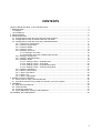
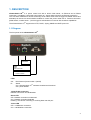
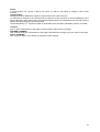
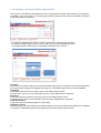
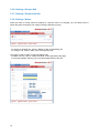
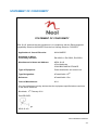
ePowerSwitch 1GR2 User guide Version 02 2011 www.neol.com © Copyright by NEOL S.A.S - 4 Rue Nationale, 67800 BISCHHEIM, France Printed in France All rights reserved. No part of this documentation, accompanying software or other components of the described product may be reproduced or transmitted in any form or by any means, electronic or mechanical, including photocopying and recording, for any purpose other than the personal use of the purchaser without the express written permission of NEOL S.A.S. This documentation, the ePowerSwitch 1GR2, its peripherals, accessories and accompanying software were produced with great care, yet errors are possible. NEOL S.A.S assumes no responsibility for errors within the documentation, the hardware or the software. NEOL S.A.S reserves the right to change programs or the documentation from time to time without informing the user, errors and omissions excepted. Trademarks Neol and ePowerSwitch are registered trademarks of NEOL S.A.S. All other brand names and product names used in this book are trade names, service marks, trademarks, or registered trademarks of their respective owners. 1 CONTENTS SAFETY INSTRUCTIONS: To be read before use! ...................................................................................... 3 1. DESCRIPTION .......................................................................................................................................... 4 1.1 Diagram ............................................................................................................................................... 4 1.2 Package list ......................................................................................................................................... 5 2. INSTALLATION ......................................................................................................................................... 6 3. CONFIGURATION .................................................................................................................................... 7 3.1. Configuration through the LAN using the Finder program ................................................................. 7 3.2. Configuration through an RS232 Terminal connection ...................................................................... 9 3.3. Configuration through the LAN using a standard Browser ............................................................... 10 3.3.1. General / IP configuration ...................................................................................................... 11 3.3.2. General / System time ............................................................................................................ 12 3.3.3. General / SNMP ..................................................................................................................... 13 3.3.4. General / Tools ....................................................................................................................... 14 3.3.5. Settings / Accounts................................................................................................................. 15 3.3.5.1 Settings / Accounts .................................................................................................... 15 3.3.5.2 Settings / Accounts / Hidden Page account............................................................... 17 3.3.6. Settings / Groups N/A............................................................................................................. 19 3.3.7. Settings / Peripherals N/A ...................................................................................................... 19 3.3.8. Settings / Rules ...................................................................................................................... 19 3.3.8.1. Settings / Rules - Schedule Rule .............................................................................. 21 3.3.8.2. Settings / Rules - Timer Rule .................................................................................... 23 3.3.8.3. Settings / Rules - Ping Monitoring Rule .................................................................... 25 3.3.8.4. Settings / Rules - Scan Monitoring Rule ................................................................... 27 3.3.9. Settings / Shutdowns.............................................................................................................. 29 3.3.10. Misc / Control Panel ............................................................................................................. 31 3.3.11. Misc / Rule Panel ................................................................................................................. 32 3.3.12. Misc / Log ............................................................................................................................. 33 3.3.13. Misc / Log Settings ............................................................................................................... 34 4. POWER OUTLET CONTROL ................................................................................................................. 35 4.1. via the Internet using a standard browser ........................................................................................ 35 4.1. through the network using simple commands in your own program ................................................ 36 5. APPENDIX............................................................................................................................................... 39 5.1. Ping and Scan Methods ................................................................................................................... 39 5.2. Technical Data.................................................................................................................................. 40 5.3. Commonly used Ports ...................................................................................................................... 40 5.4. Syslog Messages: Severity Level Definitions ................................................................................... 41 STATEMENT OF CONFORMITY................................................................................................................ 42 2 SAFETY INSTRUCTIONS: To be read before use! NOTE • The ePowerSwitch devices can only be installed by qualified people with the following installation and use instructions. The manufacturer disclaims all responsibility in case of a bad utilization of the ePowerSwitch devices and particularly any use with equipments that may cause personal injury or material damage. • This equipment is designed to be installed on a dedicated circuit that must have a circuit breaker or fuse protection. • The electrical power sockets used to plug the power cords of the ePowerSwitch devices must be close to the ePowerSwitch devices and easily accessible. • Check that the power cords, plugs and sockets are in good condition. • The ePowerSwitch devices can only be connected to three-wire 230 VAC (50-60Hz) sockets. • Always plug the ePowerSwitch devices into properly grounded power sockets (two poles plus ground). • Never exceed 10 Amp total load for the power outlet of an ePowerSwitch device. • The ePowerSwitch devices are intended for indoor use only. Do NOT install them in an area where excessive moisture or heat is present. • Always disconnect the power cord of the ePowerSwitch device if you want to intervene on the ePowerSwitch device or on the equipment powered from the ePowerSwitch device. • The power outlets of the ePowerSwitch devices are not circuit breakers! If you want to intervene on equipments connected to an ePowerSwitch device you must disconnect these equipments from the ePowerSwitch device. • Do NOT attempt to disassemble the ePowerSwitch devices, they contain potentially hazardous voltages. • The ePowerSwitch devices contain no user serviceable parts and repairs are to be performed by factory trained service personnel only. • Always use a shielded cable for the Ethernet connection. 3 1. DESCRIPTION ePowerSwitch*1GR2 is a power control unit with a built-in Web server, an Ethernet and a RS232 connection. It enables to control the power supply of 1 power outlet1s through an Ethernet connection. This unit offers additional IP device monitoring. It has a Real Time Clock to trigger scheduled actions and timestamp all events. Its serial interface enables to control the power outlet over a Terminal connection (KVM Switch, console server...) and to trigger a soft shutdown of a server with shutdown capabilities. The ePowerSwitch 1GR2 supports the HTTP, DHCP, Syslog, SNMP and SNTP protocols. 1.1 Diagram The front panel of the ePowerSwitch 1GR2 RJ45 Connector LEDs Status Status of the outlet SUB-D9F Connector Terminal connection LEDs Out PL Red. Status of power outlet 1 (On/Off) Status On = ePowerSwitch 1GR2 software is loaded and functional Off = power default 10/100 (RJ45 Connector) Network connection 10/100 Mbits/sec Green LED Off = Network connection not detected On = Network connection detected Flashing = the device is sending or receiving data over this port Yellow LED Off = 10 Mbits/sec connection On = 100 Mbits/sec connection 4 RS232 (SUB-D 9F Connector) Serial port RS232 with DB-9 female connector Pinout 2 = TxD 3 = RxD 5 = Gnd The back of the ePowerSwitch 1GR2 Power input 230 VAC – 10 Amp Power outlet Power outlet 230 VAC max 10 Amp 1.2 Package list The following items are included: 5 1 ePowerSwitch 1GR2 1 power cable, 230 V / 10 Amp, length 1.80 Meters 1 RJ45 M/M cable, 2 Meters 1 serial cable SUB-D 9 points M/F, 1.80 Meters 1 quick installation guide 1 CD with User Guide, Quick Start Guide and Windows configuration program 2. INSTALLATION Remark: Make sure that the ePowerSwitch 1GR2 is powered off. Connection instructions 1. Use a shielded RJ45 network cable to connect your ePowerSwitch 1GR2 to the network. 2. Use appropriated three-wire power cords (two poles plus ground) to connect your electrical device to the ePowerSwitch 1GR2 unit. 3. Plug the power cable into a grounded socket. The Status LED lights on to confirm that power is on. 4. You can now configure the ePowerSwitch 1GR2 by following the indications of the chapter "Configuration of the ePowerSwitch 1GR2". 6 3. CONFIGURATION To use the ePowerSwitch 1GR2 on your network, you must first configure its network parameters. Ask your network administrator for the parameters to use. There are three methods to configure the network parameters of the ePowerSwitch 1GR2: 3.1. Configuration through the LAN using the Finder program It is the simplest and fastest configuration method if you use Windows as operating system. It allows to configure your ePowerSwitch 1GR2 through your local network even if its network parameters are not compatible with those of your PC. 1. Start the Finder.exe program contained on the CD-ROM. 2. Open the File menu and choose SCAN (or click on the first left button in the tool bar) to discover the ePowerSwitch 1GR2 connected on your LAN. 3. Open the File menu and choose CONFIGURE (or click on the second left button in the tool bar) to configure the network parameters. This page enables to define all IP parameters of the ePowerSwitch 1GR2 device and displays the version of the Firmware. The HTTP protocol is enabled and the Finder program is authorized at factory settings. !!! To achieve the highest security level we suggest to disable the configuration using the Finder program after the first installation. 7 DHCP: Check this box is you want to obtain the IP address, the subnet mask and the default gateway for your ePowerSwitch 1GR2 via DHCP. Use of DHCP (Dynamic Host Configuration Protocol) requires a DHCP host to be set up on the network. IP Address: IP address of the ePowerSwitch 1GR2, default is 192.168.100.200. Subnet Mask: Subnet Mask of the ePowerSwitch 1GR2, default is 255.255.255.0. Gateway: Generally the address of your router, default is blank. DNS 1: Primary DNS (Domain Name Server), default is blank. DNS 2: Secondary DNS, default is blank. Port Number: Port number: default is 80 (HTTP). Version: Firmware version of the ePowerSwitch 1GR2 Finder authorized: The Network parameters of the ePowerSwitch 1GR2 can be configured through a Local Area Network using the provided Finder Program. It is a simple and fast configuration method if you use Windows as operating system. !!! The Finder Program is enabled as default value. For security reasons we suggest to disable the Finder program after the first configuration. 8 3.2. Configuration through an RS232 Terminal connection 1. Use the provided RS232 cable to connect the ePowerSwitch 1GR2 to an available serial port of your PC. 2. Run a Terminal program such as Windows HyperTerminal. 3. Configure the appropriate serial port @ 9.600, n, 8, 1 and no flow control. 4. On your computer, press <ENTER> until the menu appears on your screen. 5. Press the “M” on your keyboard and follow the menu to configure the network parameters of your ePowerSwitch 1GR2. Special commands (type /? or /Help) /initlog Clears the log file /initadminaccount Restores default administrator password /restorefactconf Restores to factory default settings /help /? Displays this help -----------------------------------------------------------NETWORK INTERFACE PARAMETERS: IP address on LAN is 192.168.100.200 LAN interface's subnet mask is 255.255.255.0 IP address of default gateway to other networks is 0.0.0.0 IP address of primary DNS server is 0.0.0.0 IP address of secondary DNS server is 0.0.0.0 MISCELLANEOUS: HTTP Port is 80 Finder program is enabled HARDWARE PARAMETERS: MAC Address is 00.13.F6.01.3C.80 ------------------------------------------------------------ Configuration menu 9 3.3. Configuration through the LAN using a standard Browser During the first installation, change temporarily the network settings of your PC according to the default network settings of the ePowerSwitch 1GR2. Factory network settings of the ePowerSwitch 1GR2: IP Address: 192.168.100.200 - Port: 80 Gateway: 255.255.255.0 1. Open your Web browser and type following IP address: http://192.168.100.200/sysadmin.htm 2. Enter the administrator name and password (default for both = admin) 3. The home page appears, allowing you to configure all settings of your ePowerSwitch 1GR2. 10 3.3.1. General / IP configuration This page enables you to define all the IP parameters of the ePowerSwitch 1GR2. DHCP Client enabled: Check this box is you want to obtain the IP address, the subnet mask and the default gateway for your ePowerSwitch 1GR2 via DHCP. Factory default setting for this option is disabled. Use of DHCP (Dynamic Host Configuration Protocol) requires a DHCP host to be set up on the network. IP Address: IP address of the ePowerSwitch 1GR2, default is 192.168.100.200. Subnet Mask: Subnet Mask of the ePowerSwitch 1GR2, default is 255.255.255.0. Default Gateway: Generally the address of your router, default is blank. Primary DNS Address: Primary DNS (Domain Name Server), default is blank Secondary DNS Address: Secondary DNS, default is blank Finder Program enabled: The Network parameters of the ePowerSwitch 1GR2 can also be configured through a Local Area Network using the provided Finder Program. It is a very simple and fast configuration method if you use Windows as operating system. The Finder Program is enabled as default value. !!!For security reasons we suggest to disable the Finder program after the first configuration. HTTP Port: Port number: default is 80. LOGOUT: Click "Logout" at the bottom of the page to exit the session without saving changes. DISCARD CHANGES: Click "Discard Changes" at the bottom of the page to discard all the changes you have made on this page. APPLY CHANGES: Click "Apply Changes" at the bottom of the page to save changes. 11 3.3.2. General / System time The system time of the ePowerSwitch 1GR2 is used for synchronizing scheduling actions and to timestamp SNMP traps, Syslog information and internal logs. The system time can be set manually with the browser time of the connected computer or can be automatically synchronized with one or two NTP timeservers. Current System Time: This field shows the current system time of the ePowerSwitch 1GR2. As the system time is displayed through the browser, a small difference (1 to 2 sec) can appear as compared to the exact hour. The system time is nevertheless correct. Use Browser Time: If you want to set the system time using the current Browser time of your PC, select this option and click on the "Set System Time" button. Use NTP Server: If you want to set the system time using an NTP timeserver, select this option, choose a refresh interval and enter the IP address of the timeserver you wish to use in the "Primary" field. The address of a second timeserver can be specified in the "Secondary" field. The secondary timeserver is optional and is used only if the primary timeserver is not available. You can enter either the hostname (in that case you must have specified a DNS server on the IP configuration page) or the IP address of an NTP server. NTP uses port 123/UDP. Time Zone: Set the time zone corresponding to your location. The system clock will subsequently show local time. Without setting this, the system clock will show UTC/GMT time. Setting a time zone is only relevant if you are synchronizing with an NTP server. Daylight Saving Time: If you want to set Daylight Saving dates, check this box and specify the date you want to use. LOGOUT: Click "Logout" at the bottom of the page to exit the session without saving changes. DISCARD CHANGES: Click "Discard Changes" at the bottom of the page to discard all the changes you have made on this page. APPLY CHANGES: Click "Apply Changes" at the bottom of the page to save changes. 12 3.3.3. General / SNMP The ePowerSwitch 1GR2 provides a built-in SNMP (Simple Network Management Protocol) agent, which enables you to manage the ePowerSwitch 1GR2 through SNMP-based network management systems. The ePowerSwitch 1GR2 MIB file enables to remotely read out the status of all power outlets and the values of all sensors (temperature, humidity, ambient light). It also enables to control individually all power outlets and all groups of power outlets. The MIB file is stored on the ePowerSwitch 1GR2 and can be downloaded from the General / Tools Page. SNMP enabled: Check this box if you want to enable the SNMP protocol. Contact: In this field, enter the name you want to give to the Contact field. The name can be from 1 to 64 characters long, and can contain alphanumeric characters. Default name is "contact". Name: In this field, enter the name you want to give to the Name field. The name can be from 1 to 64 characters long, and can contain alphanumeric characters. Default name is "name". Location: In this field, enter the name you want to give to the Location field. The name can be from 1 to 64 characters long, and can contain alphanumeric characters. Default name is "location". Read Community: In this field, enter the name you want to give to the Read Community field. The name can be from 1 to 64 characters long, and can contain alphanumeric characters. Default name is "public". Write Community: Check this box if you want to be able to control the power outlets through a MIB browser. In the following field, enter the name you want to give to the Write Community. The name can be from 1 to 64 characters long, and can contain alphanumeric characters. Default name is "private". Trap Community: Check this box if you want to configure the ePowerSwitch 1GR2 SNMP agent to send traps to a community. In the following field, enter the name you want to give to the Trap Community. The name can be from 1 to 64 characters long, and can contain alphanumeric characters. Default name is "trap". Trap Destination 1: Check this box and enter the primary SNMP Server address the traps will be sent to. Trap Destination 2: Check this box and enter the secondary SNMP Server address the traps will be sent to. LOGOUT: Click "Logout" at the bottom of the page to exit the session without saving changes. DISCARD CHANGES: Click "Discard Changes" at the bottom of the page to discard all the changes you have made on this page. APPLY CHANGES: Click "Apply Changes" at the bottom of the page to save changes. 13 3.3.4. General / Tools This page enables you to: - download and save the current settings of your ePowerSwitch 1GR2 on your PC, - upload an existing configuration file to your ePowerSwitch 1GR2, - restore the factory settings, - download the ePowerSwitch 1GR2 MIB file on your PC. Save: Click this button to save the current system settings onto your local hard drive. Load: Click this button and select a settings file you want to download to the ePowerSwitch 1GR2. Restore: Click this button if you want to restore the factory default settings. Save MIB: Click this button if you want to download the ePowerSwitch 1GR2 MIB file onto your local hard drive. LOGOUT: Click "Logout" at the bottom of the page to exit the session without saving changes. 14 3.3.5. Settings / Accounts 3.3.5.1 Settings / Accounts This page is used to create, activate, deactivate, modify and delete up to 40 accounts. - To activate or deactivate an account, check or uncheck the corresponding checkbox. - To modify an account, click on "Edit" next to the corresponding account. - To delete an existing account, click on "Delete" next to the corresponding account. - To create an account, click on "Add a New Account" on the right side of the page. A new page appears, allowing you to set all the parameters of the account. User Name: In this field, enter the name you want to give to the user. The name can be from 1 to 32 characters long, and can contain alphanumeric characters. Do not use quotes or special characters in labels! Password: In this field, enter the password you want to give to the user. The password can be from 4 to 32 characters long, and can contain alphanumeric characters. Confirm Password: In this field, enter the password again. IP Address Control: Check this checkbox and specify an IP address or a range of IP address if you want to restrict the access of this account. 15 Device: In this drop-down list, choose a device from which you want to add Inputs or Outputs to the current account. Inputs/Outputs: This field is used to add/remove Inputs or Outputs to/from the current account. To add Inputs or Outputs to the current account, press the Ctrl key and click on the Inputs/Outputs of the device selected in the previous field. The selected Inputs/Outputs are marked dark blue and their IDs are listed at the right side of the Input/Output field. The ePowerSwitch 1GR2 supports number of peripherals which are clearly identified by specific ID Codes. LOGOUT: Click "Logout" at the bottom of the page to exit the session without saving changes. DISCARD CHANGES: Click "Discard Changes" at the bottom of the page to discard all the changes you have made on this page. APPLY CHANGES: Click "Apply Changes" at the bottom of the page to save changes. 16 3.3.5.2 Settings / Accounts / Hidden Page account This account is intended for developers who want to implement the power outlet control in own programs. If activated, they can access to a special page named hidden.htm and control individually the power outlets using simple commands. - To activate or deactivate this account, check or uncheck the corresponding checkbox. - To modify the Hidden page account, click on "Edit" next to the corresponding account. A new page appears, allowing you to set all the parameters of the account. Activated This check box must be checked to activate the Hidden Page Account. It enables to deactivate temporarily this account while keeping all its settings for a later use. The Hidden Page Account cannot be deleted. User Name In this field, enter the name you want to give to the Hidden Page Account. The user name can be up to 32 characters long and contain alphanumeric characters. Password In this field, enter the password you want to give to the Hidden Page Account. The password can be up to 32 characters long and contain alphanumeric characters. Confirm Password In this field, enter the password again for confirmation. IP Address Control Network security can be increased by IP address filtering. Check this checkbox and specify an IP address or a range of IP addresses which has the right to access to the Hidden Page Account. 17 Device In this drop-down list, choose the device from which one you want to add an Inputs to the current account. - Only properly connected devices or devices which already have been connected to the Power Switch appears in this field. - Each peripheral is clearly identified by its own ID followed by the name given during the configuration. Behind the ID can appear a character between brackets which has following meaning: - "!" means that the corresponding device is properly connected to the Power switch but not activated. To activate it, go to the "Settings/Peripherals" page. - "X" means that the corresponding device has already been connected to the Power switch but is currently no longer connected to the Power Switch. Inputs/Outputs - This field is used to add/remove Inputs or Outputs to/from the current account. - To add an Input or Output to the current account, select the Input / Output you want to add in the left field and click on the Arrow button, the selected Input / Output will then appear in the right field. - To remove an Input or Output from the current account, select the Input / Output you want to remove in the right field and click on the Arrow button, the selected Input / Output will then appear in the left field. Accessing to the Hidden Page Account To be able to access to the Hidden Page, you must have configured the Hidden Page Account and activated it. For the first tests, simply check the Activated check box, start your browser and type into your browser's address bar the IP address of your power switch followed by the name of the hidden page. Example: if the IP address of your Power Switch is 192.168.100.200, type in: http://192.168.100.201/hidden.htm followed by <ENTER>. Your Web browser will now display: Hidden Page 21 Dec 2010 01:50:03 Version: 2.1.0.0 Controlling Power Outlet Only Power Outlets which have been selected can be controlled over the Hidden Page. To select Power Outlets, go to the "Settings/Accounts" page and edit the Hidden Page Account. In the Inputs/Outputs field, selected the Power Outlets you want to control and click on the Arrow button next to the Inputs/Outputs field. The selected Power outlets appear in the right field, click on Apply Change to validate the configuration. Example: if you have selected the power Outlet and the IP address of your Power Switch is 192.168.100.200, type in: http://192.168.100.201/hidden.htm followed by <ENTER>. Your Web browser will now display: Hidden Page 21 Dec 2010 02:29:01 Version: 2.1.0.0 M0:O1 On The Power Outlet supports 3 commands: On, Off and Restart using following syntax: M0:Ox ON , OFF , RESTART M0: ID of your Power Switch Ox: Outlet number of your Power Switch ON: ON command OFF: OFF command RESTART: Restart command The first command must be preceded by a "?" Commands can be concatenated using the character "&" Commands can be specified in upper case, lower case or mixed case 18 3.3.6. Settings / Groups N/A 3.3.7. Settings / Peripherals N/A 3.3.8. Settings / Rules Rules are used to control actions according to a specific event. For example, you can define rules to switch the power outlet OFF from Friday evening to Monday morning. - To remove an existing rule, click on "Delete" of the corresponding rule. - To modify a rule, click on "Edit" of the corresponding rule. This page is used to create, modify and delete rules. - To add a new rule, click on "Add a New Rule" on the right side of the page. A new page appears, allowing you to set all the parameters of the rule. 19 A total of 32 rules can be created and there are 4 different types of rules: 1. Schedule Rule: This rule is used to trigger user-specified actions according to a defined time table. This rule can be used to: - execute once defined actions at specified time and weekday(s). In this case you must only specify the start time and the weekday(s), - execute repeatedly defined actions during a given time. In this case you must specify the start time, the interval on which the rule has to be repeated and the end time. Examples: - The rule can be used to restart a power outlet at regular interval during a given time. - The rule can be used to send a Syslog message at regular interval during a given time. 2. Timer Rule: This rule can be used to trigger user-specified actions according to a defined time table. This rule can be used to switch On or Off a power outlet at specified time and weekday(s) for a specified time. You must define the start time, the weekday(s) and the stop time. Example: - The rule can be used to switch On a device every Monday and Friday from 8:00 AM (Start Time) and switch it automatically off every Monday and Friday at 05:00 PM (Stop Time) 3. Ping Monitoring Rule: This rule is used to control actions according to the response to a Ping command. This rule can be used to check if a computer or any IP device is connected to the network. If the host doesn't reply, the ePowerSwitch can automatically restart the powered device. 4. Scan Monitoring Rule: This rule is used to control actions according to the response to a Scan command. This rule can be used to check if a specific protocol is available on a. If the connection is not possible, ePowerSwitch can automatically restart the powered device. 20 3.3.8.1. Settings / Rules - Schedule Rule This rule can be used to trigger user-specified actions according to a defined time table. The schedule rule is weekday based and the administrator can declare, for each weekday, a start time, an end time and after what time the rule should be repeated. Activated This check box must be checked to activate the Rule and enables to deactivate temporarily a rule while keeping all its settings for a later use. Rule ID: The ePowerSwitch 1GR2 automatically creates an ID Code to clearly identify each rule. All the ID Codes used to identify rules start with the letter "R" followed by a number from 1 to 32. If you delete a rule in the middle of the Rule list, the number of this rule will only be used again if no other rule is available. Rule Name: In this field, enter the name you want to give to the rule. The name can be from 1 to 32 characters long, and can contain alphanumeric characters. Do not use quotes or special characters in labels! Rule Color: In this field, select one of the 48 standard colours you want to use to highlight the rule when executed. To use own colours, just type in the Hex value of the colour you want. The Rule highlighting allows to quickly identify the triggered rule when displayed in the Rule Panel page or in a special user's page. Rule Type: In this drop-down list, choose Schedule Rule then configure the event and the actions to perform. Configuring the Event Schedule Action: Here you can define the time when the rule has to be executed. In the Drop-Down lists choose the time and below, check one or more day boxes. Start Time Defines what time the rule starts. Repeat Time Defines the time period in which the rule repeats. Repeat Time cannot be set to zero. 21 Stop Time Defines what time the rule ends. - End Time must be greater than or equal to Start Time. - If the rule has to be executed only once at the selected weekday, enter the same value for Start Time and End Time. - If the rule has to be executed 24 hours at the selected weekday, Start Time must be 1 minute later than EndTime. Applicable weekday Defines which day(s) the rule has to be executed. Type of Action For the Event defined above, you can choose and configure following actions: Set Power Outlet: Check this box and in the corresponding drop-down list, choose the power outlet the rule will apply to. In the next corresponding drop-down list, choose the action to execute. The power outlet can be switched On/Off and restarted. If you choose "restart" you will also be able to define a restart delay between 0 and 65535 seconds. - If you choose 0 second, the delay will be the delay defined in the ePowerSwitch power outlet settings. - If you choose a delay different from 0, the delay will replace the delay defined in the ePowerSwitch power outlets settings. Send Syslog Message: This type of action can be configured only if you have already created at least one destination Syslog Server (Misc/Log Settings Tab). Check this box if you want to send a message to a Syslog server. In the following drop-down lists choose the facility and the severity of the message to send. The address of the Syslog server has to be defined in the "Log Settings Page". Send Trap Message: This type of action can be configured only if you have already specified at least a destination SNMP Server (General/SNMP Tab). Check this/these box(es) and specify one or two SNMP addresses in the corresponding field if you want to send SNMP messages to one or two SNMP Servers. Syslog / Trap Message: This field can be used only if you have already specified at least one destination Syslog Server (Misc/Log Settings Page) or one destination SNMP Server (General/SNMP Page. Up to 255 characters may be entered in this free text field. The text will appear in the Syslog and the Trap. The message can be completed with the status of an input (a power supply or door contact for example) or the value of a sensor (a temperature sensor for example). For this, simply enter, between two percent characters, the ID of the corresponding input device (for details see § 5.1 Sending status and values using rules). LOGOUT: Click "Logout" at the bottom of the page to exit the session without saving changes. DISCARD CHANGES: Click "Discard Changes" at the bottom of the page to discard all the changes you have made on this page. APPLY CHANGES: Click "Apply Changes" at the bottom of the page to save changes. 22 3.3.8.2. Settings / Rules - Timer Rule This rule can be used to trigger some actions according to a defined time table. For instance, you could create a rule to switch OFF a Power Outlet every Friday at 6 PM and create another rule to switch the Power Outlets ON again every Monday at 8 AM. Activated This check box must be checked to activate the rule. It enables to deactivate temporarily a rule while keeping all its settings for a later use. Rule ID The Power Switch automatically creates an ID Code to clearly identify each rule. These codes start with the letter "R" followed by a number. Rule Name In this field, enter the name you want to give to the rule. The name can be from 1 to 32 characters long, and can contain alphanumeric characters. Do not use quotes or special characters in labels! Rule Color: In this field, select one of the 48 standard colours you want to use to highlight the rule when executed. To use own colours, just type in the Hex value of the colour you want. The Rule highlighting allows to quickly identify the triggered rule when displayed in the Rule Panel page or in a special user's page. Rule Type In this Drop-Down list, choose Schedule Rule. Rules are used to control actions according to a specific event. To create a rule, you will first have to configure the chosen event and then to choose the actions to perform. Configuring the Event Timer Action Start Time Defines what time the rule starts. Stop Time Defines what time the rule ends. Applicable weekday Defines which day(s) the rule has to be executed. Type of Action For the Event defined above, you can choose and configure following actions: 23 Set Power Outlet: Check this box and in the corresponding drop-down list, choose the power outlet the rule will apply to. In the next corresponding drop-down list, choose the action to execute. Each power outlet can be switched On/Off and restarted. If you choose "restart" you will also be able to define a restart delay between 0 and 65535 seconds. - If you choose 0 second, the delay will be the delay defined in the ePowerSwitch power outlets settings. - If you choose a delay different from 0, the delay will replace the delay defined in the ePowerSwitch power outlets settings. Send Syslog Message: This type of action can be configured only if you have already created at least one destination Syslog Server (Misc/Log Settings Tab). Check this box if you want to send a message to a Syslog server. In the following drop-down lists choose the facility and the severity of the message to send. The address of the Syslog server has to be defined in the "Log Settings Page". Send Trap Message: This type of action can be configured only if you have already specified at least a destination SNMP Server (General/SNMP Tab). Check this/these box(es) and specify one or two SNMP addresses in the corresponding field if you want to send SNMP messages to one or two SNMP Servers. Syslog / Trap Message: This field can be used only if you have already specified at least one destination Syslog Server (Misc/Log Settings Page) or one destination SNMP Server (General/SNMP Page. Up to 255 characters may be entered in this free text field. The text will appear in the Syslog and theTrap. The message can be completed with the status of an input (a power supply or door contact for example) or the value of a sensor (a temperature sensor for example). For this, simply enter, between two percent characters, the ID of the corresponding input device (for details see § 5.1 Sending status and values using rules). LOGOUT: Click "Logout" at the bottom of the page to exit the session without saving changes. DISCARD CHANGES: Click "Discard Changes" at the bottom of the page to discard all the changes you have made on this page. APPLY CHANGES: Click "Apply Changes" at the bottom of the page to save changes. 24 3.3.8.3. Settings / Rules - Ping Monitoring Rule This rule can be used to check if a computer or any IP device is connected to the network. It sends ping packets and listens for replies from the specific host. If the host doesn't reply, the ePowerSwitch 1GR2 can automatically switch the powered device off and after a specified delay, switch it again on (for details see Ping & Scan Method). Activated This check box must be checked to activate the Rule and enables to deactivate temporarily a rule while keeping all its settings for a later use. Rule ID: The ePowerSwitch 1GR2 automatically creates an ID Code to clearly identify each rule. All the ID Codes used to identify rules start with the letter "R" followed by a number from 1 to 32. If you delete a rule in the middle of the Rule list, the number of this rule will only be used again if no other rule is available. Rule Name: In this field, enter the name you want to give to the rule. The name can be from 1 to 32 characters long, and can contain alphanumeric characters. Do not use quotes or special characters in labels! Rule Color: In this field, select one of the 48 standard colours you want to use to highlight the rule when executed. To use own colours, just type in the Hex value of the colour you want. The Rule highlighting allows to quickly identify the triggered rule when displayed in the Rule Panel page or in a special users page. Rule Type: In this drop-down list, choose Ping Monitoring Rule then configure the event and the actions to perform. Configuring the Event Monitored device address: In this field enter the IP address of the IP device that you want to monitor using the Ping command. Wait Time for Answer: In this field, define the delay in seconds for the Answer Timeout. The delay can be set between 1 and 10 seconds. Interval between Requests: In this field, define the delay in seconds between ping commands sent to the IP device to monitor. The delay can set between 30 and 65535 seconds. Number of unsuccessful Requests before Action: In this field, define the number of Ping commands to be sent to the IP device before executing the actions. The number can be set between 1 and 65535 seconds. 25 Delay before First Request after Action: In this field, define the time in seconds before restarting the monitoring after the reboot action. The delay can be set between 30 and 65535 seconds. Maximum Number of Actions In this field, define the maximum number of actions. The number can be set between 0 and 255. Type of Actions: For the Event defined above, you can choose and configure following actions: Set Power Outlet: Check this box and in the corresponding drop-down list, choose the power outlet the rule will apply to. In the next corresponding drop-down list, choose the action to execute. Each power outlet can be switched On/Off and restarted. If you choose "restart" you will also be able to define a restart delay between 0 and 65535 seconds. - If you choose 0 second, the delay will be the delay defined in the ePowerSwitch power outlets settings. - If you choose a delay different from 0, the delay will replace the delay defined in the ePowerSwitch power outlets settings. Send Syslog Message: This type of action appears and can be configured only if you have already created at least one destination Syslog Server (Misc/Log Settings Tab). Check this box if you want to send a message to a Syslog server. In the following drop-down lists choose the facility and the severity of the message to send. The address of the Syslog server has to be defined in the "Log Settings Page". Send Trap Message This type of action appears and can be configured only if you have already specified at least a destination SNMP Server (General/SNMP Tab). Check this/these box(es) and specify one or two SNMP addresses in the corresponding field if you want to send SNMP messages to one or two SNMP Servers. Syslog / Trap Message This field can be used only if you have already configured at least one destination Syslog Server (Misc/Log Settings Page). Up to 255 characters may be entered in this free text field. The text will appear in the Syslog and the Trap. LOGOUT: Click "Logout" at the bottom of the page to exit the session without saving changes. DISCARD CHANGES: Click "Discard Changes" at the bottom of the page to discard all the changes you have made on this page. APPLY CHANGES: Click "Apply Changes" at the bottom of the page to save changes. 26 3.3.8.4. Settings / Rules - Scan Monitoring Rule This rule can be used to check if a specific protocol is available on a server (for example HTTP, FTP, Telnet, POP...). If the connection is possible, ePowerSwitch 1GR2 knows that a server program is running there. If the connection is not possible, ePowerSwitch 1GR2 can automatically switch the powered device off and, after a specified delay, switch it again on (for details see Ping & Scan Method). Activated This check box must be checked to activate the Rule and enables to deactivate temporarily a rule while keeping all its settings for a later use. Rule ID: The ePowerSwitch 1GR2 automatically creates an ID Code to clearly identify each rule. All the ID Codes used to identify rules start with the letter "R" followed by a number from 1 to 32. If you delete a rule in the middle of the Rule list, the number of this rule will only be used again if no other rule is available. Rule Name: In this field, enter the name you want to give to the rule. The name can be from 1 to 32 characters long, and can contain alphanumeric characters. Do not use quotes or special characters in labels! Rule Color: In this field, select one of the 48 standard colours you want to use to highlight the rule when executed. To use own colours, just type in the Hex value of the colour you want. The Rule highlighting allows to quickly identify the triggered rule when displayed in the Rule Panel page or in a special users page. Rule Type: In this drop-down list, choose Scan Monitoring Rule then configure the event and the actions to perform. Configuring the Event Monitored Device Address: In this field, enter the IP address of the IP device that you want to monitor using the Scan command. In the "Port to scan" field, enter the port number you want to monitor. The value can be set between 1 and 65535. Wait Time for Answer: In this field, define the delay in seconds for the Answer Timeout. The delay can be set between 1 and 10 seconds. Interval between Requests: In this field, define the delay between the scan commands sent to the IP device. The delay can be set between 30 and 65535 seconds. 27 Number of unsuccessful Requests before Action: In this field, define the number of Port scanning commands to be sent to the IP device before executing the actions. The number can be set between 1 and 65535 seconds. Delay before First Request after Action: In this field, define the time in seconds before restarting the monitoring after the reboot action. The delay can be set between 30 and 65535 seconds. Maximum Number of Actions In this field, define the maximum number of actions. The number can be set between 0 and 255. Configuring the Actions For the Event defined above, you can choose and configure following actions: Set Power Outlet: Check this box and in the corresponding drop-down list, choose the power outlet the rule will apply to. In the next corresponding drop-down list, choose the action to execute. Each power outlet can be switched On/Off and restarted. If you choose "restart" you will also be able to define a restart delay between 0 and 65535 seconds. - If you choose 0 second, the delay will be the delay defined in the ePowerSwitch power outlets settings. - If you choose a delay different from 0, the delay will replace the delay defined in the ePowerSwitch power outlets settings. Send Syslog Message: This type of action can be configured only if you have already created at least one destination Syslog Server (Misc/Log Settings Tab). Check this box if you want to send a message to a Syslog server. In the following drop-down lists choose the facility and the severity of the message to send. The address of the Syslog server has to be defined in the "Log Settings Page". Send Trap Message: This type of action can be configured only if you have already specified at least a destination SNMP Server (General/SNMP Tab). Check this/these box(es) and specify one or two SNMP addresses in the corresponding field if you want to send SNMP messages to one or two SNMP Servers. Syslog / Trap Message: This field can only be used if you have already specified at least one destination Syslog Server (Misc/Log Settings Page) or one destination SNMP Server (General/SNMP Page). Up to 255 characters may be entered in this free text field. The text will appear in the Syslog and the Trap. LOGOUT: Click "Logout" at the bottom of the page to exit the session without saving changes. DISCARD CHANGES: Click "Discard Changes" at the bottom of the page to discard all the changes you have made on this page. APPLY CHANGES: Click "Apply Changes" at the bottom of the page to save changes. 28 3.3.9. Settings / Shutdowns This power switch supports shutdown facilities of 1 server via its Serial RS232 interface. - To remove an existing Shutdown association, click on "Delete" of the corresponding rule. - To modify a Shutdown rule, click on "Edit" of the corresponding rule. This page is used to create, modify and delete a Shutdown Association. Click on "Add a New Shutdown" on the right side of the page. A new page appears, allowing you to set all the parameters of the rule. Activated This check box must be checked to activate the Shutdown Rule and enables to deactivate temporarily a rule while keeping all its settings for a later use. Shutdown Association ID The Power Switch automatically creates ID codes to clearly identify each rule. The codes used to indentify Shutdown Rules start with the letters "SDA" followed by a number. Shutdown Association Name In this field, enter the name you want to give to the rule. The name can be from 1 to 32 characters long, and can contain alphanumeric characters. Do not use quotes or special characters in labels! Delay after Shutdown before continue In this field, specify a delay after which the associated power outlet will be switch to off. Shutdown Device In this Drop-Down list, choose the device which will be used to trigger the Shutdown action. If the Power Switch is used as stand-alone unit, this Drop-Down list will only show the Power Switch itself. 29 Shutdown Outputs In this field, choose the output which will be used to trigger the Shutdown. - To select an output, select the output you want to add in the left field and click on the Arrow button, the output will then appear in the right field. - To remove the selected output, select this output in the right field and click on the Arrow button, the output will then appear in the left field. Device In this Drop-Down list, choose the device of which the power outlet will be used to trigger the Shutdown action. If the Power Switch is used as stand-alone unit, this Drop-Down list will only show the Power Switch itself. Power Outlets In this field, choose the Power Outlet will be used to trigger the Shutdown. - To select a Power Outlet, select the Power outlet you want to add in the left field and click on the Arrow button, the Power Outlet will then appear in the right field. - To remove the selected Power Outlet, select this Power Outlet in the right field and click on the Arrow button, the Power Outlet will then appear in the left field. LOGOUT: Click "Logout" at the bottom of the page to exit the session without saving changes. DISCARD CHANGES: Click "Discard Changes" at the bottom of the page to discard all the changes you have made on this page. APPLY CHANGES: Click "Apply Changes" at the bottom of the page to save changes. 30 3.3.10. Misc / Control Panel This page is very helpful for the administrator because it gives a complete overview. At a glance, the administrator can check the status of the power outlet. 31 3.3.11. Misc / Rule Panel This page shows all the rules the administrator has created and activated. The rules which have been executed can also be highlighted in different colours according to the emergency of the action. The highlight colours can be customized during the creation of the rule (Settings/Rules Page). For supervision purpose, the administrator can create special accounts which display only some specific rules. In the example below, the user Bill has the possibility to supervise 2 rules and to see on a glance the rules which have been triggered. The page is automatically refreshed every 10 seconds. Unlike a standard session, the web server of the ePowerSwitch 1GR2 won’t automatically close this kind of session. Opening many sessions of this affects the performances of the web server. 32 3.3.12. Misc / Log The log file keeps a running log of events and activities occurring on the device. The logs are automatically cleared when the device is rebooted. The file will display 10 recent logs. 33 3.3.13. Misc / Log Settings This page allows you to configure the logs. The Log file is used by the system to record actions, warnings, errors and problems. It is often quite useful to discover the causes of tricky problems. The messages recorded in the log file and sent as copy to a Syslog server are classified into 8 severity levels (Emergency, Alert, Critical, Error, Warning, Notice, Informational and Debug). Primary Syslog Server: Server Address" and enter the address of the Syslog Server you wish to use. You can enter either the hostname or the IP address of a Syslog server. The Syslog uses port 443/UDP. If you want to enable the Power Switch to send messages to a Syslog Server, check the box "Syslog Note: if you use a hostname, it is important that the system can resolve the hostname locally and so you need to configure a Default Gateway and at least one DNS Server on the Network Settings Page (General/IP Configuration page). Secondary Syslog Server: In this field you can define the IP Address of a secondary Syslog Server. You can enter either the hostname or the IP address of a Syslog server. LOGOUT: Click "Logout" at the bottom of the page to exit the session without saving changes. DISCARD CHANGES: Click "Discard Changes" at the bottom of the page to discard all the changes you have made on this page. APPLY CHANGES: Click "Apply Changes" at the bottom of the page to save changes. 34 4. POWER OUTLET CONTROL 4.1. via the Internet using a standard browser 1. Start your Web browser and type the IP address of your ePowerSwitch 1GR2. The browser displays the authentication dialog box. 2. Enter a user name and its corresponding password. The status of the ePowerSwitch 1GR2 is displayed. 3. In the drop-down list, choose the power control unit you want to control or the rule for which you want to know the status. The ON button allows you to switch ON the power outlet. The OFF button allows you to switch OFF the power outlet. The RESTART button allows you to switch OFF the power outlet. The power outlet will then be automatically switched ON after the delay defined by the administrator (see Settings / power outlet Page). If you log in as system administrator, you will be able to control the power outlet and display the status of the rules. If you log in as a user (ePowerSwitch 1GR2 handles up to 40 accounts), you will be able to control the power outlet and display the status the rules for which you have the rights. 35 4.1. through the network using simple commands in your own program Developers who want to implement the power outlet control in own programs can access to a special page named hidden.htm and control individually the power outlets using simple commands. To configure the Hidden Page Account, go to Settings / Accounts. - To activate or deactivate this account, check or uncheck the corresponding checkbox. - To modify the Hidden page account, click on "Edit" next to the corresponding account. A new page appears, allowing you to set all the parameters of the account. Activated This check box must be checked to activate the Hidden Page Account. It enables to deactivate temporarily this account while keeping all its settings for a later use. The Hidden Page Account cannot be deleted. User Name In this field, enter the name you want to give to the Hidden Page Account. The user name can be up to 32 characters long and contain alphanumeric characters. Do not use quotes or special characters in labels! Password In this field, enter the password you want to give to the Hidden Page Account. The password can be up to 32 characters long and contain alphanumeric characters. Confirm Password In this field, enter the password again for confirmation. IP Address Control Network security can be increased by IP address filtering. Check this checkbox and specify an IP address or a range of IP addresses which has the right to access to the Hidden Page Account. 36 Device In this drop-down list, choose the device from which one you want to add Inputs or Outputs to the current account. - Only properly connected devices or devices which already have been connected to the Power Switch appears in this field. - Each peripheral is clearly identified by its own ID followed by the name given during the configuration. Behind the ID can appear a character between brackets which has following meaning: - "!" means that the corresponding device is properly connected to the Power switch but not activated. To activate it, go to the "Settings/Peripherals" page. - "X" means that the corresponding device has already been connected to the Power switch but is currently no longer connected to the Power Switch. Inputs/Outputs - This field is used to add/remove Inputs or Outputs to/from the current account. - To add an Input or Output to the current account, select the Input / Output you want to add in the left field and click on the Arrow button, the selected Input / Output will then appear in the right field. - To remove an Input or Output from the current account, select the Input / Output you want to remove in the right field and click on the Arrow button, the selected Input / Output will then appear in the left field. Accessing to the Hidden Page Account To be able to access to the Hidden Page, you must have configured the Hidden Page Account and activated it. For the first tests, simply check the Activated check box, start your browser and type into your browser's address bar the IP address of your power switch followed by the name of the hidden page. Example: if the IP address of your Power Switch is 192.168.100.200, type in: http://192.168.100.201/hidden.htm followed by <ENTER>. Your Web browser will now display: Hidden Page 21 Dec 2010 01:50:03 Version: 2.1.0.0 Controlling Power Outlets Only Power Outlets which have been selected can be controlled over the Hidden Page. To select Power Outlets, go to the "Settings/Accounts" page and edit the Hidden Page Account. In the Inputs/Outputs field, selected the Power Outlets you want to control and click on the Arrow button next to the Inputs/Outputs field. The selected Power outlets appear in the right field, click on Apply Change to validate the configuration. Example: if you have selected the power Outlet and the IP address of your Power Switch is 192.168.100.200, type in: http://192.168.100.201/hidden.htm followed by <ENTER>. Your Web browser will now display: Hidden Page 21 Dec 2010 02:29:01 Version: 2.1.0.0 M0:O1 On The Power Outlet supports 3 commands: On, Off and Restart using following syntax: M0:Ox ON , OFF , RESTART M0: ID of your Power Switch Ox: Outlet number of your Power Switch ON: ON command OFF: OFF command RESTART: Restart command 37 The first command must be preceded by a "?" Commands can be concatenated using the character "&" Commands can be specified in upper case, lower case or mixed case Example: if you want to switch to OFF the Power Outlet #1, type in: http://192.168.100.201/hidden.htm?M0:O1=OFF Your Web browser will now display: Hidden Page 21 Dec 2010 02:42:08 Version: 2.1.0.0 M0:O1 Off 38 5. APPENDIX 5.1. Ping and Scan Methods ePowerSwitch 1GR2 has two methods to check whether an IP equipment (PC, server, router, Webcam...) is still alive: Address Pinging: The first method uses the well-known Ping command whereby a request is sent to a specific IP address. The Ping command, which is an echo request, enables you to determine through an ICMP protocol (Internet Control Message Protocol) if an IP device is available on the network. If the system reacts to this request, ePowerSwitch 1GR2 knows that the TCP/IP connection is established. If the system does not react to one or several requests, ePowerSwitch 1GR2 can automatically switch the device off and after a specified delay switch it again on (Reboot function). Port Scanning: The second method uses the Port Scan command to test a specific TCP/IP port. In other words, this command allows you to find out if a specific protocol is available on a server (for example HTTP, FTP, Telnet, POP...). ePowerSwitch 1GR2 simply tries to connect to a specific server port. If the connection is possible, ePowerSwitch 1GR2 knows that a server program is running there. If the connection is not possible, ePowerSwitch 1GR2 can automatically switch the device off and after a specified delay switch it again on (Reboot function). - The Supervision function works only if the ePowerSwitch 1GR2 is connected to the LAN. - The Ping and Scan functions can be used separately or together. - The network route between ePowerSwitch 1GR2 and the IP device you wish to supervise should be as direct as possible, so do not use unnecessary routers and complex wiring between them. A problem on a router or the wiring could reboot the IP device to supervise. - Execute several Pings and/or Scans before running the Reboot function. It could be possible that the IP device doesn't respond although it is still working. - Choose a realistic supervision cycle. One second is possible, however it's not necessary to overload the network with Ping and Scan requests. Recommended values: - Interval between Requests: 10 sec or more - Number of unsuccessful Requests before Reboot: 3 or more - Delay before Reboot: 10 sec or more - Delay before restarting monitoring after Reboot: 120 sec or more 39 5.2. Technical Data Network standards: IEEE 802.3, 10 / 100 BASE-T Network protocols: TCP/IP, HTTP Network connection: RJ-45 connector for STP CAT5 Max. network cable length 100 meters Serial connection: RS232, SUB-D 9 female Operating temperature: 0°C to +40°C Operating humidity: 10% to 80% RH (not condensing) Dimensions (LxDxH): 185 x 103 x 43 mm Weight: 1 kg Approvals: CE, EN 60950-1, EN 55022, EN 55024 5.3. Commonly used Ports TCP 80: UDP 123: UDP 161: UDP 162: UDP 514: This port is used for http connections. This port is used to allow time synchronization over NTP (Network Time Protocol). This port is used for SNMP Requests. This port is used for SNMP Traps. This port is used to deliver Syslog messages. 40 5.4. Syslog Messages: Severity Level Definitions The Emergency level is the most severe type of message generated by ePowerSwitch 1GR2 and the Debug severity level is the least severe one. Severity Level 0, Emergency: The following messages appear at severity 0: - Continuous error! Severity Level 1, Alert: The following messages appear at severity 1: - Settings have been reinitialized through the serial connection - ePowerSwitch 1GR2 does not respond Severity Level 2, Critical: The following messages appear at severity 2: - "file" config corrupted: restoring default values Severity Level 3, Error: ePowerSwitch 1GR2 doesn't generate Severity Level 3. Severity Level 4, Warning: The following messages appear at severity 4: - Settings have been changed through the serial connection - Settings have been changed through the network by User "name" Severity Level 5, Notice: The following messages appear at severity 5: - System has been restarted through the serial connection - Power Supply restored - Rule (number) : Outlet (number) has been switched ON Severity Level 6, Informational: The following messages appear at severity 6: - System has been started - Date & Time have been synchronized to a Network Time Server - User "name" : Outlet (number) has been switched ON - Session opened by user "name" Severity Level 7, Debug: ePowerSwitch 1GR2 doesn't generate Severity Level 7. 41 STATEMENT OF CONFORMITY STATEMENT OF CONFORMITY NEOL S.A.S. declares that this equipment is in compliance with the Electromagnetic Compatibility Directive 89/336/EEC and the Low Voltage Directive 73/23/EEC Application of Council Directive: 2004/108/EEC Standards to Which Conformity declared: EN 60950-1, EN 55022, EN 55024 Manufacturer's Name and Address: NEOL S.A.S 4 Rue Nationale 67800 BISCHHEIM -FRANCE Type of Equipment: Power distribution and control unit Type Designation: ePowerSwitch 1GR2 Reference: ePowerSwitch 1GR2 Years of Manufacture: 2011 We, the undersigned, hereby declare that the equipment specified above conforms to the above directives. Bischheim, 17th February 2011 Paul REYSER, General Manager NEOL S.A.S. All modifications reserved 42