1
COPPER BOILERS
FOR HYDRONIC HEATING
AND HOT WATER SUPPLY
•
•
•
•
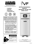
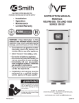
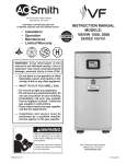
Instruction Manual
GB/GW-300, 400, 500, 650, 750
SERIES 400, 401, 402, 403, 404, 405
Installation
Operation
Maintenance
Limited Warranty
2-STAGE UNITS
Tha
u
o
Y
nk
for buying this
cost efficient, high recovery unit
from A. O. Smith Water Products Company
Please read through this informative manual and
pay special attention to the following:
WARNING: If the information in this
manual is not followed exactly, a fire or
explosion may result causing property
damage, personal injury or loss of life.
ROUGH-IN DIMENSIONS/CAPACITIES PAGES 2 - 4
"FOREWORD" ON PAGE 5
— Do not store or use gasoline or other
flammable vapors and liquids in the
vicinity of this or any other appliance.
"FEATURES" ON PAGES 6 - 7
"VENTING" ON PAGES 8 - 12
"GAS CONNECTIONS" 11 - 13
— WHAT TO DO IF YOU SMELL GAS:
"INSTALLATION INSTRUCTIONS" ON PAGES 5 - 13
• Do not try to light any appliance.
• Do not touch any electrical switch;
do not use any phone in your
building.
• Immediately call your gas supplier
from a neighbor’s phone. Follow the
gas supplier’s instructions.
• If you cannot reach your gas
supplier, call the fire department.
"WIRING DIAGRAM/SCHEMATIC" ON PAGES 14 - 15
"LIGHTING AND OPERATING" ON PAGES 19 - 20
"EMC5000 INSTRUCTIONS" ON PAGES 20 - 27
"SYSTEM EQUIPMENT INSTALLATION" PAGES 29 - 33
"TROUBLE SHOOTING" ON PAGES 27 - 28
"GENERAL MAINTENANCE" ON PAGES 34 - 35
"START-UP INSTRUCTIONS" ON PAGES 37 - 38
"LIMITED WARRANTY" ON PAGE 39
— Installation and service must be
performed by a qualified installer,
service agency or the gas supplier.
CAUTION
TEXT PRINTED OR OUTLINED IN RED CONTAINS
INFORMATION RELATIVE TO YOUR SAFETY. PLEASE
READ THOROUGHLY BEFORE INSTALLING AND USING
THIS APPLIANCE.
PRINTED 0809
A DIVISION OF A. O. SMITH CORPORATION
MC BEE, SC., RENTON, WA.,
STRATFORD-ONTARIO, VELDHOVEN-THE NETHERLANDS
www.hotwater.com
PLACE THESE INSTRUCTIONS ADJACENT TO BOILER AND
NOTIFY OWNER TO KEEP FOR FUTURE REFERENCE.
1
212130-002
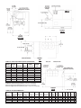
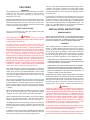
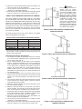
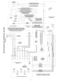
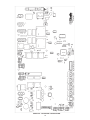
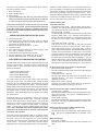
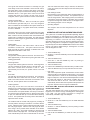
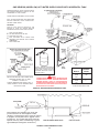
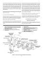
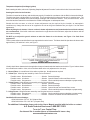
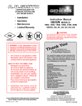
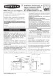
FIGURE 2.
FRONT
FIGURE 1.
LEFT SIDE
FIGURE 3.
TOP
TABLE 1A. BASIC GAS AND ELECTRICAL PARAMETERS
MODEL
GB/GW
300
400
500
650
750
300
400
500
650
750
TYPE OF
GAS
Natural
Natural
Natural
Natural
Natural
Propane
Propane
Propane
Propane
Propane
VOLTS/HZ
120/60
120/60
120/60
120/60
120/60
120/60
120/60
120/60
120/60
120/60
MANIFOLD MANIFOLD
PRESS.
PRESS.
AMPS Inches W.C.
kPa
20
3.5
0.87
20
3.5
0.87
20
3.5
0.87
20
3.5
0.87
20
3.5
0.87
20
10.0
2.49
20
10.0
2.49
20
10.0
2.49
20
10.0
2.49
20
10.0
2.49
All Models - Maximum Supply Pressure: 14 In. W. C. (03.49 kPa)
Minimum Supply Pressure Natural Gas: 4.5 In.W. C. ( 01.22 kPa)
Minimum Supply Pressure Propane (LP) Gas: 11.0 In. W. C. ( 02.74 kPa)
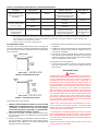
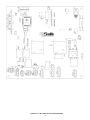
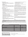
FIGURE 4.
REAR
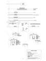
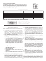
TABLE 1B. ROUGH-IN DIMENSIONS
Model
GB/GW 300
GB/GW 400
GB/GW 500
GB/GW 650
GB/GW 750
Btu/hr.Input
KW Input
Exhaust
Water
Gas
Btu/hr. Input KW Input Propane (LP) Propane (LP) Vent Size Inlet Air Connections Piping Width Width
A
A
B
B
C
C
Natural Gas Natural Gas
Gas
Gas
(Inch)
(Inch) Size (Inch) (Inch) (Inch) (mm) (inch) (mm) (Inch) (mm) (Inch) mm
300,000
88
300,000
88
5
5
1 1/2
3/4 29 1/2 749 14 13/16 376
9
229
12
305
399,900
117
399,900
117
6
6
1 1/2
1
35 3/4 908 17 15/16 456
9
229 14 3/4 375
500,000
147
500,000
147
6
6
2
1
42
1067 21 1/16 535
9
229 14 3/4 375
650,000
190
650,000
190
8
8
2
1 1/4 51 3/8 1305 25 3/4
654
9
229 14 3/4 375
750,000
220
750,000
220
8
8
2
1 1/4 57 5/8 1464 28 7/8
733
9
229 17 1/4 438
2
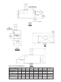
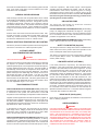
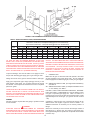
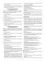
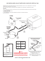
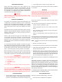
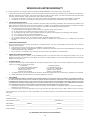
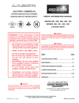
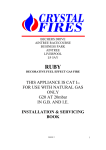
FIGURE 5.
REAR
FIGURE 6.
TOP
FIGURE 7.
LEFT SIDE
FIGURE 8.
FRONT
TABLE 1C. OUTDOOR UNIT DIMENSIONS
MODEL NUMBER
A
B
C
D
E
F
G1
G2
GBO/GWO-300
3
9 3/4
49
13 5/8
34 5/8
67.88
24 3/16
—
GBO/GWO-400
3
9 3/4
55 1/4
13 5/8
34 5/8
68.88
24 3/16
—
GBO/GWO-500
3
9 3/4
61 1/2
13 5/8
34 5/8
68.88
24 3/16
—
GBO/GWO-650
3
9 3/4
70 7/8
13 5/8
34 5/8
68.63
—
27 11/16
GBO/GWO-750
3
9 3/4
77 1/8
13 5/8
34 5/8
68.63
—
27 11/16
3
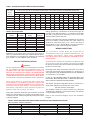
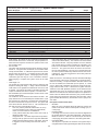
TABLE 2. PUMP PERFORMANCE
Model
GW-300
GW-400
GW-500
GW-650
GW-750
Water
Category
Flow Rate
GPM
LPM
Normal
Hard
Normal
Hard
Normal
Hard
Normal
Hard
Normal
Hard
17
25
23
34
28
42
37
55
42
63
64
95
87
129
106
159
140
208
159
238
Head Loss
Feet
Meter
Rise Temp.
F
C
4.4
9.5
8.0
6.0
4.6
9.1
6.2
12.2
9.7
18.8
30
20
30
20
30
20
30
20
30
20
1.3
2.9
2.4
1.8
1.4
2.8
1.9
3.7
3.0
5.7
2.4
5.3
4.4
3.3
2.6
5.1
3.4
6.8
5.4
10.4
Pipe Size
(Inch)
Pump
Taco Models*
1 1/2"
1 1/2"
1 1/2"
2"
2"
2"
2"
2"
2"
2"
0010
0012
0012
0012
0012
1911 (1/4 HP)
0012
1911 (1/3 HP)
1911 (1/4 HP)
1935 (1/3 HP)
Pressure drop includes the loss through 50' (15.2M) of pipe and normal fittings, when installed with storage
tank.
WATER CATEGORY
NORMAL
HARD
GRAIN HARDNESS PER GAL.
1 THROUGH 15
OVER 15
* Taco Pumps shown. Equivalent Armstrong, Bell & Gossett or Grundfos are acceptable as long as the
flow rates are maintained. Always ensure adequate support for pump and piping.
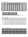
TABLE 3. RECOVERY CAPACITIES
TABLE 4. HEAT EXCHANGER PRESSURE DROP
20 (oF) Rise
Model
PD-Ft.
GB Flow GPM Head
300
25
1.3
400
34
2.2
500
42
3.4
650
55
3.5
750
63
8.3
30 (oF) Rise
PD-Ft.
Flow GPM
Head
17
0.6
23
0.9
28
1.8
37
2.0
42
4.3
TEMPERATURE RISEAND PRESSURE DROP
40 (oF) Rise
10 (oC) Rise
15 (oC) Rise
20 (oC) Rise
PD-Ft.
PD-Meters
PD-Meters
PD-Meters
Flow GPM Head Flow LPM
Head
Flow LPM
Head
Flow LPM
Head
13
0.4
95
0.38
64
0.19
49
0.12
17
0.6
129
0.67
87
0.28
64
0.20
21
0.9
159
1.03
106
0.54
79
0.29
27
1.8
208
1.07
140
0.61
102
0.56
32
2.1
238
2.53
159
1.31
121
0.64
4
FOREWORD
CAUTION
Label all wires prior to disconnection when servicing controls.
Wiring errors can cause improper and dangerous operation of
the boiler.
CAUTION
TEXT PRINTED OR OUTLINED IN RED CONTAINS
INFORMATION RELATIVE TO YOUR SAFETY. PLEASE READ
COMPLETELY BEFORE USING APPLIANCE.
"Verify proper operation after servicing."
Detailed installation diagrams are in this manual. These
diagrams will provide the installer with a reference of materials
needed and a suggested method of piping. IT IS NECESSARY
THAT ALL WATER AND GAS PIPING, AND THE ELECTRICAL
WIRING BE INSTALLED AND CONNECTED AS SHOWN IN THE
DIAGRAMS.
INSTALLATION CLEARANCES
Sufficient area should be provided at the front (2 feet minimum)
and at the water connection side (1 foot minimum) of the unit
for proper servicing. Sufficient clearance should be provided at
the return header side of the boiler to permit access to heat
exchanger tubes for cleaning. In a utility room installation, the
door shall be wide enough to allow the boiler to enter or to
permit the replacement of another appliance.
CHECK THE DIAGRAMS THOROUGHLY BEFORE STARTING
INSTALLATION TO AVOID POSSIBLE ERRORS AND TO MINIMIZE
TIME AND MATERIALS COST. SEE FIGURES 1 THROUGH 4
AND TABLES 1A, 1B AND 1C.
These boilers are approved for installation on noncombustible
flooring in an alcove with minimum clearance to combustibles of:
This design complies with the current edition of ANSI Z21.13 CSA 4.9 for Gas-Fired Low-Pressure Steam and Hot Water
Boilers.
3 inches sides, and back; 3 inches top, front alcove, 6 inches
vent.
MAKE SURE THE GAS ON WHICH THE BOILER WILL OPERATE
IS THE SAME AS THAT SPECIFIED ON THE BOILER RATING
PLATE.
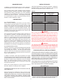
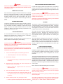
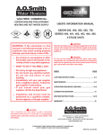
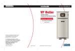
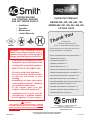
For installation on combustible flooring use the Combustible
Floor Kit. The combustible floor kit base adds 4" to the overall
height of the boiler, see Figure 9.
The boiler installation must conform to these instructions and
the requirements of the local authority having jurisdiction.
In the absence of local code requirements, the installation must
conform to the National Fuel Gas Code, ANSI Z223.1 or CAN/
CSA-B149.1-00 (current edition).
These manuals can be purchased from the Canadian
Standards Association, 8501 East Pleasant Valley Road,
Cleveland, OH 44131
.
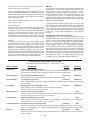
FIGURE 9. BOILER ON COMBUSTIBLE FLOOR BASE
REPLACEMENT PARTS
Model
(GB/GW)-300
(GB/GW)-400
(GB/GW)-500
(GB/GW)-650
(GB/GW)-750
Replacement parts may be ordered through A. O. Smith dealers,
authorized servicers or distributors. Refer to the Yellow Pages
for where to call or contact (in United States) the A. O. Smith
Water Products Company, 500 Tennessee Waltz Parkway,
Ashland City, TN 37015, 1-800-433-2545 or (in Canada) A. O.
Smith Enterprises Ltd., 768 Erie Street, Stratford, Ontario, Canada
N5A 6T3, 800-265-8520. When ordering parts be sure to state
the quantity, part number and description of the item including
the complete model and serial number as it appears on the
product. Refer to the parts lists for more information.
Combustible Floor Kit
210202-001
210202-002
210202-003
210202-004
210202-005
Two inch clearance is required from combustible construction to
hot water pipes.
LEVELLING
Each unit must be checked after installation to be certain that it
is level.
For Technical Assistance call A. O. Smith Technical Information
Center at 1-800-527-1953.
CONDENSATION WARNING
WARNING
THE WATER MANIFOLD IS NOT DESIGNED TO SUPPORT THE
WEIGHT OF THE WATER PIPING SYSTEM. AS ON ALL BOILER
INSTALLATIONS, SPECIAL CARE MUST BE TAKEN TO ENSURE
PROPER SUPPORT.
Your boiler is not designed to operate with a boiler inlet water
temperature of less than 120°F (38°C). Colder inlet water
temperatures will result in significant condensation developing
on the heat exchanger. This situation can cause a corrosive
environment for the heat exchanger, burners and venting resulting
in premature damage, which could result in serious personal
injury or death. Damage caused by excessive condensation will
not be covered under the limited warranty.
WARNING
UNDER NO CIRCUMSTANCES SHOULD THE EQUIPMENT
ROOM WHERE THE BOILER IS INSTALLED EVER BE UNDER
NEGATIVE PRESSURE. PARTICULAR CARE MUST BE TAKEN
WHEN EXHAUST FANS, COMPRESSORS, AIR HANDLING
EQUIPMENT, ETC., MAY INTERFERE WITH THE COMBUSTION
AND VENTILATION AIR SUPPLIES OF THIS BOILER.
For systems that use large volumes of cold water or systems
utilizing heavy water draws, condensation can be prevented by
using a bypass loop.
5
FEATURES
The T & P relief valve should have a temperature rating of 210°F,
a pressure rating NOT exceeding the lowest rated working
pressure of any system component, and a discharge capacity
exceeding the total input of the water boilers supplying water to
the storage tank.
IMPORTANT
Only qualified personnel shall perform the initial firing of the heater.
At this time the user should not hesitate to ask the start-up
technician any questions regarding the operation and
maintenance of the unit.
Locate the T & P relief valve (a) in the top of the tank, or (b) in the
side of the tank on a center line within the upper six (6) inches of
the top of the tank, see Figure 20 and 22. The tapping shall be
threaded in accordance with the latest edition of the Standard for
Pipe Threads, General Purpose (inch), ANSI/ASME B1.20.1. The
location of, or intended location for, the T & P relief valve shall be
readily accessible for servicing or replacement.
Lighting and Operating instructions are included with this manual.
By using these instructions, the user may be able to make minor
operational adjustments and save unnecessary service calls.
However, the user should not attempt repairs, but should contact
a service technician or gas supplier.
SAFETY RELIEF VALVES
INSTALLATION INSTRUCTIONS
Your local code authority may have other specific relief valve
requirements not covered below.
REQUIRED ABILITY
WARNING
THE PURPOSE OF A SAFETY RELIEF VALVE IS TO AVOID
EXCESSIVE PRESSURE WHICH MAY CAUSE TANK EXPLOSION,
SYSTEM OR BOILER DAMAGE.
INSTALLATION OR SERVICE OF THIS BOILER REQUIRES
ABILITY EQUIVALENT TO THAT OF A LICENSED TRADESMAN
IN THE FIELD INVOLVED. PLUMBING, AIR SUPPLY, VENTING,
GAS SUPPLY AND ELECTRICAL WORK ARE REQUIRED.
TO AVOID WATER DAMAGE A DRAIN LINE MUST BE
CONNECTED TO A SAFETY RELIEF VALVE TO DIRECT
DISCHARGE TO A SAFE LOCATION. A DRAIN LINE MUST NOT
BE REDUCED FROM THE SIZE OF THE VALVE OUTLET AND IT
MUST NOT CONTAIN ANY VALVES BETWEEN THE BOILER AND
THE RELIEF VALVE OR THE RELIEF VALVE AND THE DRAIN
EXIT. IN ADDITION, THERE SHOULD NOT BE ANY
RESTRICTIONS IN A DRAIN LINE NOR SHOULD IT BE ROUTED
THROUGH AREAS WHERE FREEZING CONDITIONS MIGHT
OCCUR. DO NOT THREAD OR CAP THE DRAIN LINE EXIT.
RESTRICTING OR BLOCKING A DRAIN LINE WILL DEFEAT THE
PURPOSE OF THE RELIEF VALVE AND MAY CREATE AN UNSAFE
CONDITION. INSTALL A DRAIN LINE WITH A DOWNWARD
SLOPE SUCH THAT IT NATURALLY DRAINS ITSELF.
LOCATION
When installing the boiler, consideration must be given to proper
location. Location selected should be as close to the stack or
chimney as practical with adequate air supply and as centralized
with the piping system as possible. This location should also
be such that the gas ignition system components are protected
from water (dripping, spraying, etc.) during appliance operation
and service [circulator replacement, control replacement, etc.].
• THE BOILER MUST NOT BE INSTALLED ON CARPETING.
• THE BOILER SHOULD NOT BE LOCATED IN AN AREA WHERE
IT WILL BE SUBJECT TO FREEZING.
• THE BOILER SHOULD BE LOCATED NEAR A FLOOR DRAIN.
• THE BOILER SHOULD BE LOCATED IN AN AREA WHERE
LEAKAGE FROM THE BOILER OR CONNECTIONS WILL NOT
RESULT IN DAMAGE TO THE ADJACENT AREA OR TO
LOWER FLOORS OF THE STRUCTURE.
If any safety relief valve is replaced, the replacement valve must
comply with the latest version of the ASME Boiler and Pressure
Vessel Code, Section IV (HEATING BOILERS). Select a relief
valve with a discharge rating NOT less than the boiler input, and
a set pressure NOT exceeding the working pressure of any
component in the system.
WHEN SUCH LOCATIONS CANNOT BE AVOIDED, A SUITABLE
DRAIN PAN SHOULD BE INSTALLED UNDER THE BOILER.
Such pans should be fabricated with sides at least 2-1/2" deep,
with length and width at least 2" greater than the dimensions of
the boiler plus piping connections and must be piped to an
adequate drain. The pan must not restrict combustion air flow.
The storage tank temperature and pressure relief valve must
comply with the applicable construction provisions of the Standard
for Relief Valves for Hot Water Supply Systems, ANSI Z21.22 CSA 4.4 (current edition). The valve must be of the automatic
reset type and not embody a single-use type fusible plug, cartridge
or linkage.
WARNING
THERE IS A RISK IN USING FUEL BURNING APPLIANCES IN
ROOMS OR AREAS WHERE GASOLINE, OTHER FLAMMABLE
LIQUIDS OR ENGINE DRIVEN EQUIPMENT OR VEHICLES ARE
STORED, OPERATED OR REPAIRED. FLAMMABLE VAPORS
ARE HEAVY AND TRAVEL ALONG THE FLOOR AND MAY BE
IGNITED BY THE IGNITER OR MAIN BURNER FLAMES CAUSING
FIRE OR EXPLOSION. SOME LOCAL CODES PERMIT
OPERATION OF GAS APPLIANCES IF INSTALLED 18 INCHES
OR MORE ABOVE THE FLOOR. THIS MAY REDUCE THE RISK
IF LOCATION IN SUCH AN AREA CANNOT BE AVOIDED.
FOR HOT WATER HEATING SYSTEMS, the boilers are shipped
with a 50 psi pressure relief valve. This relief valve is factory
installed in the water outlet header of the boiler, see Figure 1.
FOR HOT WATER SUPPLY SYSTEMS, the boilers are shipped
with a 125 psi pressure relief valve. This relief valve is factory
installed in the water outlet header of the boiler, see Figure 1.
This ASME-rated valve has a discharge capacity that exceeds the
maximum boiler input rating and a pressure rating that does not
exceed the maximum working pressure shown on the boiler
rating plate.
FLAMMABLE ITEMS, PRESSURIZED CONTAINERS OR ANY
OTHER POTENTIAL FIRE HAZARDOUS ARTICLES MUST NEVER
BE PLACED ON OR ADJACENT TO THE BOILER.
In addition, a CSA design-certified and ASME-rated temperature
and pressure (T & P) relief valve must be installed on each and
every water storage tank in the hot water supply system.
OPEN CONTAINERS OF FLAMMABLE MATERIAL SHOULD NOT
BE STORED OR USED IN THE SAME ROOM WITH THE BOILER.
6
If the boiler is installed above the level of heating system terminal
units, a low water cutoff device must be installed in the boiler
outlet at the time of installation.
continuous operation). GB models require a field supplied
operating control be installed in the system. Such as: loop stat,
indoor/outdoor reset control, sequencing panel, or energy
management system. These types of controls connect to the
thermostat wires in the junction box on the boiler. Do not operate
this boiler using the internal high limits only, you must use an
operating stat as mentioned above.
CHEMICAL VAPOR CORROSION
Heat exchanger corrosion and component failure can be caused
by the heating and breakdown of airborne chemical vapors. Spray
can propellants, cleaning solvents, refrigerator and air
conditioning refrigerants, swimming pool chemicals, calcium
and sodium chloride, waxes, and process chemicals are typical
compounds which are corrosive. These materials are corrosive
at very low concentration levels with little or no odor to reveal their
presence.
CIRCULATING PUMP
The pump flow rate should not exceed the maximum
recommended flow rate, see Table 2.
FOR HOT WATER SUPPLY SYSTEMS (GW models), the circulating
pump is an integral part of the Boiler, see Figure 3. This pump
has been lubricated at the factory, and future lubrication should
be in accordance with the motor manufacturer's instructions
provided as supplement to this manual.
Products of this sort should not be stored near the boiler. Also,
air which is brought in contact with the water boiler should not
contain any of these chemicals. If necessary, uncontaminated
air should be obtained from remote or outside sources.
FOR HOT WATER HEATING SYSTEMS (GB models), the circulating
pump is NOT provided and must be field-installed.
MANUAL RESET HIGH TEMPERATURE LIMIT CONTROL
SAFETY FLOW SWITCH (Supplied)
This device prevents the water temperature from reaching 250°F.
This device is located in the outlet temperature probe.
The safety flow switch is a safety device which is installed at the
water outlet of the unit to prevent main burner operation in the
event of inadequate water flow through the boiler.
AUTOMATIC RESET
HIGH TEMPERATURE LIMIT CONTROL
This switch is connected to the CCB, and its status is displayed
on the "System Status" screen. An asterisk indicates switch
closure (water flowing).
CAUTION
LIMIT CONTROLS ARE NOT TO BE USED AS A THERMOSTAT.
LOW WATER CUTOFF (OPTIONAL)
This device prevents the outlet water temperature from reaching
the setpoint. Its operation is based on the feedback from the
outlet temperature probe. If the temperature exceeds the setpoint,
a fault is declared and the gas is shut off. The fault condition is
automatically cleared when the temperature drops below the
high limit setpoint minus the high limit differential. The factory
preset values (and the default high limit values) are 210°F for
GW models and 230°F for GB models. The user can adjust
these values between 90°F and 210°F for the GW models and
90°F and 235°F for the GB models. The factory preset value (and
the default high limit differential value) for both models is 20°F.
The user adjustable range is 1°F to 50°F.
If low water protection is required by the authorities having
jurisdiction, a low water cutoff switch should be installed next to
the boiler in the outlet water line as shown in Figure 23. To meet
code requirements the power connections for this switch can be
connected to the LWCO connections on the CCB, but the
independent contacts for feedback should not be. They should
be connected in series with the ECO. When connected in this
manner, the LWCO dipswitch on the CCB should be off. The
system will not recognize a low water fault condition as a LWCO
fault. It will respond with an ECO fault. The switch should receive
periodic (every six months) inspection to assure proper operation.
A low water cutoff device of the float type should be flushed every
six months. If a LWCO is desired, but not required by code, it can
be connected to the LWCO connections on the CCB and the
dipswitch should be turned to on. The system will then recognize
a low water fault condition as LWCO fault.
TANK PROBE/INLET PROBE
FOR HOT WATER SUPPLY SYSTEMS (GW models), A tank probe
is supplied with each hot water supply boiler. When a tank probe
is connected to the system, the tank section on the UIM
temperature screen will display a temperature instead of dashes.
DRAIN VALVE (Not Supplied)
Drain valves must be obtained and installed on each boiler and
tank for draining purposes.
"Pigtails" of field-supplied wires should be spliced to "pigtails" of
tank probe and to "pigtails" at the junction box. See Figure 21 for
the tank probe installation. Operating control of the system will
be transferred to the tank probe when "Tank Cont" is selected on
dip switch #3 off "SW1" on the CCB.
AIR REQUIREMENTS
WARNING
FOR SAFE OPERATION, AN AMPLE SUPPLY OF AIR MUST BE
PROVIDED FOR PROPER COMBUSTION AND VENTILATION IN
ACCORDANCE WITH THE NATIONAL FUEL GAS CODE, ANSI
Z223.1 OR CAN/CSA-B149.1 (CURRENT EDITIONS) OR
APPLICABLE PROVISIONS OF THE LOCAL BUILDING CODES.
AN INSUFFICIENT SUPPLY OF AIR MAY RESULT IN A YELLOW,
LUMINOUS BURNER FLAME, CARBONING OR SOOTING OF
THE FINNED HEAT EXCHANGER, OR CREATE A RISK OF
ASPHYXIATION. DO NOT OBSTRUCT THE FLOW OF
COMBUSTION AND VENTILATION AIR.
In the absence of tank probe, the inlet probe can be used for
boiler stage control. Staging control will be transferred to inlet
probe when "Inlet" is selected on dip switch #3 on CCB. Make
sure to set the boiler pump for continuous operation.
FOR HOT WATER HEATING SYSTEMS (GB models) Due to the
various types of systems and operating conditions, no factory
operating control is supplied with the GB models. If no probe is
attached to the system, then the dip switch on the CCB should
be set to inlet control (and make sure that boiler pump is set for
7
UNCONFINED SPACE
VENTING THE BOILER
!
This boiler is approved to be vented as a Category I, Category III
(horizontal venting), or a Direct Vent appliance. The Horizontal
and Direct Venting options require a special vent kit.
In buildings of conventional frame, brick or stone construction,
unconfined spaces may provide adequate air for combustion.
If the unconfined space is within a building of tight construction
(buildings using the following construction: weather stripping,
heavy insulation, caulking, vapor barrier, etc.), air for combustion,
ventilation, must be obtained from outdoors or spaces freely
communicating with the outdoors. The installation instructions
for confined spaces in tightly constructed buildings must be
followed to ensure adequate air supply.
TABLE 5.
CONFINED SPACE
(a) U. S. INSTALLATIONS
When drawing combustion and dilution air from inside a
conventionally constructed building to a confined space, such a
space shall be provided with two permanent openings, ONE
WITHIN 12 INCHES OF THE ENCLOSURE TOP AND ONE
WITHIN 12 INCHES OF THE ENCLOSURE BOTTOM. Each
opening shall have a free area of at least one square inch per
1000 Btuh of the total input of all appliances in the enclosure, but
not less than 100 square inches.
Horizontal Vent or
Horizontal Direct Vent Kit
210320-001
210320-002
210320-002
210320-003
210320-003
Model Number
G(W,B) 300
G(W,B) 400
G(W,B) 500
G(W,B) 650
G(W,B) 750
Vertical Direct Vent Kit
210317-001
210317-002
210317-002
210317-003
210317-003
Model Number
G(W,B) 300
G(W,B) 400
G(W,B) 500
G(W,B) 650
G(W,B) 750
CAUTION
When venting the Genesis Boiler through oversize chimney
(including masonry chimneys), additional care must be
exercised to assure proper draft. For proper operation, a
minimum draft of -0.02" w.c. and a maximum draft of -0.04" w.c.
must be maintained. In instances of excessive draft, a barometric
damper may be required to assist in maintaining the proper
draft. Draft should be measured 2 feet above the boiler vent
collar. The vent system must not have external runs greater
than that allowed by local codes or the National Fuel Gas Code.
If the confined space is within a building of tight construction, air
for combustion, ventilation, and draft hood dilution must be
obtained from outdoors. When directly communicating with the
outdoors or communicating with the outdoors through vertical
ducts, two permanent openings, located in the above manner,
shall be provided. Each opening shall have a free area of not
less than one square inch per 4000 Btuh of the total input of all
appliances in the enclosure. If horizontal ducts are used, each
opening shall have a free area of not less than one square inch
per 2000 Btuh of the total input of all appliances in the enclosure.
WARNING
THE INSTRUCTIONS IN THIS SECTION ON VENTING THE
BOILER MUST BE FOLLOWED TO AVOID CHOKED COMBUSTION
OR RECIRCULATION OF FLUE GASES. SUCH CONDITIONS
CAUSE SOOTING OR RISKS OF FIRE AND ASPHYXIATION.
(b) CANADIAN INSTALLATIONS
Ventilation of the space occupied by the boiler(s) shall be provided
by an opening for ventilation air at the highest practical point
communicating with outdoors. The total cross-sectional area
shall be at least 10% of the area of the combustion air opening
but in no case shall the cross-sectional area be less than 10
square inches (6500 mm2).
STANDARD (VERTICAL) VENTING, CATEGORY I
THIS BOILER MAY BE VENTED ACCORDING TO TABLE 5AAND 5C
(ALSO SEE FIGURE 6). AT LEAST TYPE B VENTING MUST BE USED
WITH THE STANDARD VENTING OPTION (thru-the-roof) USING THE
NATIONAL FUEL GAS CODE VENT TABLES.* TYPE B VENT PIPE
CANNOT BE USED IF THE BOILER IS VENTED HORIZONTALLY
(SEE PAGES 10 AND 11). ALL LOCAL UTILITY, STATE/PROVINCIAL,
REGULATIONS ON VENTING MUST BE FOLLOWED.
In addition to the above, there shall be permanent air supply
opening(s) having a cross-sectional area of not less than 1 square
inch per 7,000 BTUH (310 mm2/KW) up to and including 1,000,000
BTUH plus 1 square inch per 14,000 BTU in excess of 1,000,000
BTUH. This opening(s) shall be located at, or ducted to, a point
neither more than 18" (450 mm) nor less than 6 inches (150
mm) above the floor level.
VENT SIZING, INSTALLATION AND TERMINATION SHALL BE IN
ACCORDANCE WITH THE NATIONAL FUEL GAS CODE, ANSI
Z223.1 OR CAN/CSA-B149.1 (CURRENT EDITIONS).
Where power vented equipment is used in the same room as
the boiler, sufficient air openings must be supplied.
VENT CONNECTION
Model Number
Vent Connector
G(W,B) 300
5"
G(W,B) 400
6"
G(W,B) 500
6"
G(W,B) 650
8"
G(W,B) 750
8"
UNDERSIZED OPENINGS MAY RESULT IN INSUFFICIENT AIR
FOR COMBUSTION.
Where an exhaust fan is installed in the same room with a boiler,
sufficient openings for air must be provided in the walls.
UNDERSIZED OPENINGS WILL CAUSE AIR TO BE DRAWN INTO
THE ROOM THROUGH THE CHIMNEY, CAUSING POOR
COMBUSTION. SOOTING MAY RESULT WITH AN INCREASED
RISK OF ASPHYXIATION.
* For vent arrangements other than Table 5A and for proper boiler
operation, a barometric damper is required to maintain draft between
-0.02" w.c. and -0.04" w.c at 2 feet above the boiler vent collar.
8
All boiler venting systems shall be installed in accordance with the
National Fuel Gas Code, ANSI Z223.1 or CAN/CSA-B149.1 (current
edition), or applicable provisions of the local building codes.
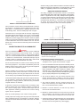
SINGLE PIPE HORIZONTAL VENTING
Vent sizing, installation and termination shall be in accordance
with the NATIONAL FUEL GAS CODE, ANSI Z223.1 OR CAN/CSAB149.1. If applicable, all local, utility, state/provincial regulations
on venting must be followed. This boiler may be vented according
to Table 5A and 5C. The exhaust vent pipe must be "Saf-T-Vent"
manufactured by Heat-Fab Inc. The exhaust vent material type is
AL 29-4C. This vent system must be 100% sealed with a
condensate trap located as close to the boiler as possible.
FIGURE 10. SINGLE PIPE VERTICAL TERMINATION
Vent connections must be made to an adequate stack or chimney
and shall be in accordance with the National Fuel Gas Code,
ANSI Z223.1 or CAN/CSA-B149.1 applicable provisions of the
local building codes. Size and install proper size vent pipe.
Horizontal runs of vent pipe shall be securely supported by
adequately placed (approximately every 4 feet), noncombustible
hangers suitable for the weight and design of the materials
employed to prevent sagging and to maintain a minimum upward
slope of 1/4" per foot from the boiler to the vent terminals. Dampers
or other obstructions must not be installed in the vent. Be sure
that the vent connector does not extend beyond the inside wall of
the chimney.
FIGURE 11. SINGLE PIPE HORIZONTAL TERMINATION
TABLE 5A. SINGLE PIPE HORIZONTAL AND VERTICAL VENTING
CONNECTING BOILER TO A COMMON VENT
CAUTION
When the GENESIS boilers are commonly vented, additional
care must be exercised to assure proper draft. For proper
operation, a minimum draft of -0.02" w.c. and a maximum draft of
-0.04" w.c. must be maintained AT EACH INDIVIDUAL BOILER.
In instances of excessive draft, a barometric damper may be
required to assist in maintaining the proper draft. Draft should
be measured 2 feet above EACH boiler vent collar.
MODEL
EXHAUST VENT*
GB/GW-300
GB/GW-400
GB/GW-500
GB/GW-650
GB/GW-750
110'
50'
50'
50'
50'
* When sizing exhaust piping and intake air piping, 90-degree elbows
are equivalent to 5 feet of straight pipe and 45-degree elbows are
equal to 3 feet of straight pipe.
Intake/Exhaust Installation Requirements:
1. The termination must be a minimum of 12 inches above
anticipated snow or grade level whichever is higher.
Do not connect the boiler to a common vent or chimney with solid
fuel burning equipment. This practice is prohibited by most local
building codes as is the practice of venting gas fired equipment
to the duct work of ventilation systems.
2. Due to normal formation of water vapor in the combustion process,
horizontal terminations must not be located over areas of
pedestrian or vehicular traffic, (e.g., public walkways or over areas
where condensate could create a nuisance or hazard. This is
especially true in colder climates where ice buildup is likely to
occur. A.O. Smith Corporation will not be held liable for any personal
injury or property damage due to any dislodging of ice.
Where a separate vent connection is not available and the vent
pipe from the boiler must be connected to a common vent with
an oil burning furnace, the vent pipe should enter the common
vent or chimney at a point ABOVE the flue pipe from the oil furnace.
3. The minimum distance from the exhaust terminal to any
window, gravity air inlet to a building, or from gas or electric
meter(s) is 6 feet horizontally, 4 feet below and 2 feet above.
UL/ULC listed double wall type B-1 gas vents, through 8" diameter,
can be installed in heated and unheated areas and can pass
through floors, ceilings, partitions, walls and roofs, provided the
required clearance is observed.
4. The minimum distance from the exhaust terminal to an
inside corner formed by two exterior walls is 6 feet but 10
feet is recommended where possible.
At the time of removal of an existing boiler, the following steps
shall be followed with each appliance remaining connected to
the common venting system. Perform these steps while the
other appliances remaining connected to the common venting
system are not in operation.
5. Maintain a minimum distance of 4 feet from any soffit or
eave vent to the exhaust terminal.
Seal any unused openings in the common venting system.
6. Maintain a minimum distance of 10 feet from any forced air
inlet to a building. Any fresh air or make up air inlet such as
a dryer or furnace area is considered to be a forced air inlet.
Visually inspect the venting system for proper size and horizontal
pitch and determine there is not blockage or restriction, leakage,
corrosion and other deficiencies which could cause an unsafe
condition.
7. Avoid areas where condensate drainage may cause problems
such as above planters, patios, or adjacent to windows where
the steam from the flue gases may cause fogging.
9
8. Select the point of wall penetration where the minimum 1/4"
per foot of slope up can be maintained.
9. The through the wall termination kit is suitable for zero
clearance to combustible materials.
10.The mid point of the exhaust and intake air termination elbows
must be a minimum of 12 inches from the exterior wall.
CAUTION
Direct venting into dead air
spaces such as alleys,
atriums and inside corners
can cause recirculation of flue
gases. Recirculation of flue
gases will cause sooting,
premature failure of the heat
exchanger and icing of the
combustion air intake during
severe cold weather.
To
prevent the recirculation of
flue gases, maintain as much
distance as possible between
the combustion air intake and
the exhaust vent terminal.
DIRECT VENT HORIZONTAL AND VERTICAL VENTING
Vent sizing, installation and termination shall be in accordance
with the NATIONAL FUEL GAS CODE, ANSI Z223.1 OR CAN/
CSA-B149.1 (CURRENT EDITIONS). If applicable, all local, utility,
state/provincial regulations on venting must be followed. This
boiler may be vented according to Table 5B and 5C. The exhaust
vent pipe must be "Saf-T-Vent" manufactured by Heat-Fab Inc.
The exhaust vent material type is AL 29-4C. This vent system
must be 100% sealed with a condensate trap located as close
to the boiler as possible.
FIGURE 12. DIRECT VENT HORIZONTAL TERMINATION AND
MINIMUM CLEARANCES
The intake air piping can be PVC, CPVC, ABS or any suitable
intake air piping that can be sealed.
TABLE 5B. DIRECT VENT HORIZONTAL AND VERTICAL VENTING
MODEL
GB/GW-300
GB/GW-400
GB/GW-500
GB/GW-650
GB/GW-750
INTAKE*
60'
35'
35'
35'
35'
EXHAUST*
60'
35'
35'
35'
35'
* When sizing exhaust piping and intake air piping, 90-degree elbows
are equivalent to 5 feet of straight pipe and 45-degree elbows are
equal to 3 feet of straight pipe.
FIGURE 13. DIRECT VENT HORIZONTAL/VERTICAL TERMINATION
Intake/Exhaust Installation Requirements:
1. The exhaust and intake air termination must be a minimum
of 12 inches above anticipated snow or grade level which
ever is higher, see Figure 14.
2. Due to normal formation of water vapor in the combustion
process, horizontal terminations must not be located over
areas of pedestrian or vehicular traffic, (e.g. public walkways
or over areas where condensate could create a nuisance or
hazard). This is especially true in colder climates where ice
buildup is likely to occur. A.O. Smith Corporation will not be
held liable for any personal injury or property damage due to
any dislodging of ice.
3. The minimum distance from the exhaust terminal to any
window, gravity air inlet to a building, or from gas or electric
meter(s) is 6 feet horizontally, 4 feet below and 2 feet
above.
4. The minimum distance from the exhaust terminal to an inside
corner formed by two exterior walls is 6 feet but 10 feet is
recommended where possible.
5. Maintain a minimum distance of 4 feet from any soffit or eave
vent to the exhaust terminal.
6. Maintain a minimum distance of 10 feet from any forced air
inlet to a building. Any fresh air or make up air inlet such as a
dryer or furnace area is considered to be a forced air inlet.
7. Avoid areas where condensate drainage may cause problems
such as above planters, patios, or adjacent to windows where
the steam from the flue gases may cause fogging.
8. Select the point of wall penetration where the minimum 1/4"
per foot of slope up can be maintained.
9. The through the wall termination kit is suitable for zero
clearance to combustible materials.
10.The mid point of the exhaust and intake air termination elbows
must be a minimum of 12 inches from the exterior wall.
FIGURE 14. DIRECT VENT VERTICAL/HORIZONTAL TERMINATION
FIGURE 15. DIRECT VENT VERTICAL TERMINATION AND
MINIMUM CLEARANCES
10
TABLE 5C. INTAKE/VENTING CONFIGURATIONS, CATEGORIES AND MATERIALS
Source for Combustion
Exhaust Venting
Venting Category
Air Supply
Configuration
Boiler Room Air (Using
combustion air from within
the building.)
Direct Venting (Outside
combustion air thru sealed
pipe to boiler intake.)
Vertical Natural Draft
Category I
Horizontal/Sidewall
Venting
Vertical Direct Venting
Category III
Horizontal Direct
Venting
Category III
Category I
Approved Venting
Material Required
Type B Vent Pipe*
(Requires a single-acting,
listed barometric damper if vent
length exceeds Table 5A.)
AL29-4C Stainless Steel
Vent Pipe**
AL29-4C Stainless Steel
Vent Pipe**
AL29-4C Stainless Steel
Vent Pipe**
Type B Vent Pipe*
(Requires a single-acting,
listed barometric damper if vent
length exceeds Table 5A.)
Combustion Air
Intake Material
None
Required
None
Required
PVC, ABS, CPVC**
PVC, ABS, CPVC**
Ducted Air*** (Using
combustion air from outside
Vertical Natural Draft
Category I
PVC, ABS, CPVC,
the building ducted
Galvanized Metal Duct
to boiler intake.)
Pipe**
NOTES: * A standard list type B vent terminal as supplied by the vent pipe manufacturer may be used.
** Vent cap/vent terminations and combustion air intake terminations must be furnished by the boiler manufacturer in accordance with
CSA requirements. No substitutions; unapproved substitutions may/will result in dangerous conditions, nuisance lockouts during
windy conditions and premature boiler failure.
*** Cannot be used in rooms with negative pressure.
4. Reinstall the jacket top and attach the cover plate (along with
its gasket).
5. CAREFULLY cut the exhaust hole through the exposed fluebox
insulation on the back of the fluebox. Dispose of the cut
round piece of insulation.
6. Place the vent collar in alignment with the newly-cut exhaust
hole and drill screw holes through the fluebox, using the vent
collar as a template. Secure in place (along with its gasket)
with the existing sheet metal screws.
FLUE BOX INSTALLATION
This boiler can be vented and/or bring in fresh air through the
rear of the cabinet with the use of the FLUE BOX and vent adaptor.
Any of the previous venting configurations can be installed with
rear connections.
To change the unit to rear intake air:
1. The vent collar (for intake air) and the cover plate (for intake
air) must be switched. Insure all sheet metal screws are
back in place.
GAS CONNECTIONS
WARNING
THIS BOILER IS NOT INTENDED TO OPERATE AT GAS SUPPLY
PRESSURE OTHER THAN SHOWN ON THE RATING PLATE. A
LOCK-UP OR POSITIVE SHUT-OFF TYPE REGULATOR MUST
BE INSTALLED IN THE GAS SUPPLY LINE. EXPOSURE TO
HIGHER GAS SUPPLY PRESSURE MAY CAUSE DAMAGE TO
GAS VALVES WHICH CAN RESULT IN FIRE OR EXPLOSION. IF
OVERPRESSURE HAS OCCURRED SUCH AS THROUGH
IMPROPER TESTING OF GAS LINES OR EMERGENCY
MALFUNCTION OF THE SUPPLY SYSTEM, THE GAS VALVES
MUST BE CHECKED FOR SAFE OPERATION. MAKE SURE THAT
THE OUTSIDE VENTS ON THE SUPPLY REGULATORS AND
THE SAFETY VENT VALVES ARE PROTECTED AGAINST
BLOCKAGE. THESE ARE PARTS OF THE GAS SUPPLY SYSTEM,
NOT THE BOILER. VENT BLOCKAGE MAY OCCUR DURING
ICE BUILD-UP OR SNOW STORMS.
FIGURE 16. STANDARD INSTALLATION
FIGURE 17. REAR VENT INSTALLATION
To change the unit to rear exhaust:
WHEN LOCAL CODES REQUIRE A MAIN MANUAL SHUT-OFF
VALVE OUTSIDE THE BOILER JACKET, A SUITABLE MAIN
MANUAL SHUT-OFF VALVE MUST BE INSTALLED IN A LOCATION
COMPLYING WITH THOSE CODES.
1. REFER TO THE PSD PARTS LIST, PART NO. 212131-000, AND
ORDER THE "FLUE BOX INSULATION" (211909-007 FOR THE
-300 MODEL; 211909-008 FOR THE 400 & 500 MODEL/
211909-009 FOR THE 650 & 750 MODEL). THIS PART MUST
BE IN HAND BEFORE PROCEEDING TO STEP 2.
2. Remove the vent collar, vent collar gasket, jacket top (from
the top) and remove the cover plate and cover plate gasket
(from the rear).
3. Remove as thoroughly as possible the fluebox insulation on
top of the fluebox. REPLACE this part by applying hightemperature spray adhesive on the newly ordered part and
adhering to the top of the fluebox.
IT IS IMPORTANT TO GUARD AGAINST GAS VALVE FOULING
FROM CONTAMINANTS IN THE GAS WAYS. SUCH FOULING
MAY CAUSE IMPROPER OPERATION, FIRE OR EXPLOSION. IF
COPPER SUPPLY LINES ARE USED THEY MUST BE APPROVED
FOR GAS SERVICE.
BEFORE ATTACHING THE GAS LINE BE SURE THAT ALL GAS
PIPE IS CLEAN ON THE INSIDE.
11
FIGURE 18. VENT TERMINATIONS AND INSTALLATION CLEARANCES
TABLE 6. SINGLE UNIT INSTALLATION, SUGGESTED PIPE SIZE
Maximum Equivalent Pipe Length
Natural Gas 1,000 BTU/FT3 0.60 Specific Gravity @ 0.5 In. W.C. Pressure Drop
Propane Gas 2,500 BTU/FT3 1.53 Specific Gravity @ 0.60 In.W.C. Pressure Drop
BTUH
3/4"
1"
1 1/4"
1 1/2"
2"
Input
N
P
N
P
N
P
N
P
N
P
300,000
15
25
35
85
150
380
360
399,900
15
25
60
100
260
250
500,000
10
15
35
65
150
130
360
500
650,000
10
25
45
100
95
250
340
750,000
20
35
80
75
180
260
600
TO TRAP ANY DIRT OR FOREIGN MATERIAL IN THE GAS
SUPPLY LINE, A DIRT LEG (SOMETIMES CALLED DRIP LEG)
MUST BE INCORPORATED IN THE PIPING. The dirt leg must be
readily accessible and not subject to freezing conditions. INSTALL
IN ACCORDANCE WITH RECOMMENDATIONS OF SERVING
GAS SUPPLIERS. REFER TO NATIONAL FUEL GAS CODE, ANSI
Z223.1 OR CAN/CSA-B149.1 (CURRENT EDITION).
2 1/2"
N
-
P
-
OCCUR. THE AREA MUST BE WELL VENTILATED AND ALL
SOURCES OF IGNITION MUST BE DEACTIVATED OR REMOVED.
BEFORE PLACING THE BOILER IN OPERATION, CHECK FOR
GAS LEAKAGE. Use soap and water solution or other material
acceptable for the purpose in locating gas leaks. DO NOT USE
MATCHES, CANDLES, FLAME OR OTHER SOURCES OF
IGNITION FOR THIS PURPOSE.
To prevent damage, care must be taken not to apply too much
torque when attaching gas supply pipe to gas valve gas inlet.
1.
CORRECT GAS
Make sure the gas on which the boiler will operate is the same
as that specified on the boiler rating plate. Do not install the
boiler if equipped for a different type gas, consult your gas supplier.
Fittings and unions in the gas line must be metal to metal type.
Apply joint compounds (pipe dope) sparingly and only to the
male threads of pipe joints. Do not apply compound to the first
two threads. Use compounds resistant to the action of liquefied
petroleum gases.
2A. SIZING GAS SUPPLY LINE, (for single boiler installations),
see Table 6.
2B. SIZING GAS SUPPLY LINE, (for multiple installations of two
or more boilers), see Table 7.
THE BOILER MUST BE ISOLATED FROM THE GAS SUPPLY
PIPING SYSTEM BY CLOSING ITS MAIN MANUAL GAS
SHUTOFF VALVE DURING ANY PRESSURE TESTING OF THE
GAS SUPPLY PIPING SYSTEM AT TEST PRESSURES EQUAL
TO OR MORE THAN 1/2 PSIG.
Use Table 7, which is taken from ANSI booklet Z223.1, NATIONAL
FUEL GAS CODE, or CAN/CSA-B149.1 (current edition) to size
iron pipe or equivalent gas supply line. Table 7 is based on a
pressure drop of 0.5 inches of water and a specific gravity of 0.60
approximately that of natural gas. (LP gas has an S.G. of about
1.53).
PURGING
Gas line purging is required with new piping or systems in which
air has entered.
Capacities in cubic feet per hour of 0.60 specific gravity gas for
different sizes and lengths of pipe are shown in Table 7. No
additional allowance is necessary for an ordinary number of
fittings.
CAUTION
PURGING SHOULD BE PERFORMED BY PERSONS
EXPERIENCED IN THIS TYPE OF GAS SERVICE TO AVOID RISK
OF FIRE OR EXPLOSION. PURGE DISCHARGE MUST NOT
ENTER CONFINED AREAS OR SPACES WHERE IGNITION CAN
Where it is necessary to use more than the average number of
pipe fittings (e.g., elbows, tees, and valves in gas supply line),
use a pipe size larger than specified to compensate for increased
pressure drop.
12
TABLE 7. SUGGESTED PIPE SIZE FOR MULTIPLE GAS APPLIANCES
Nominal
Iron Pipe
Size in
Inches
1
1 1/4
1 1/2
2
2 1/2
3
4
Maximum Capacity of Pipe in Cubic Feet of Gas per Hour for Gas Pressures
of 14 in. W.C. (0.5 psi) or Less and a Pressure Drop of 0.5 in W.C. based on a 0.60 Specific Gravity Gas
Length of Pipe (Feet)
10
20
30
40
50
60
70
80
90
100
125
150
175
200
680
465
375
320
285
260
240
220
205
195
175
160
145
135
1,400
950
770
660
580
530
490
460
430
400
360
325
300
280
2,100
1,460
1,180
990
900
810
750
690
650
620
550
500
460
430
3,950
2,750
2,200 1,900 1,680 1,520 1,400 1,300 1,220 1,150 1,020
950
850
800
6,300
4,350
3,520 3,000 2,650 2,400 2,250 2,050 1,950 1,850 1,650 1,500 1,370 1,280
11,000 7,700
6,250 5,300 4,750 4,300 3,900 3,700 3,450 3,250 2,950 2,650 2,450 2,280
23,000 15,800 12,800 10,900 9,700 8,800 8,100 7,500 7,200 6,700 6,000 5,500 5,000 4,600
Ratings specified by manufacturers for most boilers apply for
elevations up to 2000 feet (600 m). For elevations above 2000
feet (600 m) ratings must be reduced by a rate of 4% for each
1000 feet (300 m) above sea level.
TABLE 8. MULTIPLIER TABLE
Specific
Gravity
0.55
0.60 (natural)
0.65
0.70
0.75
0.80
0.85
0.90
Multiplier
1.04
1.00
0.96
0.93
0.90
0.87
0.84
0.82
Specific
Gravity
1.00
1.10
1.20
1.30
1.40
1.50 (Propane)
1.60
1.70
Multiplier
0.78
0.74
0.71
0.68
0.66
0.63
0.61
0.59
Example: A Genesis boiler is rated at 750,000 Btu/hr. input at sea
level. At an altitude of 5,000 (1500m), the prejet orifices will
decrease the input rate by 20% (= 4% x 5) to a new rating of
600,000 Btu/hr. (= 80% x 750,000 Btu/hr.) The input reduction is
achieved by the prejet orifices through self-regulation.
WIRING CONNECTIONS
ALL ELECTRICAL WORK MUST BE INSTALLED IN
ACCORDANCE WITH THE CURRENT EDITIONS OF THE
NATIONAL ELECTRICAL CODE NFPA 70/CANADIAN
ELECTRICAL CODE, CSA 22.1 AND MUST CONFORM TO LOCAL
REGULATIONS.
Applications of the gravity factor converts the figures given in
Table 7 to capacities with another gas of different specific gravity.
Such application is accomplished by multiplying the capacities
given in Table 7 by the multipliers shown in Table 8.
HIGH ALTITUDE INSTALLATIONS
AN ELECTRICAL GROUND IS REQUIRED TO REDUCE RISK
OF ELECTRIC SHOCK OR POSSIBLE ELECTROCUTION. Make
the ground connection to the wire provided in the electrical supply
junction box on the boiler.
WARNING
INSTALLATIONS ABOVE 5,000 FEET REQUIRE REPLACEMENT
OF THE BURNER ORIFICES IN ACCORDANCE WITH THE
NATIONAL FUEL GAS CODE (ANSI/NFPA 54). FAILURE TO
REPLACE THE ORIFICES WILL RESULT IN IMPROPER AND
INEFFICIENT OPERATION OF THE APPLIANCE, PRODUCING
CARBON MONOXIDE GAS IN EXCESS OF SAFE LIMITS, WHICH
COULD RESULT IN SERIOUS PERSONAL INJURY OR DEATH.
Grounding and all wiring connected to this boiler must conform
to the local code authority having jurisdiction or, in the absence of
such requirements, with the National Electrical Code, ANSI/NFPA
70 or CSA-C22.1 current edition.
IF ANY OF THE ORIGINAL WIRE, AS SUPPLIED WITH THE
APPLIANCE, MUST BE REPLACED, IT MUST BE REPLACED
WITH TYPE 105°C WIRE OR ITS EQUIVALENT.
These Genesis boilers are equipped with prejet orifices which
are self-regulating. This makes it unnecessary to replace these
prejet orifices for high altitude installations (up to 5,000 feet only.
Consult the factory for higher altitudes). These prejet orifices will
automatically compensate for higher elevations and adjust the
appliance's input rate accordingly, see Table 9.
The Genesis Hot Water Supply Boiler must be connected to a
single phase dedicated and isolated line source that is:
120 volts, 60 Hertz, and 20 Amps.
The feedback contacts for a system controller (e.g. Honeywell
Aquastat) that is attached to the thermostat input, must operate
on the provided 24 VAC power.
Some utility companies derate their gas for altitude. You should
contact your gas supplier for any specific changes which may be
required in your area. Call the local gas utility to verify BTU content
of the gas supplied.
Refer to the Connection Diagram and to the Schematic
Diagram.
TABLE 9: ORIFICE SIZE FOR NATURAL AND PROPANE (LP) GASES (U.S. AND CANADIAN INSTALLATIONS)
(Drill size unless otherwise indicated.)
Model
GB/GW 300
GB/GW 400
GB/GW 500
GB/GW 650
GB/GW 750
Rating Input BTUH
300,000
399,900
500,000
650,000
750,000
Number of Burners
6
8
10
13
15
13
Natural (3X)
0.091"
0.091"
0.091"
0.091"
0.091"
Propane (3X)
0.048"
0.048"
0.048"
0.048"
0.048"
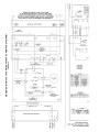
14
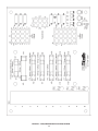
FIGURE 19.
GENESIS GB/GW 300-750 WIRING DIAGRAM
15
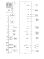
16
FIGURE 20.
GENESIS GB/GW 300-750 SERIES 400-405 SCHEMATIC DIAGRAM
17
FIGURE 21A. - CCB CENTRAL CONTROL BOARD
18
FIGURE 21B. - FCB (FLAME CONTROL BOARD) DIAGRAM
19
FIGURE 21C. - PDB (POWER DISTRIBUTION BOARD) DIAGRAM
20
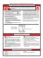
Lighting Instructions for the G(B/W) 300 through 750 models
FOR YOUR SAFETY READ BEFORE OPERATING
WARNING: IF YOU DO NOT FOLLOW THESE INSTRUCTIONS EXACTLY, A FIRE OR
EXPLOSION MAY RESULT CAUSING PROPERTY DAMAGE, PERSONAL INJURY OR
LOSS OF LIFE.
A. THIS APPLIANCE DOES NOT HAVE A PILOT. IT IS
EQUIPPED WITH AN IGNITION DEVICE WHICH
AUTOMATICALLY LIGHTS THE BURNER. DO NOT TRY TO
LIGHT THE BURNER BY HAND.
B. BEFORE OPERATING: SMELL ALL AROUND THE
APPLIANCE AREA FOR GAS. BE SURE TO SMELL NEXT
TO THE FLOOR BECAUSE SOME GAS IS HEAVIER THAN
AIR AND WILL SETTLE ON THE FLOOR.
WHAT TO DO IF YOU SMELL GAS
• DO NOT TRY TO LIGHT ANY APPLIANCE.
• DO NOT TOUCH ANY ELECTRIC SWITCH;
DO NOT USE ANY PHONE IN YOUR BUILDING.
• IMMEDIATELY CALL YOUR GAS SUPPLIER FROM A
NEIGHBOR’S PHONE. FOLLOW THE GAS SUPPLIER’S
INSTRUCTIONS.
• IF YOU CANNOT REACH YOUR GAS SUPPLIER, CALL
THE FIRE DEPARTMENT.
C. USE ONLY YOUR HAND TO OPERATE THE GAS VALVE "ON/
OFF" SWITCH. NEVER USE TOOLS. IF THE SWITCH WILL
NOT OPERATE, DON'T TRY TO REPAIR IT, CALL A
QUALIFIED SERVICE TECHNICIAN. FORCE OR ATTEMPTED
REPAIR MAY RESULT IN A FIRE OR EXPLOSION.
D. DO NOT USE THIS APPLIANCE IF ANY PART HAS BEEN
UNDER WATER. IMMEDIATELY CONTACT A QUALIFIED
INSTALLER OR SERVICE AGENCY TO REPLACE A
FLOODED WATER HEATER. DO NOT ATTEMPT TO REPAIR
THE UNIT! IT MUST BE REPLACED!
E. DO NOT OPERATE APPLIANCE UNLESS UNIT IS FILLED
WITH WATER AND WATER LINES ARE FULLY OPEN.
White Rodgers
Gas Valve 36H
OPERATING INSTRUCTIONS
1.
2.
3.
4.
5.
6.
7.
STOP ! FOLLOW “B” IN THE SAFETY INFORMATION ABOVE ON THIS LABEL. IF YOU DON’T
SMELL GAS, GO TO THE NEXT STEP.
STOP! READ THE SAFETY INFORMATION ABOVE
ON THIS LABEL.
SET THE SYSTEM CONTROLLER TO THE LOWEST
SETTING.
TURN OFF ALL ELECTRIC POWER TO APPLIANCE.
THIS APPLIANCE IS EQUIPPED WITH AN IGNITION
DEVICE WHICH AUTOMATICALLY LIGHTS THE
BURNER. DO NOT TRY TO LIGHT THE BURNER BY
HAND.
REMOVE CONTROL ACCESS PANEL.
TURN ALL GAS VALVES SWITCHES TO "OFF" POSITION, SEE FIGURE ABOVE FOR THE SWITCH POSITION.
WAIT FIVE (5) MINUTES TO CLEAR OUT ANY GAS. THEN
SMELL FOR GAS, INCLUDING NEAR THE FLOOR.
IF YOU SMELL GAS,
8. TURN ALL GAS VALVES SWITCHES TO “ON” POSITION.
9. REPLACE CONTROL ACCESS PANEL.
10. TURN POWER SWITCH TO “ON” POSITION.
11. SET THE SYSTEM CONTROLLER TO DESIRED
SETTING.
12. IF THE APPLIANCE WILL NOT OPERATE, FOLLOW THE
INSTRUCTIONS “TO TURN OFF GAS TO THE
APPLIANCE” AND CALL YOUR SERVICE TECHNICIAN
OR GAS SUPPLIER.
TO TURN OFF GAS TO APPLIANCE
1. SET THE SYSTEM CONTROLLER TO THE LOWEST
SETTING.
2. TURN POWER SWITCH ON APPLIANCE TO “OFF”
POSITION.
3. REMOVE ACCESS PANEL TO EXPOSE GAS
CONTROLS.
4. TURN ALL GAS VALVES SWITCHES TO "OFF"
POSITION.
5. REPLACE CONTROL ACCESS PANEL.
21
There are five (5) electrical connections that must be made for
the boiler to operate correctly.
Should an unsafe condition occur, the control will shut down the
burner and display a red fault light as well as indicate the cause
of the fault on the display. The operating programs for the system
are stored in permanent memory inside the micros. Userselectable operating parameters and a history of detected faults
are stored in re-writable memory in the micros. A loss of power
does not affect either of the memories.
1. Black 120 VAC hot.
2. White 120 VAC neutral.
3. Green ground.
4 (2) [one black/white wire and one yellow/violet wire] 24
VAC thermostat wires [either shorted together or attached
to a thermostat] or (2) [both yellow] tank probe wires.
Inputs to CCB and FCB
Temperature Sensors:
• Temperature probes (CCB - outlet and either inlet or tank is
required): The CCB accepts analog temperature inputs from
up to three sensors (inlet, outlet and tank).
• ECO input (CCB - required):
The ECO (Energy Cut-Off) is a Hi-Limit switch, which is located
inside the outlet probe. It is a normally closed switch that
opens if the probe is exposed to a temperature higher than
the trip point. Once tripped, control system needs manual
reset.
• Thermostat input (CCB - optional):
This input is set up to work with an externally connected
thermostat that provides a contact closure. If this input is
closed and everything else is in the proper state, a "call for
heat" condition will be initiated. These leads should be shorted
together, when a thermostat is not being used. If it is desired
that the thermostat control the temperature of the boiler, the
operating setpoint of the system should be set higher than
the temperature that the thermostat is controlling to. This will
allow the thermostat to control the boiler. When the thermostat
closes, a call for heat will be generated until the thermostat
determines that the required temperature has been reached.
These connections shall be made at the rear of the unit where
a junction box is provided. An electrical ground is required to
reduce the risk of electrical shock or possible electrocution.
A ground wire grounded to the boiler cabinet is provided in the
rear junction box.
CHECK FOR APPROPRIATE ELECTRIC SUPPLY
1. Turn the power OFF.
2. Locate PDB (power distribution board) inside the controls
area. Relocate jumper 'JP1" from "RUN" pins to the "TEST"
pins (These are the left two pins).
3. Disconnect wire harnesses from J1, J2 & J3.
4. Turn power "ON".
5. If the amber and green LED's are lit, electric supply is good.
Go to step 7, otherwise go to step 6.
6. Check polarity and repeat the test until pass.
7. Put the jumper back on the “RUN” pins. Go to step 8.
8. Replace harnesses/jumper to the original position.
ELECTRONIC HOT SURFACE IGNITION CONTROL
The EMC 5000 control system is a fully integrated, state of the art
electronic control system. It consists of sensors, output devices,
a power switch, a 24vac transformer, wiring and the following
printed circuit boards:
•
•
•
•
Air Pressure Sensors (open condition indicates fault):
• Blocked Flue (CCB - required):
Normally closed switch that opens if the flue becomes blocked
during operation.
• Powered Vent (CCB - optional):
Normally open switch that closes when the powered vent is
operating properly. This input is enabled/disabled by a
dipswitch on the CCB.
• Blower Prover (CCB - required).
Normally open switch that closes when the air pressure
produced by the blower is above the set point.
Central Control Board (CCB).
Flame Control Board (FCB).
User Interface Module (UIM).
Power Distribution Board (PDB).
The CCB contains circuitry for both master control and flame
control for the first stage. The FCB contains circuitry for flame
control on up to one additional stage. Dip switches on the CCB
and FCB are used to configure the system. The User Interface
Module (UIM) communicates with the user through a set of touch
pads and a 4-line, 20-character LCD display. The PDB provides
connection points for input power, the water pump, and the
transformer. It also distributes power to the system and contains
the system fuses.
Gas Pressure Sensors (open condition indicates fault):
• Low Gas (CCB - optional):
Normally open switch that closes when the gas pressure rises
above the trip level. This input is enabled/disabled by a
dipswitch on the CCB.
• Hi Gas (FCB - optional):
Normally closed switch that opens if the gas pressure exceeds
a set value. This input is enabled/disabled by a dipswitch on
the CCB and FCB's.
Dual-stage control is accomplished by means of an internal
communications network and the FCB's. One FCB is required
for each stage beyond the initial first stage. The CCB also
contains an external communications system to allow for
connection to a PC, a modem, an EMS system, or something
similar. Through this connection multiple boilers can also be
linked together. CAUTION: The internal communications cables
should never be connected to the external communications
connectors and vice-versa.
Water Level Sensor (open condition indicates fault):
• Low Water Cut Off (CCB - optional):
Normally open switch that closes when water reaches preset
level. This input is enabled-disabled by a dipswitch on the
CCB.
There are several microcontrollers used on the boards. These
micros control the temperature and ignition control functions for
the boiler. Inherent in the design are the normal operating
sequences and safety features associated with a gas ignition
control system. The system continuously performs various
diagnostic tests to verify proper appliance and control operation.
Water Flow Sensor:
• Flow (CCB - required):
Normally open switch that closes when flow exceeds a set
value.
22
IRI Gas Valve Sensor:
• IRI Gas Valve (CCB - optional):
Normally open switch that closes when the IRI Gas Valve is
operating correctly. This input is enabled/disabled by a
dipswitch on the CCB.
• Flame Sensor:
Flame (CCB - required).
Returns a signal to the microprocessor if flame is detected in
the burner. If the probe is missing or shorted, the flame will
not be detected. This input is enabled/disabled by a dipswitch
on the FCB.
•
Provides power to activate the gas valve. The gas valve cannot
be activated when the ECO contacts are open
Direct Connection Output:
Low Water Cut Off (CCB - 24vac - optional)
Directly connected to the 24 vac line to provide power to operate
an external LW/CO device.
CCB/FCB Indicator Lamps & Fuses
A green LED is mounted on the PDB to indicate when line voltage
is applied. (The CCB/FCB/PDB also contain a yellow, green, red
LED, and a test/run jumper, that are used during installation to
verify proper power connections.) A red LED on the CCB is used
to indicate when the 24vac input fuse has blown. The FCB's also
have fuses on their 24vac power line. (Recommended
replacement fuses are: Littlefuse p/n 29707.5 for the 7.5 amp
CCB fuse, and Littlefuse p/n 297003 for the 3 amp FCB fuses.)
Repeated failure of a fuse is an indication of failure in some
part of the system.
Outputs from CCB and FCB's:
Relay Contact Output:
• IRI Gas Valve (CCB - 120 vac - optional):
Provides electrical power to operate an IRI Gas Valve Device.
• Alarm (CCB - 24vac - optional):
Provides electrical power to operate an external alarm. This
can be an audio device (i.e. Sonalert), a visual device (lamp),
or any other device that will operate with the voltage and current
level provided.
• Pump (CCB - 120vac - required on systems that do not have
an external pump):
Provides electrical power to directly operate a pump or the
coil of an externally connected contactor.
• Powered Vent (CCB - 24 vac - optional):
Provides electrical power to operate a powered vent.
• Blower (CCB / FCB - 120vac - required).
Single speed blowers utilize the high blower output only. Dip
switches on the FCB's enable/disable the use of blowers on
stages 2, 3 and 4.
• Igniter (FCB - 120vac - required).
Provides power to operate the HSI igniters. Dip switches on
the FCB's enables/disables the use of HSI igniters on stages
2, 3 and 4.
• Gas Valve (FCB - 24vac - required):
Yellow LED's are located near the micros on the CCB and FCB's.
These LED's are "heartbeat indicators" and blink approximately
twice per second to indicate that the micros are running. (The
blink rate of the LED next to the micro that controls the silicon
Nitride igniter will change when the igniter is being powered and
when a fault is detected with the operation of that igniter.)
CCB/FCB Jumpers:
The CCB has two jumpers and the FCB has one. JP1 on the
CCB is used to terminate the external communications line. It is
normally left off and installed when the external cable is very
long. JP2 on the CCB and JP1 on the FCB, are for factory use
only.
Igniters
The EMC 5000 system operates with Silicon Carbide Igniter.
CCB/FCB Dip Switches:
Dipswitch configurations are READ ONLY ON POWER UP. These switches are only to be set at the factory or by authorized-trained
personnel only! Once set at installation they generally remain that way for the duration of the life of the product. If a switch is changed,
power must be cycled before the change will take effect. The status of all dipswitches can be observed on the system status screen
on the UIM.
CCB - Ten Position Dipswitch (Central Control Board)
SWITCH
Switch 1: Selection of the type of boiler application:
On = GB/LB
Switch 2: Trials for Ignition:
On = 3
Switch 3: IRI Gas Valve Option:
On = IRI
Switch 4: Controlling Probe:
On = Tank
Switch 5: Powered Vent:
On = Yes
Switch 6: Low Water Cut Off:
On = Yes
Switch 7: Low Gas
On = Yes
Switch 8: Spare:
Switch 9 & 10. Number Stages (FCB's):
9
Off
Off
Off
Off
Off
Off
Off
Off
10
On
= GW/LW
=1
= No IRI
= Inlet
= No
= No
= No
#stages
= 2
NOTE: If the unit power up with the number of stages selected by dip switches exceeding the number of FCBs, the CCB will detect
this condition and go into a hard lockout. After changing the dip switches to the correct number of stages, the power must be
cycled off and on to accept the change.
Example of Dip Switch configuration:
GW model, 1 ignition trial, No IRI, Inlet control, No Power Vent, No LWCO,
No Low Gas, 2 stage.
23
CCB - Three position Dipswitch (SW2):
This dipswitch is similar to the FCB dipswitches described below, but with
only three switches being used: the number of blower speeds (switch #3), Hi
Gas option (switch #2) and a spare (switch #1). Only the blower speed selection
and Hi Gas are required because FCB1 always has a blower, igniter, flame
checking, and the address is always stage 1.
CCB-SW2
FCB - Eight position Dipswitch
SWITCH
Switch 1: Spare:
Switch 2: Hi Gas:
Switch 3: Number of Blower Speeds:
Switch 4: Igniter used:
Switch 5*: Blower used:
Switch 6: Flame Checked:
Switch 7 & 8. Stage selection:
On
On
On
On
On
7
On
=
=
=
=
=
Yes
1 speed,
Yes,
Yes,
Yes,
8
Off
Off = No
Off = 2 speed
Off = No
Off = No
Off = No
Stage #
2
*When switch 5 is in off (no blower) position, switch 3 (blower speeds) is ignored.
Example of Dip Switch configuration:
No high gas, 1 blower speed, no igniter,
no blower, no flame check, Stage 2.
Appliance Operating Sequence
4.
NOTE: The following sequence is based on a two-stage system.
1.
2.
3.
The EMC 5000 controller has four modes of operation:
Initialization, Standby, Running, and Service. The internal
CCB and FCB micros control these modes through a
sequence of steps (or States) which are further described
in the "UIM Operating Procedures" section.
When power is applied to the system, it enters the
initialization mode and the following automatic functions
are performed:
• A. O. Smith opening screen is displayed.
• The system goes through a calibration indicated by the
green running LED blinking and then staying on; next
the red service LED and yellow standby LEDs come on,
next the stage 1 service and runnings LEDs blink ON
and OFF followed by stage 2, stage 3, stage 4 and then
back to stage 1, 2, 3, 4 LEDs.
• Stored values are recalled from memory.
• Configuration dipswitches are read.
• Pending faults are recalled
• Micros on all boards start running (indicated by a flashing
Yellow LED near each micro)
• Input sensors are read
• Communications between micros and boards is
established
• FCB's are configurated with the number of ignition trials
to run.
After initialization is complete (approximately 10 seconds)
the system turns the green LED off and goes to the standby
mode (yellow "Standby" LED on), unless a previously stored
fault has been recalled, which will send the system into the
service model (red "Service" LED on). In standby mode
the display shows the temperature screen and in fault mode
5.
6.
7.
8.
9.
10.
11.
12.
13.
the current error screen is displayed.
The system then compares the temperature read from the
controlling probe (inlet or tank) to the setpoint temperature.
If the temperature is less than the operating setpoint minus
the differential temperature and the thermostat input is
closed then a call for heat is established and the system
shifts to the run mode (green "Running" LED turns on).
The heating sequence begins by applying power to the
pump and, if selected, the powered vent and the IRI gas
valve.
After a few seconds the Blower is turned on to perform a
cold purge of the chamber.
The stage 1 igniter is turned on.
After the Silcon Carbide igniter has reached a minimum of
2.8 amps, a current transducer relay is activated and closes
contacts for the safety gas valve circuit. This allows the gas
valve power circuit to become energized.
After 1.5 seconds the system checks the status of the flame
sensor. If flame is detected the system leaves the gas
valve "ON". Note: If the "Ignition Tries" dipswitch is set for 3
tries the system will not declare an error until it tries the
ignition sequence three times. If it is set to 1 try then the
system will declare an error anytime a fault is detected.
The system now activates the other FCB stages depending
upon a control algorithm scheme that is described below.
After 5 seconds the system turns on the gas valve for
stage 2.
Carryover flame from stage 1 ignites stage 2’s burners.
The system is now in the heating mode with both stages
on and will remain in this mode until the call for heat is
satisfied or a fault occurs.
NOTE: In standby and running modes the system constantly
monitors the signals and the internal operation for faults. Any
detected fault will halt the heating sequence and shift the system
to the service mode, where the detected fault will be displayed.
24
UIM Screens:
On all screens a double vertical bar appears on the right side of
the display each time a key is touched to indicate that a key has
been activated. On several screens an indicator ">" appears on
the left side of the display to indicate the active line. The "Up/
Down" keys are used to move the indicator to the desired line
and the "Select" key is pressed to select the line. Also, on most
of the screens, up/down arrows appear on the right side of the
screen to indicate that there is additional lines either above or
below the displayed four lines.
Temperature Setpoints (System Control Algorithm)
The boiler has a hysteresis type control, which means that it will
begin heating the water when the temperature sensed by the
control probe (inlet or tank) falls below the operating setpoint
minus the differential setpoint for stage 1. It will stop heating the
water when the temperature rises to the operating setpoint. If
the system has multiple stages then the differential setpoint for
each stage is also subtracted from the operating setpoint. The
following examples will further explain this operation.
• Menu Screen:
Displayed when the user presses the "Menu" key. This screen
is the selection point for the other 9 screens.
• Temperature Screen:
Displays the sensed temperatures of the Outlet, Inlet, and
Tank probes. Also displayed is the calculated Delta T (Outlet
minus Inlet) for the system. Shorted ("Short") and
disconnected ("----") probes are also displayed.
• System Status Screen:
This screen is used to view the status of switch inputs and
output states. An asterisk (*) is displayed next to the label
when the status is "True" (the description is fulfilled). For
example, if water is flowing, or detected by the flow sensor,
then an "*" will appear in front of the Flow label (i.e. *Flow).
Another example would be the ECO switch. If the outlet
temperature is too high the display will show: *ECO.
Setup: 2 stage system, operating setpoint - 140, stage 1 to 2
differential setpoints = 10.
Example 1. Temperature begins at 150 and drops to 90, see
Figure 18A. At 140 the system remains in idle mode. As the
temp drops to 130 (140-10) stage 1 turns on and stage 2 remains
off. At 120 stage 2 also turns on.
Example 2. Temperature begins at 90 and rises to 150, see
Figure 18B. At 100 both stages are on. (This is the case when a
boiler is first started and the controlling temperature is below the
operating setpoint minus all of the differential setpoints. At that
time both stages are turned on, in sequence from 1 to 2. At 130
stage 2 turns off. At 140 both stages are off.
Stages 1 and 2 will turn on in sequence from 1 to 2.
NOTE: The LWCO, IRI Gas Valve, Powered Vent, High Gas, and
Low Gas inputs are optional inputs. Flame sensing, Igniters,
and Blowers are optional on Stages 2, 3 and 4. (Except on a 4stage system, stage 2 always has an Igniter, Blower, and Flame
Sensor. Those dipswitches on stage 2 are not relevant.) One or
two speed blowers can be used on any stage.
The System monitors the inputs at these times:
FIGURE 22A.
FIGURE 22B.
• ECO, LWCO, Blocked Flue, Low Gas, Hi Limit, and Hi Gas - at
all times for a fault condition.
• Tstat - at all times for open/closed conditions.
• IRI Gas and Powered Vent - for an on condition when their
outputs (Pump, IRI Gas Pwr, Powered Vent Power) are turned
on and an off condition at all other times.
• Flow - for an on condition when the pump is on (no check for
off state)
• Blower Prover - when the Blower is on.
• Igniter Current - for an on condition approximately 18 seconds
after the Igniter is turned on until the igniter is turned off and an
off condition at all other times.
• Flame - for an on condition approximately 5 seconds after the
gas valve is turned on until the valve is turned off and at all
other times for an off condition.
UIM OPERATING PROCEDURES
Control Status Screen:
Displays the status that the CCB and FCB micros are in. The
CCB has 5 possible states and the FCB's have 9. The normal
CCB states sequence is to move from Idle, to Pre-Circulate, then
to Heating Stage 1-2 when a call for heat is initiated. Once heat
has been satisfied or the Thermostat is opened, the sequence
moves to Post-Circulate and then back to Idle. If a fault occurs at
any time, the process jumps out of sequence and goes directly
to the appropriate Hard or Soft Fault state.
FIGURE 23. UIM, USER INTERFACE MODULE
The UIM receives commands from the user and displays
operational information to the user via an LCD (liquid crystal
display) up to eleven LED's, and five touch switches. The LCD
provides information to the user by the use of 10 menu-activated
screens. Within each of the screens, helpful information can be
displayed by pressing the "Help" button. The LED's visually inform
the user about the mode the system is in. The touch switches
allow the user to control the operation of the system. The
operation of these parts is described in the following section:
Description of CCB control states:
• Idle:
The yellow "Standby" LED is turned on and the system waits
for a heat request (determined by the Thermostat or controlling
25
The following status information is displayed from the
Status Displayed
ECO
LW/CO
Blk Flue
Flow
Low Gas
Tstat
Hi Limit
Pump
IRI Gas Pwr
IRI Gas
Pwr Vent
Alarm
Pwr Vent Pwr
BlwHi Prv
Blw Hi
BlwLo Prv
Blw Lo
Ignt Cur
Ignit
Gas Relay
Hi Gas
Flame
•
•
•
System Status Screen:
*(True Condition)
Outlet temperature too high
Water Level low
Flue blocked
Water flowing
Gas pressure low
Thermostat requesting heat
Outlet temp exceeds High Limit setpoint
Pump output activated
IRI output relay activated
IRI Gas Valve on
Power Vent running
Alarm output activated
Power Vent output relay activated
- - - - STAGES 1 to 2 - - - Blower pressure sufficient
Blower High output activated
Blower pressure sufficient (not used at this time)
Blower low output activated (not used at this time)
Igniter current sufficient for ignition
Igniter output is activated
Gas output relay activated
Gas pressure too high
Flame detected
probe inputs). All outputs are off in this state except that if the
Post-Circulate time is set to continuous, the pump will be on.
When the heat request is received, the system moves to the
Pre-Circulate state.
Pre-Circulate:
The yellow LED is turned off and the green "Running" LED is
turned on. The green LED will remain on for all other states
except the fault states. If enabled the powered vent and the
IRI gas valve are turned on. A command is sent to all active
stages to cold purge the system. Cold purging clears out any
combustion gas that may be in the combustion chamber.
When purging is complete the system moves to the Heat
State.
Heat Stages 1-2:
The system will command the FCB micros to start their heat
sequence starting with stage 1. Stage 2 will be activated in
order based on an algorithm that determines how much heat
is needed. The system will remain in this state until the heat
request is satisfied, the Tstat is opened, or a fault occurs.
Soft Fault State: (See "Fault Description" section for list of soft
and Auto Reset faults.)
The CCB turns off the Powered Vent and the IRI Gas. The
pump remains on for the selected post-circulate time to cycle
the hot water out of the boiler. The FCB's are commanded to
shut down and the Alarm output is turned on. The green LED
turns off and the red "Service" turns on. The CCB remains in
this state until one of the following occurs:
•
One hour passes (automatic restart after one hour)
•
If Communications error system will automatically
restart if communications re-establishes.
•
If user presses Select key while current error screen is
displayed (Hard reset).
•
If high-limit error - the outlet temperature drops below
the high limit trip point minus the high limit differential.
(outlet water temperature drops to safe level). The fault
is logged in the error history when the fault state is
exited.
•
Input
Output
open
open
open
closed
open
closed
---------closed
closed
-------
---------------------On
On
------On
On
closed
---closed
------------open
----
---On
---On
---On
On
-------
Hard Fault State: (See "Fault Description" section for list of
soft and Auto Reset faults.) The CCB turns off the Powered
Vent and the IRI Gas. The pump remains on for the selected
post-circulate time to cycle the hot water out of the boiler. The
FCB's are commanded to shut down and the Alarm output is
turned on. The green LED turns off and the red "Service"
turns on and off (flashes). The only way to exit this state is for
the user to press the Select key while the current error screen
is displayed. The fault is logged in the error history when the
fault state is exited.
While the CCB is in the Heating mode the activated FCB stage
moves from Idle, to Pre-Purge, to Heat Igniter, to Check for Flame,
and then to Heating. The process waits in this state until the call
for heat is satisfied, the thermostat input is opened, or a fault
occurs. When heat is satisfied, the sequence continues to PostPurge and then back to Idle. If three tries for ignition has been
selected on the CCB dipswitch and flame is not detected at the
appropriate time, then the sequence moves to the Inter-Purge
state for 15 seconds and the FCB heat sequence is repeated. If
flame is still not detected after the third try the process declares
a fault, jumps out of sequence and goes to the error state. Other
types of faults detected at any time will also cause a jump to the
error state.
Description of FCB control states:
• Idle State:
When any error is declared during idle state-The system will
remain in this state until the CCB request a heating cycle, or
a cold purge.
• Pre-Purge State:
If the stage does not have a blower, this state is skipped and
the system advances to the Heat Igniter State. Otherwise the
Blower is turned on. After 10 to 34 seconds (34 seconds for
cold purging) the system switches to the Heat Igniter State.
• Heat Igniter State:
The sequence of operation is as follows: "The igniter relay is
energized and the heat up period begins. After 18-20 seconds,
26
This time allows the blower relay to activate, the blower to
come up to speed, and the response from the blower prover
to be filtered.
if the igniter has reached a minimum of 2.8 amps, the gas
valve safety circuit is then activated. If in this amount of time,
the igniter fails to reach a minimum amp draw of 2.8 amps,
the unit will re-cycle up to 3 times before locking out on igniter
hardware failure. If the igniter does reach the minimum
required amp draw of 2.8 amps, the gas valve circuit is
energized, and the system advances to Flame Check status.
•
Check for Flame State:
The gas valve is turned on. After 1.5 seconds, the system
checks that the gas valve relay is on. If it is not, the ignition
trial is considered to have failed and the system advances to
the Inter-Purge state, if any ignition trials remain, otherwise
an error is declared.
•
•
1. Touch the MENU key.
2. Scroll the ">" with the DOWN key next to the USER SETTING
SCREEN.
3. Touch the SELECT key.
4. Scroll the ">" with the DOWN key until it is pointing to
OPERATING SETPOINT.
Post-Purge State
The gas valve and the igniter are turned off. If this stage does
not have a blower the system returns to the idle state. If it
does have a blower then the blower is left on. After
approximately 25 seconds, the system returns to the Idle
state.
•
Cold Purge State
Cold purge occurs when the CCB micro commands all
blowers to go on before lighting the first stage to clear the unit
of residual gases. This state normally lasts approximately
32 seconds but on a special situation can last up to 5 minutes.
If on the first call for heat after power up, blower prover switch
is open, this state will take up to 5 minutes before declaring
an error. This special mode is used by service technicians to
adjust the blower shutter.
Operating Setpoint:
The system has a standard programmable Operating Setpoint
range of 70 Degrees F to 190 Degrees F for a GW and of 70
Degrees F to 220 Degrees F for a GB for either tank or inlet probe
depending on selection. The user can easily change the
Operating Setpoint at any time by using the following procedure.
When any configuration or setpoint is changed (and the Select
key touched), the new value is IMMEDIATELY saved to non-volatile
memory. The factory default setting is 145 Degrees F for a GW
and 190 Degrees for a GB.
Inter-Purge State:
The gas valve and the igniter are turned off. The blower is on.
After approximately 15 seconds the system goes back to the
Heating Igniter State.
Error State
The gas valve and the igniter are turned off. The FCB micro
tells the CCB micro which error has occurred. The system
waits in this state until the CCB sends a command to clear
the error, and the system returns to the idle state.
•
OPERATING SETPOINT ADJUSTMENT PROCEDURE
Heating State:
The system remains in this state until the call for heat is
cancelled or a fault occurs. The system returns to the Idle
state if the call for heat is cancelled, or satisfied and to the
appropriate fault state if a fault occur.
•
User Settings Screen:
Each setpoint or user setting has either a limited selection of
values, or a limited range of values. The Up/Down keys are
used to change values. After changing an item, the Select key
is pressed to accept the change, or the Menu key is pressed
to reject the change and restore the item to its original value.
The following setpoints can be changed:
This setpoint sets the base temperature for the control
algorithm.
The flame sensor is checked. If flame is detected, the igniter
is turned off. The state machine then advances to the Heating
State. If after 5 seconds, the flame is still not sensed then the
ignition trial is considered to have failed. The state machine
advances to Inter-Purge if any ignition trials remain, otherwise
an error is declared.
•
•
5. Touch the SELECT key.
6. Use the UP or DOWN key to select the value you wish to enter.
7. Touch the SELECT key to accept and store the new value.
•
High Limit:
The outlet temperature probe contains both an ECO switch
and a thermistor for temperature measurement. The sensed
outlet temperature is used for the automatically resettable
High Limit setpoint. If the sensed outlet temperature exceeds
the High Limit setpoint, a "soft lockout" condition will occur
and the burner will be shut off. This fault condition is
automatically cleared when the temperature drops below the
high limit setpoint minus the high limit differential.
AUTO HIGH LIMIT SETPOINT ADJUSTMENT PROCEDURE/
OUTLET TEMP. PROBE
The High Limit setpoint has a range of 90 Degrees F to 210
Degrees F for a GW and a range of 90 Degrees to 235 Degrees
F for a GB. Use the following procedure to change the
automatically resettable High Limit Setpoint:
1. Touch the MENU key.
2. Scroll the ">" with the DOWN key next to USER SETTING
SCREEN.
The CCB will wait the normal cold purge time (normally 32
seconds) before checking for activation of all active blower
prover. If blower prover is active at this time the CCB cancels
the cold purge request. After the first cold purge has been
done a flag is set to prevent further activation of the shutter
adjust 5 min. delay. Any further requests for cold purge will
last the normal cold purge time. The FCB will go into fault
mode if the blower prover does not activate after 15 seconds.
3. Touch the SELECT key.
4. Scroll the ">" with the DOWN key until it is pointing to HIGH
LIMIT SETPOINT.
5. Touch the SELECT KEY.
6. Use the UP and DOWN key to select the value you wish to
enter.
27
units from trying to respond to the same request from the PC
or supervisory network device.
7. Touch the SELECT key to accept and store the new value.
•
High Limit Differential:
The outlet temperature must be below the automatic High
Limit setpoint minus the High Limit Differential setpoint before
a call for heat can be generated.
•
•
Log & System Info Screen:
Displays the following information:
Elapsed hours of operation (Total time system has been
powered up)
Number of running minutes (Number of minutes system has
been in the run mode)
Number of cycles for each stage (Number of times stage has
been in heat mode).
Kbtu rating of the boiler (0 to 5750Kbtu in 10Kbtu increments)
The software revision level of the CCB, and FCB
microcontrollers.
Current Error Screen:
• Displays the last error that the system has detected plus a
time stamp of when the error occurred. (The time stamp is
based on the elapsed hours value at the time the error
occurred. It is displayed in hours and minutes. This error
remain displayed as long as it is still valid. When cleared it is
moved to the Error History Screen. The system will
automatically jump to this screen when an error is detected.
It will also go to this screen upon power-up if an error was still
valid when power was turned off.
HIGH LIMIT DIFFERENTIAL SETPOINT
ADJUSTMENT PROCEDURE
The High Limit Differential Setpoint has a range of 1 Degree F to
50 Degrees F for all models. Use the following procedure to
change the High Limit Differential Setpoint:
1. Touch the MENU key.
2. Scroll the ">" with the down key next to USER SETTING
SCREEN.
3. Touch the SELECT key.
4. Scroll the ">" with the DOWN key until it is pointing to HIGH
LIMIT DIFFERENTIAL SETPOINT.
5. Touch the SELECT key.
6. Use the UP or DOWN key to select the value you wish to enter.
7. Touch the SELECT key to accept and store the new value.
•
Operating Differential Setpoints:
Each of the two stages has an independent Operating
Differential setpoint.
NOTE: Errors are cleared from this screen by pressing the
"select" key.
OPERATING DIFFERENTIAL SETPOINT
ADJUSTMENT PROCEDURE
Each of the two stages has an independent Operating Differential
Setpoint. The range of these setpoints is from 1 Degree F to 50
Degrees F for all models. Use the following procedure to change
this setpoint:
1. Touch the MENU key.
•
Error History Screen:
This screen displays a list of the last 9 errors (with time
stamps) that have occurred. The last error to occur is displayed
first. If a new error occurs this screen is presented to display
the error.
•
Reload Defaults Screen:
From this screen the user can restore the factory default values
for screen adjustable configurations by pressing the Select
key. The values restored are as follows:
2. Scroll the ">" with the DOWN key next to USER SETTING
SCREEN.
3. Touch the SELECT key.
GW Models
Oper Setpnt (Operating Setpoint) - 145° F (63° C)
Stage1 Diff (Operating Setpoint Differential) = 3° F (2° C)
Stage2 Diff (Operating Setpoint Differential) = 6° F (3° C)
Hi Limit (High LImit Setpoint) = 210° F (99° C)
Hi Limit Dif (High Limit Differential) = 20° F (11° C)
4. Scroll the ">" with the DOWN key until it is pointing to
OPERATING DIFFERENTIAL SETPOINT.
5. Touch the SELECT key.
6. Scroll the ">" with the DOWN key until it is pointing to the
STAGE you want.
7. Touch the SELECT KEY.
GB Models
Oper Setpnt (Operating Setpoint) = 190° F (88° C)
Stage1 Diff (Operating Setpoint Differential) = 3° F (2° C)
Stage2 Diff (Operating Setpoint Differential) = 6° F (3° C)
Hi LImit (High LImit Setpoint) = 230° F (110° C)
Hi Limit Dif (High Limit Differential) = 20° F (11° C)
8. Use the UP and DOWN key to select the value you wish to
enter.
9. Touch the SELECT key to accept and store the new value.
•
Temperature Units:
Temperature can be displayed in either °F or °C units.
•
Post Circulate Delay Time:
The time circulation pump will stay on after the burner is turned
off. The time in seconds is adjustable with the following
values: 45, 90, 180 or continuous. If the continuous value is
selected the pump will remain on at all times and the post
circulate state time will be set at 45 seconds.
•
Configuration Settings Screen:
Displays the status of the dipswitches installed on all boards
as described earlier.
Both Models
Tempert Units (Temperature Units) = F
Post Cir Secs (Post Circulation pump delay = 45 seconds
Network Address (Network Address) = (none)
UIM Touch Switches
Below the LCD display are five touch switches or keys, that the
operator uses to operate the system.
Network Address:
This is a unique number assigned to this boiler to differentiate
it from other boilers or water heater on the same A. O. Smith
proprietary network. A valid Network Address can be any
number from 1 to 31. It is set by default to zero, which is an
invalid address. The boiler will not communicate until it is
changed to a valid and unique number. This prevents two
•
•
28
Menu Key:
Pressing this key activates the menu screen where the other
screens can be accessed.
Select Key:
This key performs several functions. Screens can be selected
UIM LED's
The three LED's to the right of the LCD indicate the status of the
overall system. The red LED indicates that a fault has been
detected and the system has stopped running. It is on
continuously for soft faults and flashes for hard faults. The Yellow
LED indicates that the boiler is in a ready mode waiting for a call
for heat command. When on continuously the Green LED
indicates that the system is in the heating mode. If it is flashing
it indicates that the UIM is in the initialization mode and the touch
switches are being calibrated.
from the menu screen by pressing this key when the">"
appears next to the screen desired.
On the User Settings screen items that appear next to a ">"
symbol can be selected with this key. If a setpoint configuration
item is selected, the ">" will then flash slowly to indicate that
the item has been selected. The Up and Down keys are then
used to change its value.
From the Current Error Screen this key is used to reset the
system from an error:
•
•
On these boilers there are also eight LED's on the lower right
that indicate the state of the individual FCB's. The red LED's are
only on when the main red LED is on and indicate which FCB
has the error. The green LED indicates when flame is proved
on that particular stage, unless the dipswitch for sensing flame
is turned off. Then the LED indicates that the gas valve has
turned on.
Up and Down Keys:
These keys are used to move upwards and downwards in
screens to reach a desired item and to change setpoints and
user settings. They have an auto increment/decrement feature
for some of the configurations and values. When you first
press one of the keys and value changes by 1 count, then
wait 1/2 second and changes slowly until the key is released
or if held for 3 or more seconds it will change the value quickly.
Fault Messages and Troubleshooting Guide
The EMC5000 system does excessive self-diagnostics and
displays detected faults on the UIM display in an easy to read
manner. There are approximately 80 different faults that can be
detected. Some of the faults are caused by internal problems
and some by external causes. The faults create different types of
system lockouts (shut down). Hard lockouts are serious
problems that require the user to manually restart the system.
Soft lockouts can be reset by the user or after 60 minutes the
system will automatically clear the error and restart. Auto Reset
lockouts will monitor the cause of the fault and if the fault clears
itself the system resets itself. The fault is recorded and the system
immediately resets itself. The following table shows the fault
messages and some possible troubleshooting hints:
Help Key:
Pressing the Help key from any screen displays helpful
information about that screen. From the menu screen, general
help information is displayed as to how to use the user
interface. To return to the previous screen press the Help or
Select keys, or press Menu key to go to the menu screen. If a
small down arrow appears in the lower right hand corner
then there is off screen content below what is displayed. Press
the down arrow to scroll down to this information. After scrolling
down an up arrow will appear in the upper right hand corner
to indicate off screen content above what is displayed.
TROUBLESHOOTING IGNITION SYSTEM
Fault Messages and Lockout Status (* = stage number: 1 or 2)
FAULT DISPLAYED
DESCRIPTION
RED LED
LOCKOUT
“Display Fail”
Communications with UIM interrupted
Continuous
Auto Reset
Check communication cable to UIM. Try moving to other Internal Communications connector on CCB.
Also check the connectors where the cable is plugged in for best connecting wires.
“Comm. Fail Stg.*”
Communications with FCB interrupted
Continuous
Same as above. Also try swapping FCB and UIM communications cables.
“Low AC Voltage”
Line voltage less than 90 vac
Continuous
Auto Reset
Check incoming power line for loss of voltage. May also be caused by a power line brown-out (momentary
loss of voltage)
“Low 24VAC”
Voltage from transformer less than 18 vac
Continuous
Check transformer output. Should be over 24vac. May be caused by
excessive current drain or a faulty transformer
“Brown Out Reset”
Indicates a brown out reset occurred
---None
Caused by a momentary dip in voltage on the CCB +5vdc power bus. Contact factory. (Not considered a
serious problem if it only occurs on very rare occasions.)
“Timeout Reset”
Indicates a watchdog reset occurred
---None
Caused when the micro executes the software in an improper way. Contact factory. (Not considered a
serious problem if it only occurs on very rare occasions.)
Auto Reset
Auto Reset
“FCB Comm Timeout” FCB did not receive command from CCB
Continuous
SOFT
Caused when communications between the CCB and the FCB are interrupted. May occur when a surge of
power on a nearby device (i.e. arc welder) creates an EMI burst. Not a serious problem if it occurs rarely.
“No Flow”
Water is not flowing
Continuous
SOFT
Caused by the flow switch being open when it should be closed. Check water lines, pump, flow switch
contacts, wiring.
29
“Blower Prov Stg*
Blower pressure is too low it they should have been closed.
Check blower, switch contact, wiring, and for air leaks.
“Blocked Flue”
Flue is Blocked
Continuous
SOFT
Caused by the blocked flue switch contacts being open when they should have been closed. Check for flue
blockage,switch contacts, wiring.
“High Limit”
Outlet temp. exceeded high limit setpoint
Continuous
Auto Reset
Caused when the temperature of the outlet probe exceeds the high limit setpoint. This is an internal
“software” limit switch and not an actual device. Check that the over temperature is not being caused by
improper setup or operation of the boiler.
“ECO fault”
Outlet temp is too high
Flashing
HARD
Caused when the ECO contacts in the Outlet probe are open when they should be closed.Fault may
be due to high outlet temperature, bad switch contacts in the ECO, or disconnected wiring. Note: T h e
ECO can be checked by disconnecting the outlet probe from the CCB and reading the resistance across
the two active pins on the connector at the end of the probe cable. The value should be
approximately 0 ohms when the temperature of the probe is less than 220°F.
“Low Water”
Water level is too low
Flashing
HARD
Caused by the Low Water Cut Out device not closing its feedback switch contacts when it should. Check
water line, switch contacts, wiring, LW/CO.
“Low Gas”
Gas pressure is too low
Flashing
HARD
Caused by the Low Gas switch being open when it should be closed. Check gas line, switch contacts,
wiring.
“IRI Gas”
IRI Gas Valve did not turn on
Flashing
HARD
Caused by the IRI Gas Valve not closing its feedback switch contacts when it should. Could also be caused
by a problem with the relay output on the CCB. Check output to IRI Gas Valve, switch contacts, wiring.
“Powered Vent”
Power vent not running
Flashing
HARD
Caused by the Powered Vent device not closing its feedback switch contacts when it should. Could also be
caused by a problem with the relay output on the CCB. Check output to powered vent, switch contacts, wiring.
“High Gas Stg*”
Gas pressure too high
Flashing
HARD
Caused by the High Gas switch being open when it should be closed. Check gas line, switch contacts,
wiring, or possible ruptured gas valve diaphragm.
“Inlet Probe”
Inlet probe shorted or open
Flashing
HARD
Caused when the thermistor in the probe or the wiring to the probe is shorted or disconnected. Check the
probe. Note: The thermistor and wiring can be checked by disconnecting the probe from the CCB and
reading the resistance across the two active pins on the connector at the end of the probe cable. The value
should be approximately 10K ohms (value will change slightly with changes in temperature).
“Outlet Probe:”
Outlet probe shorted or open
Flashing
HARD
Caused when the thermistor in the probe or the wiring is shorted or disconnected. Check the probe. Note:
the thermistor and wiring can be checked by disconnecting the probe from the CCB and reading the
resistance across the two active pins on the connector at the end of the probe cable. The value should be
approximately 10K ohms (value will change slightly with changes in temperature).
“Tank Probe”
Tank (Remote) probe shorted or open
Flashing
HARD
Caused when the thermistor in the probe or the wiring is shorted or disconnected. Check the probe. Note:
the thermistor and wiring can be checked by disconnecting the probe from the CCB and reading the
resistance across the two active pins on the connector at the end of the probe cable. The value should be
approximately 10K ohms (value will change slightly with changes in temperature).
“Igniter Stg*”
Igniter current is too low
Flashing
HARD
Caused by a low current draw problem with the Silicon Carbide igniter. This may occur if the igniter is old,
damaged, or disconnected and no longer draws the proper level of current. This condition will affect the
ability of the igniter to get hot enough to fire the gas properly. Check the igniter and its associated wiring.
“Igniter Pwr Stg*”
Improper power applied to Silicon Carbide circuit
Flashing
HARD
Caused by improper line power being applied to the Silicon Carbide circuitry. Check line connections.
Paying particular attention to the earth ground connection. Also check that line voltage does not exceed 132
vac rms.
“Igniter Hdwr Stg*”
Hardware problems with Silicon Carbide circuit
30
Continuous
Flashing
SOFT
HARD
if units are to be used for heating potable water, the information
describing specific systems is found starting on page 33.
Installations must comply with all local codes.
TEMPERATURE REGULATION
DANGER
HOT WATER TEMPERATURES REQUIRED FOR AUTOMATIC
DISHWASHER AND LAUNDRY USE CAN CAUSE SCALD
BURNS RESULTING IN SERIOUS PERSONAL INJURY AND/
OR DEATH. THE TEMPERATURE AT WHICH INJURY
OCCURS VARIES WITH THE PERSON'S AGE AND TIME OF
EXPOSURE. THE SLOWER RESPONSE TIME OF
CHILDREN, AGED OR DISABLED PERSONS INCREASES
THE HAZARDS TO THEM. NEVER ALLOW SMALL CHILDREN
TO USE A HOT WATER TAP, OR TO DRAW THEIR OWN BATH
WATER. NEVER LEAVE A CHILD OR DISABLED PERSON
UNATTENDED IN A BATHTUB OR SHOWER.
WATER SUPPLY LINE
These boilers can be used ONLY in a forced circulation hot water
heating system. Since most forced circulation systems will be of
the closed type, install the water supply line as shown on piping
diagrams.
Fast filling of large pipe, old radiator installations (where high
pressures are not available) requires bypassing of the pressure
reducing valve. Generally, pressure purging is not possible with
a well pump system. High point air venting is essential.
If the system is of the open type, a pressure reducing valve will
not be required as the water supply to the system will be controlled
by a manually operated valve. An overhead surge tank is required.
A MINIMUM PRESSURE OF 15 PSI MUST BE MAINTAINED ON
THE BOILER AT ALL TIMES to avoid potential damage to the
boiler that may not be covered by the warranty.
EXPANSION TANK
THE WATER HEATER SHOULD BE LOCATED IN AN AREA
WHERE THE GENERAL PUBLIC DOES NOT HAVE ACCESS TO
SET TEMPERATURES.
If the system is of the closed type, install an expansion tank. The
sizing of the expansion tank for a closed system is very important
and is directly related to the total water volume of the system.
Refer to ASME or other reliable specifications for sizing.
It is recommended in storage tank applications that lower water
temperatures be used to avoid the risk of scalding. It is further
recommended, in all cases, that the water temperature be set
for the lowest temperature which satisfies the user's hot water
needs. This will also provide the most energy efficient operation
of the boiler and minimize scale formation in the heat exchanger,
thus prolonging the life of the boiler.
An air separator as shown in the piping diagrams is
recommended especially for modern commercial hydronic
systems.
SETTING THE WATER HEATER TEMPERATURE AT 120°F WILL
REDUCE THE RISK OF SCALDS. Some states require settings
at specific lower temperatures. Table 10 below shows the
approximate time-to-burn relationship for normal adult skin.
SYSTEM HEADERS
VENT VALVES
It is recommended that automatic, loose key or screwdriver type
vent valves be installed at each convector or radiator.
Split systems with individual supply and return lines from the
boiler room should normally have this piping connected to supply
and return manifold headers near the boiler. To achieve good
water distribution with minimum pressure drop for several
circuits, manifolds should be larger than system loops.
TABLE 10. RISK OF SCALDS
Temperature
Setting
Over 170°F
160°F
150°F
140°F
130°F
120°F or less
Time to Produce 2nd & 3rd
Degree Burns on Adult Skin
Nearly instantaneous
About 1/2 second
About 1-1/2 seconds
Less than 5 seconds
About 30 seconds
More than 5 minutes
The circuits should be spaced on the header at a minimum of 3"
center to center. Install a balancing cock in each return line.
Manifold headers are recommended for split systems with or
without zone valves and also those installations with zone
circulators. If the system is to be split at remote points, good
practice requires special attention be given to main pipe sizing
to allow balancing of water flow.
COOLING PIPING
USE ANTI-SCALD VALVE(S) in the hot water system to reduce
the risks of scalding at points of use such as lavatories, sinks
and bathing facilities.
When the boiler is used in conjunction with a refrigeration system
it must be installed so that the chilled medium is piped in parallel
with the boiler. Appropriate valves, manual or motorized, must
be provided to prevent the chilled medium from entering the
boiler. Water temperature in the heating system must be reduced
to less than 100°F before cooling system is started, or damage
to the chiller unit may occur.
AUXILIARY EQUIPMENT INSTALLATION
The following is a brief description of the equipment required for
installations noted in this manual. All installations must comply
with local codes.
If the boiler is connected to chilled water piping or heating coils
exposed to refrigerated air, the boiler piping system must be
equipped with flow control valves or other automatic means
to prevent gravity circulation through the boiler during the
cooling cycle.
The boilers described in this manual may be used for space
heating or for the heating of potable water. If the heater is to be
used for hydronic space heating, follow the instructions on pages
32 and 33 given for equipment required for installation. However,
31
ONE GENESIS (MODEL GW) HOT WATER SUPPLY BOILER WITH HORIZONTAL TANK
PRESSURE RELIEF VALVE RATING SHOULD
NOT EXCEED PRESSURE CAPACITY OF ANY
COMPONENT IN THE SYSTEM.
PIPING SHOULD CONFORM TO LOCAL CODES.
BALL VALVES ARE SHOWN FOR SERVICING
BOILER. HOWEVER, LOCAL CODES SHALL
GOVERN THEIR USAGE.
IMPORTANT
SAFETY FLOW SWITCH PROTECTS THE
BOILER IN CASE OF WATER SERVICE
INTERRUPTION OR CIRCULATOR FAILURE.
PIPE TO OPEN DRAIN
X FACTORY-INSTALLED ON UNIT
†† SUPPLIED WITH UNIT
FOR SYSTEMS WITH LARGE PEAK
DEMANDS OR SEVERE COLD WATER
CONDITIONS.
†
FIELD-INSTALLED
INSERT A
INSTALL THERMAL EXPANSION
TANK OR DEVICE ON COLD WATER
SUPPLY LINE, IF CHECK VALVE OR
PRESSURE REDUCING VALVE IS
USED IN SUPPLY.
CIRCULATING RETURN LINE CONNECTIONS
TEMPERED WATER LOOP, IF USED,
CONNECT TO POINT "R".
STORED TEMPERATURE WATER LOOP, IF
USED, CONNECT TO ANY OPENING NEAR
BOTTOM OF TANK.
DANGER
TEMPERATURE SETTING SHOULD NOT EXCEED SAFE USE
TEMPERATURE AT FIXTURES. SEE WATER TEMPERATURE
WARNING ON PAGE 31, TABLE 10. IF HIGHER PREHEAT
TEMPERATURES ARE NECESSARY TO OBTAIN ADEQUATE
BOOSTER OUTPUT, ADD AN ANTI-SCALD VALVE FOR HOT
WATER SUPPLIED TO FIXTURES.
FIGURE 24. SINGLE BOILER WITH HORIZONTAL TANK
Field-supplied wires between tank probe and
junction box with 1/2" field-supplied conduit.
"Pigtails" of field-supplied wires should be spliced
to "pigtails" of tank probe and to "pigtails" at the
junction box. This conduit and wiring should be
separate from any other conduit/wiring to guard
against EMI (electromagnetic interference).
FIGURE 25. TANK PROBE INSTALLATION.
32
MODELS
GW-300
THRU
400
GW-500
THRU
750
MINIMUM
PIPE SIZES
INCHES
1 1/2"
2"
FACTORY PUMP SIZING BASED ON
50 EQUIVALENT FEET OF PIPE.
ONE GENESIS (MODEL GW) HOT WATER SUPPLY BOILER WITH VERTICAL TANK
PRESSURE RELIEF VALVE RATING SHOULD NOT EXCEED PRESSURE CAPACITY OF ANY COMPONENT IN THE SYSTEM.
PIPING SHOULD CONFORM TO LOCAL CODES.
BALL VALVES ARE SHOWN FOR SERVICING BOILER. HOWEVER, LOCAL CODES SHALL GOVERN THEIR USAGE.
IMPORTANT
SAFETY FLOW SWITCH PROTECTS THE BOILER IN CASE OF WATER SERVICE INTERRUPTION OR CIRCULATOR FAILURE.
PIPE TO OPEN DRAIN
X FACTORY INSTALLED ON UNIT
†† SUPPLIED WITH UNIT
FOR SYSTEMS WITH LARGE PEAK DEMANDS OR SEVERE COLD WATER CONDITIONS.
† FIELD-INSTALLED
MODELS
INSERT A
GW-300
THRU
400
GW-500
THRU
750
MINIMUM
PIPE SIZES
INCHES
1 1/2"
2"
FACTORY PUMP SIZING BASED ON
50 EQUIVALENT FEET OF PIPE.
INSTALL THERMAL EXPANSION
TANK OR DEVICE ON COLD WATER
SUPPLY LINE, IF CHECK VALVE OR
PRESSURE REDUCING VALVE IS
USED IN SUPPLY.
DANGER
TEMPERATURE SETTING SHOULD NOT EXCEED SAFE
USE TEMPERATURE AT FIXTURES. SEE WATER
TEMPERATURE WARNING ON PAGE 31, TABLE 10. IF
HIGHER PREHEAT TEMPERATURES ARE NECESSARY TO
OBTAIN ADEQUATE BOOSTER OUTPUT, ADD AN ANTISCALD VALVE FOR HOT WATER SUPPLIED TO FIXTURES.
CIRCULATING RETURN LINE CONNECTIONS
TEMPERED WATER LOOP, IF USED,
CONNECT TO POINT "R".
STORED TEMPERATURE WATER LOOP, IF
USED, CONNECT TO ANY OPENING NEAR
BOTTOM OF TANK.
FIGURE 26. SINGLE BOILER WITH VERTICAL TANK.
33
Primary/secondary pumping of both the chiller(s) and the boiler(s)
is an excellent winter-summer change-over method, because
cooling flow rates are much more than heating flow rates. In this
way each system (heating or cooling) is circulated independently.
SYSTEM INSTALLATION
-
Individual controls, or the separate stages of a step controller,
should fire a boiler and also start the boiler loop circulating pump
whenever that boiler is fired. Some large installations may
require the firing of more than one boiler per stage.
GENERAL
The system or primary circulating pump may or may not be
controlled by the boiler sequencer. When this pump is operated
through the first switch of any type of step controller, care should
be taken to determine if a motor starter is needed due to
insufficient switch capacity.
If the system is to be filled with water for testing or other purposes
during cold weather and before actual operation, care must be
taken to prevent a down draft entering the boiler or freezing air
from contacting the system. Failure to do so may cause the
water in the system to freeze with resulting damage to the system.
Damage due to freezing is not covered by the warranty. Good
practice requires that all piping, etc., be properly supported.
If the primary pump is controlled by a manual switch or any other
controllers, the electric current supply to the boiler group should
be through the primary pump controller. The fast response of
A.O. Smith boilers eliminates any need to maintain boiler
temperature when the system is satisfied. Wiring should always
prevent firing of boiler(s) when there is no water flow in the mains.
CONVENTIONAL SPACE HEATING INSTALLATION
Modern fin type boilers are exceptionally fast heating units. The
low water volumes in relation to firing rates require special
attention to water flow rates for smooth, efficient operation. These
considerations for the A. O. Smith copper heat exchanger boilers
are covered below.
Installation diagrams show safety flow switches in the outlet
piping from each boiler as good protection against any boiler
being fired when the boiler loop circulator is not in operation.
These safety flow switches will also provide some protection if
there is a loss of water.
Refer to Table 4 showing flow rate vs. pressure drop and
temperature rise.
Figure 27 shows a typical installation of the boiler.
Multiple boiler installations are especially adapted to the use of
outdoor reset for main water temperatures. This feature is not
mandatory but offers smooth, efficient operation of a modern
system.
A system with several flow controlled zones, or with a 3-way mixing
valve system could present a flow rate to the boiler of less than
required for a maximum of 50°F temperature rise. Such a system
should be designed with compensating bypasses to the boiler.
Outdoor reset systems should utilize an automatic shutdown
control if there is a continuous recirculating main and/or if the
entire building is not under control of space temperature
thermostats. A single bulb outdoor sensing control will serve
this requirement. This precaution will prevent overheating of
halls, stairways or other uncontrolled areas. There are occasions
when outdoor temperatures are temporarily too warm for even a
moderate amount of heating in these areas.
A system bypass should be installed, see Figure 27, to prevent
boiler circulation starvation when the system zones call for
reduced flow.
This bypass may also be used with multiple boilers manifolded
for reverse-return flow. The system bypass would be installed
from boiler outlet to suction side of pump.
INSTALLATION AS BOILER REPLACEMENT
Space temperature controlling can be varied to meet the building
requirements. Either the single thermostat, or multiple zone
thermostats should control a common relay. This relay controls
electric power to the system primary circulator and to the main
water temperature controller. This provides for water movement
in the system before the main temperature controller can start
the secondary circulating pump or fire the boiler.
Installation as boiler replacement on an old system with large
water volume may result in condensation within the boiler on
cold starts. This condensing of water vapor in the combustion
area can be prevented if a portion of the system water flow is
diverted past the boiler to cause an increase in boiler temperature rise.
BYPASS BALANCING
With systems where water temperature can be expected to drop
appreciably due to long standby periods, or heavy draw down, a
bypass pipe of at least 1" size with a balancing Ball valve should
be installed between the boiler inlet and outlet, see Figure 27.
When the system first starts, the valve should be slowly opened
until the condensing ceases. This adjustment remains at a
permanent setting to establish required temperature rise across
the boiler. Make sure to install a remote loop/tank thermistor
probe on the return line of the loop and configure the remote
probe as the system temperature controller.
SPACE HEATING INSTALLATIONS
A. New Installation
Figure 27 shows piping and accessory arrangement for 1 or
more boilers pumped independently of the primary system
mains. Pipe sizing and boiler loop pump selection data, are
shown in Table 2 for several different temperature rises across
various boiler sizes.
SPACE HEATING APPLICATIONS
Total heating requirements for the building can be supplied by a
series of boiler loops all connecting to a common pipe joining
the system supply and return mains. The supply and return
branches of each boiler loop must join the common pipe only a
short nipple length apart. The different sets of branches should
be installed reasonably close together, but not necessarily to the
short nipple length as required for the supply and return of each
set. These branches may be made with tees or with welded
connections.
Controlling of these systems is decided mainly by the type of
building system controlling that is desired. A single boiler
installation might be controlled directly from space temperature
thermostat(s). Multiple boiler installations are more effective
when the boilers are sequenced in and out of operation by some
form of main water temperature controller. With one or two boilers,
individual control set at progressive temperature may be used.
For more than two boilers, electronic sequencing controlling is
recommended.
34
Supply and return headers of the old system should be connected
to the boiler loop with a pair of tees set close together. The boiler
loop pump and the boiler(s) should be wired to operate only
when any of the system pumps are in operation. The number of
zone pumps that may be in operation at any particular time will
take their required flow rate out from the first tee in the boiler
piping. This water will be circulated through the proper branches
from the supply header to the zones calling for heat. The water
will be brought back to the return header and then into the second
tee in the boiler pipe loop. There will be no conflict between the
boiler pump and the zone pumps when the two tees in the boiler
loop are placed close together.
The installer is reminded that the total boiler flow rates do not
have to match the system flow rate. Flow rates through heat
generator type boilers establish temperature rises. The deciding
factor in choice of boiler temperature rise relates to the boiler
inlet temperature. Boiler outlet, minus system temperature drop,
is boiler inlet temperature. THE BOILER TEMPERATURE RISE
SHOULD NOT RAISE THE OUTLET TEMPERATURE UP TO THE
MAXIMUM 240°F (115°C) SETTING OF THE AUTOMATIC RESET
LIMIT CONTROL.
If inlet temperature (plus temperature rise) of any boiler on the
group exceeds 240°F (115°C), that boiler and all downstream
boilers will shut down.
Normal use of flow control valves is required to prevent cross
circulation of zones as with any multiple pump system.
B. Commercial Boiler Replacements
Large systems with multiple boilers should include main water
temperature controls (with or without outdoor reset) to sequence
the boiler on and off, in relation to the load on the system.
Application of Genesis to a commercial boiler replacement with
an old multiple pump installation is an excellent way to modernize
the system. The A. O. Smith boiler(s) should be installed on a
pipe loop with a separate circulating pump. See Table 2 to
determine pipe sizes and operating ranges.
HOT WATER SUPPLY APPLICATIONS
WATER LINE CONNECTIONS
The following illustration shows how the system headers should
be connected to pipe loop that is installed with the replacement
boiler(s). Make-up water connections, and accessories are not
shown.
1.
2.
3.
4.
Where excessive heat exchanger condensation exists due to
continued low inlet water temperatures (below 120°F), a bypass
balance loop must be installed.
PAIR OF SHORT PIPE NIPPLES, PAIR OF BOILER LOOP TEES
AND BALL VALVE BETWEEN SYSTEM SUPPLY AND RETURN ONE SET PER EACH BOILER
BOILER PIPE LOOP (See Table 2-Pipe Sizing)
BOILER CIRCULATING PUMP (See Table 2-Pipe Sizing)
THERMOMETER
5.
6.
7.
8.
9.
10.
11.
12.
PRESSURE GAUGE
LOW WATER CUTOFF (If Required By Local Code.)
SAFETY FLOW SWITCH (Factory-Installed)
PRESSURE RELIEF VALVE [PRV] (Factory-Installed)
BOILER INLET - OUTLET
SYSTEM SUPPLY TEMPERATURE THERMOMETER
DRAIN or BLOW-DOWN VALVE
REMOTE LOOP THERMISTOR PROBE
FIGURE 27. SINGLE OR MULTIPLE BOILER INSTALLATION DIAGRAM
35
HARD WATER CONDITIONS
2.
Where hard water conditions exist, water softening or the
threshold type of water treatment is recommended. This will
protect the dishwashers, coffee urns, water heaters, water piping
and other equipment. When water softening or water treatment
is not practical, a comparatively easy method of periodic lime
removal from the unit must be employed.
Vent all high points in system to purge system of air.
Provisions should be made to permit manual venting of radiators
or convectors.
IMPORTANT
UNDER NO CIRCUMSTANCES SHALL THE GAS PRESSURE
MEASURED AT THE BURNER MANIFOLD EXCEED THAT
STATED ON THE BOILER RATING PLATE. OVERFIRING WILL
RESULT IN DAMAGE TO THE BOILER, AS WELL AS INCREASED
RISK OF FIRE, SOOTING AND ASPHYXIATION.
WARNING
Lime accumulation can reduce the life of the equipment, reduce
efficiency and waste fuel. Boiler failure due to lime or scale
buildup voids the warranty.
MAIN BURNERS
INTERNAL CONTAMINANTS
Check main burners every three months for proper flame
characteristics.
The system must be internally cleaned and flushed after a new
or replacement unit has been installed to remove contaminants
that may have accumulated during installation. This is doubly
important when a replacement unit is installed into an existing
system where Stop Leak or other boiler additives have been
used.
The main burner should display the following characteristics:
All systems should be completely flushed with a grease removing
solution to assure trouble-free operation. Pipe joint compounds,
soldering paste, grease on tubing and pipe all tend to
contaminate a system.
Failure to clean and flush the system can cause solids to form
on the inside of the heat exchanger, can produce acid
concentrations that become corrosive, can allow excessive
amounts of air or other gases to form which could block
circulation, foul system accessories and damage circulator seals
and impellers.
•
Provide complete combustion of gas.
•
Cause rapid ignition and carry over of flame across entire
burner.
•
Give reasonably quiet operation during initial ignition,
operation and extinction.
•
Cause no excessive lifting of flame from burner ports, see
Figure 1.
If the preceding burner characteristics are not evident, check for
accumulation of lint or other foreign material that restricts or blocks
the air openings to the burner or boiler.
NOTE: Cleaning of main burners. Shut off all gas and electricity
to unit.
It is recommended that after installation, the boiler and system
when filled should include the proper percentage of cleaning
solution related to approximate water volume of the system. Fire
and circulate for about one hour and then flush clean with fresh
water. Commercial grease removing solutions are available.
1. Remove main burners from unit.
Before operating the boiler, the entire system must be filled with
water, purged of air and checked for leaks. Do not use Stop Leak
or other boiler compounds. The gas piping must also be leak tested.
4. Reinstall burners in unit. Ensure that all the screws on the
burner flange are tightened securely so that the gasket will
provide a good seal. Also, ensure that each orifice is centered
with the venturi opening of every burner. Also check for good
flow of combustion and ventilating air to the unit.
2. Check that burner venturi and ports are free of foreign matter.
3. Clean burners with bristle brush and/or vacuum cleaner.
DO NOT distort burner ports.
PRECAUTIONS
If the unit is exposed to the following, do not operate boiler until
all corrective steps have been made by a qualified serviceman:
1.
2.
3.
4.
Also check for good flow of combustion and ventilating air to the
unit.
Exposure to fire.
If damaged.
Firing without water.
Sooting.
After placing the boiler in operation, check the ignition system
safety shut-off devices for proper operation. To accomplish this
with the main burners operating, close the valve on the manifold.
Within four seconds the main burners should extinguish. If this
does not occur, discontinue gas supply by closing main manual
shut-off and call a qualified serviceman to correct the situation. If
the burners extinguish, then light boiler in accordance with lighting
and operating instructions.
If the heater has been exposed to flooding it must be replaced.
IMPORTANT
ONLY QUALIFIED PERSONNEL SHALL PERFORM THE INITIAL
FIRING OF THE HEATER. AT THIS TIME THE USER SHOULD
NOT HESITATE TO ASK THE INDIVIDUAL ANY QUESTIONS
REGARDING THE OPERATION AND MAINTENANCE OF THE UNIT.
For installations above 2000 feet (600 m), refer to HIGH ALTITUDE
INSTALLATIONS in the installation section.
PRE-TROUBLESHOOTING
FILLING AND VENTING
1.
Fast fill system through bypass until pressure approaches
desired system pressure. Close bypass valve and permit
pressure to be established by the pressure reducing valve.
Before any extensive troubleshooting, ensure that:
•
36
Power (120 VAC) is supplied to the appliance.
•
System control (tank probe, thermostat, etc.) is calling for
appliance operation (call for heat).
lockout. Upon lockout, manually push the SELECT push-button
on the UIM to restart the boiler.
•
Other contacts (switches) are closed (low water cutoff, flow
switch, limit controls, pressure switches, etc.)
ON/OFF SWITCH
•
Gas supply pressure is within the maximum and minimum
operating ranges listed on the appliance rating plate/label.
•
Appliance is wired according to wiring diagram.
NOTE:
The ON/OFF switch is a single-pole, single-throw rocker switch.
The switch provides 120VAC from the line source to the boiler.
COMBUSTION AIR BLOWER
The bearings in the motor are pre-lubricated and sealed at the
factory. No further oiling of the bearings is required for the life of
the motor.
Shorting the thermostat wiring to ground in the 24 volt
circuit will blow the 3 amp fuse.
•
All wire terminals/connectors are firmly attached to valves,
modules, switches, limit controls, etc.
•
There has been no damage caused by freezing, inoperative
pumps, etc.
GENERAL MAINTENANCE
These boilers are designed to give many years of efficient
and satisfactory service when properly operated and
maintained. To assure continued good performance, the
following recommendations are made.
DESCRIPTION OF COMPONENTS
DIFFERENTIAL PRESSURE SWITCH
The area around the unit should be kept clean and free from lint
and debris. Sweeping the floor around the boiler should be
done carefully. This will reduce the dust and dirt which may enter
the burner and heat exchanger, causing improper combustion
and sooting.
The differential pressure switch ensures that a sufficient
differential exists between the air pressure in the pre-mix chamber
and the inlet of the burner for safe, low NOx combustion. The
switch has two pressure taps marked "+" (positive) and "-"
(negative). Silicone tubing is run from the positive pressure tap
of the switch to a tap on the control panel to measure the air
pressure in the pre-mix chamber. The negative pressure tap
measures the pressure taken at the burner's auxiliary tube.
Connections can be seen by removing the lower front jacket
panel. It is important that this panel remain sealed at all times
while the boiler is operating.
THE FLOW OF COMBUSTION AIR TO THE BOILER MUST NOT BE
OBSTRUCTED.
THE BOILER AREA MUST BE KEPT CLEAR AND FREE FROM
COMBUSTIBLE MATERIALS, GASOLINE AND OTHER
FLAMMABLE VAPORS AND LIQUIDS.
BLOCKED FLUE PRESSURE SWITCH
Any safety devices including low water cutoffs used in conjunction
with this boiler should receive periodic (every six months)
inspection to assure proper operation. A low water cutoff device
of the float type should be flushed every six months.
The blocked flue pressure switch ensures that the flue gas vent
is clear. This pressure switch is normally closed and only opens
on the fault conditions.
FLAME SENSOR
Periodic checks, at least twice a year, should be made for water
and/or gas leaks.
The flame sensor acts to prove the flame has carried over from
the ignitor to the right-most burner of stage 1. If no flame is
sensed, the gas valve(s) will close automatically. And If no flame
is sensed on three (or one) ignition trials the boiler will lock out.
Upon lockout, manually push the SELECT button on the UIM to
restart the boiler.
More frequent inspections may be necessary depending on water
conditions.
The boiler-mounted gas and electrical controls have been
designed to give both dependable service and long life. However,
malfunction can occur, as with any piece of equipment. It is
therefore recommended that all components be checked
periodically by a qualified serviceman for proper operation.
WATER FLOW SWITCH
The Water Flow Switch is installed at the boiler outlet to prevent
burner operation in the event of inadequate water flow through
the boiler. The Water Flow Switch is a single pole, normally open
switch that will close its contacts when increasing water flow
rate is encountered. This switch is factory-set, but may require
field adjustment. The contacts will open when the flow rate drops
below the adjusted setting and the gas valve(s) will close turning
off the gas to the burners.
RELIEF VALVE
The safety relief valve should be opened at least twice a year to
check its working condition. This will aid in assuring proper
pressure relief protection. Lift the lever at the top of the valve
several times until the valve seats properly and operates freely.
LIMIT CONTROLS
DANGER
THE WATER PASSING OUT OF THE VALVE DURING CHECKING
OPERATION MAY BE EXTREMELY HOT. BEFORE OPERATING
RELIEF VALVE, MAKE SURE DRAIN LINE IS INSTALLED TO DIRECT
DISCHARGE TO A SAFE LOCATION SUCH AS AN OPEN DRAIN,
TO AVOID SCALDING OR WATER DAMAGE.
This boiler contains two limit controls built into the outlet water
probe. The automatic reset limit is adjustable from 90°F to 235°F.
The manual reset limit is factory-set at 250°F. Once the manually
reset limit opens, the gas valve(s) will close and the boiler will
37
HEAT EXCHANGER PREVENTIVE MAINTENANCE
WARNING
SHOULD OVERHEATING OCCUR OR THE GAS SUPPLY FAIL
TO SHUT OFF, TURN OFF THE MANUAL GAS CONTROL VALVE
TO THE APPLIANCE.
In most water supply systems some solids exist. As the water is
heated, these tend to drop out depositing as scale or lime. This
scale must be removed before the heat exchanger tubes become
blocked.
COMBUSTION AIR FILTER
CAUTION
Lime accumulation can reduce the life of the equipment, reduce
efficiency and waste fuel. Boiler failure due to lime or scale
buildup voids the warranty.
If the combustion air supply to the boiler contains dust, dirt, drywall
dust etc., a filter must be installed. Air filter is not supplied with
the boiler as shipped from the factory. The installer must provide
a filtering system in the air inlet to the boiler if dust, dirt or
construction dirt can be pulled into the boiler through the inlet air
piping.
See section on CIRCULATING PUMP to ensure you have selected
the proper size pump for your situation.
BLOWER COMPARTMENT
DELIMING
The blower compartment should be cleaned annually to remove
any dirt and lint that may have accumulated in the compartment
or on the blower and motor. Buildups of dirt and lint on the
blower and motor can create excessive loads on the motor
resulting in higher that normal operating temperatures and
possible shortened service life.
The amount of calcium carbonate (lime) released from water is
in direct proportion to water temperature and usage. The higher
the water temperature or water usage, the more lime deposits
are dropped out of the water. This is the lime scale which forms
in pipes, boilers and on cooking utensils.
The usage of water softening equipment greatly reduces the
hardness of water. However, this equipment does not
always remove all of the hardness (lime). For this reason it is
recommended that a regular schedule for deliming be
maintained.
VENTING MAINTENANCE
It is recommended that the intake and exhaust piping of the
appliance be checked every 3 months for dust, condensate
leakage, deterioration and carbon deposits.
The time between cleaning will vary from two to six months
depending upon water conditions and usage. A change of
approximately 5°F in the normal temperature rise through the
boiler is usually an indication that scale should be removed. For
long life, copper or brass is recommended for all valves, pipe
and fittings.
Qualified serviceman should follow this procedure when the
boiler's intake and exhaust piping need cleaning.
WARNING
DO NOT USE A NYLON BRUSH OR OTHER STATIC CREATING
MATERIAL TO CLEAN DUST AND CARBON DEPOSITS FROM
HEATING SURFACES AND VENT.
TUBE CLEANING PROCEDURE
MECHANICAL REMOVAL OF DEPOSITS
SUCH DEPOSITS ARE FLAMMABLE AND MAY BE IGNITED BY
STATIC ELECTRICITY. USE A METAL BRUSH TO MINIMIZE THE
DANGER OF EXPLOSION.
1.
Turn off the electrical power, and manual gas shut-off.
•
2.
Check parts and chimney for obstructions and clean as
necessary.
Note: Removal of the heat exchanger is not required.
Refer to parts list supplied with this manual for
disassembly aid.
CAUTION
If heat exchanger maintenance requires tubing replacement,
special provisions shall be taken to ensure that the damaged
tubes are carefully removed.
Clean and reinstall the parts removed in steps 2 and 3.
•
5.
To service heat exchanger tubes remove return header casting,
side opposite the water connections. Use a standard 9/16" deep
socket ratchet to remove the nuts, exposing the tube ends. Inspect
to ensure tubes are free of scale and deposits. If scaled, remove
deposits with a stiff wire brush or mechanical tube cleaner to
bare metal. Install new O rings and reinstall return header casting.
Flush system.
Remove burners from boiler and other metal parts as
required to clean as necessary.
•
4.
Allow boiler parts to cool before disassembly.
Remove the vent pipe.
•
3.
Establish a regular inspection schedule, the frequency depends
on the local water conditions and severity of service. Do not let
the tubes clog up solidly. Clean out deposits over 1/16 inch
thickness.
Be sure the vent pipe has a minimum upward pitch of
one quarter inch per foot of length and is sealed as
necessary.
Replacement tubes must be properly installed and expanded
into the tube plate.
Over rolling, misalignment of tubes or improper tightening of the
assembly may result in leaks or damage to the heat exchanger.
Contact your A. O. Smith dealer for detailed instructions.
Restore electrical power and gas supply to boiler.
•
Check for gas leaks and proper boiler and vent operation.
38
Start-up Instructions
COPPER BOILERS FOR HYDRONIC HEATING AND HOT WATER SUPPLY
SERIES 400, 401,402, 403, 404, 405, 2-Stage Units
Before starting the boiler please review the Boiler’s Instruction Manual (AOS Part Number 212130-002) supplied with the
boiler. This is a powered combustion copper tube boiler. If you are not familiar with a powered combustion boiler please
contact an authorized A.O. Smith representative before starting the unit.
This boiler is equipped with an EMC5000 control system. The EMC5000 displays the system status and errors that may
occur during normal operation. For full details on the controls please refer to the Instruction Manual supplied with the boiler.
The boiler must be installed according to the Installation Instructions provided with the unit. Failure to do so will void the
warranty.
Prior to starting the boiler for the first time check the following:
Before applying gas or water to the system, the power line electrical hook-up can be verified. If connected, remove the plug
in connectors (J1, J2, J3) on the Power Distribution Board (PDB) and place the jumper (JP1) on the PDB in the “Test” position.
(Note: Leaving the connectors connected during this test will product invalid light indications that will not match the table.)
Apply electrical power to the system and observe the three colored LED’s on the PDB. Verify that the proper light turns on
according to the following table:
Line Connection Status
Proper connections
Open Ground
Reverse Polarity
Open Hot
Open Neutral
Reverse Hot & Ground
Hot on Neutral with Hot Open
Green LED
(On)
Off
(On)
Off
(On)
Off
Off
Red LED
Off
(On)
(On)
Off
(On)
(On)
(On)
Yellow LED
(On)
Off
Off
Off
(On)
(On)
Off
When connections are correct, turn off power, move jumper to “Run” position, and reconnect cables to PDB.
(Note: With the jumper in the “Run” position, only the Green LED functions.)
Prior to turning on the gas, proper operation of much of the system can be verified. With the water turned on, start
the system and allow it to run through a heating cycle. It should stop when it checks for flame and declare a fault.
This will verify that the pump, flow switch, igniter, gas valve, blower and blower differential pressure switch are
all functioning.
Gas Supply Lines are sized in accordance with ANSI Z223.1 National Fuel Gas Code or CAN/CSA-B149.1
(current edition).
Minimum Inlet Gas Supply Pressure of 5.5” W.C. for Natural Gas or 11.0” W.C. for Propane.
Check all gas supply lines for leaks.
Check that all venting is properly sealed in accordance with the Instruction Manual.
Main power is dedicated 120 VAC, 60Hz, single phase, rated for 20 Amps.
Turn “ON” gas and water supply to the boiler ( DO NOT DRY FIRE THE BOILER ).
Purge air from the gas and water lines.
Make sure the boiler is not damaged. If the unit is damaged contact an A.O. Smith representative for service or replacement
parts prior to starting the boiler.
PLACE THESE INSTRUCTIONS ADJACENT TO BOILER AND NOTIFY OWNER TO KEEP FOR FUTURE REFERENCE.
39
Temperature Setpoints (Dual Stage Ignition)
Before starting the boiler, refer to the "Operating Setpoint Adjustment Procedure" section in the boiler’s Instruction Manual.
Starting the boiler for the first time.
The boiler is tested at the factory and should start properly if installed in accordance with the Boiler’s Instruction Manual.
The boiler may have a slight rumble on a cold start. This is normal and will not harm the unit nor is it a safety issue. The
rumble is caused by cold water in the heat exchanger creating a cold combustion chamber. Thus, the rumble occurs. Once
the boiler has been started from a cold start the rumble will disappear on subsequent starts.
Should the boiler not start, a minor air shutter adjustment may be required by the installer, as atmospheric
conditions may change the amount of air supplied to the unit at the given installation site (see figure 1 for final flame
appearance).
When adjusting the air shutter, 1/2 turns on the air shutter adjustment screw (located at the front of the air shutter)
are recommended. If the boiler continues to start hard or rough after the initial cold start, adjust the air shutter until the
boiler starts smoothly.
DO NOT try to adjust the gas air mixture to make the flame sit on the burner, see Figure 1 for final flame
appearance.
This is a powered burner and the flame is not supposed to be on the burner. The flame should be just above the burner deck
approximately 1/8” and blue in color, see Figure 1.
FIGURE 28. BURNER FLAME CHARACTERISTICS
Visually check flame characteristics through either view port located under the headers on the boiler. Figure 1 above shows
the normal flame condition. Also, refer to the flame label on the unit (adjacent to the view port).
A. Normal Flame: A normal flame is blue without yellow tips. No adjustments required.
B. Yellow Tips: Yellow tips are caused by a lack of air to the burner.
Possible cause: Blocked intake. ..................... Solution: Remove blockage.
Possible cause: Air shutter. ............................. Solution: Open Air Shutter until normal flame occurs.
Possible cause: Gas pressure ......................... Solution: Check manifold pressure and adjust to proper setting.
C. Yellow Flames: Yellow flames are caused by a lack of air to the burner.
Possible cause: Blocked intake. ..................... Solution: Remove blockage.
Possible cause: Blocked burner. ..................... Solution: Remove blockage.
Possible cause: Air shutter. ............................. Solution: Open air shutter until normal flame occurs.
Possible cause: Gas pressure. ........................ Solution: Check manifold pressure and adjust to proper setting.
D. Lifting Flames: Lifting flames are caused by over firing the burners or excess air.
Possible cause: Gas pressure. ........................ Solution: Check manifold pressure and adjust to proper setting.
Possible cause: Air shutter. ............................. Solution: Close the air shutter until normal flame occurs.
Gas Manifold Pressure Settings:
GB & GW-300 thru 750: 3.5” W.C (Natural Gas)
GB & GW-300 thru 750: 10.0” W.C. (Propane Gas).
For additional information please refer to the User’s Manual supplied with the boiler or contact:
A.O. Smith Technical Services at 1-800-527-1953
7 a.m. to 7 p.m. Central Time.
Our Internet Site is another source of information 24 hours a day.
www.aosmithwaterheaters.com
40
NOTES
41
NOTES
42
NEW BOILER LIMITED WARRANTY
A. O. Smith Corporation, the warrantor, extends the following LIMITED WARRANTY to the owner of this hot water boiler:
1.
If within TEN years after initial installation of the boiler, the heat exchanger shall prove upon examination by the warrantor to be defective in
material or workmanship, the warrantor, at his option, will exchange or repair such part or portion. This term is reduced to FIVE years if this boiler
is used for volume hot water supply purposes other than hydronic space heating.
a. This warranty is extended to the owner for all other parts or portion during the FIRST year following initial installation of this boiler.
b. The warranty on the repair or replacement of the part or portion will be limited to the unexpired term of the original warranty.
2.
CONDITIONS AND EXCEPTIONS
This warranty shall apply only when the boiler is installed in accordance with local plumbing and building codes, ordinances and regulations, the
printed instructions provided with it and good industry practices. In addition, an appropriately sized safety relief valve certified to the ASME
Boiler and Pressure Vessel Code must have been installed and fresh water used for filling and makeup purposes;
a. This warranty shall apply only when the boiler is used:
(1) at temperatures not exceeding the maximum setting of its operative and/or high limit control;
(2) at water pressure not exceeding the working pressure shown on the boiler;
(3) when filled with boiler water, free to circulate at all times and with the heat exchanger free of damaging scale deposits;
(4) in a noncorrosive and non-contaminated atmosphere;
(5) in the United States, its territories or possessions, and Canada;
(6) at a water velocity flow rate, not exceeding or below the Boiler's designed flow rates;
b. Any accident to the boiler, any misuse, abuse (including freezing) or alteration of it, any operation of it in a modified form will void this
warranty.
3.
SERVICE AND REPAIR EXPENSE
Under this limited warranty the warrantor will provide only a replacement part. The owner is responsible for all other costs. Such costs may
include but are not limited to:
a. Labor charges for service removal, repair or reinstallation of the component part;
b. Shipping, delivery, handling, and administrative charges for forwarding the replacement part from the nearest distributor and returning the
claimed defective part to such distributor.
c. All cost necessary or incidental for any material and/or permits required for installation of the replacement.
4.
LIMITATIONS ON IMPLIED WARRANTIES
Implied warranties, including any warranty of merchantability imposed on the sale of this boiler under state law are limited to one (1) year
duration for the boiler or any of its parts. Some states or provinces do not allow limitations on how long an implied warranty lasts, so the above
limitation may not apply to you.
5.
CLAIM PROCEDURE
Any claim under the warranty should be initiated with the dealer who sold the boiler, or with any other dealer handling the warrantor’s products.
If this is not practical, the owner should contact:
U.S. Customers
Canadian Customers
A. O. Smith Water Products Company
A. O. Smith Enterprises Ltd.
500 Tennessee Waltz Parkway,
P. O. Box, 310 - 768 Erie Street
Ashland City, TN 37015
Stratford, Ontario N5A 6T3
Telephone: 800 323-2636
Telephone: (800) 265-8520
a. The warrantor will only honor replacement with identical or similar parts thereof which are manufactured or distributed by the warrantor.
b. Dealer replacements are made subject to in-warranty validation by warrantor.
6.
DISCLAIMERS
NO OTHER EXPRESS WARRANTY HAS BEEN OR WILL BE MADE ON BEHALF OF THE WARRANTOR WITH RESPECT TO THE MERCHANTABILITY
OF THE BOILER OR THE INSTALLATION, OPERATION, REPAIR OR REPLACEMENT OF THE BOILER. THE WARRANTOR SHALL NOT BE
RESPONSIBLE FOR WATER DAMAGE, LOSS OF USE OF THE UNIT, INCONVENIENCE, LOSS OR DAMAGE TO PERSONAL PROPERTY OR OTHER
CONSEQUENTIAL DAMAGE. THE WARRANTOR SHALL NOT BE LIABLE BY VIRTUE OF THIS WARRANTY OR OTHERWISE FOR DAMAGE TO
ANY PERSONS OR PROPERTY, WHETHER DIRECT OR INDIRECT, AND WHETHER ARISING IN CONTRACT OR TORT.
a. Some states or provinces do not allow the exclusion or limitation of the incidental or consequential damage, so the above limitations or
exclusions may not apply to you.
b. This warranty gives you specific legal rights, and you may also have other rights which vary from state to state or province to province.
Fill in the following for your own reference. Keep it. Registration is not a condition of warranty. The model and serial number are found on the boiler’s
rating plate.
Owner _______________________________________________________________________________________________________________
Installation Address _____________________________________________________________________________________________________
City and State or Province ______________________________________________________Postal/Zip Code _______________________________
Date Installed _____________________ Model No. ______________________________________Serial No. __________________________________
Dealer’s Name ___________________________________________________________________________________________________________
Dealer’s Address ________________________________________________________________Phone No. ________________________________
FILL IN WARRANTY AND KEEP FOR FUTURE REFERENCE
43
A DIVISION OF A. O. SMITH CORPORATION
MC BEE, SC., RENTON, WA.,
STRATFORD-ONTARIO, VELDHOVEN-THE NETHERLANDS
www.hotwater.com
44