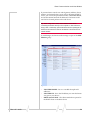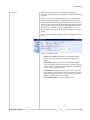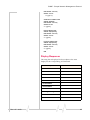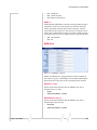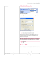
1
USAT
USATCORP.COM
Contact USATCORP.COM for more
information or quantity pricing
1-888-550-8728
Raven X 1x/EV-DO
User Guide
20070914
Rev 1.0C
Raven X 1x/EV-DO
User Guide
20070914
Rev 1.0C
Preface
Important Notice
Due to the nature of wireless communications, transmission and reception of data can never be guaranteed. Data may be delayed, corrupted (i.e., have errors) or be totally lost. Although significant delays or losses of data are rare when wireless devices such as the Sierra Wireless AirLink Raven X are used in a normal manner with a well‐constructed network, the Sierra Wireless AirLink Raven X should not be used in situations where failure to transmit or receive data could result in damage of any kind to the user or any other party, including but not limited to personal injury, death, or loss of property. Sierra Wireless accepts no responsibility for damages of any kind resulting from delays or errors in data transmitted or received using the Sierra Wireless AirLink Raven X, or for failure of the Sierra Wireless AirLink Raven X to transmit or receive such data.
Safety and Hazards
Do not operate the Sierra Wireless AirLink Raven X in areas where blasting is in progress, where explosive atmospheres may be present, near medical equipment, near life support equipment, or any equipment which may be susceptible to any form of radio interference. In such areas, the Sierra Wireless AirLink Raven X MUST BE POWERED OFF. The Sierra Wireless AirLink Raven X can transmit signals that could interfere with this equipment.
Do not operate the Sierra Wireless AirLink Raven X in any aircraft, whether the aircraft is on the ground or in flight. In aircraft, the Sierra Wireless AirLink Raven X MUST BE POWERED OFF. When operating, the Sierra Wireless AirLink Raven X can transmit signals that could interfere with various onboard systems.
Note: Some airlines may permit the use of cellular phones while the
aircraft is on the ground and the door is open. Sierra Wireless AirLink
Raven X may be used at this time.
The driver or operator of any vehicle should not operate the Sierra Wireless AirLink Raven X while in control of a vehicle. Doing so will detract from the driver or operatorʹs control and operation of that vehicle. In some states and provinces, operating such communications devices while in control of a vehicle is an offence.
Limitation of
Liability
Rev 1.0C Jul.09
The information in this manual is subject to change without notice and does not represent a commitment on the part of Sierra Wireless. SIERRA WIRELESS AND ITS AFFILIATES SPECIFICALLY DISCLAIM LIABILITY FOR ANY AND ALL 1
Preface
DIRECT, INDIRECT, SPECIAL, GENERAL, INCIDENTAL, CONSEQUENTIAL, PUNITIVE OR EXEMPLARY DAMAGES INCLUDING, BUT NOT LIMITED TO, LOSS OF PROFITS OR REVENUE OR ANTICIPATED PROFITS OR REVENUE ARISING OUT OF THE USE OR INABILITY TO USE ANY SIERRA WIRELESS PRODUCT, EVEN IF SIERRA WIRELESS AND/OR ITS AFFILIATES HAS BEEN ADVISED OF THE POSSIBILITY OF SUCH DAMAGES OR THEY ARE FORESEEABLE OR FOR CLAIMS BY ANY THIRD PARTY.
Notwithstanding the foregoing, in no event shall Sierra Wireless and/or its affiliates aggregate liability arising under or in connection with the Sierra Wireless product, regardless of the number of events, occurrences, or claims giving rise to liability, be in excess of the price paid by the purchaser for the Sierra Wireless product.
Patents
Portions of this product may be covered by some or all of the following US patents:
5,515,013
5,629,960
5,845,216
5,847,553
5,878,234
5,890,057
5,929,815
6,169,884
6,191,741
6,199,168
6,339,405
6,359,591
6,400,336
6,516,204
6,561,851
6,643,501
6,653,979
6,697,030
6,785,830
6,845,249
6,847,830
6,876,697
6,879,585
6,886,049
6,968,171
6,985,757
7,023,878
7,053,843
7,106,569
7,145,267
7,200,512
D442,170
D459,303
and other patents pending.
This product includes technology licensed from:
QUALCOMM® 3G
Licensed by QUALCOMM Incorporated under one or more of the following United States patents and/or their counterparts in other nations:
4,901,307
5,056,109
5,101,501
5,109,390
5,228,054
5,267,261
5,267,262
5,337,338
5,414,796
5,416,797
5,490,165
5,504,773
5,506,865
5,511,073
5,535,239
5,544,196
5,568,483
5,600,754
5,657,420
5,659,569
5,710,784
5,778,338
Manufactured or sold by Sierra Wireless or its licensees under one or more patents licensed from InterDigital Group.
Copyright
© 2009 Sierra Wireless. All rights reserved.
Trademarks
AirCard® and “Heart of the Wireless Machine®” are registered trademarks of Sierra Wireless. Watcher® is a trademark of Sierra Wireless, registered in the European Community. Rev 1.0C Jul.09
2
Preface
AirLink™ and AceWare™ are trademarks of Sierra Wireless.
Sierra Wireless, the Sierra Wireless logo, the red wave design, and the red‐tipped antenna are trademarks of Sierra Wireless.
Windows® is a registered trademark of Microsoft Corporation.
QUALCOMM® is a registered trademark of QUALCOMM Incorporated. Used under license.
Other trademarks are the property of the respective owners.
Contact
Information
Support Desk:
Phone: 1-877-231-1144
Hours: 5:00 AM to 5:00 PM Pacific Time,
Monday to Friday, except US Holidays
E-mail: [email protected]
Sales Desk:
Phone: 1-510-624-4200
1-604-232-1488
Hours: 8:00 AM to 5:00 PM Pacific Time
E-mail: [email protected]
Post: Sierra Wireless America
39677 Eureka Drive
Newark, CA
USA
94560
Sierra Wireless
13811 Wireless Way
Richmond, BC
Canada
V6V 3A4
Fax: 1-510-624-4299
1-604-231-1109
Web: www.sierrawireless.com
Consult our website for up‐to‐date product descriptions, documentation, application notes, firmware upgrades, trouble‐
shooting tips, and press releases:
www.sierrawireless.com
Rev 1.0C Jul.09
3
Preface
Revision
number
Release
date
Changes
1.x
2003-2005
AirLink Communications documentation - CDPD, CDMA, and GPRS.
2.x
Q2: 2005-Q2:
2007
AirLink Communications documentation - CDMA, EV-DO, EDGE, and
HSUPA/HSDPA.
3.0
Q2: 2008
Converted documentation from AirLink Communications documentation
format into Sierra Wireless documentation format. Phase II of the conversion
completed.
Raven modem line documentation is revised.
Rev 1.0C Jul.09
4
Contents
Introduction to the Raven X . . . . . . . . . . . . . . . . . . . . . . . . . . . . . . . . . . . . . . . . . . .8
ALEOS™ . . . . . . . . . . . . . . . . . . . . . . . . . . . . . . . . . . . . . . . . . . . . . . . . . . . . . . . . . . . . . . . . . . . . . . . 8
AceWare™. . . . . . . . . . . . . . . . . . . . . . . . . . . . . . . . . . . . . . . . . . . . . . . . . . . . . . . . . . . . . . . . . . . . . . 9
AceManager . . . . . . . . . . . . . . . . . . . . . . . . . . . . . . . . . . . . . . . . . . . . . . . . . . . . . . . . . . . . . . . . . . . . . . . . . 9
Simplified Deployment . . . . . . . . . . . . . . . . . . . . . . . . . . . . . . . . . . . . . . . . . . . . . . . . . . . . . . . . . . . 10
Monitor and Control . . . . . . . . . . . . . . . . . . . . . . . . . . . . . . . . . . . . . . . . . . . . . . . . . . . . . . . . . . . . . 10
AceNet . . . . . . . . . . . . . . . . . . . . . . . . . . . . . . . . . . . . . . . . . . . . . . . . . . . . . . . . . . . . . . . . . . . . . . . . . . . . . 10
Network Monitoring . . . . . . . . . . . . . . . . . . . . . . . . . . . . . . . . . . . . . . . . . . . . . . . . . . . . . . . . . . . . . 11
AceView . . . . . . . . . . . . . . . . . . . . . . . . . . . . . . . . . . . . . . . . . . . . . . . . . . . . . . . . . . . . . . . . . . . . . . . . . . . . 11
Modem Doctor . . . . . . . . . . . . . . . . . . . . . . . . . . . . . . . . . . . . . . . . . . . . . . . . . . . . . . . . . . . . . . . . . . . . . . 11
Modem Doctor USB . . . . . . . . . . . . . . . . . . . . . . . . . . . . . . . . . . . . . . . . . . . . . . . . . . . . . . . . . . . . . . . . . . 12
Connecting to your cellular Network . . . . . . . . . . . . . . . . . . . . . . . . . . . . . . . . . . . . . . . . . . . . . . 13
Steps of a connection: . . . . . . . . . . . . . . . . . . . . . . . . . . . . . . . . . . . . . . . . . . . . . . . . . . . . . . . . . . . 13
Dynamic vs. Static IP Addresses . . . . . . . . . . . . . . . . . . . . . . . . . . . . . . . . . . . . . . . . . . . . . . . . . . . . . . . 14
EV-DO . . . . . . . . . . . . . . . . . . . . . . . . . . . . . . . . . . . . . . . . . . . . . . . . . . . . . . . . . . . . . . . . . . . . . . . 15
Security . . . . . . . . . . . . . . . . . . . . . . . . . . . . . . . . . . . . . . . . . . . . . . . . . . . . . . . . . . . . . . . . . . . . . . . . 16
Specifications . . . . . . . . . . . . . . . . . . . . . . . . . . . . . . . . . . . . . . . . . . . . . . . . . . . . . .17
Features and Benefits . . . . . . . . . . . . . . . . . . . . . . . . . . . . . . . . . . . . . . . . . . . . . . . . . . . . . . . . . . . .
Technology . . . . . . . . . . . . . . . . . . . . . . . . . . . . . . . . . . . . . . . . . . . . . . . . . . . . . . . . . . . . . . . . . . . . .
Bands. . . . . . . . . . . . . . . . . . . . . . . . . . . . . . . . . . . . . . . . . . . . . . . . . . . . . . . . . . . . . . . . . . . . . . . . . .
Environmental . . . . . . . . . . . . . . . . . . . . . . . . . . . . . . . . . . . . . . . . . . . . . . . . . . . . . . . . . . . . . . . . . .
Power Consumption: (@12V DC) . . . . . . . . . . . . . . . . . . . . . . . . . . . . . . . . . . . . . . . . . . . . . . . . . .
Standards/Approvals. . . . . . . . . . . . . . . . . . . . . . . . . . . . . . . . . . . . . . . . . . . . . . . . . . . . . . . . . . . . .
Host Interfaces. . . . . . . . . . . . . . . . . . . . . . . . . . . . . . . . . . . . . . . . . . . . . . . . . . . . . . . . . . . . . . . . . .
Dimensions. . . . . . . . . . . . . . . . . . . . . . . . . . . . . . . . . . . . . . . . . . . . . . . . . . . . . . . . . . . . . . . . . . . . .
Application Interfaces. . . . . . . . . . . . . . . . . . . . . . . . . . . . . . . . . . . . . . . . . . . . . . . . . . . . . . . . . . . .
LED Indicators . . . . . . . . . . . . . . . . . . . . . . . . . . . . . . . . . . . . . . . . . . . . . . . . . . . . . . . . . . . . . . . . . .
17
17
17
17
17
17
18
18
18
18
Interface Port Pin-Outs . . . . . . . . . . . . . . . . . . . . . . . . . . . . . . . . . . . . . . . . . . . . . . . . . . . . . . . . . . 19
Serial Port . . . . . . . . . . . . . . . . . . . . . . . . . . . . . . . . . . . . . . . . . . . . . . . . . . . . . . . . . . . . . . . . . . . . . . 19
Power Connector . . . . . . . . . . . . . . . . . . . . . . . . . . . . . . . . . . . . . . . . . . . . . . . . . . . . . . . . . . . . . . . 19
Activating your Raven X on your cellular Network . . . . . . . . . . . . . . . . . . . . .20
Activating Using AT Commands . . . . . . . . . . . . . . . . . . . . . . . . . . . . . . . . . . . . . . . . . . . . . . . . . . 20
Using Direct Commands to the Internal Hardware . . . . . . . . . . . . . . . . . . . . . . . . . . . . . . . . . . . . . . . . 21
Activating the Modem. . . . . . . . . . . . . . . . . . . . . . . . . . . . . . . . . . . . . . . . . . . . . . . . . . . . . . . . . . . . 21
Private Networking . . . . . . . . . . . . . . . . . . . . . . . . . . . . . . . . . . . . . . . . . . . . . . . . . . . . . . . . . . . . . . . . . . . 22
Hardware Installation of the Raven X . . . . . . . . . . . . . . . . . . . . . . . . . . . . . . . . .24
Connecting to Power . . . . . . . . . . . . . . . . . . . . . . . . . . . . . . . . . . . . . . . . . . . . . . . . . . . . . . . . . . . 25
Rev 1.0C Jul.09
1
Contents
Connecting to a Computer or other Device . . . . . . . . . . . . . . . . . . . . . . . . . . . . . . . . . . . . . . . . 26
Indicator Lights . . . . . . . . . . . . . . . . . . . . . . . . . . . . . . . . . . . . . . . . . . . . . . . . . . . . . . . . . . . . . . . . 26
Light Patterns. . . . . . . . . . . . . . . . . . . . . . . . . . . . . . . . . . . . . . . . . . . . . . . . . . . . . . . . . . . . . . . . . . . 27
Mounting. . . . . . . . . . . . . . . . . . . . . . . . . . . . . . . . . . . . . . . . . . . . . . . . . . . . . . . . . . . . . . . . . . . . . . 28
Configuring your Raven X . . . . . . . . . . . . . . . . . . . . . . . . . . . . . . . . . . . . . . . . . . .29
Using AceManager . . . . . . . . . . . . . . . . . . . . . . . . . . . . . . . . . . . . . . . . . . . . . . . . . . . . . . . . . . . . . 29
Using Templates . . . . . . . . . . . . . . . . . . . . . . . . . . . . . . . . . . . . . . . . . . . . . . . . . . . . . . . . . . . . . . . 32
Using a Terminal Application with AT Commands . . . . . . . . . . . . . . . . . . . . . . . . . . . . . . . . . . 37
AT Commands . . . . . . . . . . . . . . . . . . . . . . . . . . . . . . . . . . . . . . . . . . . . . . . . . . . . . . . . . . . . . . . . . . . . . . 41
Data Communication and Host Modes . . . . . . . . . . . . . . . . . . . . . . . . . . . . . . . .42
Basic Modes . . . . . . . . . . . . . . . . . . . . . . . . . . . . . . . . . . . . . . . . . . . . . . . . . . . . . . . . . . . . . . . . . . . . 42
Serial Modes. . . . . . . . . . . . . . . . . . . . . . . . . . . . . . . . . . . . . . . . . . . . . . . . . . . . . . . . . . . . . . . . . . . . 42
Data Communication . . . . . . . . . . . . . . . . . . . . . . . . . . . . . . . . . . . . . . . . . . . . . . . . . . . . . . . . . . . . 43
Basic Modes . . . . . . . . . . . . . . . . . . . . . . . . . . . . . . . . . . . . . . . . . . . . . . . . . . . . . . . . . . . . . . . . . . . 43
Start up Mode . . . . . . . . . . . . . . . . . . . . . . . . . . . . . . . . . . . . . . . . . . . . . . . . . . . . . . . . . . . . . . . . . . . . . . . 43
AT Mode . . . . . . . . . . . . . . . . . . . . . . . . . . . . . . . . . . . . . . . . . . . . . . . . . . . . . . . . . . . . . . . . . . . . . . . . . . . . 44
PassThru Mode . . . . . . . . . . . . . . . . . . . . . . . . . . . . . . . . . . . . . . . . . . . . . . . . . . . . . . . . . . . . . . . . . . . . . . 45
Telnet Mode . . . . . . . . . . . . . . . . . . . . . . . . . . . . . . . . . . . . . . . . . . . . . . . . . . . . . . . . . . . . . . . . . . . . . . . . . 46
Serial Modes . . . . . . . . . . . . . . . . . . . . . . . . . . . . . . . . . . . . . . . . . . . . . . . . . . . . . . . . . . . . . . . . . . . . . . . . 47
PPP . . . . . . . . . . . . . . . . . . . . . . . . . . . . . . . . . . . . . . . . . . . . . . . . . . . . . . . . . . . . . . . . . . . . . . . . . . . . . . . . 47
Link Radio Coverage . . . . . . . . . . . . . . . . . . . . . . . . . . . . . . . . . . . . . . . . . . . . . . . . . . . . . . . . . . . . . 49
SLIP . . . . . . . . . . . . . . . . . . . . . . . . . . . . . . . . . . . . . . . . . . . . . . . . . . . . . . . . . . . . . . . . . . . . . . . . . . . . . . . 49
UDP Auto Answer . . . . . . . . . . . . . . . . . . . . . . . . . . . . . . . . . . . . . . . . . . . . . . . . . . . . . . . . . . . . . . . 50
Reliable UDP . . . . . . . . . . . . . . . . . . . . . . . . . . . . . . . . . . . . . . . . . . . . . . . . . . . . . . . . . . . . . . . . . . . 51
UDP Multicast Mode . . . . . . . . . . . . . . . . . . . . . . . . . . . . . . . . . . . . . . . . . . . . . . . . . . . . . . . . . . . . . 51
Hybrid Modes . . . . . . . . . . . . . . . . . . . . . . . . . . . . . . . . . . . . . . . . . . . . . . . . . . . . . . . . . . . . . . . . . . . . . . . 53
Data Communication . . . . . . . . . . . . . . . . . . . . . . . . . . . . . . . . . . . . . . . . . . . . . . . . . . . . . . . . . . . 53
Public and Private Mode . . . . . . . . . . . . . . . . . . . . . . . . . . . . . . . . . . . . . . . . . . . . . . . . . . . . . . . . . . . . . . 53
Internal DHCP Server . . . . . . . . . . . . . . . . . . . . . . . . . . . . . . . . . . . . . . . . . . . . . . . . . . . . . . . . . . . . 55
Additional Connected Networks . . . . . . . . . . . . . . . . . . . . . . . . . . . . . . . . . . . . . . . . . . . . . . . . . . . 56
Basic Routing . . . . . . . . . . . . . . . . . . . . . . . . . . . . . . . . . . . . . . . . . . . . . . . . . . . . . . . . . . . . . . . . . . . . . . . 56
Port Forwarding . . . . . . . . . . . . . . . . . . . . . . . . . . . . . . . . . . . . . . . . . . . . . . . . . . . . . . . . . . . . . . . . . 56
Firewall Functions . . . . . . . . . . . . . . . . . . . . . . . . . . . . . . . . . . . . . . . . . . . . . . . . . . . . . . . . . . . . . . . 58
VPN . . . . . . . . . . . . . . . . . . . . . . . . . . . . . . . . . . . . . . . . . . . . . . . . . . . . . . . . . . . . . . . . . . . . . . . . . . 61
Split Tunnel . . . . . . . . . . . . . . . . . . . . . . . . . . . . . . . . . . . . . . . . . . . . . . . . . . . . . . . . . . . . . . . . . . . . . . . . . 62
VPN 1 . . . . . . . . . . . . . . . . . . . . . . . . . . . . . . . . . . . . . . . . . . . . . . . . . . . . . . . . . . . . . . . . . . . . . . . . . . . . . . 63
GRE configuration . . . . . . . . . . . . . . . . . . . . . . . . . . . . . . . . . . . . . . . . . . . . . . . . . . . . . . . . . . . . . . . . . . . 66
Keepalive . . . . . . . . . . . . . . . . . . . . . . . . . . . . . . . . . . . . . . . . . . . . . . . . . . . . . . . . . . . . . . . . . . . . . . . . . . . 66
Configuring Keepalive . . . . . . . . . . . . . . . . . . . . . . . . . . . . . . . . . . . . . . . . . . . . . . . . . . . . . . . . . . . 67
Data usage using Keepalive. . . . . . . . . . . . . . . . . . . . . . . . . . . . . . . . . . . . . . . . . . . . . . . . . . . . . . . 68
Rev 1.0C Jul.09
2
Contents
IP Manager . . . . . . . . . . . . . . . . . . . . . . . . . . . . . . . . . . . . . . . . . . . . . . . . . . . . . . . . .69
Reasons to contact the modem and/or the connected device: . . . . . . . . . . . . . . . . . . . . . . . . . 69
Understanding Domain Names. . . . . . . . . . . . . . . . . . . . . . . . . . . . . . . . . . . . . . . . . . . . . . . . . . . 70
car54.mydomain.com . . . . . . . . . . . . . . . . . . . . . . . . . . . . . . . . . . . . . . . . . . . . . . . . . . . . . . . . . . . . 71
car54.mydomain.com.ca. . . . . . . . . . . . . . . . . . . . . . . . . . . . . . . . . . . . . . . . . . . . . . . . . . . . . . . . . . 71
Dynamic Names . . . . . . . . . . . . . . . . . . . . . . . . . . . . . . . . . . . . . . . . . . . . . . . . . . . . . . . . . . . . . . . . . . . . . 71
Using IP Manager with your Raven X. . . . . . . . . . . . . . . . . . . . . . . . . . . . . . . . . . . . . . . . . . . . . . 72
Restrictions for Modem Name. . . . . . . . . . . . . . . . . . . . . . . . . . . . . . . . . . . . . . . . . . . . . . . . . . . . . 73
Data Usage for IP Manager Server Updates . . . . . . . . . . . . . . . . . . . . . . . . . . . . . . . . . . . . . . . . . . . . . 73
Eairlink.com . . . . . . . . . . . . . . . . . . . . . . . . . . . . . . . . . . . . . . . . . . . . . . . . . . . . . . . . . . . . . . . . . . . . . . . . . 74
Understanding DNS . . . . . . . . . . . . . . . . . . . . . . . . . . . . . . . . . . . . . . . . . . . . . . . . . . . . . . . . . . . . 74
Configuring DNS . . . . . . . . . . . . . . . . . . . . . . . . . . . . . . . . . . . . . . . . . . . . . . . . . . . . . . . . . . . . . . . . . . . . 74
The “PPP-Peer” Domain Name . . . . . . . . . . . . . . . . . . . . . . . . . . . . . . . . . . . . . . . . . . . . . . . . . . . . . . . . 76
Configuring Modbus/BSAP . . . . . . . . . . . . . . . . . . . . . . . . . . . . . . . . . . . . . . . . . .77
Modbus Overview . . . . . . . . . . . . . . . . . . . . . . . . . . . . . . . . . . . . . . . . . . . . . . . . . . . . . . . . . . . . . . . . . . . . 77
Telemetry . . . . . . . . . . . . . . . . . . . . . . . . . . . . . . . . . . . . . . . . . . . . . . . . . . . . . . . . . . . . . . . . . . . . . . 77
Remote Terminal Unit (RTU) . . . . . . . . . . . . . . . . . . . . . . . . . . . . . . . . . . . . . . . . . . . . . . . . . . . . . . 77
Supervisory Control and Data Acquisition (SCADA) . . . . . . . . . . . . . . . . . . . . . . . . . . . . . . . . . . 78
Programmable Logic Controller (PLC) . . . . . . . . . . . . . . . . . . . . . . . . . . . . . . . . . . . . . . . . . . . . . . 78
Modbus TCP/IP . . . . . . . . . . . . . . . . . . . . . . . . . . . . . . . . . . . . . . . . . . . . . . . . . . . . . . . . . . . . . . . . . 78
Raven Modbus on UDP. . . . . . . . . . . . . . . . . . . . . . . . . . . . . . . . . . . . . . . . . . . . . . . . . . . . . . . . . . . 78
Configuring the Raven X at the Polling Host for Modbus on UDP . . . . . . . . . . . . . . . . . . . . . 79
Configuring the Remote Raven Xs for Modbus with UDP . . . . . . . . . . . . . . . . . . . . . . . . . . . . 82
SNMP : Simple Network Management Protocol . . . . . . . . . . . . . . . . . . . . . . .87
Management Information Base (MIB) . . . . . . . . . . . . . . . . . . . . . . . . . . . . . . . . . . . . . . . . . . . . . . . . . . 87
SNMP Traps . . . . . . . . . . . . . . . . . . . . . . . . . . . . . . . . . . . . . . . . . . . . . . . . . . . . . . . . . . . . . . . . . . . . . . . . 87
SNMP Configuration . . . . . . . . . . . . . . . . . . . . . . . . . . . . . . . . . . . . . . . . . . . . . . . . . . . . . . . . . . . . 88
Listening Port . . . . . . . . . . . . . . . . . . . . . . . . . . . . . . . . . . . . . . . . . . . . . . . . . . . . . . . . . . . . . . . . . . . . . . . 89
Security Level . . . . . . . . . . . . . . . . . . . . . . . . . . . . . . . . . . . . . . . . . . . . . . . . . . . . . . . . . . . . . . . . . . . . . . . 89
User Name and Password . . . . . . . . . . . . . . . . . . . . . . . . . . . . . . . . . . . . . . . . . . . . . . . . . . . . . . . . . . . . . 89
Trap Destination . . . . . . . . . . . . . . . . . . . . . . . . . . . . . . . . . . . . . . . . . . . . . . . . . . . . . . . . . . . . . . . . . . . . . 90
Community String . . . . . . . . . . . . . . . . . . . . . . . . . . . . . . . . . . . . . . . . . . . . . . . . . . . . . . . . . . . . . . . . . . . 91
SNMP MIB Definition Sample. . . . . . . . . . . . . . . . . . . . . . . . . . . . . . . . . . . . . . . . . . . . . . . . . . . . 91
Display Responses . . . . . . . . . . . . . . . . . . . . . . . . . . . . . . . . . . . . . . . . . . . . . . . . . . . . . . . . . . . . . . . . . . . 95
Product ID . . . . . . . . . . . . . . . . . . . . . . . . . . . . . . . . . . . . . . . . . . . . . . . . . . . . . . . . . . . . . . . . . . . . . . . . . . 96
Configuration Commands . . . . . . . . . . . . . . . . . . . . . . . . . . . . . . . . . . . . . . . . . . 97
Info (information). . . . . . . . . . . . . . . . . . . . . . . . . . . . . . . . . . . . . . . . . . . . . . . . . . . . . . . . . . . . . . . 97
*DEVICEID? . . . . . . . . . . . . . . . . . . . . . . . . . . . . . . . . . . . . . . . . . . . . . . . . . . . . . . . . . . . . . . . . . . . . 98
*ETHMAC? . . . . . . . . . . . . . . . . . . . . . . . . . . . . . . . . . . . . . . . . . . . . . . . . . . . . . . . . . . . . . . . . . . . . . 98
Rev 1.0C Jul.09
3
Contents
*NETPHONE?. . . . . . . . . . . . . . . . . . . . . . . . . . . . . . . . . . . . . . . . . . . . . . . . . . . . . . . . . . . . . . . . . . . 98
&V . . . . . . . . . . . . . . . . . . . . . . . . . . . . . . . . . . . . . . . . . . . . . . . . . . . . . . . . . . . . . . . . . . . . . . . . . . . . . 98
In . . . . . . . . . . . . . . . . . . . . . . . . . . . . . . . . . . . . . . . . . . . . . . . . . . . . . . . . . . . . . . . . . . . . . . . . . . . . . 98
Information Displayed in AceManager without AT Commands Listed . . . . . . . . . . . . . . . . . . . . . . . 99
Status . . . . . . . . . . . . . . . . . . . . . . . . . . . . . . . . . . . . . . . . . . . . . . . . . . . . . . . . . . . . . . . . . . . . . . . . 99
*BOARDTEMP? . . . . . . . . . . . . . . . . . . . . . . . . . . . . . . . . . . . . . . . . . . . . . . . . . . . . . . . . . . . . . . . . 100
*HOSTMODE? . . . . . . . . . . . . . . . . . . . . . . . . . . . . . . . . . . . . . . . . . . . . . . . . . . . . . . . . . . . . . . . . . 100
*NETCHAN? . . . . . . . . . . . . . . . . . . . . . . . . . . . . . . . . . . . . . . . . . . . . . . . . . . . . . . . . . . . . . . . . . . . 100
*NETERR?. . . . . . . . . . . . . . . . . . . . . . . . . . . . . . . . . . . . . . . . . . . . . . . . . . . . . . . . . . . . . . . . . . . . . 100
*NETIP?. . . . . . . . . . . . . . . . . . . . . . . . . . . . . . . . . . . . . . . . . . . . . . . . . . . . . . . . . . . . . . . . . . . . . . . 100
*NETOP? . . . . . . . . . . . . . . . . . . . . . . . . . . . . . . . . . . . . . . . . . . . . . . . . . . . . . . . . . . . . . . . . . . . . . . 100
*NETRSSI? . . . . . . . . . . . . . . . . . . . . . . . . . . . . . . . . . . . . . . . . . . . . . . . . . . . . . . . . . . . . . . . . . . . . 100
*NETSERV?. . . . . . . . . . . . . . . . . . . . . . . . . . . . . . . . . . . . . . . . . . . . . . . . . . . . . . . . . . . . . . . . . . . . 100
*NETSTATE?. . . . . . . . . . . . . . . . . . . . . . . . . . . . . . . . . . . . . . . . . . . . . . . . . . . . . . . . . . . . . . . . . . . 100
*PRLSTATUS? . . . . . . . . . . . . . . . . . . . . . . . . . . . . . . . . . . . . . . . . . . . . . . . . . . . . . . . . . . . . . . . . . 101
*POWERIN? . . . . . . . . . . . . . . . . . . . . . . . . . . . . . . . . . . . . . . . . . . . . . . . . . . . . . . . . . . . . . . . . . . . 101
+HWTEMP? . . . . . . . . . . . . . . . . . . . . . . . . . . . . . . . . . . . . . . . . . . . . . . . . . . . . . . . . . . . . . . . . . . . 101
+PRL? . . . . . . . . . . . . . . . . . . . . . . . . . . . . . . . . . . . . . . . . . . . . . . . . . . . . . . . . . . . . . . . . . . . . . . . . 101
Information Displayed in AceManager without AT Commands Listed . . . . . . . . . . . . . . . . . . . . . . 101
AT Commands Requiring PassThru mode . . . . . . . . . . . . . . . . . . . . . . . . . . . . . . . . . . . . . . . . . . . . . . 102
+GSN . . . . . . . . . . . . . . . . . . . . . . . . . . . . . . . . . . . . . . . . . . . . . . . . . . . . . . . . . . . . . . . . . . . . . . . . 102
Common . . . . . . . . . . . . . . . . . . . . . . . . . . . . . . . . . . . . . . . . . . . . . . . . . . . . . . . . . . . . . . . . . . . . . 102
Misc (Miscellaneous) . . . . . . . . . . . . . . . . . . . . . . . . . . . . . . . . . . . . . . . . . . . . . . . . . . . . . . . . . . . . . . . . 102
Enable Event Reporting = n. . . . . . . . . . . . . . . . . . . . . . . . . . . . . . . . . . . . . . . . . . . . . . . . . . . . . . 102
+++ . . . . . . . . . . . . . . . . . . . . . . . . . . . . . . . . . . . . . . . . . . . . . . . . . . . . . . . . . . . . . . . . . . . . . . . . . 102
A/ . . . . . . . . . . . . . . . . . . . . . . . . . . . . . . . . . . . . . . . . . . . . . . . . . . . . . . . . . . . . . . . . . . . . . . . . . . . . 102
A . . . . . . . . . . . . . . . . . . . . . . . . . . . . . . . . . . . . . . . . . . . . . . . . . . . . . . . . . . . . . . . . . . . . . . . . . . . . . 103
D[method][d.d.d.d][/ppppp] or D[method][@name][/ppppp] . . . . . . . . . . . . . . . . . . . . . . . . . 103
DS=n . . . . . . . . . . . . . . . . . . . . . . . . . . . . . . . . . . . . . . . . . . . . . . . . . . . . . . . . . . . . . . . . . . . . . . . . . 103
Hn. . . . . . . . . . . . . . . . . . . . . . . . . . . . . . . . . . . . . . . . . . . . . . . . . . . . . . . . . . . . . . . . . . . . . . . . . . . . 104
O . . . . . . . . . . . . . . . . . . . . . . . . . . . . . . . . . . . . . . . . . . . . . . . . . . . . . . . . . . . . . . . . . . . . . . . . . . . . . 104
OPRG=n . . . . . . . . . . . . . . . . . . . . . . . . . . . . . . . . . . . . . . . . . . . . . . . . . . . . . . . . . . . . . . . . . . . . . . 104
S53=[method][d.d.d.d][/ppppp] . . . . . . . . . . . . . . . . . . . . . . . . . . . . . . . . . . . . . . . . . . . . . . . . . . 104
Z . . . . . . . . . . . . . . . . . . . . . . . . . . . . . . . . . . . . . . . . . . . . . . . . . . . . . . . . . . . . . . . . . . . . . . . . . . . . . 104
&W . . . . . . . . . . . . . . . . . . . . . . . . . . . . . . . . . . . . . . . . . . . . . . . . . . . . . . . . . . . . . . . . . . . . . . . . . . . 105
*DATE=[mm/dd/yyyy],[hh:mm:ss]. . . . . . . . . . . . . . . . . . . . . . . . . . . . . . . . . . . . . . . . . . . . . . . . 105
*DPORT=n . . . . . . . . . . . . . . . . . . . . . . . . . . . . . . . . . . . . . . . . . . . . . . . . . . . . . . . . . . . . . . . . . . . . 105
*HOSTPAP=n . . . . . . . . . . . . . . . . . . . . . . . . . . . . . . . . . . . . . . . . . . . . . . . . . . . . . . . . . . . . . . . . . 105
*NETALLOWZEROIP=n . . . . . . . . . . . . . . . . . . . . . . . . . . . . . . . . . . . . . . . . . . . . . . . . . . . . . . . . . 105
*NETPW=pw . . . . . . . . . . . . . . . . . . . . . . . . . . . . . . . . . . . . . . . . . . . . . . . . . . . . . . . . . . . . . . . . . . 105
*NETPHONE?. . . . . . . . . . . . . . . . . . . . . . . . . . . . . . . . . . . . . . . . . . . . . . . . . . . . . . . . . . . . . . . . . . 105
*NETROAMPREF=n . . . . . . . . . . . . . . . . . . . . . . . . . . . . . . . . . . . . . . . . . . . . . . . . . . . . . . . . . . . . 105
*NETUID=uid. . . . . . . . . . . . . . . . . . . . . . . . . . . . . . . . . . . . . . . . . . . . . . . . . . . . . . . . . . . . . . . . . . 106
*STATICIP=d.d.d.d . . . . . . . . . . . . . . . . . . . . . . . . . . . . . . . . . . . . . . . . . . . . . . . . . . . . . . . . . . . . . 106
*STATUSCHK=n. . . . . . . . . . . . . . . . . . . . . . . . . . . . . . . . . . . . . . . . . . . . . . . . . . . . . . . . . . . . . . . 106
Serial . . . . . . . . . . . . . . . . . . . . . . . . . . . . . . . . . . . . . . . . . . . . . . . . . . . . . . . . . . . . . . . . . . . . . . . . . . . . . 106
En . . . . . . . . . . . . . . . . . . . . . . . . . . . . . . . . . . . . . . . . . . . . . . . . . . . . . . . . . . . . . . . . . . . . . . . . . . . . 107
Qn. . . . . . . . . . . . . . . . . . . . . . . . . . . . . . . . . . . . . . . . . . . . . . . . . . . . . . . . . . . . . . . . . . . . . . . . . . . . 107
S3=n . . . . . . . . . . . . . . . . . . . . . . . . . . . . . . . . . . . . . . . . . . . . . . . . . . . . . . . . . . . . . . . . . . . . . . . . . 107
S4=n . . . . . . . . . . . . . . . . . . . . . . . . . . . . . . . . . . . . . . . . . . . . . . . . . . . . . . . . . . . . . . . . . . . . . . . . . 107
S5=n . . . . . . . . . . . . . . . . . . . . . . . . . . . . . . . . . . . . . . . . . . . . . . . . . . . . . . . . . . . . . . . . . . . . . . . . . 108
Rev 1.0C Jul.09
4
Contents
S6=n . . . . . . . . . . . . . . . . . . . . . . . . . . . . . . . . . . . . . . . . . . . . . . . . . . . . . . . . . . . . . . . . . . . . . . . . . 108
S8=n . . . . . . . . . . . . . . . . . . . . . . . . . . . . . . . . . . . . . . . . . . . . . . . . . . . . . . . . . . . . . . . . . . . . . . . . . 108
S9=n . . . . . . . . . . . . . . . . . . . . . . . . . . . . . . . . . . . . . . . . . . . . . . . . . . . . . . . . . . . . . . . . . . . . . . . . . 108
S10=n . . . . . . . . . . . . . . . . . . . . . . . . . . . . . . . . . . . . . . . . . . . . . . . . . . . . . . . . . . . . . . . . . . . . . . . . 108
S23=[speed],[databits][parity][stop bits] . . . . . . . . . . . . . . . . . . . . . . . . . . . . . . . . . . . . . . . . . . 108
S50=n . . . . . . . . . . . . . . . . . . . . . . . . . . . . . . . . . . . . . . . . . . . . . . . . . . . . . . . . . . . . . . . . . . . . . . . . 109
S51=n . . . . . . . . . . . . . . . . . . . . . . . . . . . . . . . . . . . . . . . . . . . . . . . . . . . . . . . . . . . . . . . . . . . . . . . . 109
S211=n . . . . . . . . . . . . . . . . . . . . . . . . . . . . . . . . . . . . . . . . . . . . . . . . . . . . . . . . . . . . . . . . . . . . . . . 109
Vn . . . . . . . . . . . . . . . . . . . . . . . . . . . . . . . . . . . . . . . . . . . . . . . . . . . . . . . . . . . . . . . . . . . . . . . . . . . . 109
Xn . . . . . . . . . . . . . . . . . . . . . . . . . . . . . . . . . . . . . . . . . . . . . . . . . . . . . . . . . . . . . . . . . . . . . . . . . . . . 109
&Cn . . . . . . . . . . . . . . . . . . . . . . . . . . . . . . . . . . . . . . . . . . . . . . . . . . . . . . . . . . . . . . . . . . . . . . . . . . 109
&Dn . . . . . . . . . . . . . . . . . . . . . . . . . . . . . . . . . . . . . . . . . . . . . . . . . . . . . . . . . . . . . . . . . . . . . . . . . . 110
&Sn. . . . . . . . . . . . . . . . . . . . . . . . . . . . . . . . . . . . . . . . . . . . . . . . . . . . . . . . . . . . . . . . . . . . . . . . . . . 110
\APPP . . . . . . . . . . . . . . . . . . . . . . . . . . . . . . . . . . . . . . . . . . . . . . . . . . . . . . . . . . . . . . . . . . . . . . . . 110
\ASLIP . . . . . . . . . . . . . . . . . . . . . . . . . . . . . . . . . . . . . . . . . . . . . . . . . . . . . . . . . . . . . . . . . . . . . . . . 110
\Qn . . . . . . . . . . . . . . . . . . . . . . . . . . . . . . . . . . . . . . . . . . . . . . . . . . . . . . . . . . . . . . . . . . . . . . . . . . . 110
*CTSE=n. . . . . . . . . . . . . . . . . . . . . . . . . . . . . . . . . . . . . . . . . . . . . . . . . . . . . . . . . . . . . . . . . . . . . . 110
*NUMTOIP=n . . . . . . . . . . . . . . . . . . . . . . . . . . . . . . . . . . . . . . . . . . . . . . . . . . . . . . . . . . . . . . . . . 111
*PPPNOCARRIER=n . . . . . . . . . . . . . . . . . . . . . . . . . . . . . . . . . . . . . . . . . . . . . . . . . . . . . . . . . . . 111
TCP . . . . . . . . . . . . . . . . . . . . . . . . . . . . . . . . . . . . . . . . . . . . . . . . . . . . . . . . . . . . . . . . . . . . . . . . . . . . . . . 111
S0=n . . . . . . . . . . . . . . . . . . . . . . . . . . . . . . . . . . . . . . . . . . . . . . . . . . . . . . . . . . . . . . . . . . . . . . . . . 111
S7=n . . . . . . . . . . . . . . . . . . . . . . . . . . . . . . . . . . . . . . . . . . . . . . . . . . . . . . . . . . . . . . . . . . . . . . . . . 112
S60=n . . . . . . . . . . . . . . . . . . . . . . . . . . . . . . . . . . . . . . . . . . . . . . . . . . . . . . . . . . . . . . . . . . . . . . . . 112
S221=n . . . . . . . . . . . . . . . . . . . . . . . . . . . . . . . . . . . . . . . . . . . . . . . . . . . . . . . . . . . . . . . . . . . . . . . 112
TCPS=n . . . . . . . . . . . . . . . . . . . . . . . . . . . . . . . . . . . . . . . . . . . . . . . . . . . . . . . . . . . . . . . . . . . . . . 112
TCPT=n. . . . . . . . . . . . . . . . . . . . . . . . . . . . . . . . . . . . . . . . . . . . . . . . . . . . . . . . . . . . . . . . . . . . . . . 112
*ENQ=n . . . . . . . . . . . . . . . . . . . . . . . . . . . . . . . . . . . . . . . . . . . . . . . . . . . . . . . . . . . . . . . . . . . . . . 112
UDP . . . . . . . . . . . . . . . . . . . . . . . . . . . . . . . . . . . . . . . . . . . . . . . . . . . . . . . . . . . . . . . . . . . . . . . . . . . . . . 113
AIP=n . . . . . . . . . . . . . . . . . . . . . . . . . . . . . . . . . . . . . . . . . . . . . . . . . . . . . . . . . . . . . . . . . . . . . . . . 113
HOR=n . . . . . . . . . . . . . . . . . . . . . . . . . . . . . . . . . . . . . . . . . . . . . . . . . . . . . . . . . . . . . . . . . . . . . . . 113
MDhh . . . . . . . . . . . . . . . . . . . . . . . . . . . . . . . . . . . . . . . . . . . . . . . . . . . . . . . . . . . . . . . . . . . . . . . . . 113
S82=n . . . . . . . . . . . . . . . . . . . . . . . . . . . . . . . . . . . . . . . . . . . . . . . . . . . . . . . . . . . . . . . . . . . . . . . . 113
S83=n . . . . . . . . . . . . . . . . . . . . . . . . . . . . . . . . . . . . . . . . . . . . . . . . . . . . . . . . . . . . . . . . . . . . . . . . 114
*DU=n. . . . . . . . . . . . . . . . . . . . . . . . . . . . . . . . . . . . . . . . . . . . . . . . . . . . . . . . . . . . . . . . . . . . . . . . 114
*UALL=n. . . . . . . . . . . . . . . . . . . . . . . . . . . . . . . . . . . . . . . . . . . . . . . . . . . . . . . . . . . . . . . . . . . . . . 114
*UDPLAST=n . . . . . . . . . . . . . . . . . . . . . . . . . . . . . . . . . . . . . . . . . . . . . . . . . . . . . . . . . . . . . . . . . 114
*USD=n . . . . . . . . . . . . . . . . . . . . . . . . . . . . . . . . . . . . . . . . . . . . . . . . . . . . . . . . . . . . . . . . . . . . . . 114
DNS . . . . . . . . . . . . . . . . . . . . . . . . . . . . . . . . . . . . . . . . . . . . . . . . . . . . . . . . . . . . . . . . . . . . . . . . . . . . . . 115
*DNSn=d.d.d.d . . . . . . . . . . . . . . . . . . . . . . . . . . . . . . . . . . . . . . . . . . . . . . . . . . . . . . . . . . . . . . . . 115
*DNSUPDATE=n . . . . . . . . . . . . . . . . . . . . . . . . . . . . . . . . . . . . . . . . . . . . . . . . . . . . . . . . . . . . . . 115
*DNSUSER=d.d.d.d . . . . . . . . . . . . . . . . . . . . . . . . . . . . . . . . . . . . . . . . . . . . . . . . . . . . . . . . . . . . 115
Dynamic IP . . . . . . . . . . . . . . . . . . . . . . . . . . . . . . . . . . . . . . . . . . . . . . . . . . . . . . . . . . . . . . . . . . . . . . . . 115
*DOMAIN=name. . . . . . . . . . . . . . . . . . . . . . . . . . . . . . . . . . . . . . . . . . . . . . . . . . . . . . . . . . . . . . . 116
*IPMANAGERn=[name][IP address]. . . . . . . . . . . . . . . . . . . . . . . . . . . . . . . . . . . . . . . . . . . . . . 116
*IPMGRKEYn=key . . . . . . . . . . . . . . . . . . . . . . . . . . . . . . . . . . . . . . . . . . . . . . . . . . . . . . . . . . . . . 116
*IPMGRUPDATEn=m . . . . . . . . . . . . . . . . . . . . . . . . . . . . . . . . . . . . . . . . . . . . . . . . . . . . . . . . . . 117
*MODEMNAME=name . . . . . . . . . . . . . . . . . . . . . . . . . . . . . . . . . . . . . . . . . . . . . . . . . . . . . . . . . 117
PPP/Ethernet . . . . . . . . . . . . . . . . . . . . . . . . . . . . . . . . . . . . . . . . . . . . . . . . . . . . . . . . . . . . . . . . . . . . . . . 117
*DHCPSERVER=n . . . . . . . . . . . . . . . . . . . . . . . . . . . . . . . . . . . . . . . . . . . . . . . . . . . . . . . . . . . . . 118
*HOSTAUTH=n. . . . . . . . . . . . . . . . . . . . . . . . . . . . . . . . . . . . . . . . . . . . . . . . . . . . . . . . . . . . . . . . 119
*HOSTNETMASK=n.n.n.n. . . . . . . . . . . . . . . . . . . . . . . . . . . . . . . . . . . . . . . . . . . . . . . . . . . . . . . 119
*HOSTPEERIP=d.d.d.d . . . . . . . . . . . . . . . . . . . . . . . . . . . . . . . . . . . . . . . . . . . . . . . . . . . . . . . . . 119
Rev 1.0C Jul.09
5
Contents
*HOSTPRIVIP=d.d.d.d . . . . . . . . . . . . . . . . . . . . . . . . . . . . . . . . . . . . . . . . . . . . . . . . . . . . . . . . . . 119
*HOSTPRIVMODE=n . . . . . . . . . . . . . . . . . . . . . . . . . . . . . . . . . . . . . . . . . . . . . . . . . . . . . . . . . . . 119
*HOSTPW=string . . . . . . . . . . . . . . . . . . . . . . . . . . . . . . . . . . . . . . . . . . . . . . . . . . . . . . . . . . . . . . 120
*HOSTUID=string. . . . . . . . . . . . . . . . . . . . . . . . . . . . . . . . . . . . . . . . . . . . . . . . . . . . . . . . . . . . . . 120
PassThru . . . . . . . . . . . . . . . . . . . . . . . . . . . . . . . . . . . . . . . . . . . . . . . . . . . . . . . . . . . . . . . . . . . . . . . . . . 120
\APASSTHRU. . . . . . . . . . . . . . . . . . . . . . . . . . . . . . . . . . . . . . . . . . . . . . . . . . . . . . . . . . . . . . . . . . 120
*CSX1=n. . . . . . . . . . . . . . . . . . . . . . . . . . . . . . . . . . . . . . . . . . . . . . . . . . . . . . . . . . . . . . . . . . . . . . 120
*PTINIT=string . . . . . . . . . . . . . . . . . . . . . . . . . . . . . . . . . . . . . . . . . . . . . . . . . . . . . . . . . . . . . . . . 121
*PTREFRESH=n . . . . . . . . . . . . . . . . . . . . . . . . . . . . . . . . . . . . . . . . . . . . . . . . . . . . . . . . . . . . . . . 121
*RESETPERIOD=n . . . . . . . . . . . . . . . . . . . . . . . . . . . . . . . . . . . . . . . . . . . . . . . . . . . . . . . . . . . . . 121
SMTP . . . . . . . . . . . . . . . . . . . . . . . . . . . . . . . . . . . . . . . . . . . . . . . . . . . . . . . . . . . . . . . . . . . . . . . . . . . . . 121
*NETSMS2EMAIL=n. . . . . . . . . . . . . . . . . . . . . . . . . . . . . . . . . . . . . . . . . . . . . . . . . . . . . . . . . . . . 122
*SMTPADDR=[d.d.d.d][name] . . . . . . . . . . . . . . . . . . . . . . . . . . . . . . . . . . . . . . . . . . . . . . . . . . . 122
*SMTPFROM=email. . . . . . . . . . . . . . . . . . . . . . . . . . . . . . . . . . . . . . . . . . . . . . . . . . . . . . . . . . . . 122
*SMTPPW=pw . . . . . . . . . . . . . . . . . . . . . . . . . . . . . . . . . . . . . . . . . . . . . . . . . . . . . . . . . . . . . . . . 122
*SMTPSEND=email[body] . . . . . . . . . . . . . . . . . . . . . . . . . . . . . . . . . . . . . . . . . . . . . . . . . . . . . . 122
*SMTPSTATUS? . . . . . . . . . . . . . . . . . . . . . . . . . . . . . . . . . . . . . . . . . . . . . . . . . . . . . . . . . . . . . . . 123
*SMTPSUBJ=subject. . . . . . . . . . . . . . . . . . . . . . . . . . . . . . . . . . . . . . . . . . . . . . . . . . . . . . . . . . . 123
*SMTPUSER=user . . . . . . . . . . . . . . . . . . . . . . . . . . . . . . . . . . . . . . . . . . . . . . . . . . . . . . . . . . . . . 123
Other . . . . . . . . . . . . . . . . . . . . . . . . . . . . . . . . . . . . . . . . . . . . . . . . . . . . . . . . . . . . . . . . . . . . . . . . . . . . . . 123
DAE=n . . . . . . . . . . . . . . . . . . . . . . . . . . . . . . . . . . . . . . . . . . . . . . . . . . . . . . . . . . . . . . . . . . . . . . . 124
*DATZ=n . . . . . . . . . . . . . . . . . . . . . . . . . . . . . . . . . . . . . . . . . . . . . . . . . . . . . . . . . . . . . . . . . . . . . 124
*IPPING=n . . . . . . . . . . . . . . . . . . . . . . . . . . . . . . . . . . . . . . . . . . . . . . . . . . . . . . . . . . . . . . . . . . . . 124
*IPPINGADDR=[d.d.d.d][name]. . . . . . . . . . . . . . . . . . . . . . . . . . . . . . . . . . . . . . . . . . . . . . . . . . 124
*MSCIUPDADDR=name[/port] . . . . . . . . . . . . . . . . . . . . . . . . . . . . . . . . . . . . . . . . . . . . . . . . . . 124
*MSCIUPDPERIOD=n . . . . . . . . . . . . . . . . . . . . . . . . . . . . . . . . . . . . . . . . . . . . . . . . . . . . . . . . . . 124
*NETWDOG=n. . . . . . . . . . . . . . . . . . . . . . . . . . . . . . . . . . . . . . . . . . . . . . . . . . . . . . . . . . . . . . . . . 125
*RESETCFG . . . . . . . . . . . . . . . . . . . . . . . . . . . . . . . . . . . . . . . . . . . . . . . . . . . . . . . . . . . . . . . . . . . 125
*SNMPCOMMUNITY=string. . . . . . . . . . . . . . . . . . . . . . . . . . . . . . . . . . . . . . . . . . . . . . . . . . . . . 125
*SNMPPORT=n . . . . . . . . . . . . . . . . . . . . . . . . . . . . . . . . . . . . . . . . . . . . . . . . . . . . . . . . . . . . . . . 125
*SNMPSECLVL=n. . . . . . . . . . . . . . . . . . . . . . . . . . . . . . . . . . . . . . . . . . . . . . . . . . . . . . . . . . . . . . 125
*SNMPTRAPDEST=host/[port] . . . . . . . . . . . . . . . . . . . . . . . . . . . . . . . . . . . . . . . . . . . . . . . . . . 126
*SNTP=n . . . . . . . . . . . . . . . . . . . . . . . . . . . . . . . . . . . . . . . . . . . . . . . . . . . . . . . . . . . . . . . . . . . . . 126
*SNTPADDR=[d.d.d.d][name] . . . . . . . . . . . . . . . . . . . . . . . . . . . . . . . . . . . . . . . . . . . . . . . . . . . 126
*TELNETTIMEOUT=n . . . . . . . . . . . . . . . . . . . . . . . . . . . . . . . . . . . . . . . . . . . . . . . . . . . . . . . . . . . 126
*TPORT=n . . . . . . . . . . . . . . . . . . . . . . . . . . . . . . . . . . . . . . . . . . . . . . . . . . . . . . . . . . . . . . . . . . . . 126
*TQUIT . . . . . . . . . . . . . . . . . . . . . . . . . . . . . . . . . . . . . . . . . . . . . . . . . . . . . . . . . . . . . . . . . . . . . . . 126
Firewall . . . . . . . . . . . . . . . . . . . . . . . . . . . . . . . . . . . . . . . . . . . . . . . . . . . . . . . . . . . . . . . . . . . . . . . . . . . . 127
FM=n. . . . . . . . . . . . . . . . . . . . . . . . . . . . . . . . . . . . . . . . . . . . . . . . . . . . . . . . . . . . . . . . . . . . . . . . . 127
Fn=[d.d.d.d] . . . . . . . . . . . . . . . . . . . . . . . . . . . . . . . . . . . . . . . . . . . . . . . . . . . . . . . . . . . . . . . . . . . 128
Firewall Range . . . . . . . . . . . . . . . . . . . . . . . . . . . . . . . . . . . . . . . . . . . . . . . . . . . . . . . . . . . . . . . . . 128
Port Forwarding . . . . . . . . . . . . . . . . . . . . . . . . . . . . . . . . . . . . . . . . . . . . . . . . . . . . . . . . . . . . . . . . . . . . 128
Number of PF Enteries = n . . . . . . . . . . . . . . . . . . . . . . . . . . . . . . . . . . . . . . . . . . . . . . . . . . . . . . 129
Public Port = n . . . . . . . . . . . . . . . . . . . . . . . . . . . . . . . . . . . . . . . . . . . . . . . . . . . . . . . . . . . . . . . . 129
Host/IF = n . . . . . . . . . . . . . . . . . . . . . . . . . . . . . . . . . . . . . . . . . . . . . . . . . . . . . . . . . . . . . . . . . . . . 129
Host IP = d.d.d.d . . . . . . . . . . . . . . . . . . . . . . . . . . . . . . . . . . . . . . . . . . . . . . . . . . . . . . . . . . . . . . . 129
Private Port = n . . . . . . . . . . . . . . . . . . . . . . . . . . . . . . . . . . . . . . . . . . . . . . . . . . . . . . . . . . . . . . . . 129
Logging . . . . . . . . . . . . . . . . . . . . . . . . . . . . . . . . . . . . . . . . . . . . . . . . . . . . . . . . . . . . . . . . . . . . . . 130
*DBGCOMMLVL=n. . . . . . . . . . . . . . . . . . . . . . . . . . . . . . . . . . . . . . . . . . . . . . . . . . . . . . . . . . . . .
*DBGDHCPLVL=n . . . . . . . . . . . . . . . . . . . . . . . . . . . . . . . . . . . . . . . . . . . . . . . . . . . . . . . . . . . . .
*DBGETHLVL=n . . . . . . . . . . . . . . . . . . . . . . . . . . . . . . . . . . . . . . . . . . . . . . . . . . . . . . . . . . . . . . .
*DBGIPLVL=n . . . . . . . . . . . . . . . . . . . . . . . . . . . . . . . . . . . . . . . . . . . . . . . . . . . . . . . . . . . . . . . . .
Rev 1.0C Jul.09
130
130
130
130
6
Contents
*DBGPPPLVL=n . . . . . . . . . . . . . . . . . . . . . . . . . . . . . . . . . . . . . . . . . . . . . . . . . . . . . . . . . . . . . . . 131
IPL=n . . . . . . . . . . . . . . . . . . . . . . . . . . . . . . . . . . . . . . . . . . . . . . . . . . . . . . . . . . . . . . . . . . . . . . . . 132
MVLEN=n . . . . . . . . . . . . . . . . . . . . . . . . . . . . . . . . . . . . . . . . . . . . . . . . . . . . . . . . . . . . . . . . . . . . . 132
MVMSK=hh . . . . . . . . . . . . . . . . . . . . . . . . . . . . . . . . . . . . . . . . . . . . . . . . . . . . . . . . . . . . . . . . . . . 132
MVOFF=n . . . . . . . . . . . . . . . . . . . . . . . . . . . . . . . . . . . . . . . . . . . . . . . . . . . . . . . . . . . . . . . . . . . . . 132
MVOPT=n. . . . . . . . . . . . . . . . . . . . . . . . . . . . . . . . . . . . . . . . . . . . . . . . . . . . . . . . . . . . . . . . . . . . . 132
MVTYP=n . . . . . . . . . . . . . . . . . . . . . . . . . . . . . . . . . . . . . . . . . . . . . . . . . . . . . . . . . . . . . . . . . . . . . 132
RKEY=n . . . . . . . . . . . . . . . . . . . . . . . . . . . . . . . . . . . . . . . . . . . . . . . . . . . . . . . . . . . . . . . . . . . . . . 133
Addr List . . . . . . . . . . . . . . . . . . . . . . . . . . . . . . . . . . . . . . . . . . . . . . . . . . . . . . . . . . . . . . . . . . . . . . . . . . . 133
MLISTid=d.d.d.d . . . . . . . . . . . . . . . . . . . . . . . . . . . . . . . . . . . . . . . . . . . . . . . . . . . . . . . . . . . . . . . 133
MLISTXhexid=d.d.d.d. . . . . . . . . . . . . . . . . . . . . . . . . . . . . . . . . . . . . . . . . . . . . . . . . . . . . . . . . . . 133
1x/EV-DO . . . . . . . . . . . . . . . . . . . . . . . . . . . . . . . . . . . . . . . . . . . . . . . . . . . . . . . . . . . . . . . . . . . . . 134
+CTA=n . . . . . . . . . . . . . . . . . . . . . . . . . . . . . . . . . . . . . . . . . . . . . . . . . . . . . . . . . . . . . . . . . . . . . .
$QCMIP=n . . . . . . . . . . . . . . . . . . . . . . . . . . . . . . . . . . . . . . . . . . . . . . . . . . . . . . . . . . . . . . . . . . . .
~NAMLCK=nnnnnn . . . . . . . . . . . . . . . . . . . . . . . . . . . . . . . . . . . . . . . . . . . . . . . . . . . . . . . . . . . .
*EVDODIVERSITY=n . . . . . . . . . . . . . . . . . . . . . . . . . . . . . . . . . . . . . . . . . . . . . . . . . . . . . . . . . . .
*PROVISION=MSL,MDN/MIN[,SID][,NID]. . . . . . . . . . . . . . . . . . . . . . . . . . . . . . . . . . . . . . . . .
*PROVISION2=MSL,MDN,MIN[,SID][,NID]. . . . . . . . . . . . . . . . . . . . . . . . . . . . . . . . . . . . . . . .
~NAMVAL=nam[,min,msid,sid,nid] . . . . . . . . . . . . . . . . . . . . . . . . . . . . . . . . . . . . . . . . . . . . . .
134
134
135
135
135
135
136
PPP over Ethernet (PPPoE) . . . . . . . . . . . . . . . . . . . . . . . . . . . . . . . . . . . . . . . . 137
Configuring the Raven X for PPPoE . . . . . . . . . . . . . . . . . . . . . . . . . . . . . . . . . . . . . . . . . . . . . . 137
Configuring a PPPoE Connection in Windows . . . . . . . . . . . . . . . . . . . . . . . . . . . . . . . . . . . . . 139
Connecting to the Internet with PPPoE . . . . . . . . . . . . . . . . . . . . . . . . . . . . . . . . . . . . . . . . . . . 146
Windows Dial-up Networking (DUN) . . . . . . . . . . . . . . . . . . . . . . . . . . . . . . . . 147
Installing a modem driver for Raven X . . . . . . . . . . . . . . . . . . . . . . . . . . . . . . . . . . . . . . . . . . . . 147
Creating a Dial-Up Networking (PPP) Connection. . . . . . . . . . . . . . . . . . . . . . . . . . . . . . . . . . 152
Connecting to the Internet Using DUN . . . . . . . . . . . . . . . . . . . . . . . . . . . . . . . . . . . . . . . . . . . 162
AceView . . . . . . . . . . . . . . . . . . . . . . . . . . . . . . . . . . . . . . . . . . . . . . . . . . . . . . . . . . . . . . . . . . . . . . . . . . . 162
Windows DUN . . . . . . . . . . . . . . . . . . . . . . . . . . . . . . . . . . . . . . . . . . . . . . . . . . . . . . . . . . . . . . . . . . . . . . 163
Rev 1.0C Jul.09
7
1: Introduction to the Raven X
1
• ALEOS™
• AceWare™
• Connecting to your
cellular Network
• EV-DO
The Raven X is equipped with a robust ARM9 processor and embedded ALEOS™ technology to optimize performance on todayʹs high speed data networks. The high‐speed interface and 3G‐optimized architecture make the Raven X ideal for various commercial mobile or portable network connectivity applications. Embedded machine protocols make it equally suited for remote industrial and M2M deployments.
Key applications for the Raven X include wireless networking, retail/POS, vending/kiosks, multimedia and remote monitoring and control.
Figure 1-1: Sierra Wireless AirLink Raven X
ALEOS™
ALEOS, the embedded core technology of the Sierra Wireless AirLink products simplifies installation, operation and mainte‐
nance of any solution, and provides an always‐on, always‐
aware intelligent connection for mission‐critical applications. ALEOS enables:
Rev 1.0C Jul.09
•
Persistent Network Connectivity
•
Over‐The‐Air (OTA) Upgrades
•
Wireless Optimized TCP/IP
•
Real‐Time Notification
•
Extensive Machine Protocols
•
Packet Level Diagnostics
•
Device Management & Control
8
Introduction to the Raven X
•
Protocol Spoofing
Figure 1-2: Powered by ALEOS
AceWare™
A wireless solution is not complete until you have software tools to manage the devices monitoring your valuable equipment. AceWare™ is the device management and monitoring application suite for Sierra Wireless AirLink products powered by ALEOS.
•
AceManager
•
AceNet
•
AceView
•
Modem Doctor
These modem utilities, except AceNet, are free of charge to those who own Sierra Wireless AirLink modems. You can download the applications and their user guides from the Sierra Wireless AirLink Solutions web site: http://
www.sierrawireless.com/support. Contact your dealer or Sierra Wireless representative for information on AceNet.
Note: AceView, AceManager, and AceNet require the Microsoft .NET
Framework v. 1.1 and Microsoft Windows 98, Windows 2000,
Windows XP, or later. You can obtain the Microsoft .NET Framework
from Microsoft at: http://www.microsoft.com/.
AceManager
AceManager, the AceWare remote configuration and monitoring tool, simplifies deployment and provides extensive monitoring, control and management capabilities. AceManager gives you the power to monitor and control your Sierra Wireless AirLink communications platforms in real‐
time.
Rev 1.0C Jul.09
9
Introduction to the Raven X
Figure 1-3: AceManager
Simplified Deployment
AceManager provides the ability to remotely set up and configure your Sierra Wireless AirLink products. Remote device setup and configuration reduces the deployment timeline of your wireless solution and provides a quicker path to ROI. Templates allow you to easily configure other devices in your fleet with identical settings, ensuring a simple, accurate deployment.
Monitor and Control
AceManager allows an administrator to remotely monitor a modem’s status, health and configuration settings. The user interface displays signal strength, cell site information, byte counters and error conditions, enabling you to pinpoint any issues and troubleshoot immediately.
AceManager enables remote configuration and parameter settings to be changed or reset instantly over the air, change a device’s port configuration, IP address settings, and much more. After configuring one modem, use the template feature to copy that device configuration to other modems.
Tip: Configuration steps and examples in this guide use
AceManager.
AceNet
AceNet, the enterprise grade productivity enhancing tool, enables you to efficiently deploy and monitor Sierra Wireless AirLink products on a large scale.
Rev 1.0C Jul.09
10
Introduction to the Raven X
Figure 1-4: AceNet
Network Monitoring
AceNet allows you to efficiently deploy, monitor, and maintain wireless networks of any size by enabling you to quickly configure an entire group of Sierra Wireless AirLink modems to the same parameter settings using templates built with AceManager. To ensure your implementation is optimal, users can easily see when modems are out of contact and periodically poll each device for performance statistics.
AceView
AceView is an efficient status and connection monitoring application with a low‐profile, easy to read interface.
Figure 1-5: AceView
Modem Doctor
Modem Doctor is a troubleshooting and diagnostics utility. This utility will allow you to get a log file of the Raven X activity which you can then send to Sierra Wireless support, Rev 1.0C Jul.09
11
Introduction to the Raven X
erase the current configuration completely., and temporarily set the Raven X to a known configuration to aid in trouble shooting (SOS mode).
Figure 1-6: Modem Doctor
Modem Doctor USB
1.
Open the ModemDoctorUSB.exe.
2.
Select any one option. Note: If you are using USB port as serial, then USB device is set to
“o” and if you are using the default option then the USB device is set
to “1”.
The available port is automatically detected. Passsword is the fault password.
3.
Press Erase. The modem will then reset.
Note: If you erase the fatory defaults will be restored. USBnet is the
factory default port.
Rev 1.0C Jul.09
12
Introduction to the Raven X
Figure 1-7: Modem Doctor: USB connection
Connecting to your cellular
Network
The Raven X uses your cellular Network as an ISP (Internet Service Provider) to connect you to the Internet.
Steps of a connection:
Rev 1.0C Jul.09
1.
When your Raven X is powered on, it automatically searches for cellular service using CDMA. 2.
Your Raven X establishes a PPP (Point to Point Protocol or “dial” up connection) link to the your cellular Network network, also called registering on the network, and receives an IP address.
3.
When your Raven X has received its IP address from your cellular Network, a connection to the Internet or the cellular network is also available for a computer or other device connected directly to the Raven X.
13
Introduction to the Raven X
Figure 1-8: Connecting to the Internet
The Raven X will perform a one‐to‐one routing for all internet traffic to and from the computer or other end device. One‐to‐
one means that your Raven X will provide a connection for one device to the Internet at a time. In Private Mode, the Raven X will provide NAT (Network Address Translation) for the computer or other end device.
Note: The Raven X does not provide advanced routing required by
one-to-many (several devices connected to one port). If you need to
have more than one device connected to the Internet through your
Raven X, you will need to have a router connected to the modem. The
modem would provide the one-to-one connection to the router with the
router configured to provide a broader NAT service to the other
devices connected to it.
Dynamic vs. Static IP Addresses
There are two types of addresses on networks: dynamic and static.
•
Dynamic addresses are assigned on a “need to have” basis. Your Raven X might not always receive the same address each time it connects with your cellular Network.
•
Static addresses are permanently assigned to a particular account and will always be used whenever your Raven X connects to the Internet. The IP address will not be given to anyone else. Most ISPs (cellular included) use dynamic IP addresses rather than static IP addresses since it allows them to reuse a smaller number of IP addresses for a large number of customers. A dynamic IP address is suitable for many common Internet Rev 1.0C Jul.09
14
Introduction to the Raven X
uses, such as web browsing, looking up data on another computer system, or other client functions (such as data only being sent out or only being received after an initial request).
Tip: If your account with your cellular Network includes a dynamic IP
address and you need a static IP, please consult your your cellular
Network Representative for more information about changing your
account for static IP support.
If you need to contact your Raven X, a device connected to the Raven X, or a host system using the Raven X from the Internet, you need to have a known IP (such as one which is static) or domain name (an IP address which is converted by a DNS server into a word based name). If you have a dynamic IP address for your modem, you can use a Dynamic DNS service (such as IP Manager) to translate your IP address into to a domain name.
Caution: If you want to connect remotely to your Raven X using TCP/
IP, the IP address given to your modem by your cellular Network
cannot be a private or internal IP address (such as a custom APN or
special private network Data Link) unless you are on the same
network or inside that network’s firewall (such as with frame relay).
EV-DO
CDMA (Code Division Multiple Access) is the underlying digital radio network technology used by many cellular providers across the globe and is prevalent in North America. To provide backward compatibility and seamless connections in a wider range of locations, Sierra Wireless EV‐DO products your Raven X will fall back to 1x when EV‐DO is not available.
Sierra Wireless is certified with the prominent North American 1x and EV‐DO carriers.
EV‐DO revision A is an enhancement on the original revision 0 adding expanded upload capabilities and a more robust connection overall. In addition to increasing the downlink speed, revision A also increases the uplink speed. In addition, it is backwards compatible and automatically connects with existing and broadly deployed EV‐DO Rev. 0 and 1x networks ensuring reliable and pervasive connectivity.
Rev 1.0C Jul.09
15
Introduction to the Raven X
Security
1x data transmissions are highly secure. Originally developed based upon the “spread spectrum” pioneered by the US Department of Defense, security in CDMA technologies is obtained by spreading the digital information contained in a particular signal of interest over multiple coded paths, over a much greater bandwidth than the original signal. Rev 1.0C Jul.09
16
2: Specifications
2
• Interface Port Pin-Outs
• Power Connector
Features and Benefits
•
Embedded Intelligence
•
Low Power Consumption
•
High‐Speed Processor
•
High‐Speed 2‐way Data
•
Ethernet and Serial Port
•
Machine Protocols
•
Persistent Network Connectivity
•
Remote Management and Configuration
•
Class I Div 2 Certified
Technology
•
CDMA EV‐DO Revision A
With Fallback to:
· CDMA 1x EV‐DO (Revision 0)
· CDMA 1xRTT
· CDMA IS‐95
Bands
•
800 Mhz Cellular
•
1900 Mhz PCS
Environmental
•
Operating Temperature:
· ‐30° to 70° Celsius
•
° Storage Temperature:
· ‐40° to 85° Celsius
Power Consumption: (@12V DC)
•
Transmit/Receive (Typical/Max) 239/270 mA
•
Idle 104 mA
•
Dormant 85 mA
•
Input Voltage 9 ‐ 28V DC
Standards/Approvals
Rev 1.0C Jul.09
•
Carrier specific approvals
•
FCC
17
Specifications
•
Industry Canada
•
This apparatus is suitable for use in Class I, Division 2, Groups A, B, C, D or unclassified or non‐hazardous locations.
Warning: Explosion Hazard - Substitution of any
components may impair suitability for Class I,
Division 2.
Host Interfaces
•
Ethernet: 10/100 Mbps RJ‐45
•
RS‐232: DB‐9 DCE (300‐230400 baud)
•
Antenna Connection:
· Primary Cellular ‐ 50 Ohm SMA
· Receive Diversity ‐ 50 Ohm SMA
Warning: The antenna should be installed no
closer than 20 cm from the human body. It is one of
the RSS-102 requirements for devices not requiring
SAR.
Dimensions
•
143mm x 37mm x 75mm
•
317 grams
Application Interfaces
•
TCP/IP, UDP/IP, DHCP, HTTP, SNMP, SMTP, SMS, MSCI, Binary, Modbus, and more
LED Indicators
Rev 1.0C Jul.09
•
Network
•
Signal
•
Activity
•
Power
18
Specifications
Interface Port Pin-Outs
Serial Port
Unused
CTS (Clear to Send) < RTS (Request to Send) - >
DSR (Data to Send) < -
9
5
4
8
3
7
2
6
1
< - > GND (Ground)
< - DTR Data Terminal Ready)
< - Rx (Receive)
- > Tx (Transmit)
- > DCD (Data Carrier Detect)
Figure 2-1: Serial Port Diagram: Female DB-9 DCE (not to scale)
Power Connector
Not Used
Ground (black)
Not Used
Power (red)
Figure 2-2: Power Connector (not to scale)
Rev 1.0C Jul.09
19
3: Activating your Raven X on
your cellular Network
• Activating Using AT
Commands
3
This chapter provides step‐by‐step directions for activating your Raven X on your cellular Network’s network. H
Activating Using AT Commands
An alternate method to configure and activate your Raven X is by using AT commands sent directly to the modem with a terminal application. Caution: It is not possible to activate the Raven X using either
Aceweb or AceNet.
1.
Set telnet timeout in to 20 minutes. 2.
Save the telnet setting.
3.
Enter the user name of your account (NAI). The user name is usually expressed as an email address with phone number of the account (example, [email protected]). This information should be provided by your carrier. You may not need this step.
4.
Enter the password of your account. This information should be provided by your carrier. You may not need this step.
5.
Verify ALEOS has established communication to the internal hardware. 6.
Enter the activation command appropriate for your type of account. The SID and NID are optional and only required if your account type uses them.
· If you have the same number for the MIN and MDN or MSID:
AT*NETUID=[NAI]
AT*NETPW=[password]
AT*PROVISION=MSL,MDN[,SID,NID]
· If you have the different numbers for the MIN and MDN or MSID:
AT*PROVISION2=MSL,MDN,MIN/MSID[,SID,NID]
Rev 1.0C Jul.09
20
Raven X 1x/EV-DO
Using Direct Commands to the Internal
Hardware
Use only if the ALEOS method is unsuccessful.
Activating the Modem
1.
Set telnet timeout in to 20 minutes. 2.
Save the telnet setting.
3.
Verify ALEOS has established communication to the internal hardware. 4.
Enter the user name of your account (NAI). The user name is usually expressed as an email address with phone number of the account (example, [email protected]). This information should be provided by your carrier. You may not need this step.
5.
Enter the password of your account. This information should be provided by your carrier. You may not need this step.
6.
Put modem into passthru mode to by‐pass ALEOS. This will allow direct communication with the wireless module for programming. Entering passthru will take 10‐15 seconds and will return an ‘OK’ when it is complete.
7.
Verify you are in Passthru mode. 8.
Unlock the module.
9.
Set the MDN and MSID.
AT*TELNETTIMEOUT=20
AT&W
ATI3
AT*NETUID=[NAI]
AT*NETPW=[password]
AT\APASSTHRU
AT!STATUS
AT~NAMLCK=MSL
AT~NAMVAL=0,MDN,MSID,0,65535
10. Verify the settings are what you intended to enter.
AT~NAMVAL?0
Note: If your carrier supports IOTA, start the IOTA session. Not all
carriers support IOTA. Please check with your carrier before you use
this command.
11. Start the IOTA session. AT!IOTASTART
Status will be output until IOTA completes with ‘IOTA Successful’ or ‘ 1012 ERROR’.
21
20070914
Activating your Raven X on your cellular Network
12. Reset the module.
AT!RESET
13. Press the reset button on the front of the modem. When the modem restarts, it should register on the network.
Private Networking
Note: Please activate the modem first, before following the Private
Networking steps.
Note: These AT commands are
only needed if your cellular
account supports Private
Networking . Not all of the
parameters are required.
Please check with your carrier,
which parameters need to be
set.
1.
Put modem into passthru mode.
2.
Verify you are in Passthru mode. 3.
Set the NAI.
4.
Set the IP address of the primary home agent.
5.
Set the IP address of the secondary home agent.
6.
Set the home agent shared secret key.
7.
Set the AAA shared secret key.
8.
Enable reverse tunneling.
9.
Enter the SPI to authenticate on the primary and secondary Home Agents. This is provided by your carrier or HA administrator.
AT\APASSTHRU
AT!STATUS
AT$QCMIPNAI=[NAI],1
AT$QCMIPPHA=[PHA_IP],1
AT$QCMIPSHA=[SHA_IP],1
AT$QCMIPMHSS=oursecretmnhakey,1
AT$QCMIPMASS=[AAA_Key],1
AT$QCMIPRT=1,1
AT$QCMIPMHSPI
10. Enter the SPI required by the Authentication, Authori‐
zation and Accounting server. This is provided by your carrier or AAA administrator.
AT$QCMIPMASPI
Rev 1.0C Jul.09
22
Raven X 1x/EV-DO
23
20070914
4: Hardware Installation of the
Raven X
4
• Connecting to Power
• Connecting to a
Computer or other
Device
• Indicator Lights
• Mounting
Note: During installation, please
be sure that the cables are
secure but do not bear any
additional weight that could
loosen the connector from the
unit.
Your Raven X should be mounted in a position that allows easy access for the cables so they are not bent, constricted, in close proximity to high amperage, or exposed to extreme temperatures. The LEDs on the front panel should be visible for ease of operational verification. You should ensure that there is adequate airflow around the modem but that it is kept free from direct exposure to the elements, such as sun, rain, dust, etc.
Caution: The Raven X is in a hardened case and designed for use in
industrial and extreme environments. However, unless you are using
cables expressly designed for such environments, they can fail if
exposed to the same conditions the Raven X can withstand.
Primary Cellular
Serial
Power
Receive Diversity
Ethernet
Figure 4-1: Raven X Connectors
Note: This device is not
intended for use within close
proximity of the human body.
Antenna installation should
provide for at least a 20 CM
separation from the operator.
Rev 1.0C Jul.09
Antennas selected should not exceed a maximum gain of 5 dBi under standard installation configuration. In more complex installations (such as those requiring long lengths of cable and/
or multiple connections), it’s imperative that the installer follow maximum dBi gain guidelines in accordance with the 24
Hardware Installation of the Raven X
radio communications regulations of the Federal Communica‐
tions Commission (FCC), Industry Canada, or your country’s regulatory body (if used outside the US). Your Raven X will work with most cellular antennas with a SMA connector. Connect the primary antenna or primary RF cable directly to the antenna connector on the back of the Raven X.
Tip: When using a cable to an antenna placed away from the
modem, minimize the length of your cable. All gain from a more
advantageous antenna placement can be lost with a long cable to the
modem.
Note: Use of receive diversity for
EV-DO is optional. Data transmission and reception may be
adversely affected if it is not
used.
To provide for diversity in the signal reception, connect the second antenna to the second antenna port (SMA, labeled Rx Div) on the back of the Raven X.
Caution: If you are not using a diversity antenna, you should disable
the receive diversity option. In Ace Manager in the 1x/EV-DO group,
configure *EVDODIVERSITY.
Connecting to Power
Your Raven X can be used with either DC or AC, with the appropriate power adapter. DC cables and AC adapters are available as optional accessories in addition to the one included with your Raven X.
The DC power cable positive lead should be connected to the battery or power source positive terminal. The power cable negative lead should be connected to the battery or power source negative terminal.
Tip: The DC power cable has a white wire lead in addition to the
power positive and negative. This is for a feature not present in the
Raven line modems. In the Raven X, the white wire lead has no
function and can be ignored.
Warning: Explosion Hazard - Do not disconnect
equipment unless power has been switched off or
the area is known to be non-hazardous.
Rev 1.0C Jul.09
25
Hardware Installation of the Raven X
Connecting to a Computer or
other Device
Figure 4-2: Ethernet
The Ethernet port of your Raven X can be connected directly to a computer or other Ethernet device with either a cross‐over cable or a straight‐through cable. The Ethernet port on the Raven X is auto‐sensing and will auto‐detect the speed of the connecting device for 100baseTX or 10baseT. If you are connecting the modem to a hub or switch you should use a straight through cable or use the uplink port on the hub or switch with a cross‐over cable.
Figure 4-3: Serial
The serial port of your Raven X can be connected directly to most computers or other devices using a standard straight through cable. If you have a DCE device, you will need a null modem or null modem cable. Indicator Lights
When your Raven X is connected to power and an antenna, there is a specific pattern to the lights to indicate its operation mode.
Figure 4-4: Raven X Indicator lights
Rev 1.0C Jul.09
26
Hardware Installation of the Raven X
•
Network ‐ Indicates a successful connection to the cellular network with an IP address given and a channel acquired.
•
Signal ‐ Light shows the strength of the signal and may be nearly solid (strong signal) or flashing (weaker signal). A slow flash indicates a very weak signal. RSSI LED Ranges
RSSI/Signal LED
Status
Ranges of RSSI (dBm)
On Solid
Equal to or stronger than -69
Fast Blink
-70 to -79
Normal blink
-80 to -89
Slow Blink
-90 to -99
Extinguished
Equal to or weaker than -100
•
Activity ‐ Lights will flash as data is transferred to and from the PinPoint modem on the remote network. •
Service ‐ Indicates when the connection is EV‐DO. Unlit indicates 1x. •
Power ‐ Indicates the power adapter is connected and there is power getting to the Raven X.
•
The Reset button (on the left side of the Raven X) has two functions. If it is quickly depressed and released, the modem will simply power cycle the internal hardware. If, however, the reset is depressed and held for several seconds (count 10 slowly, and wait for the power light to go off after the light pattern stops), the ALEOS configu‐
ration settings will return to the factory defaults. Caution: If you reset the modem configuration using the reset button,
you may need to reactivate your Raven X with your cellular Network.
Light Patterns
The LEDs on the front of the modem will respond in different patterns to indicate modem states.
Rev 1.0C Jul.09
•
Normal ‐ Each LED, mentioned above, is lit as applicable.
•
Start up ‐ The LEDs will cycle from left to right.
•
PassThru mode ‐ Network and Signal LEDs will blink in tandem. The Activity LED will blink when transmitting or receiving data.
27
Hardware Installation of the Raven X
•
SOS ‐ The Network and Service Err or Service LEDs will blink alternate to each other.
•
Configuration Reset ‐ The LEDs will cycle left to right and then right to left 4 times.
•
Authentication Failure ‐ The Network, Signal, and Activity LEDs blink every 2 seconds.
•
Data Retry ‐ The Network, Signal, and Activity LEDs blink every 3 seconds.
•
Invalid MAC Address or Ethernet Initiation Fail ‐ The Service LED will blink.
Mounting
The integrated mounting with keyhole screw mounts on the Raven X will allow you to secure your modem nearly anywhere, quickly and easily, without the need for a separate bracket.
LM
FGHI
M
L
N
N
CD
F
I
F to F: 0.315”(8mm)
DE
B radius: 0.075” (1.9mm) G to G: 2.145” (54.48mm)
H to H: 1.895”(48.13mm) CE
C to C: 0.565” (14mm)
A radius: 0.14” (2.5mm)
D to D: 0.315” (8mm)
I to I: 0.565” (14.35mm)
E to E: 0.132” (3.3mm)
K to K: 0.665”(16.89mm)
L to L: 0.257” (6.53mm)
M to M: 5.385”(136.7mm)A
HK
2.5”
(65mm)
N to N: 4.615” (117mm)
B
G
K
Front
5.642”(143mm)
Figure 4-5: Diagram of the Raven X base
Rev 1.0C Jul.09
28
5: Configuring your Raven X
• Using AceManager
• Using Templates
• Using a Terminal
Application with AT
Commands
5
With ALEOS as its “brain”, the Raven X is a highly configu‐
rable device, more than just a “dumb” modem. To configure your Raven X, you have two options. You can use the configuration and management applications of the AceWare suite or you can use a terminal emulator application such as HyperTerminal, PuTTY, or many others. Since the AceWare applications are designed for ease of use, nearly all descriptions and screen shots of Raven X configu‐
ration in this guide and Application Notes are done with AceManager. In addition to the various chapters in this guide giving information and directions about using the features of your Raven X, the Configuration Commands appendix briefly describes all the commands available. To get a more expanded view of the other AceManager features, refer to the AceManager Guide.
A full listing of all the configuration commands for you modem are in Appendix A.
Using AceManager
AceManager is a free utility and is available on the product CD or can be downloaded from the Prosoft Technology website.
1. Start AceManager
Start > All Programs > AirLink Communications > AceManager Figure 5-1: AceManager
Rev 1.0C Jul.09
29
Configuring your Raven X
2. Connect to your Raven X
a. Click the Connect button.
Figure 5-2: AceManager : Connect to Modem
b. Select a connection method:
· If you are connecting remotely, you can use UDP, TCP, or SMS.
· If you are connecting locally with the modem connected directly to your computer using a serial cable, you can use PPP. · If you are connecting locally with the modem connected directly to your computer using an Ethernet cable, you can use UDP, TCP, or Ethernet.
c. Enter the connection information.
· For UDP or TCP, if you are connecting locally, use the *HOSTPEERIP of the modem to connect. The default for the *HOSTPEERIP is 192.168.13.31.
· For SMS, enter the phone number of the modem and select your wireless carrier.
· For PPP, select the COM port to which the modem is connected.
d. Enter the password. The default password will be entered for you.
e. Select OK.
Rev 1.0C Jul.09
30
Configuring your Raven X
Figure 5-3: AceManager : Connected
3. Enter the configuration options
a. On the left side of AceManager is the Groups menu. Select the appropriate group as needed or directed.
b. Enter your changes in the New Value column by typing in the desired change or using the drop down menus. c.
The current configuration is shown in the Value column.
Figure 5-4: AceManager : Changing values
Rev 1.0C Jul.09
31
Configuring your Raven X
4. Write the changes to the modem
a. Click the Write button on the tool bar of AceManager.
b. Wait for the message “Write Successful” to appear in the status bar. Figure 5-5: AceManager : Write
Tip: Some configuration settings will require you to reset the modem
before they will take effect. You can reset the modem by using the
Reset button in AceManager or by using the reset button on the
modem. You can also reset the modem by cycling the power.
Using Templates
If you have a modem configuration that works well for your needs, using AceManager, you can save that modem’s configu‐
ration as a template and then apply it to other Sierra Wireless AirLink modems.
1. Creating the Template with
AceManager
a. Configure the “master” modem.
b. Click the Copy button on the tool bar to transfer all the configured settings to the New Value column.
Figure 5-6: AceManager : Copy
c.
Rev 1.0C Jul.09
Remove settings which are specific to your “master” modem or verify settings are applicable to all your modems.
32
Configuring your Raven X
Note: Some of the configuration settings are specific to individual
modems. You do not want to have those settings in your saved
template otherwise the modems you configure with the template could
cease to work with the cellular or local network.
· Cellular Technology specific settings (the CDMA/EV‐DO group)
· *MODEMNAME
· *HOSTPRIVIP
· *HOSTPEERIP
· *HOSTUID
· *HOSTPW
d. Click the Save button on the toolbar. e. Type in a file name that is descriptive of the template (so you can find it easily later) and save it to a location on your computer. Figure 5-7: AceManager : Save Template
Rev 1.0C Jul.09
33
Configuring your Raven X
2. Applying a Template to one modem
with AceManager
You can use a template you created yourself, using the steps above, or a template provided by your AirLink representative or someone in your company who has set up a modem template. The template you wish to apply must be saved to your hard drive.
a. Load the template.
1.
Connect to the modem you want to configure using AceManager.
2.
Click on the Load button on the toolbar.
Figure 5-8: AceManager : Load
3.
Select the template you have saved (you may need to change folders if you saved it to a different location).
b. Verify the configuration settings.
Tip: After you load the template, it’s best to go back over the
AceManager groups to make sure all the settings are what you
require.
c.
Click the Write button on the toolbar to write the configuration to the modem. Wait for the “Write Successful” message.
Figure 5-9: AceManager : Write
d. Reset the modem.
Caution: Many of the configuration settings will not take effect until
the modem has been reset.
Rev 1.0C Jul.09
34
Configuring your Raven X
Tip: You can use common settings on one modem to configure those
same settings on another modem even of a different type. For
example, you can use the serial settings of a modem (such as
PinPoint X or Raven X) to configure the serial settings of a Raven X.
Settings not applicable to the modem on which you are loading the
template, will be discarded.
3. Optional: Applying one template to
several modems simultaneously with
AceNet
AceNet allows you to connect to and monitor several modems at the same time. For your convenience, you can also apply a single template to selected modems simultaneously.
Connecting to the modems with AceNet is covered in the AceNet User Guide.
Caution: When applying a template in AceNet, it is even more
important to make sure there are no non-general settings in the
template from the “master” modem.
Unlike AceManager, AceNet does not check the modem type before applying the template. Settings not applicable, such as a USB setting from a Raven X template being applied to a Raven X, are not read by the receiving modem. You will get a ʺpartial successʺ status if all items in a template cannot be applied by the receiving modem.
a. Select modems to configure with the template.
Rev 1.0C Jul.09
35
Configuring your Raven X
Figure 5-10: AceNet : Selected modems
Tip: Click on the first with your mouse and, with the control button
held down, click the additional modem.
b. Select the Modem option in the tool bar and then select Apply AceManager Template. Figure 5-11: AceNet : Modem menu
c.
Rev 1.0C Jul.09
Either type in the Template file name, or click browse and select the template file you want to apply (you may need to change folders). 36
Configuring your Raven X
Figure 5-12: AceNet : Template select
d. Set the Retry Interval and check if you want to have the modems Reset when the template has been applied. Using a Terminal Application
with AT Commands
You can access and configure your Raven X using a terminal application such as Microsoft HyperTerminal, PuTTY, or similar. The following directions are for HyperTerminal which is part of a standard installation of Windows XP.
Start > All Programs > Accessories > Communications > HyperTer‐
minal
Rev 1.0C Jul.09
37
Configuring your Raven X
Figure 5-13: HyperTerminal
1. Choose a name and icon for your
connection.
a. Choose a name for your connection, such as Raven X or Sierra Wireless AirLink Solutions. The name and icon are only for your own reference so you can find the connection at a later date. Tip: If you want to have a connection saved for both local and
remote, it is recommended the connection name reflect the
connection type, i.e. Raven X local.
b. Select OK.
2. Connect To
Using Serial:
a. Select COM1, or the comport to which the modem is connected, for the “Connect Using”. Rev 1.0C Jul.09
38
Configuring your Raven X
Figure 5-14: Connect To
Using Ethernet:
a. Select TCP/IP (Winsock) for “Connect Using”.
b. Type in 192.169.13.31 for Host Address.
c.
Change the “Port Number” to 2332.
d. Select OK.
3. Port Settings (serial only)
a. Change or verify the settings: · Bits per Second: 115200 (default)
· Data Bits: 8
· Parity: None
· Stop Bits: 1
· Flow Control: Hardware. Rev 1.0C Jul.09
39
Configuring your Raven X
Figure 5-15: Port Settings
Tip: If you have configured the Raven X for settings different than the
defaults for Bits per Second, Data Bits, Parity, and/or Stop Bits, you
will need to use your changed settings.
b. Select OK.
4. Connected
Figure 5-16: HyperTerminal : TCP/IP connected
a. If you are prompted for a password, enter 12345. Rev 1.0C Jul.09
40
Configuring your Raven X
Tip: You will not be prompted for a password if you connect using a
COM port.
b. Type AT and press Enter. You should get a reply of “OK” or “0”. c.
To see what you are typing as you type it, you will need to turn on the echo and verbose mode. Type ATE1V1 and press Enter. d. If you get a reply of “OK”, then you entered the command successfully. If you get a reply of “0” or “ERROR”, try entering the command again. AT Commands
When using a terminal application, you will need to manually type in each command. •
For most commands, when you are entering them using a terminal connection, you will need to preface the command with AT (exceptions are noted), i.e. ATA which is listed as A. •
Some commands have specific parameters while other commands will take whatever you type. •
Required variable parameters are denoted with italicized text, example, Dn. The n is variable. •
Acceptable parameters and/or specific formats are listed with each command. •
Most commands with parameters can be entered with ? to read the current value (for example, AT&D? will respond with “2” if the default has not been changed). •
Optional parameters are denoted with square brackets [ ].
•
AT Commands are not case sensitive. A capital “E” is the same as a lower‐case “e”.
•
When you are using a terminal connection, if you enter a command which is recognized by the Raven X, it will respond with “OK”. If the command is not recognized, the response will be “ERROR”. •
Those commands applicable only to certain model numbers of the Raven X will be noted.
Caution: Symbols listed with commands, such as *, /, &, or ?, are
part of the command and must be included. Commands with symbols
other than * may require PassThru mode.
Rev 1.0C Jul.09
41
6: Data Communication and Host
Modes
• Basic Modes
• Serial Modes
• Data Communication
6
The Raven X plays the part of a HOST when a computer or another device is connected directly to its port and routes data to/from the connected device to the cellular network. Caution: The Raven X moves data from one port to the cellular
network in a simple one-to-one routing. It does not employ a routing
table or any complicated routing protocol.
Tip: If you need to have one-to-many routing, you can connect the
Raven X to a router. The router would provide the multiple routing and
the Raven X would provide one-to-one for the router to the cellular
network and the Internet.
As the host, the Raven X can use different communication modes:
Basic Modes
•
AT: The Raven X accepts and responds to standard AT commands.
•
PassThru: Direct connection to internal hardware (OEM Module) of the Raven X. •
Telnet: The Raven X auto‐answers TCP connections to allow terminal emulation using either a local Ethernet connection or remotely using the cellular connection.
Tip: By default, the Raven X is in AT Mode and allows AT Commands
to be entered via terminal connection (through the local port
connection) or remotely (through the cellular network). PassThru
Mode can only be exited by resetting the Raven X. All serial modes
are entered by use of a startup mode command.
Serial Modes
Rev 1.0C Jul.09
•
PPP Mode: The Raven X uses PPP to communicate with a device or computer connected to the serial. •
SLIP Mode: The Raven X uses SLIP to communicate with a device or computer connected to the serial.
42
Data Communication and Host Modes
•
UDP and UDP PAD: Any data received on the serial port is assembled into UDP packets and sent to the session’s associated IP address and Port (described later). Any responses received from the associated IP address and port destined for the Device Port are unwrapped and sent out the serial port.
•
TCP and TCP PAD: Any data received on the serial port is packaged into TCP messages and sent to the associated connection’s IP address and Port (described later). Any data received from the TCP peer is unwrapped and sent out the serial or Ethernet port.
Data Communication
•
Public and Private Modes: The method used by the Raven X to pass an IP address to a connected device.
•
Keepalive: How the Raven X maintains its connection to the cellular network.
Basic Modes
Start up Mode
The serial port of the Raven X can be configured to enter any of the modes automatically on power up (in most cases, this is also after it has registered on the cellular network). This is done by setting the Startup Mode Default to the desired mode. If this setting is non‐zero, the modem will enter the specified mode after 5 seconds. If you want to cancel this behavior, the ATMD0 command can be used before the 5‐second time‐out expires.
You can configure the Startup Mode in AceManager at part of the UDP group.
Figure 6-1: AceManager : UDP - MD
Rev 1.0C Jul.09
43
Data Communication and Host Modes
If the serial port of the Raven X is in any mode other than AT or PassThru, the AT command mode can be re‐entered by: •
Deactivating DTR (if &D2 or Ignore DTR, S211, is not set).
•
Issuing the +++ escape sequence (if Disable AT Escape, DAE, is not set).
•
Resetting or Power cycling the modem.
Note: DTR needs to be asserted (S211=1 or &D0) by the host before
PPP Mode, SLIP Mode, UDP PAD Mode, or TCP PAD Mode can be
entered.
AT Mode
Using a terminal connection, AT commands are used to configure the modem, command it to do something, or query a setting. For a full listing of the AT commands, refer to the appendix. AceManager is a graphical user interface for most AT Commands.
•
AT commands must always be terminated by <CR> (ASCII character 0x0D), a carriage return (pressing enter on the keyboard). Some may also include a new line or line feed <LF>. •
If E=1 (Echo On), the AT command (including the termi‐
nating <carriage return) will be displayed (output) before any responses. •
Two settings affect the format of AT command output: V (Verbose) and Q (Quiet).
•
If Q=1 (Quiet On), no result codes are output whatsoever, so there is no response generated by a (non query) command. •
If Q=0 (Quiet Off), result codes are output. The format of this output is then affected by the Verbose setting.
If Quiet mode is off, the result code is affected as follows: For V=1 (Verbose mode), the textual result code is sur‐
rounded by a carriage return and new line. Any AT query response is also surrounded by a carriage return and new line.
For V=0 (Terse mode), a numeric result code is output with a single trailing carriage return (no new line is output), while any AT query response is followed by a carriage return and new line (there is no preceding output).
•
Rev 1.0C Jul.09
For example, possible output to the AT command “AT” with carriage return (assuming quiet mode is not on) is:
44
Data Communication and Host Modes
carriage return ‐ if V=0
carriage return and new line OK another carriage return and new line ‐ if V=1
Note: These commands work for the port on which they are executed.
For example, if the user types ATE1 and then AT&W using a serial
port connection, it will set the serial port to Echo On.
PassThru Mode
In PassThru mode, the Raven X does not behave normally, all port communication is passed directly between the internal hardware and the computer connected directly to the modem. This mode can be used to configure hardware‐specific settings. For example, provisioning, troubleshooting, communicating with legacy equipment, etc.
Caution: ALEOS is disabled in PassThru Mode. You cannot use
most ALEOS specific commands while the modem is in PassThru
Mode. While in PassThru mode, you also cannot use AceManager to
connect with the PinPoint.
Issuing the “AT\APASSTHRU” from a terminal emulation enters this mode. The modem responds with OK, at which point a direct connection to the internal hardware is estab‐
lished. You can also configure the modem to enter PassThru mode on start up using MD.
Tip: PassThru can only be exited by resetting or power-cycling the
modem. This mode cannot be entered via a remote Telnet session.
You can configure a string of AT commands to be sent to the Raven X when it enters PassThru and other PassThru settings. Rev 1.0C Jul.09
45
Data Communication and Host Modes
Figure 6-2: AceManager : PassThru
PassThru Mode allows only specific AT commands. Some ALEOS commands will be unavailable when the Raven X is in PassThru mode. The commands usable also depend heavily on the modem model number (found on the label on the top of the Raven X). Note: Some internal hardware requires upwards of 20 seconds
before AT commands can be entered, so be patient if there seems to
be no response to AT commands.
Telnet Mode
In AceManager you can configure Telnet operation.
Rev 1.0C Jul.09
46
Data Communication and Host Modes
Figure 6-3: AceManager : S0
If you need to change the port for Telnet (for example, you have the default port blocked on your firewall), the option is on the Other tab. The default telnet port is 2332. You can also change the Telnet timeout, if the connection is idle, default 2 minutes.
Figure 6-4: AceManager : Other - *TPORT, *TELNETTIMEOUT.
Serial Modes
PPP
In PPP mode, the Raven X acts as a PPP server, providing an IP address, and DNS servers (if available) to the connected device or computer.
PPP mode is entered from the AT mode by using any of the following commands:
Rev 1.0C Jul.09
47
Data Communication and Host Modes
•
AT\APPP •
ATDT10.0.0.1 •
ATDT10001 •
ATD#19788 or #777 *99***1# •
CLIENT In response to any of the preceding commands, the Raven X will respond with CONNECT a carriage return and new line and is ready for the host to begin PPP negotiations. The IP received by the host in the resulting negotiation will either be a private (non‐routable) IP address or a public (network‐
routable) IP address provided by the network, depending on the settings of *HOSTPRIVMODE. If *HOSTPRIVMODE=1, the value of the private IP address can be determined beforehand by querying S110. The private IP address to be used can be defined with the command AT*HOSTPRIVIP=192.168.100.33, substituting the desired IP address.
Figure 6-5: AceManager : PPP/Ethernet
Using a private IP insulates the PPP client from changes in IP addresses of the underlying network. The will perform basic NAT‐like address translation on all packets. If a public IP address is being used, any changes in the IP (as determined by the wireless network) will result in the PPP link to the host being disconnected, requiring the host to reinitiate it. The public IP is passed to the host in the PPP negotiations, so when the network forces a change, the modem has to force the host to renegotiate the PPP link to make this happen.
Rev 1.0C Jul.09
48
Data Communication and Host Modes
Link Radio Coverage
There are three options for the “Link Radio Coverage to” field. You can link radio coverage to either Ethernet or USB (USBnet or USBserial)or disable the specified port. Hence, when not in coverage, the specified host port is turned off. Minimum off‐
time of 10 seconds apply for both USB and Ethernet. Note: When the cellular connection is down, the port is also down.
SLIP
SLIP mode is entered be using the “AT\ASLIP” command. As in PPP Mode, the IP address that the host assumes is affected by the setting of *HOSTPRIVMODE. SLIP does not negotiate the IP address with the connected device or computer, so before making a SLIP connection, the SLIP driver on that device or computer must be configured to use the IP address specified by querying S110.
When the modem is in UDP PAD (Packet Assembly and Disas‐
sembly) Mode, all characters received on the serial port are assembled into UDP packets and sent to the remote IP address/port or the Raven X, and any packets received from the same IP/port‐destined for the device port of Raven X (see *DPORT)‐‐are disassembled and dumped onto the serial line. A UDP session is initiated by one of the following events:
•
Using the Dial UDP (DP) AT command (example, ATDP192.168.3.23/3456).
•
Setting the Startup Mode Default (MD) to 3 (UDP) so that a UDP session is entered automatically when the modem registers onto the network. Serial data will be sent to the IP/port specified in S53.
Incoming UDP packets will be processed out the serial port if •
UDP auto answer is enabled (S82=2);
•
The destination IP address matches that in S53 (if Friends Mode is enabled, the IP address also needs to be present on the Friends List);
•
Or allow any IP is set (AIP=1);
•
The modem is in AT mode (not in a current UDP or TCP session).
UDP packet assembly is affected by the values of S50 (PAD Forwarding Time‐out) and S51 (PAD Forwarding Character). Data received in the serial buffer will be transmitted when the Rev 1.0C Jul.09
49
Data Communication and Host Modes
idle inter‐character time‐out specified in S50 (in tenths of seconds) occurs or when a character is received that matches S51 (if non‐zero).
UDP Auto Answer
UDP auto answer (previously called UDP half‐open) is set with S82=2. When set, the Raven X will automatically establish a UDP session to the source IP address and port of the UDP packet received. The Raven X will remain “locked” to this one remote IP/port until no data is sent or received for the time interval defined in the UDP auto answer time‐out (S83). During this session, packets from other IP/port addresses will be rejected, unless *UALL is set. Whether or not an incoming packet will cause the modem to enter a UDP session is always dependent on the S53 and AIP settings.
The Normal UDP Mode (MD3) can be combined with UDP auto answer to cause the incoming serial data to be sent in UDP packets (instead of being treated as AT commands), while allowing sessions to be established from different UDP sources. A UDP session will be initiated either by incoming serial data or by an incoming UDP packet. The session, started by either method, will be terminated when no data has been sent or received for the S82 period. Once the session termi‐
nates, another may be initiated by either means.
When idle, after the time‐out has occurred, the modem is in AT command mode on the serial port, and any valid AT command may be entered during this time.
Tip: It is best to ensure the idle time-outs for TCP and UDP are never
0 if you're going to be using auto-answer, or either PAD mode. In
those circumstances, you will want the modem to close the socket if
the connection goes idle for too long, particularly if the other side
doesn’t normally close the connection.
When the session is initiated by serial data, the new session will be established using the destination address specified in S53. The S53 setting can be changed if the connect to last UDP setting (*UDPLAST=1) is set. The address in S53 will be updated to reflect the address of the last session initiated by an incoming UDP packet. So that when new data is received over the host serial port while in the idle state, a session will be re‐
established with the last address. (This behavior is the same as the previous Hybrid2 (MD6) mode).
Rev 1.0C Jul.09
50
Data Communication and Host Modes
Tip: TCP auto answer (S0) may also be set simultaneously with UDP
auto answer. Then, when in the idle state, the modem will accept
either a TCP or UDP incoming packet, and enter a TCP or UDP
session as appropriate.
Reliable UDP
Reliable UDP adds a simple protocol on top of UDP to provide reliable delivery of data. When data is received from the host serial port, a 2 byte header is added to the data, containing a message type and a sequence number. The Raven X will continue to send this data (buffering any received data in the meantime) until it receives an acknowledgement with this sequence number. If an acknowledgement is not received within the time‐out period (specified in S7), the data will be retransmitted. This will continue until an acknowledgement is received or the modem is reset. Likewise any UDP packets received by the Raven X are expected to have this simple header. The Raven X will issue an acknowledgement for any valid packets which are received.
To configure the Raven X for a normal UDP session, you need to set the Startup Mode Default to 73 (ATMD73). If you are using two modems, configure the Destination IP and Port in each to point to each other. Serial data will then be sent reliably between the two.
Caution: Although it adds reliability, the simple implementation of the
Reliable UDP mode in the does not check for duplicate packets.
UDP Multicast Mode
UDP Multicast mode results in any data received from the host serial port being sent to all the clients in the address list. The remote port number is taken from S53. To avoid flooding the network, the packets are sent to each client with a 20ms pause in between. The receipt of UDP packets works as in normal UDP mode (i.e. bound by the value S53 and/or AIP). Since it may take a while to transmit the data to all hosts (especially if all 20 Modbus entries are used and name resolutions are required), new data received from the host port is buffered until current transmissions to all hosts are finished.
Enter the list of target IPs in the address list (ADDR LIST). The index numbers in the list arenʹt used. Configure for a normal UDP session. Set the Startup Mode Default to 83 (ATMD83). Configure the Destination port to match the device port of the remote modems.
Rev 1.0C Jul.09
51
Data Communication and Host Modes
When the Raven X is in a TCP session, all characters received on the serial port are assembled into TCP packets and sent to the modeʹs remote IP address/port, and any packets received from the remote end of the TCP connection are disassembled and dumped onto the serial line.
A TCP connection is established by one of the following methods:
•
Using the Dial TCP (DT) AT command. For example, ATDT192.168.3.23/3456.
•
TCP auto answer is enabled (S1), a TCP connection request is received, and the modem is not in a data session.
•
Data is received on the serial port and · The Startup Mode Default (MD) is 4 (auto TCP)
· The remote TCP destination, as defined in S53, success‐
fully responds to the TCP connection request. The value of S7 (TCP Connection Time‐out) specifies the number of seconds to wait, after initiating a TCP connection attempt, for a successful connection to be established. If the connection has not been successfully established before the time‐out occurs, ERROR/BUSY is returned.
TCP packet assembly is affected by the values of S50 (PAD Forwarding Time‐out) and S51 (PAD Forwarding Character). Data received in the serial buffer will be transmitted when the idle inter‐character time‐out specified in S50 (in tenths of seconds) occurs or when a character is received that matches S51 (if non‐zero).
The TCP session will be terminated if no data is transmitted or received for the time interval specified in TCPT and TCPS. TCPT is the number of minutes (TCPS=0) or seconds (TCPS=1) used for this idle time‐out. Caution: TCPT should never be 0 when using the TCP mode. A
broken TCP session can result in the modem being left with a TCP
TCP Auto Answer
TCP auto answer (S0=1|2) also allows a TCP connection request to be “answered” when the modem is idle, not in a data session. The TCP connection requestʹs destination port has to match the modemʹs device port.
Note: UDP auto answer may also be set simultaneously with TCP
auto answer. Then, when in the idle state, the modem will accept
either a TCP connection request or UDP incoming packet, and enter a
TCP or UDP session as appropriate.
Rev 1.0C Jul.09
52
Data Communication and Host Modes
Hybrid Modes
Hybrid modes are supported mainly for legacy implementa‐
tions. Some previous hybrid modes (MD=5, 6) are no longer implemented as special, unique modes. Now that UDP auto answer (UDP Half‐open, S82=2) can be enabled in conjunction with UDP PAD mode (MD3), effectively this is the same as MD5 and MD6 previously accomplished. Setting MD5 and MD6 are still supported, but not recommended.
AT Command
Hybrid Mode
(MD5)
Hybrid Mode2
(MD6)
MD
3
3
S82
2
2
S0
1
1
*UDPLAST
0
1
Data Communication
Note: The Raven X forwards
messages to and from the
cellular network for only ONE
device per port. The Raven X is
a one-to-one gateway and does
not have advanced routing
features required to do one-tomany routing.
The primary purpose of the Raven X is to forward data from a single device connected to one of the ports to the cellular network and, ultimately, under most circumstances, to the Internet in a one‐to‐one gateway configuration. When the Raven X obtains its IP address from your cellular Network, it also obtains the network routing information necessary to forward messages to their routers which can then forward on from there. The Raven X then acts as a router for the device connected to it, forwarding to or from the cellular network.
Note: If you have a device connected to the Ethernet port, and the
serial port, they will not be able to communicate to each other. Each
port is routed separately to the cellular network with one-to-one
routing for each.
Public and Private Mode
In Public Mode, the Raven X will pass the IP address assigned by the cellular network to the device connected to its port. Public Mode is the default mode for the Raven X.
Rev 1.0C Jul.09
53
Data Communication and Host Modes
If you need more control over which gateway address, device address, and netmask that is given out by the internal DHCP server, you can use the private host mode, *HOSTPRIVMODE, and set the internal network IP addresses. The Raven X will use NAT to forward packets to the end device. Tip: When using Public mode, Sierra Wireless recommends
connecting the modem directly to the computer or other end device.
Using a hub or switch may prevent the Raven X from updating the IP
address of the end device when an IP address is received from the
cellular network.
In AceManager, the Private mode settings are part of the PPP/
Ethernet group.
Figure 6-6: AceManager: PPP/Ethernet
Rev 1.0C Jul.09
•
*HOSTPRIVMODE ‐ Set to 1 to enable the explicit IP addresses.
•
*HOSTPRIVIP ‐ Set to the IP address you want the Raven X to give to your device.
•
DHCP network Mask ‐ The subnet mask that is passed to the DHCP client on the Host device.
54
Data Communication and Host Modes
•
*HOSTPEERIP ‐ Set to the IP address you want for the Raven X.
•
*HOSTNETMASK ‐ Set to the subnetmask, generally 255.255.255.0.
Tip: If you are using Private Mode (*HOSTPRIVMODE=1), you will
need to make sure that *HOSTPRIVIP and *HOSTPEERIP are on the
same subnet. If the subnet mask is 255.255.255.0, it is safe to use
192.168.x.y for each as long as the x is the same number (0 in the
example screen shot above) and the y is different (1 and 2 in the
example) and between 0 and 254.
Note: Regardless if the Raven X is configured for Public Mode or
Private Mode, the same IP address will be given to all devices
connected to any of the ports. While you can connect with each to the
cellular network and the Internet, you cannot use the Raven X as a
hub or router to communicate between them.
Internal DHCP Server
DHCP (Dynamic Host Configuration Protocol) has become a primary component of today’s network environments. DHCP allows one server to automatically and dynamically allocate network IP addresses and other network related settings (such as subnet masks, routers, etc.) to each computer or device without the need to set up each specifically or keep track of what addresses have already been used.
In a default configuration, the Raven X acts as a DHCP host to any device connected to its ports, providing that device with an IP address which can be used to communicate on the Internet. In Public Mode, that will be the IP address assigned by the cellular network. In Private Mode, that will be the IP address defined in *HOSTPRIVIP.
Rev 1.0C Jul.09
1.
When the Raven X registers on the cellular network, it is assigned an IP address from your cellular Network, let’s say 10.1.2.0. 2.
Acting as a DHCP server, in Public Mode, when the Raven X receives a DHCP request from an Ethernet device, it hands off the assigned address to the device and sets up the default gateway address as 10.1.2.1. If the fourth octet is already a 1, it assigns 10.1.2.2 as the router address.
3.
The Raven X also sends a /24 netmask (255.255.255.0 by default) and sets up a static route which maps 192.168.13.31 (or the address configured with 55
Data Communication and Host Modes
*HOSTPEERIP if it is changed) to 10.1.2.1 (or 10.1.2.2 if that was what the gateway address was given as).
Tip: When PPPoE is used with the Raven X, DHCP is not needed. A
tunnel is set up connecting a device (such as your computer or a
router) with the modem. The device will then simply use the MAC
address of the Raven X to send all outgoing packets.
Additional Connected Networks
If you have a router connected to the Raven X with additional networks configured behind that router, you can specify them in the PPP/Ethernet group of AceManager. Configure the Network the Host Network Mask for up to two additional networks.
Basic Routing
Expanding the capabilities of the Raven X, ALEOS features some basic routing to connected computers and networks..
Port Forwarding
Any data coming in on the defined Public Port will be passed to the corresponding Private Port connected to the physical interface specified and using the host IP address.. Note: This feature can be used only in private mode.
Rev 1.0C Jul.09
56
Data Communication and Host Modes
Figure 6-7: AceManager: Port Forwarding
Figure 6-8: Port Forwarding
In AceManager, enter the fields in the Port Forwarding group.
Rev 1.0C Jul.09
•
Number of PF Entries: Set value to number of used Port forward rules for performance gain. Each forwarding entry has four parameters:
· Public Port: Port number of the Modem/Gateway.
· Host/IF: Physical connection type to the modem. (USB, Ethernet). · Host IP: IP address of the connected device/computer.
· Private Port: Port number on the connected device.
•
Port Forwarding with range of ports (start and end): The Public Port 1 start and Public Port 1 end, allows ranges of 57
Data Communication and Host Modes
ports to be forwarded, and or changed without individual entry. For example, if Public range is 8080 ‐ 8090 to 80, this will cause 8086 to be forwarded to 86. You can set a default in the PPP/Ethernet group, if you do not need:
•
To forward to specific ports on your connected device, but you want all data to be directly used by ALEOS, or otherwise forwarded.
•
To pass to only one connected device. Note: The default settings are independent of the number of Port
Forward entries and can be used with port forwarding to pass
anything not forwarded to specific ports.
· Default Interface: Choose the Default Interface desired (i.e Ethernet or USB ).
· Default IP: Enter this option only when you want to forward ports not specified, to the default IP.
Firewall Functions
The Raven X can provide a basic firewall between the public and private networks. There are two types of firewall rules supported by the Raven X, IP filtering and port filtering.
•
Rev 1.0C Jul.09
IP Filtering: When enabled, only packets with source IP addresses matching those in a list or range of trusted hosts will be allowed through.
· Friends List IP: Each entry can be configured to allow a single IP address, for example 64.100.100.2, or the IP addresses from a complete subnet, such as 64.100.10.255 allowing all IP addresses from 64.100.10.0 to 64.100.10.255.
· Non‐Friends Port Forwarding: Non‐Friends port forwarding is like an allow rule for any of the forwarded ports. If it is enabled, the port forwarding rules apply to all incoming packets. If it is diabled, only Friends List IPs get through. · Start and End Range: Specify the IP address range that is allowed access, for example 64.100.10.2 to start and 64.100.10.15 to end would allow 64.100.10.5 but would not allow 64.100.10.16.
· Outbound IP Filtering: Enable or disable Outbound IP filtering (0‐OFF, 1‐ ON). Outbound Incoming traffic will create an outbound hole in the firewall, unless other restrictions apply to it. Access to Aleos ports are not blocked.
58
Data Communication and Host Modes
Note: In addition to the security settings in ALEOS, Inbound connections also require mobile terminated or Internet routable WAN/Cellular
account.
Figure 6-9: Outbound IP Filtering
Rev 1.0C Jul.09
59
Data Communication and Host Modes
Figure 6-10: AceManager: Firewall - IP
Note: Port Filtering Mode does
not require to be set when you
enable Non-Friends Port
Forwarding.
Rev 1.0C Jul.09
•
Port Filtering Mode: Independent of the IP filtering, this mode can be enabled to block ports specified or allow ports specified. When enabled, all ports not matching the rule will be allowed or blocked depending on the mode.
60
Data Communication and Host Modes
Figure 6-11: AceManager: Firewall Ports
•
Firewall Port: Specify the port you wish to have blocked or allowed, depending on the mode configured.
•
Packet Filtering: Not available at this time. Figure 6-12: AceManager: Firewall
VPN
Sierra Wireless AirLink modems with IPSec are designed to support the gateway‐to‐gateway security model.
IPsec is the most general security model, in that it allows either side to initiate a VPN session. Rev 1.0C Jul.09
61
Data Communication and Host Modes
Split Tunnel
Figure 6-13: GRE in AceManager: Default Configuration
Name
Default Value
Description
Incoming Out of Band
0
Enable (1) or Disable (0) access
to modem remotely from
machines that are not part of the
IPSec network.
Outgoing Aleos Out of Band
1
Enable (1) or Disable (0) sending
of ALEOS traffic over the IPSec
tunnel to a remote location.
This option allows ALEOS
generated data (E.g. RAP) to be
sent outside the IPSec tunnel.
Outgoing Host Out of Band
0
Enable (1) or Disable (0) access
to resources outside the IPSec
network. (e.g. Enable access to
sites like www.google.com over
non IPSec channel).
Rev 1.0C Jul.09
62
Data Communication and Host Modes
VPN 1
The VPN group tab will show IPSec and GRE related param‐
eters and configuration fields on the right side of the pane
Figure 6-14: AceManager: VPN 1
Rev 1.0C Jul.09
63
Data Communication and Host Modes
Table 6-1: Configuration Parameters in AceManager
Name
Tunnel Type
Default Value
0
Description
There are three options for each
VPN tunnel and they are as
follows:
•
Feature not used
•
IPSec
•
GRE •
GRE and IPSec
IPSec Status
Disconnected
Shows the status of IPSec.
IPSec Gateway
64.163.70.30
Fill in the IPSec of the VPN
concentrator.
When GRE is enabled - Enter
GRE gateway address, for
example, 64.163.70.115.
Pre-shared Key 1
SierraWireless
8 to 31 case sensitive ASCII
characters
Negotiation Mode
1
The choices in drop down options
are main or aggressive.
IKE Encryption Algorithm
7
You can choose other options
like, Blowfish, 3 DES, Cast 128
and AES.
3DES or AES can be used for
stronger encryption.
IKE Authentication Algorithm
2
Three different authentication
algorithms are among the dropdown choices.
1-MD5 is for minimal security and
2-SH-1 is higher security. 5-SHA256 is also an option.
IKE Key Group
2
Different Key Groups are, 1-DH1,
2-DH2 and 3-DH3.
IKE SA Life Time
7200 (seconds)
Enter the lifetime of VPN of how
long it is valid. “0” reflects no
expiry.
Rev 1.0C Jul.09
64
Data Communication and Host Modes
Table 6-1: Configuration Parameters in AceManager
Name
Local Address Type
Default Value
1
Description
Choose from drop-down menu.
• “1” indicates Modem Public
IP. It is the IP of the device
behind the modem, when the
modem is in public mode.
•
“2” indicates Host Private
Subnet of the device behind
the modem on the same
subnet, when the modem is
in private mode.
•
“5” indicates Single Address.
•
“17” indicates Subnet
Address.
Local Address
0.0.0.0
Local Address of the device
connected to the modem.
Local Address - end or mask
0.0.0.0
Subnet address with the Subnet
Mask
Remote Address Type
17
Network behind the Concentrator.
Remote Address
10.11.12.0
Address of the remote device.
Choose from two options: 5Single Address and 17-Subnet
Address.
This field is the subnet address
behind the GRE gateway, for
example, 192.168.15.0
Remote Address - Netmask
255.255.255.0
Subnet address with the Subnet
Mask.
IPSec Encryption Algorithm
3
You can choose other options
like, Blowfish, 3 DES, Cast 128
and AES. The option “0” indicates
that IPSec encryption may not be
used.
3DES or AES can be used for
stronger encryption.
IPSec Authentication Algorithm
2
Three different authentication
algorithms are among the dropdown choices.
1-MD5 is for minimal security and
2-SH-1 is higher security. 5-SHA256 is also an option. “0” is also
an option for not applying IPSec
aunthentication algorithm.
Rev 1.0C Jul.09
65
Data Communication and Host Modes
Table 6-1: Configuration Parameters in AceManager
Name
Default Value
Description
IPSec Key Group
2
Different Key Groups are, 1-DH1,
2-DH2 and 5-DH5.
DH5 denotes highest security
IPSec SA Life Time
7200 (seconds)
This indicates how often the
modem renegotiates the IKE SA.
While the renegotiation happens
the VPN tunnel gets
disconnected temporarily.
Note: For further information on IPSec, please refer to the IPSec User
Guide.
GRE configuration
Selecting GRE option in Tunnel Type, will enable the GRE feature option.
To configure GRE, follow the steps below:
1.
Enter IPSec Gateway.
2.
Enter the Remote Address (Subnet of the GRE server).
3.
Enter the Remote Address- Netmask address.
Note: You can configure a second GRE tunnel by configuring the field
parameters from Tunnel 2 Type to Remote Address-Netmask, with
another valid GRE gateway and a valid subnet behind the GRE
gateway.
Keepalive
Keepalive is used to test the connection to the cellular network by pinging an IP address after a specified period of inactivity. Keepalive is only recommended for users who have a remote terminated modem that infrequently communicates to the network or if you have experienced issues over time where the modem can no longer be reached remotely.
When Keepalive pings the IP address, an acknowledgement indicates there is an active connection to the network. If the Raven X does not receive a response from the IP address, it will make additional attempts according to a backoff algorithm before determining the Internet connection is not functioning Rev 1.0C Jul.09
66
Data Communication and Host Modes
properly. If it determines the connection is not functioning, the modem will then attempt to reconnect to your cellular Network to reestablish IP connectivity.
Configuring Keepalive
In AceManager, the Keepalive settings are part of the Other group.
Figure 6-15: AceManager : Other
•
*IPPING sets the interval, in minutes, you want Keepalive to test the network connection. To disable Keepalive, set *IPPING to 0 (default setting). Note: 15 minutes is the minimum time which can be set for Keepalive.
If you set *IPPING for a value less than the minimum, the minimum
value will be set.
Rev 1.0C Jul.09
67
Data Communication and Host Modes
•
*IPPINGADDR sets the IP address you want to use for the connection test.
Caution: If *IPPINGADDR is left blank or is set to an invalid IP
address (example, an IP which is unreachable or one which is not a
valid IP address), modem performance will be adversely affected.
Data usage using Keepalive
Keepalive is an optional feature. If you frequently pass data with your modem, you most likely do not need to have Keepalive enabled. When using Keepalive, be aware that a ping moves approximately 66 bytes of data over the network and is billable by your cellular Network. The following *IPPING settings will incur approximate monthly data usage in addition to any other data usage: *IPPING
Rev 1.0C Jul.09
Estimated Usage
15 minutes
400k / month
30 minutes
200k / month
60 minutes
100k / month
120 minutes
50k / month
68
7: IP Manager
• Understanding Domain
Names
• Using IP Manager with
your Raven X
• Understanding DNS
7
If you have a fleet of Sierra Wireless AirLink modems or even if you only have one, it can be difficult to keep track of the current IP addresses, especially if the addresses aren’t static but change every time the modems connect to Provider. If you need to connect to a modem, or the device behind it, it is so much easier when you have a domain name (car54.mydomain.com, where are you?). Reasons to contact the modem and/or the connected
device:
•
Requesting a location update from a delivery truck.
•
Contacting a surveillance camera to download logs or survey a specific area. •
An oil derek that needs to be triggered to begin pumping.
•
Sending text to be displayed by a road sign.
•
Updating the songs to be played on a juke box.
•
Updating advertisements to be displayed in a cab.
•
Remote access to a computer, a PLC, an RTU, or other system.
•
Monitoring and troubleshooting the status of the modem itself without needing to bring it in or go out to it.
A dynamic IP address is suitable for many Internet activities such as web browsing, looking up data on another computer system, data only being sent out, or data only being received after an initial request (also called Mobile Originated). However, if you need to contact Raven X directly, a device connected to the modem, or a host system using your Raven X (also called Mobile Terminated), a dynamic IP won’t give you a reliable address to contact (since it may have changed since the last time it was assigned).
Domain names are often only connected to static IP addresses because of the way most domain name (DNS) servers are set‐
up. Dynamic DNS servers require notification of IP Address changes so they can update their DNS records and link a dynamic IP address to the correct name.
Rev 1.0C Jul.09
69
IP Manager
•
Dynamic IP addresses are granted only when your Raven X is connected and can change each time the modem reconnects to the network.
•
Static IP addresses are granted the same address every time your Raven X is connected and are not in use when your modem is not connected.
Since many cellular providers, like wire‐based ISPs, do not offer static IP addresses or static address accounts cost a premium vs. dynamic accounts, Sierra Wireless AirLink Solutions developed IP Manager to work with a Dynamic DNS server to receive notification from Sierra Wireless AirLink modems to translate the modem’s dynamic IP address to a fully qualified domain name. Thus, you can contact your Raven X directly from the Internet using a domain name.
Understanding Domain Names
A domain name is a name of a server or device on the Internet which is associated with an IP address. Similar to how the street address of your house is one way to contact you and your phone number is another, both the IP address and the domain name can be used to contact a server or device on the Internet. While contacting you at your house address or with your phone number employ different methods, using a domain name instead of the IP address actually uses the same method, just a word based name is commonly easier to remember for most people than a string of numbers.
Understanding the parts of a domain name can help to under‐
stand how IP Manager works and what you need to be able to configure the modem. A fully qualified domain name (FQDN) generally has several parts. Rev 1.0C Jul.09
•
Top Level Domain (TLD): The TLD is the ending suffix for a domain name (.com, .net, .org, etc.)
•
Country Code Top Level Domain (ccTLD): This suffix is often used after the TLD for most countries except the US (.ca, .uk, .au, etc.)
•
Domain name: This is the name registered with ICANN (Internet Corporation for Assigned Names and Numbers) or the registry for a the country of the ccTLD (i.e. if a domain is part of the .ca TLD, it would be registered with the Canadian domain registry). It is necessary to have a name registered before it can be used.
•
Sub‐domain or server name: A domain name can have many sub‐domain or server names associated with it. Sub‐
domains need to be registered with the domain, but do not 70
IP Manager
need to be registered with ICANN or any other registry. It is the responsibility of a domain to keep track of its own subs. car54.mydomain.com
•
.com is the TLD
•
mydomain is the domain (usually noted as mydomain.com since the domain is specific to the TLD)
•
car54 is the subdomain or server name associated with the device, computer, or modem registered with mydomain.com
car54.mydomain.com.ca
This would be the same as above, but with the addition of the country code. In this example, the country code (.ca) is for Canada. Tip: A URL (Universal Resource Locator) is different from a domain
name in that it also indicates information on the protocol used by a
web browser to contact that address, such as http://
www.sierrawireless.com. www.sierrawireless.com is a fully qualified
domain name, but the http://, the protocol identifier, is what makes the
whole thing a URL.
Dynamic Names
When an IP address is not expected to change, the DNS server can indicate to all queries that the address can be cached and not looked up for a long period of time. Dynamic DNS servers, conversely, have a short caching period for the domain infor‐
mation to prevent other Internet sites or queries from using the old information. Since the IP address of a modem with a dynamic account can change frequently, if the old information was used (such as with a DNS server which indicates the address can be cached for a long period of time) when the IP address changed, the domain would no longer point to the new and correct IP address of the modem.
If your Raven X is configured for Dynamic IP, when it first connects to the Internet, it sends a IP change notification to IP Manager. IP Manager will acknowledge the change and update the Dynamic DNS server. The new IP address will then be the address for your modem’s configured name.
Once your modem’s IP address has been updated in IP Manager, it can be contacted via name. If the IP address is needed, you can use the domain name to determine the IP address.
Rev 1.0C Jul.09
71
IP Manager
Note: The fully qualified domain name of your Raven X will be a
subdomain of the domain used by the IP Manager server.
Using IP Manager with your
Raven X
To allow your Sierra Wireless AirLink modem to be addressed by name, the modem needs to have a minimum of three elements configured. You can also configure a second dynamic server as a backup, secondary, or alternate server. In AceManager, select Dynamic IP. Figure 7-1: AceManager: Dynamic IP
Rev 1.0C Jul.09
72
IP Manager
•
*MODEMNAME : The name you want for the modem. There are some restrictions listed below for the modem name.
•
*DOMAIN : The domain name to be used by the modem. This is the domain name of the server configured for *IPMANAGER1.
•
*IPMANAGER1 : The IP address or domain name of the dynamic DNS server which is running IP Manager.
•
*IPMANAGER2 : The secondary server for the domain. While it is optional to have two servers configured, it is highly recommended.
Tip: You can use a domain name instead of the IP address for your
IP Manager servers if you have DNS set up in your Raven X.
•
*IPMGRUPDATE1 and *IPMGRUPDATE2: How often, in minutes, you want the address sent to IP Manager. If this is set to zero, the modem will only send an update if the IP address changes (example, if your Raven X is reset or is assigned a different IP address).
•
*IPMGRKEY1 and *IPMGRKEY2: User defined password key which is used instead of AirLink secret key when using an IP Manager server other than the one provided by Sierra Wireless.
Restrictions for Modem Name
For the Modem Name, you should use something which is unique but also easy to remember. Your company name or the intended function of the modem are recommended. If you have more than one modem and want to name them the same, you can append a number for each. Since it is an Internet domain name, there are some restrictions for the name.
•
Must begin with a letter or number
•
Can include a hyphen (‐)
•
Cannot contain spaces
•
Must be no longer than 20 characters total Data Usage for IP Manager Server
Updates
The IP Manager update is a small packet sent to the server with a response sent back to the modem. If you have *IPMGRUPDATE1 or *IPMGRUPDATE2 set to any number but zero, the modem will send the update not only when it receives a new IP address but at the time interval as well. The data traffic could be billed by your carrier. Rev 1.0C Jul.09
73
IP Manager
Each update is a total of 68 bytes from the modem with a 50 byte total response from the server for a round trip update of 118 bytes.
interval
(minutes)
total bytes per
day (24 hours)
10
16992 bytes
30
5664 bytes
60
2832 bytes
500
339.84 bytes
Eairlink.com
As a service, Sierra Wireless maintains a IP Manager servers which can be used for any AirLink modem.
Note: The IP Manager service
from Sierra Wireless is currently
not a guaranteed service though
every effort is made to keep it
operational 24/7.
•
*DOMAIN : eairlink.com •
*IPMANAGER1 : edns2.eairlink.com
•
*IPMANAGER2 : eairlink.com
Tip: When using the IP Manager service offered by Sierra Wireless,
since there are many modems using the service, it is even more
imperative to have a unique name for your modem.
Understanding DNS
The Raven X has the ability to query DNS servers in order to translate domain names into IP addresses. This allows you to use domain names in place of IP addresses for most of the configuration options requiring IP addresses. This is important if your Raven X will need to contact another modem or other device that has a domain name but an unknown or dynamic IP address (such as another remote Raven X using IP Manager). Configuring DNS
Generally, when your Raven X receives its IP address from Provider as part of the connection process, it will also receive the DNS servers to use for resolving (or translating) names to IP addresses which it will automatically configure in the modem settings. Unless your Raven X will be used on a network with other modems or devices which have names Rev 1.0C Jul.09
74
IP Manager
internal to the local network or frequently changing IP addresses, the DNS servers provided by Provider should be all you need.
If the Raven X will be communicating with a device that has a domain name but changes its IP address frequently (such as another AirLink modem using IP Manager) or is on a network where devices are accessed by names rather than IP addresses, you will want to put in an alternate DNS (*DNSUSER) where that domain is updated, such as the IP Manager server the remote modem is using or the listing of IP addresses to names is kept. If you need to manually configure DNS, in AceManager, select DNS.
Figure 7-2: AceManager: DNS
Rev 1.0C Jul.09
•
*DNS1 and *DNS2 ‐ The primary and secondary DNS servers set by Provider when your Raven X gets its IP address. •
*DNSUSER ‐ Set this, if desired, to an additional DNS server to query first before the primary or secondary (just as a hosts file is queried first on a computer). If *DNSUSER is set to 0.0.0.0, it will be ignored. •
*DNSUPDATE ‐ This command sets how often you want DNS Updates to be requested. Otherwise the Raven X will only send updates when it is reset, powered up, or the IP address is granted by network changes. •
Use Alternate DNS 2 ‐ Set another DNS User. 75
IP Manager
The “PPP-Peer” Domain Name
The Raven X uses the unqualified domain name of “ppp‐peer” when it is in PPP or SLIP address mode to resolve the address of the device or computer connected via PPP or SLIP address. If the Raven X is not in PPP or SLIP address mode, “ppp‐peer” will resolve to 0.0.0.0.
Rev 1.0C Jul.09
76
8: Configuring Modbus/BSAP
• Configuring the Raven
X at the Polling Host
for Modbus on UDP
• Configuring the
Remote Raven Xs
for Modbus with UDP
8
The Raven X supports Modbus ASCII, Modbus RTU, BSAP, and can also emulate other protocols like DF1 or others using its Modbus Variable feature.
Modbus Overview
The Modbus Protocol, developed by Modicon in 1979, provides for client‐server (also referred to as master‐slave) communications between intelligent devices. As a de facto standard, it is the most widely used network protocol in the industrial manufacturing environment to transfer discrete/
analog I/O and register data between control devices. Modbus, BSAP, and other Modbus variations are often used in conjunction with telemetry devices.
Tip: This section is just a brief overview of Modbus. For more information, refer to your Modbus equipment distributor or manufacturer or
http://www.modbus.org.
Telemetry
Telemetry is an automated communications process by which data is collected from instruments located at remote or inacces‐
sible points and transmitted to receiving equipment for measurement, monitoring, display, and recording. Trans‐
mission of the information may be over physical pairs of wires, telecommunication circuits, radios or satellite.
Remote Terminal Unit (RTU)
Modbus was originally designed to be used in a radio environment where packets are broadcast from a central station (also called master or host) to a group of remote units. Each remote unit, Remote Terminal Unit (RTU), has a hexidecimal identification number (ID). The first part of the broadcast packet contains an RTU ID which corresponds to the ID of one of the remote units. The Modbus host looks for the ID and sends to only the unit with the matching ID. The RTU would then reply back to the central station.
Rev 1.0C Jul.09
77
Raven X 1x/EV-DO
The RTU connects to physical equipment such as switches, pumps, and other devices and monitors and controls these devices. The RTU can be part of a network set up for Super‐
visory Control and Data Acquisition.
Supervisory Control and Data Acquisition (SCADA)
Supervisory Control and Data Acquisition (SCADA) describes solutions across a large variety of industries and is used in industrial and engineering applications to monitor and control distributed systems from a master location. SCADA encom‐
passes multiple RTUs, a central control room with a host computer (or network), and some sort of communication infra‐
structure.
SCADA allows for “supervisory” control of remote devices as well as acquiring data from the remote locations. Program‐
mable Logic Controllers allow for a higher degree of automated SCADA.
Programmable Logic Controller (PLC)
A Programmable Logic Controller (PLC) is a small industrial computer which generally monitors several connected sensor inputs and controls attached devices (motor starters, solenoids, pilot lights/displays, speed drives, valves, etc.) according to a user‐created program stored in its memory. Containing inputs and outputs similar to an RTU, PLCs are frequently used for typical relay control, sophisticated motion control, process control, Distributed Control System and complex networking. Modbus TCP/IP
Modbus TCP/IP simply takes the Modbus instruction set and wraps TCP/IP around it. Since TCP/IP is the communications standard for the Internet and most networked computers, this provides a simpler installation. Modbus TCP/IP uses standard Ethernet equipment. Raven Modbus on UDP
When Prosoft Technology RadioLinx modems are used in place of radios, a Raven X is connected to the central station (host) and aRaven X is connected to each remote unit. When the Raven X is configured for Modbus with UDP, the Raven X connected to the host can store a list of IP addresses or names with matching IDs. When the host at the central station sends serial data as a poll request, the Raven X at the host matches the RTU ID to a corresponding IP of a Raven X at a remote unit. A UDP packet is assembled encapsulating the RTU ID and serial data transmitted from the host. The UDP packet is then transmitted to the specific Raven X at the remote unit 78
20070914
Configuring Modbus/BSAP
matching the RTU ID. The remote Raven X then disassembles the packet before transmitting the RTU ID and serial data to the remote unit. The remote units operate in normal UDP mode and their data is sent to the host via the remote Raven X and host Raven X.
Configuring the Raven X at the
Polling Host for Modbus on
UDP
This section covers a Polling Host with standard Modbus, variations may need additional AT commands.
1. Configure the listening/device ports
In AceManager, select Misc in the side menu.
Figure 8-1: AceManager: Misc
The destination port for the modem at the host needs to match the device port (*DPORT) in use on all the modems at the remote sites. For example, if the remote modem’s device port (*DPORT) is “12345”, then the Modbus host modemʹs S53 destination port should be set to “12345”. Take note of (or set) the Device Port setting in *DPORT to configure the destination port on the remote modems.
Rev 1.0C Jul.09
79
Raven X 1x/EV-DO
2. Configure the default mode for start-up.
In AceManager, select UDP in the side menu. Select the appro‐
priate MD mode from the drop down menu. Figure 8-2: AceManager: UDP - MD
•
MD13: Modbus ASCII
•
MD23 : Modbus RTU (Binary)
•
MD33: BSAP
•
MD63: Variable Modbus ‐ individual parameters are set up manually.
3. Configure IP addresses for the Modbus
IDs.
The last step of configuring the modem at the host is setting the IDs to their specific IPs. In AceManager, select the menu option Addr List.
Figure 8-3: AceManager: Addr List.
80
20070914
Configuring Modbus/BSAP
Addresses can be entered in decimal or hex. AceManager will translate hex entries into decimal. The number before the “=” is ID, the number after is the IP address. There can be a total of 100 remote ID/Local addresses entered into the modem.
When using AT commands via telnet or direct serial connection, use ATMLIST for decimal IDs and ATMLISTX for hexidecimal. For example, if the ID is 27 and the IP is 123.123.123.124, you would enter it as ATMLIST27=123.123.123.124 or ATMLISTX1B=123.123.123.124.
4. Optional: Dynamic IP Address
If you do not have a static IP, the host modem should be configured to report its current IP to a Dynamic DNS (DDNS) server with IP Manager. In the Host modem’s configuration, instead of IP address for the Addr List (ATMLIST or ATMLISTX), substitute a single unique name for each modem, i.e. remote1, remote2, etc.
When you configure IP Manager for the host modem, make note of your modem name and domain setting in AceManager in the menu selection Dynamic IP to be used with the remote modems.
Figure 8-4: AceManager: Dynamic IP
With names instead of IP addresses for the Address List, the host modem will query the DNS server for the current IP address assigned to the specific name of a remote modem to send a message corresponding to the ID. When you use names instead of IP addresses, to ensure your modems are updated quickly with the correct IP addresses for the names, you will want to set the DNS settings as well. In AceManager, select DNS.
Rev 1.0C Jul.09
81
Raven X 1x/EV-DO
Figure 8-5: AceManager: DNS
Configure *DNSUSER to the same IP address as the IP Manager (*IPMANAGER1). If your modems have dynamic IP addresses and not static (the IP address can change when it is powered up), configure *DNSUPDATE to a low interval to allow frequent updates.
Configuring the Remote Raven
Xs for Modbus with UDP
This section covers standard Modbus settings for the Raven X at the remote unit, variations may need additional commands.
1. Configure the ports
In AceManager, select Misc in the side menu.
Figure 8-6: AceManager: Misc
82
20070914
Configuring Modbus/BSAP
The destination port for the modem at the host needs to match the device port in use on all the modems at the remote sites. For example, if the remote modem’s device port (see below) is “12345”, then the Modbus host modem’s S53 destination port should be set to “12345”. Set the destination port (S53) to match the device port of the host modem (*DPORT). Make sure the device port of the remote modem (*DPORT) matches the destination port of the host modem (S53). 2. Configure IP addresses for the host.
If the Host modem has a static IP address, enter it in the Desti‐
nation Address for S53. Note: With a name instead of
IPs for the host modem, the
remote modems will query the
DNS server for the current IP
assigned to the host modem
before sending data back to the
host.
If the modem at the host has a dynamic IP and is using IP Manager, instead of an IP address for S53, specify the name of the host modem (*MODEMNAME). If the remote modems are using a different DDNS than the host modem, you will need to specify the fully qualified domain name (*MODEMNAME+*DOMAIN).
Note: Setting the Host modem IP address as the S53 Destination
Address provides a low level security. The modem will not forward
UDP traffic unless the source IP/port matches what is in S53.
However, if you set *AIP=1, the modem will forward UDP traffic from
any source IP address as long as it is accessing the modem on the
configured *DPORT.
3. Configure the default mode for start-up.
Each modem at the remote locations will need to be configured to communicate with the modem at the host. In AceManager, select UDP in the side menu.
Figure 8-7: AceManager: UDP
Rev 1.0C Jul.09
83
Raven X 1x/EV-DO
a. Enable S82, UDP auto answer. b. Set S83 to the idle time‐out applicable to your appli‐
cation, commonly 20.
4. Configure other RTU settings.
Other parameters may need to be changed, but this is dependent on the RTU type being used. As a minimum, this typically involves setting the proper serial settings to match your RTU.
5. Optional: Dynamic IP Address
If you do not have a static IP, the host modem should be configured to report its current IP to a Dynamic DNS (DDNS) server with IP Manager. You will need to match the name of the modem to the names specified in the host modem’s MLIST or MLISTX for the connected RTU.
When you configure IP Manager for the host modem, make note of your modem name and domain setting in AceManager in the menu selection Dynamic IP to be used with the remote modems.
Figure 8-8: AceManager: Dynamic IP
When you use names instead of IP addresses, to ensure your modems are updated quickly with the correct IP addresses for the names, you will want to set the DNS settings as well. In AceManager, select DNS.
84
20070914
Configuring Modbus/BSAP
Figure 8-9: AceManager: DNS
Configure *DNSUSER to the same IP address as the IP Manager (*IPMANAGER1). If your modems have dynamic IP addresses and not static (the IP address can change when it is powered up), configure *DNSUPDATE to a low interval to allow frequent updates.
Rev 1.0C Jul.09
85
Raven X 1x/EV-DO
86
20070914
9: SNMP : Simple Network
Management Protocol
• SNMP Configuration
• SNMP MIB Definition
Sample
9
The Simple Network Management Protocol (SNMP) was designed to allow remote management and monitoring of a variety of devices from a central location. The SNMP management system is generally composed of agents (such as your Raven X, a router, a UPS, a web server, a file server, or other computer equipment) and a Network Management Station (NMS) which monitors all the agents on a specific network. Using the management information base (MIB), an NMS can include reporting, network topology mapping, tools to allow traffic monitoring and trend analysis, and device monitoring.
Authentication ensures SNMP messages coming from the agent, such as the Raven X, have not been modified and the agent may not be queried by unauthorized users. SNMPv3 uses a User‐Based Security Model (USM) to authenticate and, if desired or supported, message encryption. USM uses a user name and password specific to each device.
The Raven X can be configured as an SNMP agent and supports SNMPv2c and SNMPv3. Management Information Base (MIB)
The management information base (MIB) is a type of database used to compile the information from the various SNMP agents. Reports from various agents, such as the Raven X, are sent as data in form designed to be parsed by the NMS into its MIB. The data is hierarchical with entries addressed through object identifiers. SNMP Traps
SNMP traps are alerts that can be sent from the managed device to the Network Management Station when an event happens. Your Raven X is capable of sending the linkUp trap when the network connection becomes available.
Rev 1.0C Jul.09
87
SNMP : Simple Network Management Protocol
SNMP Configuration
To configure your Raven X to work as an SNMP agent, you can use either AceManager, or a terminal connection to configure the modem using AT commands. In AceManager, the SNMP commands are all part of the Other group under the Common group.
There are only three commands to set for SNMP in the Raven X: the listening port, the security level, and the trap desti‐
nation.
Figure 9-1: AceManager : Common > Other
Rev 1.0C Jul.09
88
SNMP : Simple Network Management Protocol
Listening Port
*SNMPPORT sets the port for the SNMP agent to listen on. If set to zero, default, SNMP is disabled.
Tip: SNMP generally uses port 161, however most Internet providers
(including cellular) block all ports below 1024 as a security measure.
You should be able to use a higher numbered port such as 10161.
Security Level
*SNMPSECLVL sets the security level and which version of SNMP communications are used.
•
0 ‐ No security required. SNMPv2c and SMNPv3 commu‐
nications are allowed.
•
1 ‐ Authentication required. SNMPv3 is required to do authentication and SNMPv2c transmissions will be silently discarded. Authentication is equivalent to the authNoPriv setting in SNMPv3.
•
2 ‐ Authentication required and messages are encrypted. SNMPv3 is required to do authentication. SNMPv2c and SNMPv3 authNoPriv transmissions will be silently discarded. Authentication and encryption is equivalent to the authPriv setting in SNMPv3.
User Name and Password
The user name is ʹuserʹ. The user name cannot be changed. The Raven Xʹs password is used as the SNMP password (default is ʹ12345ʹ). Tip: The eight-character password requirement for SMNPv3 is not
enforced by the PinPoint X Agent to allow the default password to
function. Your SNMP administrator or MIS may require you to change
to a more secure and/or longer password.
To change the password in the Raven X, select Modem from the top menu line in AceManager.
Rev 1.0C Jul.09
89
SNMP : Simple Network Management Protocol
Figure 9-2: AceManager : Change Password menu option
The current password will be pre‐entered. As you type the new password and confirm it, the characters you type will be obscured by “x”. For the password, you can use numbers, letters, and/or punctuation. Figure 9-3: Change Password
Caution: The password is case sensitive. “drowssaP” is not the same
as “drowssap”.
Trap Destination
*SNMPTRAPDEST needs to be set with the destination IP and port. If either are set to zero or empty, SNMP traps are disabled.
Note: Traps are sent out according to the SNMP security level (i.e. if
the security level is 2, traps will be authenticated and encrypted).
Currently, the only trap supported is LinkUp.
Rev 1.0C Jul.09
90
SNMP : Simple Network Management Protocol
Community String
The community string can be configured using *SNMPCOM‐
MUNITY. The default is “public”.
SNMP MIB Definition Sample
AIRLINK-MIB DEFINITIONS ::= BEGIN
IMPORTS
ObjectName FROM SNMPv2-SMI
MODULE-COMPLIANCE FROM SNMPv2-CONF;
org OBJECT IDENTIFIER ::= { iso 3 }
dod OBJECT IDENTIFIER ::= { org 6 }
internet OBJECT IDENTIFIER ::= { dod 1 }
private OBJECT IDENTIFIER ::= { internet 4 }
enterprises OBJECT IDENTIFIER ::= { private 1 }
airlink OBJECT IDENTIFIER ::= { enterprises 20542 }
general OBJECT IDENTIFIER ::= { airlink 1 }
common OBJECT IDENTIFIER ::= { airlink 2 }
status OBJECT IDENTIFIER ::= { airlink 3 }
gps OBJECT IDENTIFIER ::= { airlink 4 }
-- GENERAL -phoneNumber OBJECT-TYPE
SYNTAX DisplayString (SIZE (10))
MAX-ACCESS read-only
STATUS current
::= { general 1 }
deviceID OBJECT-TYPE
SYNTAX DisplayString
MAX-ACCESS read-only
STATUS current
::= { general 2 }
electronicID OBJECT-TYPE
SYNTAX DisplayString
MAX-ACCESS read-only
STATUS current
::= { general 3 }
modemType OBJECT-TYPE
SYNTAX DisplayString
MAX-ACCESS read-only
STATUS current
Rev 1.0C Jul.09
91
SNMP : Simple Network Management Protocol
::= { general 4 }
aleosSWVer OBJECT-TYPE
SYNTAX DisplayString
MAX-ACCESS read-only
STATUS current
::= { general 5 }
aleosHWVer OBJECT-TYPE
SYNTAX DisplayString
MAX-ACCESS read-only
STATUS current
::= { general 6 }
modemSWVer OBJECT-TYPE
SYNTAX
DisplayString
MAX-ACCESS read-only
STATUS current
::= { general 7 }
modemHWVer OBJECT-TYPE
SYNTAX
DisplayString
MAX-ACCESS read-only
STATUS current
::= { general 8 }
-- COMMON -date OBJECT-TYPE
SYNTAX DisplayString
MAX-ACCESS read-only
STATUS current
::= { common 1 }
otaProgrammingEnable OBJECT-TYPE
SYNTAX INTEGER {
disabled(0),
enabled(1) }
MAX-ACCESS read-only
STATUS current
::= { common 2 }
devicePort OBJECT-TYPE
SYNTAX INTEGER(0..65535)
MAX-ACCESS read-only
STATUS current
::= { common 3 }
netUID OBJECT-TYPE
SYNTAX DisplayString
Rev 1.0C Jul.09
92
SNMP : Simple Network Management Protocol
MAX-ACCESS read-only
STATUS
current
::= { common 4 }
netPW OBJECT-TYPE
SYNTAX DisplayString
MAX-ACCESS read-only
STATUS current
::= { common 5 }
requestPAP OBJECT-TYPE
SYNTAX
INTEGER {
no(0),
yes(1) }
MAX-ACCESS read-only
STATUS current
::= { common 6 }
destinationAddress OBJECT-TYPE
SYNTAX DisplayString
MAX-ACCESS read-only
STATUS current
::= { common 7 }
destinationPort OBJECT-TYPE
SYNTAX
INTEGER(0..65535)
MAX-ACCESS read-only
STATUS current
::= { common 8 }
serialPortSettings OBJECT-TYPE
SYNTAX DisplayString
MAX-ACCESS read-only
STATUS current
::= { common 9 }
serialPortFlowControl OBJECT-TYPE
SYNTAX INTEGER {
none(0),
hardware(2),
software(4) }
MAX-ACCESS read-only
STATUS current
::= { common 10 }
-- STATUS -ipAddress OBJECT-TYPE
SYNTAX IpAddress
MAX-ACCESS read-only
Rev 1.0C Jul.09
93
SNMP : Simple Network Management Protocol
STATUS current
::= { status 1 }
netState OBJECT-TYPE
SYNTAX DisplayString
MAX-ACCESS read-only
STATUS current
::= { status 2 }
netChannel OBJECT-TYPE
SYNTAX INTEGER
MAX-ACCESS read-only
STATUS current
::= { status 3 }
rssi OBJECT-TYPE
SYNTAX
INTEGER(-125..-50)
MAX-ACCESS read-only
STATUS current
::= { status 4 }
serialSent OBJECT-TYPE
SYNTAX INTEGER
MAX-ACCESS read-only
STATUS current
::= { status 5 }
serialReceived OBJECT-TYPE
SYNTAX INTEGER
MAX-ACCESS read-only
STATUS
current
::= { status 6 }
hostMode OBJECT-TYPE
SYNTAX DisplayString
MAX-ACCESS read-only
STATUS current
::= { status 7 }
powerMode OBJECT-TYPE
SYNTAX
DisplayString
MAX-ACCESS read-only
STATUS current
::= { status 8 }
fixObtained OBJECT-TYPE
SYNTAX INTEGER {
no(0),
yes(1) }
Rev 1.0C Jul.09
94
SNMP : Simple Network Management Protocol
MAX-ACCESS read-only
STATUS current
::= { gps 1 }
satelliteCount OBJECT-TYPE
SYNTAX INTEGER
MAX-ACCESS read-only
STATUS current
::= { gps 2 }
latitude OBJECT-TYPE
SYNTAX DisplayString
MAX-ACCESS read-only
STATUS current
::= { gps 3 }
longitude OBJECT-TYPE
SYNTAX DisplayString
MAX-ACCESS read-only
STATUS current
::= { gps 4 }
END
Display Responses
The string that is displayed for these objects is the same display for the corresponding AT Command. Object
Rev 1.0C Jul.09
AT Command
phoneNumber
*NETPHONE?
deviceID
*DEVICEID?
electronicID
I3
aleosSWVer
I1
aleosHWVer
I1
modemSWVer
I2
modemHWVer
I2
date
*DATE?
otaProgrammingEnable
OPRG?
devicePort
*DPORT?
netUID
*NETUID?
95
SNMP : Simple Network Management Protocol
Object
AT Command
netPW
*NETPW?
requestPAP
*HOSTPAP?
destinationAddress
S53
destinationPort
S53
serialPortSettings
S23
serialPortFlowControl
\Q
ipAddress
*NETIP?
netState
*NETSTATE?
netChannel
*NETCHAN?
rssi
*NETRSSI?
hostMode
*HOSTMODE?
powerMode
*POWERMODE?
PinPoint line modems only
fixObtained
PinPoint line modems only
satelliteCount
PinPoint line modems only
latitude
PinPoint line modems only
longitude
PinPoint line modems only
Product ID
Each modem type has a unique ID associated with it so you can more easily identify the modem from its type on your network. Rev 1.0C Jul.09
96
A: Configuration Commands
•
•
•
•
•
Info (information)
Status
Common
Logging
1x/EV-DO
A
The configuration commands (AT commands) in this chapter are arranged according to their placement in AceManager. The commands available in AceManager will depend of the model number of your Raven X and, in some cases, the version of the ALEOS firmware installed.
Note: Some commands can only be configured using a terminal
emulation and typed AT commands. Some commands also require
PassThru mode.
Tip: You can use a fully qualified domain name instead of an IP
address for most configuration options calling for an IP address if your
Raven X is configured to use DNS. DNS settings frequently come
directly from your cellular Network while your Raven X is registering
on the cellular network and receiving it’s IP address.
Info (information)
The commands in the “Info” group have read‐only param‐
eters. They only provide information about the modem. Some of the information displayed in this group does not correspond directly to AT commands.
Rev 1.0C Jul.09
97
Raven X 1x/EV-DO
Figure 1-1: AceManager : Info
*DEVICEID?
The 64‐bit device ID the modem uses to identify itself to the cellular network. *ETHMAC?
The MAC address of the Ethernet port.
*NETPHONE?
The modemʹs phone number, if applicable or obtainable.
&V
View active profile, the contents of the active registers. Not displayed with AceManager.
In
98
•
n=0 : Product name (for example, Raven X).
•
n=1 : The Raven X’s firmware (ALEOS) version, hardware ID, and copyright. •
n=2 : The internal hardwareʹs firmware version and relevant hardware ID. 20070914
Configuration Commands
•
n=3 : The hardware moduleʹs unique identification number or serial number (ESN).
•
n=5 : View active profile (the contents of the active registers). Not displayed with AceManager.
Information Displayed in AceManager
without AT Commands Listed
•
Versions of ALEOS, internal hardware, boot, and MSCI: Versions of internally configured hardware and software.
Status
Most of the commands in the “Status” group have read‐only parameters and provide information about the modem. The Status Group has more fields that can be displayed on most screens. You can either resize your window or use the scroll bar on the side to display the remainder. Rev 1.0C Jul.09
99
Raven X 1x/EV-DO
Figure 1-2: AceManager : Status
*BOARDTEMP?
The temperature, in Celsius, of the internal hardware. *HOSTMODE?
The current host mode (AT, PPP, UDP, etc.). If the Raven X is not in AT mode, telnet into the modem to execute this command. *NETCHAN?
The current active 1x/CDMA channel number.
*NETERR?
The EVDO or CDMA network frame error rate. *NETIP?
Note: If there is no current
network IP address, 0.0.0.0 may
be displayed.
The current IP address of the modem reported by the internal module, generally obtained from your cellular Network. This is the address can contact the Raven X from the Internet. Tip: Use *NETALLOWZEROIP if you need to allow the display of an
IP ending in a zero.
*NETOP?
The current cellular carrier from the modemʹs firmware version, for example, your cellular Network. *NETRSSI?
The current RSSI (Receive Signal Strength Indicator) of the Raven X as a negative dBm value. Tip: The same information is displayed with the command S202?.
*NETSERV?
The type of service being used by the modem, for example Tech.
*NETSTATE?
The current network state:
•
100
Connecting To Network: The Raven X is in the process of trying to connect to the cellular network. 20070914
Configuration Commands
•
Network Authentication Fail: Authentication to the cellular network has failed. Verify settings to activate the Raven X.
•
Data Connection Failed: The Raven X failed to connect, and it is now waiting a set time interval before it attempts to reconnect. Verify settings to activate the Raven X.
•
Network Negotiation Fail: Network connection negoti‐
ation failed. This is usually temporary and often clears up during a subsequent attempt.
•
Network Ready: The Raven X is connected to the 1x cellular network and ready to send data.
•
Network Dormant: The Raven Xis connected to the 1x cellular network, but the link is dormant. It will be woken up when data is sent or received.
•
No Service: There is no cellular network detected.
•
Hardware Reset: The internal module is being reset. This is a temporary state. *PRLSTATUS?
•
The status of the most recent PRL Update.0 : None •
1 : In Progress •
2 : Success •
Any other value : Failure *POWERIN?
The voltage input to the internal hardware.
+HWTEMP?
Displays the internal temperature of the radio module in degrees Centigrade. +PRL?
Preferred Roaming List (PRL) version.
Information Displayed in AceManager
without AT Commands Listed
Rev 1.0C Jul.09
•
Bytes and Packets Received and Sent: Network traffic for the applicable port. •
Number of System Resets: Counter of the number of system resets over the life of the modem or since the configuration was reset. •
Bad Password Count: Counter of the number of bad password attempts. 101
Raven X 1x/EV-DO
•
IP Reject Count or Log: Rejected IP Data.
•
Temperature of the Internal Hardware Module: The temperature of the internal radio module.
AT Commands Requiring PassThru mode
These commands are not displayed in AceManager. +GSN
ESN (Electronic Serial Number) of the internal hardware module.
Common
The groups under the heading Common encompass those commands that are common to most Sierra Wireless AirLink modems.
Misc (Miscellaneous)
The commands of the “Misc” group are a variety of commands that don’t directly fit in other categories.
Figure 1-3: AceManager : Misc
Enable Event Reporting = n
Enable or disable Event Reporting, by selecting either 1‐Turn on ER or 0‐Turn off ER. If you choose to enable, click on Write and then Refresh all to see all the ER fields.
•
n=0 : Disables
•
n=1 : Enables
+++
Note: +++ is not proceeded by
AT nor does it require a carriage
return (enter). There must be an
idle time (set by S50) on the
serial port before and after this
command.
AT Escape sequence. If the Raven X is in a data mode (any mode other than PassThru), this command causes the modem to re‐enter AT command mode. The “+” is ASCII 0x2B.+++ is
not available in AceManager. Tip: DAE=1 disables the +++ command.
A/
Note: A/ is not proceeded by AT.
102
Re‐execute last command. A/ is not used in AceManager. 20070914
Configuration Commands
A
Manually answer an incoming connection. A is not used in AceManager.
D[method][d.d.d.d][/ppppp] or D[method][@name][/
ppppp]
Dial a connection to a remote IP and Port using method. Cannot be configured in AceManager.
•
method=P : Establish a UDP connection •
method=T : Establish a TCP connection •
method=N : Establish a Telnet connection •
d.d.d.d= IP address to contact •
ppppp= port to contact Examples: ATD - Dial (establish) default connection.
ATDP192.168.13.31/2332 - Dial (establish) UDP session to
192.168.13.31, at port 2332.
To end the connection, issue the +++ escape sequence or drop the DTR line (if Ignore DTR S211=0 or &D2). The default connection is set in S53.
If the method, IP address, or port is omitted, the values from S53 are used. If a telnet connection is requested (N) and the port is not supplied, port 23 will be used instead of the value from S53. If a domain name is specified, the ʹ@ʹ symbol can be used to explicitly indicate the start of the name. For example, if ATDPHONY is issued, this will be interpreted as dial a UDP connection to “HONY”. To dial using the default method to host “PHONY”, one would issue ATD@PHONY. Several special dialing numbers exist to make it easy to establish a PPP or SLIP connection with the modem. ATD#19788 or ATDT#19788 will establish a PPP connection (see \APPP) and ATDT#7547 will establish a SLIP connection (see \ASLIP). Tip: The source port of the session is the Device Port (set by S110 or
*DPORT).
DS=n
Allows a PPP connection to be initiated on the host port.
•
n=2 : Initiates the PPP connection.
Cannot be configured in AceManager. Rev 1.0C Jul.09
103
Raven X 1x/EV-DO
Hn
Hang‐Up Command. •
n=1 : Hang‐up With an AT telnet connection, this command will terminate the host data mode and return the Raven X to an AT mode. Cannot be accessed in AceManager. O
Online (Remote): Causes the Raven X to go from Command State to data state. Cannot be configured in AceManager. OPRG=n
Enables/disables over‐the‐air firmware upgrading of the Raven X. When Sierra Wireless releases a new version of ALEOS, you can upgrade your remote modems with OPRG enabled. •
n=0 : Disables
•
n=1 : Enables
S53=[method][d.d.d.d][/ppppp]
Destination IP address, port, and method. These are used as defaults for the D (Dial) AT command. •
method= P : UDP
•
method=T : TCP
•
method=N : Telnet
•
d.d.d.d=IP address or domain name •
ppppp=the port address Examples: ATS53=T192.168.100.23/12345
ATS53=foo.earlink.com
Telnet to the specified IP at port 12345. ATS53=192.168.100.23/12345
Query the specified IP at port 12345. ATS53=/12345
Query port 12345. Z
Reset the Raven X. In AceManager, this command is performed with the Reset option on the toolbar. Tip: *DATZ=1 will disable Z.
104
20070914
Configuration Commands
&W
Writes all changed modem settings. If this command is not issued, any modified values will revert back to their previous values at modem reset. Cannot be configured in AceManager.
*DATE=[mm/dd/yyyy],[hh:mm:ss]
Sets and queries the internal clock. Either the date and time can be specified, or simply one of the two can be specified in which case the unspecified value will remain unchanged. The date and time are always specified 24‐hour notation. •
mm/dd/yyyy=date in month/day/year notation
•
hh:mm:ss=time in 24‐hour notation
*DPORT=n
The modemʹs Device Port which the modem is listening on for inbound packets/data/polls. Can also be set with the command S110. •
n=1‐65535
*HOSTPAP=n
Use PAP to request the user login and password during PPP negotiation on the host connection. •
n=0 : Disable PAP request (Default). •
n=1 : Takes user login and password from Windows DUN connection and copies to *NETUID and *NETPW. *NETALLOWZEROIP=n
Allows the displayed IP address in *NETIP to end in zero (ex. 192.168.1.0). •
n=0 : Do not allow.
•
n=1 : Allow.
*NETPW=pw
The password that is used to login to the cellular network, when required. •
pw=password (30 characters maximum)
*NETPHONE?
The modem’s phone number, if applicable or obtainable.
*NETROAMPREF=n
Allow configuration of the roaming preference. Rev 1.0C Jul.09
•
n=0 : Restrict to home network only.
•
n=1‐3 : Allow roaming to affiliated networks.
105
Raven X 1x/EV-DO
n=3
*NETUID=uid
The login that is used to login to the cellular network, when required. •
uid=user id (up to 64 bytes) *STATICIP=d.d.d.d
Set the static IP required to be received from the network. If the modem does not get this IP address from the network, it will reset the internal hardware and try again. The default is 0.0.0.0, which allows any IP address from the network. •
d.d.d.d=IP address
Example: AT*STATICIP=192.168.1.23
Caution: STATICIP does not set the IP address of the modem, it
merely tells the modem which IP address to expect. If the expected IP
address is not granted while registering on the cellular network, the
modem will try to register on the network again until it receives that IP
address. If your account is set up for a dynamic IP address and you
set an address for *STATICIP, you may not be able to register on the
network at all since there is no guarantee you will receive the same
dynamic IP address again.
*STATUSCHK=n
Checks if an SMS message has been received by the modem.
•
n=1‐255 : Seconds between checks. •
n=0 : Never check.
Serial
This group includes commands specific to general use of the serial port.
106
20070914
Configuration Commands
Figure 1-4: AceManager : Serial
En
Toggle AT command echo mode. •
n=0 : Echo Off.
•
n=1 : Echo On.
Note: With more than one connection types (serial and Telnet) the
echo command can be set differently on each interface.
Qn
The AT quiet‐mode setting. If quiet mode is set, there will be no responses to AT commands except for data queried. •
n=0 : Off (Default).
•
n=1 : Quiet‐mode on.
S3=n
The standard end of line character used to indicate the end of an AT command. This character is also used as the carriage return character for framing responses and result codes in command state. Cannot be configured in AceManager. S4=n
The standard line feed character sent by the modem to the host at the end of a response or return code in command state. Cannot be configured in AceManager. Rev 1.0C Jul.09
107
Raven X 1x/EV-DO
S5=n
This register sets the character recognized as a backspace during command entry. Cannot be configured in AceManager.
S6=n
This register denotes the wait time, in seconds, before a blind dial (no dial tone detection). Cannot be configured in AceManager. S8=n
Whenever a dial command contains the comma character, the contents of this register specify the pause time for each comma. Cannot be configured in AceManager. S9=n
Specifies the time that the received carrier must be present for the modem to recognize it and turn on Data Carrier Detect (DCD) if applicable. The implementation is entirely at the IWF modem. Cannot be configured in AceManager. S10=n
Specifies the amount of time that the carrier from the remote modem can be lost before the modem goes on‐hook. This allows temporary disruptions to carrier without disconnecting. A setting of 255 causes the modem to disable Carrier Detect and presume carrier is always present. Cannot be configured in AceManager.
S23=[speed],[databits][parity][stop bits]
Serial line parameters. The settings take affect after reset.
•
speed=300 | 1200 | 2400 | 4800 | 9600 | 19200 | 38400 | 57600 | 115200 | 230400
•
databits=7 or 8 (Databits MUST be 8 data bits for PPP mode.) •
parity=O : Odd
•
parity=E : Even •
parity=N : None
•
parity=M : Mark •
stopbits=1 | 1.5 | 2
Example: ATS23=19200,8N1
Sets modem to 19200, 8 databits, no parity, and 1 stop bit. 108
20070914
Configuration Commands
Tip: Can also be set using &L=[speed],[databits] [parity][stop bits]
S50=n
Data forwarding idle time‐out. If set to 0, a forwarding time‐
out of 10ms is used. Used in UDP or TCP PAD mode.
•
n=tenths of a second S51=n
PAD data forwarding character. ASCII code of character that will cause data to be forwarded. Used in UDP or TCP PAD mode. •
n=0 : No forwarding character. S211=n
For applications or situations where hardware control of the DTR signal is not possible, the modem can be configured to ignore DTR. When Ignore DTR is enabled, the modem operates as if the DTR signal is always asserted. •
n=0 : Use hardware DTR. (default).
•
n=1 : Ignore DTR. •
n=3 : Ignore DTR and assert DSR. This value is deprecated, and it is recommended to use &S to control the DSR instead. When this value is set to 3, &S will automatically be set to 0. See also: &D and &S. Vn
Command Response Mode. •
n=0 : Terse (numeric) command responses •
n=1 : Verbose command responses (Default). Xn
Extended Call Progress Result mode. •
n=0 : Turn off extended result codes (Default). •
n=1 : Turn on result codes. This adds the text 19200 to the CONNECT response. &Cn
Set DCD mode. Rev 1.0C Jul.09
•
n=0 : Always assert DCD. •
n=1 : Assert DCD when in a data mode (UDP, TCP, PPP, or SLIP) (Default). •
n=2 : Assert DCD when the modem has network coverage. 109
Raven X 1x/EV-DO
&Dn
Set DTR mode. •
n=0 : Ignore DTR, same effect as HW DTR always asserted (same as S211=1). •
n=2 : Use hardware DTR (same as S211=0). &Sn
Set DSR mode. •
n=0 : Always assert DSR (Default). •
n=1 : Assert DSR when in a data mode (UDP, TCP, PPP, or SLIP) (Default). •
n=2 : Assert DSR when the modem has network coverage.
Tip: S211 can also be used to request that DSR is always asserted. If
S211 is set to 3 and &S is changed to a non-zero value, S211 will be
changed to 1.
\APPP
Set modem operation to PPP mode. Cannot be configured in AceManager. \ASLIP
Set modem operation to SLIP mode. DTR must be asserted (&D0 or S211=1). Cannot be configured in AceManager.
\Qn
Set or query the serial port flow control setting. •
n=0 : No flow control is being used.
•
n=1 : RTS/CTS hardware flow control is being used. •
n=4 : Transparent software flow control. Uses escaped XON and XOFF for flow control. XON and XOFF characters in data stream are escaped with the @ character (0x40). @ in data is sent as @@. *CTSE=n
Clear To Send Enable: This feature asserts CTS when there is a network connection. •
n=0 : Disabled (Default). •
n=1 : Enable assertion of CTS when there is network coverage. RS232 voltage levels: Positive = Network coverage.
Negative = No coverage.
110
20070914
Configuration Commands
Tip: Flow control (AT\Q) will override this indication, so if you want to
use CTS to indicate network coverage, flow control has to be off
(AT\Q0).
*NUMTOIP=n
Convert 12 digit number to IP. •
n=0 : Use as name. •
n=1 : Use as IP address. *PPPNOCARRIER=n
Provides a “No Carrier” message to a device connected to the serial port using PPP or CHAP when the cellular connection becomes unavailable. •
n=0 : Disabled (Default). •
n=1 : Enabled. TCP
This group includes commands specific to TCP serial commu‐
nications. Figure 1-5: AceManager : TCP
S0=n
This register determines how the Raven X responds to an incoming TCP connection request. The Raven X remains in AT Command mode until a connection request is received. DTR must be asserted (S211=1 or &D0) and the Raven X must be set for a successful TCP connection. The Raven X will send a “RING” string to the host. A “CONNECT” sent to the host indicates acknowledgement of the connection request and the TCP session is established. Rev 1.0C Jul.09
•
n=0 : Off (Default).
•
n=1 : On.
•
n=2 : Use Telnet server mode on TCP connections. 111
Raven X 1x/EV-DO
•
n=3 : With a Telnet connection, overrides the clientʹs default echo, allowing the server on the host port to perform the echo. CRLF sequences from the telnet client will also be edited to simply pass CRs to the server on the host port.
S7=n
Specifies the number of seconds to wait for a TCP connection to be established when dialing out.
S60=n
Telnet Client Echo Mode. •
n=0 : No Echo •
n=1 : Local Echo (Default)
•
n=2 : Remote Echo
S221=n
Connect Delay: Number of seconds to delay the “CONNECTʹ response upon establishing a TCP connection. OR Number of tenths of seconds to delay before outputting ENQ on the serial port after the CONNECT when the ENQ feature is enabled TCPS=n
TCP connection time‐out (TCPS) units. Specifies a time interval upon which if there is no in or outbound traffic through a TCP connection, the connection will be terminated.
•
n=0 : minutes
•
n=1 : seconds
TCPT=n
Interval to terminate a TCP connection when no in or outbound traffic. This value affects only the TCP connection in TCP PAD mode.
Caution: TCPT should never be 0 when using the TCP mode. A
broken TCP session can result in the modem being left with a TCP
half-open connection that can only be terminated with a reset.
*ENQ=n
Outputs an ENQ [0x05] after the TCP CONNECT delayed by the Delay Connect Response time (S221). 112
•
n=0 : Disabled (Default).
•
n=1 : Enable ENQ on CONNECT.
20070914
Configuration Commands
UDP
This group includes commands specific to UDP serial commu‐
nications.
Figure 1-6: AceManager : UDP
AIP=n
Allow IP address. •
n=0 : Allow only the IP address specified in S53 to connect when UDP auto answer is enabled (S82=2). •
n=1 : Allow any incoming IP address to connect when UDP auto answer is enabled (S82=2). Note: Always subject to any Friends filters that may be defined.
HOR=n
Half‐Open Response ‐ In UDP auto answer (half‐open) mode. •
n=0 : No response codes when UDP session is initiated.
•
n=1 : RING CONNECT response codes sent out serial link before the data from the first UDP packet. Note: Quiet Mode must be Off.
MDhh
Default power‐up mode for the serial port: When the Raven X modem is power‐cycled, the serial port enters the mode specified by this command after 5 seconds. On startup, typing ATMD0 within 5 seconds changes the mode to normal (AT command) mode. See also S53 to set the port for UDP or TCP. S82=n
Enables UDP auto answer (half‐open) mode. Rev 1.0C Jul.09
113
Raven X 1x/EV-DO
•
n=0 : Normal mode
•
n=2 : Enable UDP auto answer mode.
S83=n
Set or query UDP auto answer idle time‐out. If no data is sent or received before the time‐out occurs, the current UDP session will be terminated. While a session is active, packets from other IP addresses will be discarded (unless *UALL is set).
•
n=0 : No idle time‐out (Default). •
n=1 ‐ 255 : Time‐out in seconds. *DU=n
The dial command always uses UDP, even when using ATDT.
•
n=0 : Dial using the means specified (default). •
n=1 : Dial UDP always, even when using ATDT.
Note: When this parameter is set you cannot establish a TCP PAD
connection.
*UALL=n
Accepts UDP packets from any IP address when a UDP session is active. If there is no UDP session active, an incoming UDP packet will be treated according to the UDP auto answer and AIP settings. •
n=0 : No effect (Default). •
n=1 : Accept UDP data from all IP addresses when in a UDP session. *UDPLAST=n
Note: *UDPLAST does not
change the S53 setting in
NVRAM. If the modem is reset,
the original S53 setting will be
restored from NVRAM.
If enabled, sets S53 to the last accepted IP address through UDP auto answer. This can be used in conjunction with MD3 so that when there is no UDP session, new ethernet host data will cause a connection to be restored to the last IP accepted through UDP auto answer. •
n=0 : Does not change S53 setting. (Default). •
n=1 : Set S53 to the last accepted IP. *USD=n
Waits the specified delay before sending the first UDP packet and the subsequent UDP packets out to the port Ethernet.
114
•
n=0 : No UDP packet delay (Default). •
n=1 ‐ 255 : Delay in 100ms units, from 100 ms to 25.5 sec.
20070914
Configuration Commands
DNS
This group includes commands specific to the modem being able to use domain names instead of IP addresses for other configuration options. Figure 1-7: AceManager : DNS
*DNSn=d.d.d.d
Queries the DNS addresses. Your cellular carrier provides the DNS addresses while your modem is registering on their network. •
n=1 or 2 : First and second DNS address.
•
d.d.d.d=IP address of domain server.
*DNSUPDATE=n
Indicates whether the modem should send DNS updates to the DNS server specified by *DNSUSER. These updates are as per RFC2136. They are not secure and are recommended only for a private network. In a public network, the IP Logger services should be used instead. •
n=0 : DNS updates disabled (Default). •
n=1 : DNS updates enabled.
*DNSUSER=d.d.d.d
Sets a user‐provided DNS to query first when performing name resolutions in the modem. •
d.d.d.d=IP address of domain server
Dynamic IP
This group includes commands specific to dynamic DNS. Dynamic DNS allows the Raven X to use a dynamic IP address account, with an IP address that can change each time you connect, and still allow you to use a fully qualified domain name to contact the Raven X using IP Manager running on a server with a dynamic DNS updater. Rev 1.0C Jul.09
115
Raven X 1x/EV-DO
Figure 1-8: AceManager : Dynamic IP
*DOMAIN=name
Domain (or domain zone) of which the Raven X is a part. This value is used during name resolutions if a fully qualified name is not provided and also for DNS updates. This value can be up to 20 characters long. •
name=domain name (i.e. eairlink.com) If *DOMAIN=eairlink.com, then when ATDT@remote1 is entered, the fully qualified name remote1.eairlink.com will be used to perform a DNS query to resolve the name to an IP address. Tip: Only letters, numbers, hyphens, and periods can be used in a
domain name.
*IPMANAGERn=[name][IP address]
Sets a domain name or IP address to send IP change notifica‐
tions to. Up to two independent IP Manager servers can be set, using either AT*IPMANAGER1 or AT*IPMANAGER2. Updates to a server can be disabled by setting that entry to nothing (for example, “AT*IPMANAGER1=”).
•
n=1 : First IP Manager server. •
n=2 : Second IP Manager server. •
name=domain name
*IPMGRKEYn=key
Sets the 128‐bit key to use to authenticate the IP update notifi‐
cations. If the keyʹs value is all zeros, a default key will be used. If all the bytes in the key are set to FF, then no key will be used (i.e. the IP change notifications will not be authenticated). AT*IPMGRKEY1 is used to set the key to use with AT*IPMANAGER1, while AT*IPMGRKEY2 is used to the key with AT*IPMANAGER2. •
116
n=1 : First IP Manager server. 20070914
Configuration Commands
•
n=2 : Second IP Manager server. •
key=128‐bit key in hexadecimal [32 hex characters]
*IPMGRUPDATEn=m
Sets the number of minutes to periodically send an IP update notification to the corresponding server. This will occur even if the IP address of the Raven X doesnʹt change. *IPMGRUPDATE1 is used to set the refresh rate to *IPMANAGER1, while *IPMGRUPDATE2 is used with *IPMANAGER2. If the value is set to 0, then periodic updates will not be issued (i.e. IP change notifications will only be sent when the IP actually changes). •
n=1 : First IP Manager server. •
n=2 : Second IP Manager server. •
m=0, 5‐255 : Number of minutes to send an update.
*MODEMNAME=name
Name of the Raven X (up to 20 characters long) to use when performing IP address change notifications to IP Manager. The value in *DOMAIN provides the domain zone to add to this name. •
name=modem name (for example, mymodem) Example: if *MODEMNAME=mymodem and *DOMAIN=eairlink.com, then the modemʹs fully qualified domain name is mymodem.eairlink.com. Automatically Generated Names: #I3 ‐ The ESN/IMEI will be used as the name. #CCID ‐ The CCID will be used as the name. #NETPHONE ‐ The phone number will be used as the name.
Tip: Each modem using IP Manager needs a unique name. Two
modems cannot be called “mymodem”. One could be “mymodem1”
with the other as “mymodem”.
PPP/Ethernet
This group includes commands specific to PPP (serial) or Ethernet connections between the Raven X and a connected device.
Rev 1.0C Jul.09
117
Raven X 1x/EV-DO
Figure 1-9: AceManager : PPP/Ethernet
*DHCPSERVER=n
•
Act as a DHCP server for any Ethernet device connecting to the Raven X. DHCP (Dynamic Host Configuration Protocol) allows one device, the DHCP server, to provide dynamic IP addresses to any other device which requests them.
•
n=0 : Disabled (cannot be configured in AceManager). •
n=1 : Enabled. The modem will act as the primary DHCP server for the network.
•
n=2 : Enabled if no other DHCP server is detected (default). If another DHCP server is detected on the network, the Raven X will not send out replies to DHCP requests.
Tip: For PPPoE, set *DHCPSERVER=0.
118
20070914
Configuration Commands
*HOSTAUTH=n
Host Authentication Mode: Use PAP or CHAP to request the user login and password during PPP or CHAP negotiation on the host connection. The username and password set in *HOSTUID and *HOSTPW will be used. •
n=0 : Disable PAP or CHAP request (Default). •
n=1 : PAP and CHAP. •
n=2 : CHAP
Tip: For PPPoE, set *HOSTAUTH=1 or *HOSTAUTH=2.
*HOSTNETMASK=n.n.n.n
Subnet mask for the host interface. Allows communication with a subnet behind the host interface. •
n.n.n.n = subnet mask, example 255.255.255.0.
*HOSTPEERIP=d.d.d.d
Set or query the IP address that can be used to directly contact the Raven X once a cellular connection is established. If this value is not specified, 192.168.13.31 will be used. •
d.d.d.d=local or peer IP address of the modem.
Note: This is not normally used nor needed by user applications.
*HOSTPRIVIP=d.d.d.d
Set or query the private IP address that is to be negotiated by the 1x connection if *HOSTPRIVMODE =1. •
d.d.d.d=IP Address
*HOSTPRIVMODE=n
Set or query whether a private or public (network) IP is to be used when the Host initiates a 1x connection to the modem.
Rev 1.0C Jul.09
•
n=0 : Public (network) IP Mode: When the Host initiates a PPP connection, the host will be given the network IP address that was obtained from the cellular carrier while registering on the network. If the network issues a new IP address, the cellular connection will be closed (since the IP address has changed) and has to be re‐initiated. (default). •
n=1 : Private IP Mode: When the Host initiates a 1x connection, the host will be given the IP address specified in *HOSTPRIVIP. The modem will then perform 1 to 1 NAT‐like address translation, which shields the Host from network IP changes. 119
Raven X 1x/EV-DO
*HOSTPW=string
Host Password for PAP, CHAP, or PPPoE.
•
string=password
*HOSTUID=string
Host User ID for PAP, CHAP, or PPPoE.
•
string=user id (up to 64 bytes)
PassThru
PassThru Mode is used to communicate directly to the Raven X internal hardware. Caution: While the modem is in PassThru mode, ALEOS is disabled.
If you need to connect to the Raven X while it is in PassThru mode,
you will need to do so with a terminal application. Not all commands
are available while the modem is in PassThru mode.
Figure 1-10: AceManager : PassThru
\APASSTHRU
Note: This mode is not available
through the remote AT telnet
server. You will need to connect
to the Raven X with it connected
directly to your computer.
Sets the modem operation to pass through mode. This mode will pass any characters received on the port Ethernet directly to the internal hardware module and output any characters from the internal hardware module out the port Ethernet. This allows direct access/configuration of the hardware module. Once this mode is entered, the unit must be physically reset to return to normal operation. This command is not available in AceManager.
Note: It may take up to 30 seconds for the hardware module to
respond after CONNECT is output.
*CSX1=n
PassThru Echo : Echo data to the host.
120
20070914
Configuration Commands
•
n=0 : Data will be passed to the host. •
n=1 : PASSTHRU mode will echo all host received data and will not pass the data to the modem while the modem is not asserting DCD. Note: If the modem is asserting DCD, data will be passed from the
host to the modem as it normally is when *CSX1=0.
*PTINIT=string
Any AT Command string to be passed to the OEM module before entering PASSTHRU mode, e.g. AT&S1V1, etc. •
string=AT command(s)
*PTREFRESH=n
Number of minutes of inactivity in PASSTHRU mode to resend the *PTINIT string to the hardware module. •
n=0 : Disabled
•
n=1‐255 minutes
*RESETPERIOD=n
In PASSTHRU mode, modem will be reset after this period if no data has been sent or received. Value is in hours.
•
n=0 : Disabled
•
n=1‐255 hours
SMTP
SMTP (Simple Mail Transfer Protocol) is the de facto standard for email transmission across the Internet. The Raven X can send messages using SMTP if it has been configured to use a mail server.
Note: You cannot send an Email with your Raven X unless the Email
server you have configured allows your Raven X as a relay host. Talk
to your network administrator to ensure you can send email through
the email server using your Raven X.
SMS (Short Message Service) is another way to send messages via the cellular network. Most SMS commands require the modem to be in PassThru mode.
Note: SMS may not be supported by your account with your cellular
carrier.
Rev 1.0C Jul.09
121
Raven X 1x/EV-DO
Figure 1-11: AceManager : SMTP
*NETSMS2EMAIL=n
Specify the SMS/E‐mail server number. This maybe necessary to send an SMS message to an email address. Cannot be used with AceManager.
•
n=SMS/E‐mail server number
*SMTPADDR=[d.d.d.d][name]
Specify the IP address or Fully Qualified Domain Name (FQDN) of the SMTP server to use. •
d.d.d.d=IP Address
•
name=domain name (maximum: 40 characters).
*SMTPFROM=email
Sets the email address from which the SMTP message is being sent. •
email=email address (maximum: 30 characters).
*SMTPPW=pw
Sets the password to use when authenticating the email account (*SMTPFROM) with the server (*SMTPADDR). •
pw= password
Note: Not required to use SMTP settings but may be required by your
cellular carrier.
*SMTPSEND=email[body]
Sends an email to the address specified, followed by the body of the email message. The email message is terminated and sent by entering a . or Ctrl‐Z on an empty line. Cannot be configured with AceManager.
122
•
email=email address
•
body=message body
20070914
Configuration Commands
*SMTPSTATUS?
Returns the status of the last issued SMTP message (*SMTPSEND). If no status is available 0 is returned. Once read, the status is cleared out. The status codes returned come from the SMTP server to which that the modem sent the request. Unless the receiving server is not standard, they follow the RFC for SMTP. Cannot be used with AceManager.
Example: 354 = send in progress
250 = sent ok
*SMTPSUBJ=subject
Allows configuration of the default Subject to use if one isnʹt specified in the message by providing a “Subject: xxx” line as the initial message line. •
subject=message subject
*SMTPUSER=user
The email account username to authenticate with the SMTP server (*SMTPADDR) for sending email. •
user=username (maximum: 40 characters).
Note: Not required to use SMTP settings but may be required by your
cellular carrier.
Other
Figure 1-12: AceManager : Other
Rev 1.0C Jul.09
123
Raven X 1x/EV-DO
DAE=n
AT Escape Sequence detection. •
n=0 : Enable
•
n=1 : Disable
*DATZ=n
Enables or disables reset on ATZ. •
n=0 : Normal Reset (Default).
•
n=1 : Disable Reset on ATZ.
*IPPING=n
Set the period to ping (if no valid packets have been received) a specified address (*IPPINGADDR) to keep the modem alive (online). •
n=0 : Disable pinging (default)
•
n=15‐255 minutes
Note: 15 minutes is the minimum interval which can be set for
Keepalive. If you set *IPPING for a value between 0 and 15, the
minimum value of 15 will be set.
*IPPINGADDR=[d.d.d.d][name]
Set the IP address or valid internet domain name for the Raven X to ping to keep itself alive (online). *IPPING must to be set to a value other than 0 to enable pinging. •
d.d.d.d=IP address
•
name=domain name
*MSCIUPDADDR=name[/port]
Modem Status Update Address ‐ where Name/Port is the domain name and port of the machine where the modem status updates will be sent. The status parameters of the Raven X are sent in an XML format.
•
name=domain name
•
port=port
*MSCIUPDPERIOD=n
Modem Status Update Period ‐ where n defines the update period in seconds.
124
•
n=0 : Disabled. •
n=1‐255 seconds
20070914
Configuration Commands
*NETWDOG=n
Network connection watchdog: The number of minutes to wait for a network connection. If no connection is established within the set number of minutes, the Raven X modem resets. •
n=0 : Disabled.
•
n=minutes : Default = 120 min.
*RESETCFG
Wipe the non‐volatile data in the modem. Cannot be used with AceManager.
Caution: You may need to reactivate your modem if you erase the
non-volatile data.
*SNMPCOMMUNITY=string
The SNMP Community String acts like a password to limit access to the modem’s SNMP data.
•
string =string of no more than 20 characters (default = public).
*SNMPPORT=n
This controls which port the SNMP Agent listens on.
•
n=0 : SNMP is disabled. •
n=1‐65535
*SNMPSECLVL=n
Selects the security level requirements for SNMP communica‐
tions. Rev 1.0C Jul.09
•
n=0 : No security required. SNMPv2c and SNMPv3 communications are allowed.
•
n=1 : Authentication equivalent to “authNoPriv” setting in SNMPv3. SNMPv3 is required to do authentication, SNMPv2c transmissions will be silently discarded.
•
n=2 : Authentication and encryption, equivalent to “authPriv”ʹ setting in SNMPv3. SNMPv3 is required to do authentication and encryption, SNMPv2c and SNMPv3 authNoPriv transmissions will be silently discarded. Messages are both authenticated and encrypted to prevent a hacker from viewing its contents.
125
Raven X 1x/EV-DO
*SNMPTRAPDEST=host/[port]
Controls destination for SNMP Trap messages. If port is 0 or host is empty, traps are disabled. Traps are sent out according to the SNMP security level (i.e. if the security level is 2, traps will be authenticated and encrypted). Currently, the only trap that can be generated is linkup.
•
host=IP address
•
port=TCP port
*SNTP=n
Enables daily SNTP update of the system time. •
n=0 : Off •
n=1 : On
*SNTPADDR=[d.d.d.d][name]
SNTP Server IP address, or fully‐qualified domain name, to use if *SNTP=1. If blank, time.nist.gov is used.
•
d.d.d.d=IP address
•
name=domain name
*TELNETTIMEOUT=n
Telnet port inactivity time out. By default, this value is set to close the AT telnet connection if no data is received for 2 minutes.
•
n=minutes
*TPORT=n
Sets or queries the port used for the AT Telnet server. If 0 is specified, the AT Telnet server will be disabled. The default value is 2332. •
n=0 : Disabled. •
n=1‐65535
Tip: Many networks have the ports below 1024 blocked. It is recommended to use a higher numbered port.
*TQUIT
Disconnects the telnet session. Not available in AceManager..
126
20070914
Configuration Commands
Firewall
Firewall Mode can limit access to the Raven X from the cellular network and the Internet. Basic Firewall functions are available via AceManager.
Caution: If you are using Firewall mode you will not be able to use
AceManager remotely or Telnet to the modem unless you are
contacting the modem from one of the configured IP addresses.
Note: Firewall mode will only prevent the Raven X modem from
receiving data from those IP addresses not on the Friends List. It
cannot prevent data, such as pings, from traversing the network to the
modem which may billable traffic even though the modem does not
receive the data.
Figure 1-13: AceManager : Firewall
FM=n
Firewall mode ‐ Only allow specified IPs to access the Raven X modem. •
Rev 1.0C Jul.09
n=0 : Disable Firewall mode 127
Raven X 1x/EV-DO
•
n=1 : Enable Firewall mode ‐ Only packets from friends will be accepted, packets from other IP addresses are ignored. Fn=[d.d.d.d]
Friends List IP address. •
n=0‐9 Friends list index •
d.d.d.d = IP address
Using 255 in the IP address will allow any number.
Example: 166.129.2.255 allows access by all IPs in the range 166.129.2.0‐166.129.2.255. Tip: ATF? will return a list of all the current Fn settings.
Firewall Range
You can define three different ranges of start and end. All IP addresses between the start of the range and the end of the range would be allowed. For example, if Range 1 Start was set to 192.168.13.50 and the Range 1 End was set to 192.68.13.95, then the IP address of 192.168.13.100 would not be allowed since it would be outside of the range; but 192.168.13. 75 would be allowed.
Port Filtering Mode allows only the defined user ports and can block other ports. Port filtering can be configured to block connections on the specified ports (Blocked Ports), allow connections only on the specified ports (Allowed Ports), or not block or allow based on ports (Not Used). Each specified port will be allowed or blocked depending on the Port Filtering Mode.
Note: The Port Filtering is in addition to any port blocking or allowing
done by the cellular provider. If the port is blocked by the cellular
carrier, setting it for allowed here will have no effect since the
connection would be blocked before even reaching the Raven X.
Port Forwarding
Any data coming in on the defined Public Port will be passed to the corresponding Private Port connected to the physical interface specified and using the host IP address.. Note: This feature can be used only in private mode.
128
20070914
Configuration Commands
Figure 1-14: AceManager: Port Forwarding
Note: There are no AT commands for Port Forwarding parameters,
they need to be configured using AceManager.
Number of PF Enteries = n
Set value to number of used Port forward rules for perfor‐
mance gain. Each forwarding entry has four parameters.
•
n = 1‐5
Public Port = n
Port number of the Modem/Gateway.
•
n = 8090
Host/IF = n
Physical connection type to the modem. (USB, Ethernet). •
Host IP = d.d.d.d
IP address of the connected device/computer.
•
d.d.d.d = IP address
Private Port = n
Port number on the connected device.
•
Rev 1.0C Jul.09
n= 80
129
Raven X 1x/EV-DO
Logging
This group includes commands specific to the internal log.
Caution: Logging is intended for diagnostic purposes only. Extensive
use of logging features can cause degraded modem performance.
Figure 1-15: AceManager : Logging
*DBGCOMMLVL=n
Set the logging level for the host or module COM port. •
n=0 : No logging •
n=1 : Host COM Port
•
n=2 : Module COM Port *DBGDHCPLVL=n
Enable or disable internal DHCP logging. •
n=0 : No logging
•
n=1 : Log DHCP events. *DBGETHLVL=n
Sets the logging level for the Ethernet port. •
n=0 : No logging •
n=1 : Log errors: invalid/corrupt packets, etc. •
n=2 : Log the header of all received packets. Note that this can quickly exhaust available space for the event log.
*DBGIPLVL=n
Sets the logging level for the IP subsystem. 130
•
n=0 : No logging
•
n=1 : Log errors (i.e. invalid/corrupt packets, etc.).
20070914
Configuration Commands
•
n=2 : Log the header of all received packets. Note that this can quickly exhaust available space for the event log.
•
n=3 : Log the header of all received and sent packets. Note that this can quickly exhaust available space for the event log.
*DBGPPPLVL=n
Sets the logging level for the PPP stack. •
n=0 : No logging •
n=1 : Log client events (default)
•
n=2 : Log server events •
n=3 : Log client and Server events Modbus, commonly used with telemetry devices, allows a connection via serial port to the modem. Telemetry and Addr List commands are only used when the modem is in one of the Modbus start‐up modes. Further, Telemetry and the Addr List are available with all Raven line modems which have a serial port, such as the Raven X and the Raven XT. The Raven line modem User Guides explain in more detail how to use these telemetry related commands. Figure 1-16: AceManager : Telemetry
Rev 1.0C Jul.09
131
Raven X 1x/EV-DO
IPL=n
IP List Dial allows access the Modbus IP list using the first two digits of the dial string. Example: ATDT1234567 would go to ID “12” on the Modbus list and use the associated IP as the destination. •
n=0 : Disabled
•
n=1 : Enabled
MVLEN=n
Modbus Variant ID Length: Length of the RTU ID in a modbus‐variant protocol, in bytes. •
n=1 : This parameter is used to define the length of the RTU ID in Modbus‐like protocol data packets. •
n=2 : This parameter is used when the when the MD is set to hex 63. MVMSK=hh
Modbus Variant ID Mask: Byte hex mask to use when extracting the ID. Specify which bits in the ID field to use. This parameter is used when the when the Mode Default (MD) is set to hex 63. •
hh=hex value · 00 ‐ no mask, all 8 bits (default) · 0F ‐ only the low order 4 bits MVOFF=n
Modbus (variable mode) Offset: Indicates the offset in the data of where the Modbus ID starts. •
n=0 ‐ 255
MVOPT=n
Modbus Variant Option: Sets various behavioral options when dealing with a Modbus‐variant protocol. This parameter is used when the when MD is set to hex 63. Cannot be configured in AceManager.
•
n=0 : No special action (Default).
•
n=1 : Skip leading zeroes in Modbus packets.
MVTYP=n
Modbus Variant Type: The data‐type of the RTU ID in a modbus‐variant protocol. This parameter is used to define the data‐type of the RTU ID in Modbus‐like protocol data packets. This parameter is used when MD is set to 63. •
132
n=0 : Binary (Default) 20070914
Configuration Commands
•
n=1 : ASCII Hex
•
n=2 : ASCII Decimal
•
n=3 : Binary Little Endian
RKEY=n
Enable/disable MDS Radio transceiver keying. Radio keying is designed to assert CTS when a packet is received, delay the time as specified, send the data out the serial port, wait the same amount time, drop CTS. This way, the CTS signal can be used to key a transmitter on and give it time to reach its power level before data is sent to it. Delay interval is specified in S221.
•
n=0 : Off (Default).
•
n=1 : On.
Addr List
Figure 1-17: AceManager : Addr List
MLIST and MLISTX are configured by the fields available in the Addr List group. AceManager automatically differentiates between them to enter the correct command for the modem.
MLISTid=d.d.d.d
Enters an ID and IP address into the Modbus List. ID is a decimal value (1 to 100). •
id=ID
•
d.d.d.d=IP address or name
MLISTXhexid=d.d.d.d
Enters an ID and IP address into the Modbus List. ID is a hexadecimal value (0 to 64). Rev 1.0C Jul.09
•
hexid=ID
•
d.d.d.d=IP address or name
133
Raven X 1x/EV-DO
1x/EV-DO
This group includes commands specific to 1x and EV‐DO. If you are not connecting to a modem which uses EV‐DO or 1x, you will not see this group in the menu.
Figure 1-18: AceManager : 1x/EV-DO
+CTA=n
Inactivity timer, in seconds. Typical network settings cause a link to go dormant after 10 to 20 seconds of inactivity, no packets transmitted or received. This time can be shortened to release the physical RF link sooner when the application only transmits short bursts. •
n=0 : Allows the cellular network to determine the inactivity timer. •
n= seconds (maximum 20 seconds)
$QCMIP=n
Mobile IP (MIP) Preferences. On a Mobile IP network, a device connects to the network using PPP. During the negotiation process the Raven X is NOT required to present a username and password to authenticate because the authentication parameters are stored in the modem itself. 134
•
n=0 : Disabled, SIP only
•
n=1 : MIP preferred
•
n=2 : MIP only
20070914
Configuration Commands
Note: Your account with your cellular carrier may not support Mobile
IP.
~NAMLCK=nnnnnn
The NAMLCK is the modemʹs 6‐digit OTSL (One Time Subsidy Lock), MSL (Master Subsidy Lock), or SPC (Service Provisioning Code). Your cellular carrier will provide the unlock code. •
nnnnnn=6 digit unlock code
Caution: If the number is accepted by the modem, the OK result
code is returned. If the number is rejected, the ERROR result is
returned. If three successive Errors are returned, the modem must be
reset by Sierra Wireless AirLink Solutions to allow any further
attempts. The modem permits 99 failures of this command during its
lifetime. After that, the modem becomes permanently disabled.
*EVDODIVERSITY=n
Note: If you are not using a
diversity antenna, *EVDODIVERSITY should be disabled.
EV‐DO Diversity allows two antennas to provide more consistent connection. •
n=0 : Disabled.
•
n=1 : Allow
*PROVISION=MSL,MDN/MIN[,SID][,NID]
Tip: It is recommended to use the Setup Wizard for your carrier to
provision the modem.
Provision the modem with the lock code and phone number. Cannot be configured in AceManager.
•
MSL=master lockcode
•
MDN/MIN=phone number •
SID=system ID
•
NID=network ID
*PROVISION2=MSL,MDN,MIN[,SID][,NID]
Tip: It is recommended to use the Setup Wizard for your carrier to
provision the modem.
Rev 1.0C Jul.09
135
Raven X 1x/EV-DO
A second set of modem provision parameters, when the MDN and MIN (MSID) are different or “split”. Cannot be configured in AceManager.
•
MSL=master lockcode
•
MDN/MIN=phone number •
SID=system ID
•
NID=network ID
~NAMVAL=nam[,min,msid,sid,nid]
Tip: It is recommended to use the Setup Wizard for your carrier to
provision the modem.
Write account activation data. Following writing the values, the modem must be reset.
•
nam=0
•
min=phone number •
msid=second number •
sid=0 or the system ID
•
nid=63355 or the network ID
Note: If ~NAMLCK has not been successfully executed, the modem
returns ERROR.
136
•
nam=0
•
min=phone number •
msid=second number •
sid=0 or the system ID
•
nid=63355 or the network ID
20070914
B: PPP over Ethernet (PPPoE)
• Configuring the Raven
X for PPPoE
• Configuring a PPPoE
Connection in
Windows
• Connecting to the
Internet with PPPoE
B
PPPoE (Point‐to‐Point Protocol over Ethernet) allows a point‐
to‐point connection while using . Just like the dial up protocol on which it is based, PPPoE uses traditional user name and password authentication to establish a direct connection between two Ethernet devices on a network (such as your Raven X and your computer or router).
Application examples for PPPoE with your Raven X: •
Backup connectivity solution for your network.
•
Individualized Internet connection on a LAN.
•
Password restricted Internet connection.
Only one computer, router, or other network device at a time can connect to the Raven X using PPPoE.If you are using the Raven X connected to a router as a back up Internet connection for your network, you should configure the router to use the PPPoE connection and not the individual computers. Tip: You may need to use Private Mode to configure the IP address
of your Raven X to be available on a LAN.
Note: To configure a PPPoE connection on Microsoft Windows XP,
2000 or NT, you will need administrator privileges to the computer you
are configuring or access granted by an administrator on the network
to add/remove devices to your computer.
Configuring the Raven X for
PPPoE
Before you can use PPPoE with your Raven X, you will need to configure it to support PPPoE connections.
Rev 1.0C Jul.09
137
PPP over Ethernet (PPPoE)
1. Configure your Raven X to support
PPPoE
a. Connect your Raven X directly to your computer and start AceManager.
b. From the groups on the left, select PPP/Ethernet under Common.
Figure 2-1: AceManager : PPP/Ethernet
c.
Change *HOSTAUTH to 2.
d. Enter a user name for *HOSTUID for the PPPoE connection.
e. Enter a password for *HOSTPW for the PPPoE to connection. f.
Change *DHCPSERVER to 0
Tip: If you leave *HOSTUID and *HOSTPW blank, any computer or
device can connect to the PinPoint modem using PPPoE.
Note: AceManager shows the existing values for *HOSTUID and
*HOSTPW encrypted and character padded.
2. Optional: Configure *MODEMNAME
PPPoE connections can use a Service Name to differentiate PPPoE devices.
a. In AceManager, select Dynamic IP from the groups on the left.
Rev 1.0C Jul.09
138
PPP over Ethernet (PPPoE)
b. Enter a name for *MODEMNAME, such as Raven X or the ESN.
Figure 2-2: AceManager : Dynamic IP
Tip: The name you choose will not affect the connection but may
need to be configured in PPPoE settings for the router, device or
computer you will be connecting to your Raven X.
3. Write the configured settings to your
Raven X
a. Click the Write button on the tool bar of AceManager and wait for the message “Write Successful” to appear in the status bar.
Figure 2-3: AceManager : Write
b. Press the modem Reset button on the front of the modem. Wait until the Network indicator is lit and the modem has once again registered on the network.
Configuring a PPPoE
Connection in Windows
1. Create a new network connection
a. Select Start > Connect To > Show All Connections. This will open the Network Connections window. Rev 1.0C Jul.09
139
PPP over Ethernet (PPPoE)
Figure 2-4: Windows : Start menu
b. Select Create a New Connection under Network Tasks in the menu area on the left. Select Next to start installing and configuring the PPPoE connection.
Figure 2-5: Windows : Network Connections
c.
Click Next on the opening screen to begin creating a PPPoE connection.
d. Next.
Rev 1.0C Jul.09
140
PPP over Ethernet (PPPoE)
Figure 2-6: New Connection Wizard
e. Select Connect to the Internet.
f.
Select Next. Figure 2-7: New Connection: Type
g. Select Set up my connection manually.
h. Select Next. Figure 2-8: New Connection: How do you want to connect?
Rev 1.0C Jul.09
141
PPP over Ethernet (PPPoE)
i.
Select Connect using a broadband connection.
j.
Select Next. Figure 2-9: New Connection : Connect using broadband
k. Type in a name for the connection, such as Sierra Wireless AirLink Modem. l.
Select Next. Figure 2-10: New Connection: Connection Name
Tip: The name provided here will not effect the connection in any
way. It is only a label for the icon. It can be the name of your wireless
service provider (Provider), your modem (Raven X), or any other
designation for the connection.
m. Optional: If you have multiple users configured for your computer, you may be prompted for Connection Availability. If you select My use only, the account currently logged on will be the only one able to use this connection.
n. Enter the user name and password you configured for *HOSTUID and *HOSTPW above.
Tip: If you want to allow others to use the same login for the modem,
select Use this account name and password... Select Next to
continue.
o. Select Next.
Rev 1.0C Jul.09
142
PPP over Ethernet (PPPoE)
Same *HOSTUID as configured earlier
Same *HOSTPW as configured earlier
Figure 2-11: New Connection: Connection Information
Caution: If you have a LAN connection to the Internet and select
Make this the default Internet Connection for the PPPoE configuration, you will not be able to use the LAN to connect to the Internet
and may also affect the network connection on your computer to the
rest of the LAN. Select this option ONLY if the Raven X will be your
sole network connection.
p. If you want to add a shortcut for this PPPoE connection to your desktop, check Add a shortcut... q. Select Finish to exit the Network Connection Wizard. Figure 2-12: New Connection: Finish
Rev 1.0C Jul.09
143
PPP over Ethernet (PPPoE)
2. Configure the PPPoE connection
After you complete the New Connection Wizard, there are a few more things you will want to configure in the connection. a. Select Properties. Figure 2-13: PPPoE Connection
b. Optional: On the General tab, if you gave the modem a name with *MODEMNAME above, you can type in that name as the Service Name.
Same as *MODEMNAME configured earlier
Figure 2-14: PPPoE Connection : Service Name
c.
Select Networking.
d. Select Settings.
Rev 1.0C Jul.09
144
PPP over Ethernet (PPPoE)
Figure 2-15: PPPoE : Networking
e. Remove the checks from all three PPP settings. f.
Select OK. Figure 2-16: PPP Settings
Tip: You may want to check the Options tab and change the settings
for applications you might be using. The default options are generally
applicable for most uses.
Caution: Unless specifically directed to do so by Support or your
network administrator, you do not need to make any changes to the
options on the Security tab.
g. Select OK until you return to the Connect window. Rev 1.0C Jul.09
145
PPP over Ethernet (PPPoE)
Connecting to the Internet with
PPPoE
Now the PPPoE connection can be run and a data connection can be established. a. Connect your computer and the modem to the same local network using a hub or a switch.
Note: It is not recommended to connect your computer directly to the
modem without a hub or switch.
b. Start the PPPoE by Start > Connect To > Sierra Wireless AirLink Modem (or whatever you named the connection). It will be listed on your Network Connec‐
tions window under the heading Broadband.
Same *HOSTUID as configured earlier
Same *HOSTPW as configured earlier
Figure 2-17: PPPoE Connection
c.
Enter the User name and Password you configured for *HOSTUID and *HOSTPW earlier. d. Select Connect to connect to the modem and the Internet. When you’re connected, an icon should appear in the System Tray, near the time display, showing the connection status. Rev 1.0C Jul.09
146
C: Windows Dial-up Networking
(DUN)
• Installing a modem
driver for Raven X
• Creating a Dial-Up
Networking (PPP)
Connection
• Connecting to the
Internet Using DUN
C
Dial‐up Networking (DUN) allows a computer or other device to use the serial port on your Raven X to connect to the Internet or private network using PPP just like an analog modem using a standard phone line. Caution: To install any driver on your computer, you may need to be
logged in as Administrator or have Administrator privileges for your
login.
Microsoft Windows XP is used in the examples below. The modem driver installation and DUN setup and configuration is similar in Microsoft Windows products. Examples are not provided here for installing the driver or configuring DUN for any other operating system. Installing a modem driver for
Raven X
Standard installations of Microsoft Windows XP and 2000 include a generic modem driver which will work with your Raven X. 1. Connect the Raven X.
a. Connect the modem to the computer with a DB‐9 cable or the USB port in serial mode. b. Plug in the AC adapter, connect the antenna(s) and power on the modem. 2. Install the driver.
a. Select Start > Control Panel > Phone and Modem Options (in Classic View). Rev 1.0C Jul.09
147
Windows Dial-up Networking (DUN)
Figure 3-1: Phone and Modem Options
b. Select the Modems tab. Figure 3-2: Phone and Modem Options: Modems
c.
Rev 1.0C Jul.09
Select Add.
148
Windows Dial-up Networking (DUN)
Figure 3-3: Add Hardware Wizard
d. Check Don’t detect my modem; I will select it from a list.
e. Select Next.
Figure 3-4: Add Hardware Wizard: Install New Modem
f.
Select (Standard Modem Types) from the Manufacturers column.
g. Select Standard 33600 bps Modem from the Models column.
Rev 1.0C Jul.09
149
Windows Dial-up Networking (DUN)
Tip: If you have the speed for your modem configured as something
other than the default, use the Standard Modem that matches the
speed you configured.
h. Select Next. Figure 3-5: Add Hardware Wizard: Select Ports
i.
Check Selected Ports.
j.
Select the COM port the modem is connected to (commonly COM1).
k. Select Next. Figure 3-6: Add Hardware Wizard: Finish
l.
Rev 1.0C Jul.09
Once the modem driver is installed, select Finish. 150
Windows Dial-up Networking (DUN)
3. Configure the driver.
When you return to the Phone and Modem Options window, you should see the newly installed modem “attached to” the correct COM port. Figure 3-7: Phone and Modem Options: Modems
a. Highlight the modem and select Properties. Figure 3-8: Modem Properties
Rev 1.0C Jul.09
151
Windows Dial-up Networking (DUN)
b. Select the Modem tab.
Figure 3-9: Modem Properties: Modem
c.
Maximum Port Speed should be set to 115200 (default). d. Select OK to exit. e. Select OK again to exit out of the Phone and Modem Options.
Creating a Dial-Up Networking
(PPP) Connection
Once you have the driver for the modem installed on your computer, you can set up and configure Dial Up Networking (DUN) to use the modem as your connection to the Internet using PPP.
Note: No other device or program can be using the same COM port
(serial port) configured for the modem driver.
Rev 1.0C Jul.09
152
Windows Dial-up Networking (DUN)
Caution: If you have an existing LAN connection, installing DUN for
the modem may interfere with the LAN connection. It's recommended
to disconnect your LAN connection before using a PPP connection
with your Raven X.
Once the DUN connection is initiated, by default, it will take over as the “default route” for network communication and specifically for Internet access. If you want the two connections to co‐exist, you will need to de‐select “Use default gateway on remote network” (described later) and use the route command in Windows to setup routing through the modem properly. This guide does not provide information on the route command. You may need to consult with your network admin‐
istrator to properly configure routing.
1. Create a new network connection.
a. Select Start > Connect To > Show All Connections to open the Network Connections window. Figure 3-10: Windows : Start menu
Rev 1.0C Jul.09
153
Windows Dial-up Networking (DUN)
b. Select Create a New Connection under Network Tasks in the menu area on the left. Figure 3-11: Create New Connection
c.
Select Next to start installing and configuring the DUN connection. Figure 3-12: New Connection Wizard
d. Select Connect to the Internet.
e. Select Next. Rev 1.0C Jul.09
154
Windows Dial-up Networking (DUN)
Figure 3-13: New Connection: Type
f.
Select Set up my connection manually.
g. Select Next. Figure 3-14: New Connection: How do you want to connect?
h. Select Connect using a dial‐up modem.
i.
Select Next. Figure 3-15: New Connection: Connect using...
j.
Optional: If you have multiple modems installed on your computer, you may be prompted to select the modem to be used. If you only have one modem installed, this option will be omitted. k. Check Standard 33600 bps Modem.
l.
Rev 1.0C Jul.09
Select Next. 155
Windows Dial-up Networking (DUN)
Figure 3-16: New Connection: Select Modem
m. Type in a name for the connection, such as Sierra Wireless AirLink Modem. n. Select Next. Figure 3-17: New Connection: Connection Name
Tip: The name provided here will not effect the connection in any
way. It is only a label for the icon. It can be the name of your wireless
service provider (Provider), your modem (Raven X), or any other
designation for the connection.
o. Type in 10001 as the phone number for the modem to dial.
p. Select Next.
Figure 3-18: New Connection: Phone Number
q. Optional: If you have multiple users configured for your computer, you may be prompted for Connection Availability. If you select My use only, the account currently logged on will be the only one able to use this DUN connection.
r.
Rev 1.0C Jul.09
Select Next.
156
Windows Dial-up Networking (DUN)
Figure 3-19: New Connection: Permissions
Generally the modem takes care of the Account Information, User name and Password, for the connection, so you can leave the fields blank (unless otherwise instructed by Support). s.
If you want to allow others to use the same login for the modem, select Use this account name and password....
t.
Select Next.
Figure 3-20: New Connection: Connection Information
Caution: If you have a LAN connection to the Internet and select
Make this the default Internet Connection for the DUN configuration,
you will not be able to use the LAN to connect to the Internet and may
also affect the network connection on your computer to the rest of the
LAN. Select this option ONLY if the Raven X will be your sole network
connection.
u. If you want to add a shortcut for this DUN connection to your desktop, check Add a shortcut. v.
Rev 1.0C Jul.09
Select Finish to exit the Network Connection Wizard. 157
Windows Dial-up Networking (DUN)
Figure 3-21: New Connection: Finish
2. Configure the DUN connection
After you complete the New Connection Wizard, there are a few more things you will want to configure in the connection. a. Select Properties. Figure 3-22: DUN Connection
b. Uncheck Use dialing rules. Rev 1.0C Jul.09
158
Windows Dial-up Networking (DUN)
c.
Check Show icon...when connected.
d. Select Configure, below the Connect using line.
Figure 3-23: DUN Properties
e. Select 115200 as the Maximum speed. f.
Check Enable hardware flow control. g. Do not check any other option. h. Select OK. Rev 1.0C Jul.09
159
Windows Dial-up Networking (DUN)
Figure 3-24: Modem Configuration
i.
Back at the main properties screen, select the Networking tab.
Figure 3-25: Networking
j.
Select Settings.
k. Remove the checks from all three PPP settings. l.
Rev 1.0C Jul.09
Select OK. 160
Windows Dial-up Networking (DUN)
Figure 3-26: PPP Settings
m. Select (highlight) Internet Protocol (TCP/IP) and then select Properties. Tip: For most configurations, you will be obtaining the IP address and
the DNS server address automatically.
n. Select Advanced. Figure 3-27: TCP/IP Properties
o. Uncheck Use IP header compression. p. Check Use default gateway on remote network.
q. Select OK.
Rev 1.0C Jul.09
161
Windows Dial-up Networking (DUN)
Figure 3-28: Advanced TCP/IP
Tip: You may want to check the Options tab and change the settings
for applications you might be using. The default options are generally
applicable for most uses.
Caution: Unless specifically directed to do so by Support or your
network administrator, you do not need to make any changes to the
options on the Security tab.
r.
Select OK until you return to the Connect window. Connecting to the Internet
Using DUN
There are two methods you can use to connect with Raven X to the Internet using DUN, AceView and the Windows DUN connection directly.
AceView
AceView is a small utility which can maintain your DUN connection and monitor the connection of your Raven X to Provider. If you have not already installed AceView you can obtain the most recent version from the Prosoft Technology RadioLinx website. Note: The direct DUN
connection features of AceView
are not available in Windows 98
or Windows NT.
This guide assumes you have a default installation of AceView.
1. Start AceView.
Start > All Programs > RadioLinx Communications > AceView
Rev 1.0C Jul.09
162
Windows Dial-up Networking (DUN)
2. Enable the Connection.
Figure 3-29: AceView: Menu
a. Right‐click on the AceView window to open the menu.
b. Select Connection Settings. Figure 3-30: AceView: Connection Settings
c.
Select Auto Start in the DUN section. d. Select Maintain Persistent Connection.
When checked, AceView will continually check the DUN connection to ensure it is not down. If so, AceView will attempt to connect again. Tip: When using the DUN connection, make sure the IP Address is
set to the local IP address of the modem, 192.168.13.31 by default.
e. Select OK.
f.
OK.
Windows DUN
You can directly use the Dial‐up link for the DUN connection.
Rev 1.0C Jul.09
163
Windows Dial-up Networking (DUN)
1. Start the DUN session.
Start > Connect To > Prosoft Technology RadioLinx Modem
If you named the connection differently, use the name of the PPP connection you made earlier.
Figure 3-31: DUN Connection
Tip: Generally you will not need to enter a Username or Password. If
you do need to enter either, you can enter these parameters
beforehand using *NETUID and *NETPW.
2. Select Dial to connect to the modem
and the cellular network.
Note: The speed shown in the
connection is the speed between
the modem and your computer, it
is not the speed of the modem’s
connection to Provider or the
Internet.
When you’re connected, an icon should appear in the system tray showing the connection status. Figure 3-32: Connection indicator
Rev 1.0C Jul.09
164
Windows Dial-up Networking (DUN)
Caution: For DUN connections on a Windows Mobility or other nonpersonal computer, the DNS settings may not be configured with the
DUN connection. You may need to go into the network settings and
add DNS servers manually.
Rev 1.0C Jul.09
165