1
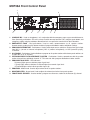
Power Intercom Systems
Models PI35A & SI35A
Installation and Operation Manual
© 2003 Bogen Communications, Inc.
All rights reserved.
Specifications subject to change without notice.
54-5034-01F 1111
Notice
Every effort was made to ensure that the information in this
guide was complete and accurate at the time of printing.
However, information is subject to change.
Important Safety Information
WARNING: To Reduce The Risk of Fire Or Electric Shock,
Do Not Expose This Apparatus To Rain Or Moisture.
Always follow these basic safety precautions when
installing and using the unit:
1.
2.
3.
4.
Read these instructions.
Keep these instructions.
Heed all warnings.
Follow all instructions.
5. Do not use this apparatus near water. The apparatus
shall not be exposed to dripping or splashing and no
objects filled with liquids, such as vases, shall be
placed on the apparatus.
6. Clean only with dry cloth.
7. DO NOT block any ventilation openings. Install in
accordance with the manufacturerʼs instructions.
8. Do not install near any heat sources such as radiators,
heat registers, stoves, or other apparatus (including
amplifiers) that produce heat.
9. Do not defeat the safety purpose of the polarized or
grounding-type plug. A polarized plug has two blades
with one wider than the other. A grounding-type plug
has two blades and a third grounding prong. The wide
blade, or the third prong, are provided for your safety.
If the provided plug does not fit into your outlet, consult
an electrician for replacement of the obsolete outlet.
10. Protect the power cord from being walked on or
pinched, particularly at plugs, convenience receptacles, and the point where they exit from the apparatus.
11. Only use attachments/accessories specified by the
manufacturer.
12. Unplug this apparatus during lightning storms or when
unused for long periods of time.
13. Refer all servicing to qualified service personnel.
Servicing is required when the apparatus has been
damaged in any way, such as power supply cord or
plug is damaged, liquid has been spilled or objects
have fallen into the apparatus, the apparatus has been
exposed to rain or moisture, does not operate normally, or has been dropped.
IMPORTANT
CAUTION
RISK OF ELECTRIC SHOCK
DO NOT OPEN
CAUTION: TO PREVENT THE RISK OF ELECTRIC
SHOCK, DO NOT REMOVE ANY FRONT/BACK
COVERS OR PANELS. NO USER-SERVICEABLE
PARTS INSIDE.
REFER SERVICING TO QUALIFIED PERSONNEL.
Contents
Unpacking . . . . . . . . . . . . . . . . . . . . . . . . . . . . . . . . . . . . . . . . . . . . . . . . . . . . . . . . . . . . .2
Wiring & Grounding Precautions . . . . . . . . . . . . . . . . . . . . . . . . . . . . . . . . . . . . . . . . . .2
Auxiliary Power Receptacle . . . . . . . . . . . . . . . . . . . . . . . . . . . . . . . . . . . . . . . . . . . . . .2
Maintenance & Service . . . . . . . . . . . . . . . . . . . . . . . . . . . . . . . . . . . . . . . . . . . . . . . . . .2
Introduction . . . . . . . . . . . . . . . . . . . . . . . . . . . . . . . . . . . . . . . . . . . . . . . . . . . . . . . . . . .3
Description . . . . . . . . . . . . . . . . . . . . . . . . . . . . . . . . . . . . . . . . . . . . . . . . . . . . . . . . . .3
Features . . . . . . . . . . . . . . . . . . . . . . . . . . . . . . . . . . . . . . . . . . . . . . . . . . . . . . . . . . .3
MCP35A Front Control Panel . . . . . . . . . . . . . . . . . . . . . . . . . . . . . . . . . . . . . . . . . . .4
MCP35A Rear Control Panel . . . . . . . . . . . . . . . . . . . . . . . . . . . . . . . . . . . . . . . . . . .5
SBA225 Speaker Selector Front Panel . . . . . . . . . . . . . . . . . . . . . . . . . . . . . . . . . . . .6
Basic System Operation . . . . . . . . . . . . . . . . . . . . . . . . . . . . . . . . . . . . . . . . . . . . . . . . .7
Communicating With a Selected Speaker . . . . . . . . . . . . . . . . . . . . . . . . . . . . . . . . . .7
Distributing Audio to Rooms . . . . . . . . . . . . . . . . . . . . . . . . . . . . . . . . . . . . . . . . . . . .7
Adjusting Program Level to Rooms . . . . . . . . . . . . . . . . . . . . . . . . . . . . . . . . . . . . . . .7
To Make an All-Rooms Announcement . . . . . . . . . . . . . . . . . . . . . . . . . . . . . . . . . . . .7
To Make an Emergency Announcement . . . . . . . . . . . . . . . . . . . . . . . . . . . . . . . . . . .7
Basic System Hook-Up . . . . . . . . . . . . . . . . . . . . . . . . . . . . . . . . . . . . . . . . . . . . . . . . . .8
4-Wire Speaker Connections to the SBA225 . . . . . . . . . . . . . . . . . . . . . . . . . . . . . . .8
Call-In Switches . . . . . . . . . . . . . . . . . . . . . . . . . . . . . . . . . . . . . . . . . . . . . . . . . . . . . .9
Voice Call-In Feature . . . . . . . . . . . . . . . . . . . . . . . . . . . . . . . . . . . . . . . . . . . . . . . . . .9
Voice Call-In Wiring . . . . . . . . . . . . . . . . . . . . . . . . . . . . . . . . . . . . . . . . . . . . . . . . . . .9
Speakers and Speaker Wiring . . . . . . . . . . . . . . . . . . . . . . . . . . . . . . . . . . . . . . . . .10
Time Tones . . . . . . . . . . . . . . . . . . . . . . . . . . . . . . . . . . . . . . . . . . . . . . . . . . . . . . . .10
Advanced Hook-Ups . . . . . . . . . . . . . . . . . . . . . . . . . . . . . . . . . . . . . . . . . . . . . . . . . . .11
External Emergency Mic . . . . . . . . . . . . . . . . . . . . . . . . . . . . . . . . . . . . . . . . . . . . . .11
Emergency Telco Page . . . . . . . . . . . . . . . . . . . . . . . . . . . . . . . . . . . . . . . . . . . . . . .11
External Booster Amp . . . . . . . . . . . . . . . . . . . . . . . . . . . . . . . . . . . . . . . . . . . . . . . .12
TWK351 Wire Converter . . . . . . . . . . . . . . . . . . . . . . . . . . . . . . . . . . . . . . . . . . . . . .13
SCR25A Call-In Module . . . . . . . . . . . . . . . . . . . . . . . . . . . . . . . . . . . . . . . . . . . . . .14
CA17 Call-In Switch . . . . . . . . . . . . . . . . . . . . . . . . . . . . . . . . . . . . . . . . . . . . . . . . .14
SI35A Model Option Enhancements . . . . . . . . . . . . . . . . . . . . . . . . . . . . . . . . . . . . . .15
Special Adjustments . . . . . . . . . . . . . . . . . . . . . . . . . . . . . . . . . . . . . . . . . . . . . . . . . . .16
Gain Adjustments . . . . . . . . . . . . . . . . . . . . . . . . . . . . . . . . . . . . . . . . . . . . . . . . . . .16
Internal Jumper Selections . . . . . . . . . . . . . . . . . . . . . . . . . . . . . . . . . . . . . . . . . . . .17
Phantom Power . . . . . . . . . . . . . . . . . . . . . . . . . . . . . . . . . . . . . . . . . . . . . . . . .17
Telco Page/MIC 2 . . . . . . . . . . . . . . . . . . . . . . . . . . . . . . . . . . . . . . . . . . . . . . . .17
MIC 1/Console Mic . . . . . . . . . . . . . . . . . . . . . . . . . . . . . . . . . . . . . . . . . . . . . . .17
Privacy Tone Defeat . . . . . . . . . . . . . . . . . . . . . . . . . . . . . . . . . . . . . . . . . . . . . .17
Troubleshooting Guide . . . . . . . . . . . . . . . . . . . . . . . . . . . . . . . . . . . . . . . . . . . . . . . . .18
System Specifications . . . . . . . . . . . . . . . . . . . . . . . . . . . . . . . . . . . . . . . . . . . . . . . . . .19
Accessory Equipment . . . . . . . . . . . . . . . . . . . . . . . . . . . . . . . . . . . . . . . . . . . . . . . . . .19
1
Unpacking
Your Bogen equipment was carefully checked before leaving the factory; inspect the shipping container and unit
closely for improper handling. If the unit has been damaged, make an immediate claim to the distributor from whom
it was purchased. If the unit was shipped directly to you, save all shipping materials and notify the carrier immediately and place a claim.
Wiring and Grounding Precautions
The MCP35A master control panel of the PI and SI products operates from a 120V 60 Hz AC source and consumes approximately 100 watts. The AC line cord is terminated in a three-prong plug, and should be plugged into
an appropriate three-wire grounded outlet. It is important that the unit be properly grounded. Three-prong pigtail
adapters may be used only if the ground lug is properly grounded.
Auxiliary Power Receptacle
An 840-watt, three-wire grounded outlet is provided on the rear panel for power auxiliary equipment. Equipment
connected to this outlet will be grounded only if the MCP35A control panel is properly grounded.
Maintenance & Service
Caution: There are no user-serviceable parts within the unit. Have all internal servicing performed by a qualified
technician. The warranty will become void if repairs are made by other than the Bogen Service Department or an
authorized service agency.
Our Applications Engineering Department is available to help you troubleshoot problems with your Bogen equipment.
Engineers are available from 8:30AM to 8:00PM Eastern Standard Time. Phone 201-934-8500, extension 2242.
Service can be obtained from our factory service department. No merchandise may be returned for repair without
prior written authorization. Please contact our factory service department at 1-800-999-2809 for a RA number. Only
merchandise specified in the return authorization form can be returned to obtain warranty or non-warranty repair.
When shipping your unit, pack your system well using the original shipping carton or a similar container and filler
material to prevent damage in transit. Send the unit fully insured and prepaid via UPS or other responsible carrier.
2
Introduction
Description
Bogen Models PI35A and SI35A are 25-station intercom systems (SI35A is expandable to 75 stations).
They can provide facilities with two-way communication, emergency paging, time tones and background
music or other audio program material to speaker-equipped locations.
Both systems consist of a master control panel (Bogen model MCP35A) and a 25-station room selector
panel (Bogen model SBA225) assembled into an attractive wood grain cabinet. Up to 2 more room selector panels can be purchased separately and added by the installer into the SI35A product (PI35A is not
expandable).
A number of options are available for the SI/PI35A to accommodate various user demands and wiring conditions. These include a CD Player and AM/FM Receiver, room call-in switches, call-in adapter modules for
existing older call-in switches, 2-wire call-in adapters, and various styles of transformer-coupled speakers.
Features
•
•
•
•
•
•
•
Cost-effective communications for 25 rooms
SI35A is expandable to 75 rooms (in increments of 25)
Instant Emergency and All-Rooms Announcements
Remote Emergency Page capability
20-watt intercom
35-watt program channel
Provisions for time signaling, telco, and voice call-in
3
MCP35A Front Control Panel
1
2
9
3
4
5
6
7
8
1. CONSOLE MIC - Used as microphone 1 or in conjunction with the emergency page or press-to-talk/release-tolisten (intercom) push-buttons. This mic is always used for two-way intercom calls, using the green button, and
emergency paging using the red button. No external mic can replace the console mic for these functions.
2. EMERGENCY PAGE - Red push-button. Used to make announcements to all speaker stations.
Announcements made using this button override all program distribution and/or switchbank settings.
3. PROGRAM DISTRIBUTION - Push-buttons. Used to make input source selections. Choose from or mix input
from MIC 1 (console or external microphone), MIC 2 (external microphone), or AUX (tuner/CD player),
as desired.
4. ALL ROOMS - Push-button. Used to distribute a program to all speaker stations with selector panel switches set
to either the “A” or “O” channel.
5. INTERCOM PRESS-TO-TALK/RELEASE TO LISTEN - Push-button. Used to communicate with the speaker
station selected from switchbank channel “C”. This does not affect program distribution to other stations.
6. PROGRAM TALK LEVEL - LED indicators.
N (normal) lights green to indicate proper signal level.
P (peak) lights amber to indicate occasional higher than normal signal level.
O (overload) lights red to indicate possible signal clip.
7. PROGRAM - Amber knob. Used to adjust volume level to speaker stations.
8. MONITOR/LISTEN - Green knob. Used to adjust the volume level to the front panel speaker.
9. FRONT PANEL SPEAKER - Used to monitor a program or to listen to a station via the intercom (C) channel.
4
MCP35A Rear Control Panel
9
10
8
7
6
5
4
11
3
2
12
1
13
1. MIC 1 - Connections for an external mic (MIC 1). When the PROGRAM DISTRIBUTION button MIC 1 is
pressed, the microphone connected here becomes active. As shipped from the factory, a link is installed
between the HI and CONS MIC terminals. This makes the CONSOLE MIC act as MIC 1. When the link is
removed, an external microphone can be connected to act as MIC 1 and the CONSOLE MIC will no longer be
active when the MIC 1 button is pressed.
Note: The CONSOLE MIC is always used when the EMERGENCY PAGE button is pressed and when using
the green INTERCOM PUSH-TO-TALK button (the user cannot change this). The external mic must be a lowimpedance balanced mic (phantom power is also available for condenser mics).
2. MIC 2 - Connections for an external mic (MIC 2). When the PROGRAM DISTRIBUTION button MIC 2 is
pressed, the microphone connected here becomes active. The external mic must be a low-impedance balanced mic (phantom power is also available for condenser mics).
3. VOICE CALL-IN - Allows retro fitting to older voice call-in systems with call-in switches connected in parallel.
When a call-in switch is activated, an intercom channel is opened to the MCP35A control panel speaker so
that the caller can announce verbally which room is calling. Systems that use this style of call-in will not see
an annunciator light on the SBA225 room selector panel.
4. AUX - A high-impedance unbalanced input for auxiliary music sources. This input only becomes active when the
PROGRAM DISTRIBUTION AUX button is pressed.
5. TELCO PAGE - Shorting the TELCO PAGE terminal to GND activates a page from either MIC 2 or the TELCO
INPUT (selected by an internal jumper).
6. TIME CLOCK - Shorting the TIME CLOCK terminal to GND produces a tone signal in all speakers.
7. LINE OUT - Provides an input signal that can be connected to the input of an external booster amp. Works in
conjunction with the 25V BAL INPUT to allow replacement of the MCP35A control panelʼs built-in program
amplifier with a higher power amplifier.
8. SWITCHBANK CONNECTOR - SBA225 switchbank is connected to the MCP35A panel through this connector.
9. AUX POWER - An AC power outlet for auxiliary equipment.
10. 12V POWER TERMINALS - Chassis, ground, +12V DC supply, 750mA for powering up to 3 SCR25A modules.
11. 25V BAL INPUT - The output of an external booster amp is connected at this 1/4” stereo phone jack. Works
in conjunction with the LINE OUT connector (see #7 above).
12. INPUT GAIN - Input level adjustments for all input sources.
13. TELCO PAGE - Alternate input for MIC 2 allows connection of Bogen model WMT1A for providing a 600-ohm
balanced telephone input.
5
SBA225 Speaker Selector Front Panel
1
3
2
1. ROOM SELECTOR SWITCH - Position of the room switch controls the type of audio program material
delivered to the room speaker.
2. CALL ANNUNCIATORS - Lights to indicate a room has placed an intercom request from a call switch.
3. PROGRAM BUSES - A room speaker can be turned off or connected to one of two audio buses.
The Program A bus allows continuous audio to play into the room from an audio source selected on the
MCP35A control panel. The Intercom C bus allows two-way intercom communication from any room whose
selector switch is placed in this position.
6
Basic System Operation
Communicating With a Selected Speaker
Use the following steps to talk and listen to a room that has its switch set to the “C” (down) position.
1. Place the switch of the room that you wish to talk and listen to in the “C” (down) position.
2. Make sure the PROGRAM DISTRIBUTION button MIC 1 is in the out position; if not, push it to pop it out.
3. Press and hold the green PRESS-TO-TALK switch and speak into the CONSOLE MIC (upper left corner).
4. Release the button to listen to the reply. To adjust the volume, use the green MONITOR/LISTEN knob.
Distributing Audio to Rooms
To send audio to rooms continuously, do the following:
1. Set the switches for all the rooms that are to receive the audio into the “A” (up) position.
2. Select the source of the audio by pushing in one or more of the PROGRAM DISTRIBUTION buttons (MIC1,
MIC 2, or AUX). To turn off the audio source, push the button again so that it pops out. If more than one
audio source is selected, the audio from each source will be mixed together.
Note: Make sure that the MIC 1 button is turned off (popped out) before making an intercom announcement. Otherwise the intercom announcement will not only be heard in the desired stations set to “C” but
also in all the rooms set to “A”.
3. To disconnect the audio from a room, simply set the room switch to the “O” (center) position.
Adjusting Program Level to Rooms
While the audio is playing, observe the three PROGRAM TALK LEVEL lights (N, P, and O). The green “N” light
should be lit continuously with the yellow “P” light turning on occasionally. This indicates that the audio level to the
rooms is good. If the red “O” light turns on, it indicates that the volume level going to the room speakers is set too
high. Use the orange program knob to turn the volume down to an acceptable level.
To Make an All-Rooms Announcement
To distribute audio to all rooms that have room selector switches in “A” or “O” positions:
1. Select source using MIC 1, MIC 2, or AUX button.
2. Press the ALL ROOMS button.
To Make an Emergency Announcement
To make an emergency page announcement to all rooms, regardless of switch settings or program source selections, do the following:
1. Press the EMERGENCY PAGE push-button and speak into the CONSOLE MIC.
2. To release the emergency page, push the emergency page button again.
7
Basic System Hook-Up
4-Wire Speaker Connections to the SBA225
4-wire speaker connections (3-conductor + shield) is recommended for all new installations. The figure below
shows the connection to the back of the SBA225 when using a 4-wire system.
Note: You must use Bogen connectors for this connection. There are different connectors available for different
wire gauges. Refer to the list below to determine the correct connector model number.
Connector Kit Numbers:
Use Bogen Connector Kit Model No. 2518 for 18 Ga. Wire
Use Bogen Connector Kit Model No. 2520 for 20 Ga. Wire
Use Bogen Connector Kit Model No. 2522 for 22 Ga. Wire
Note: For speaker-only applications, do not connect the shield to ground at the speaker end (leave it floating).
8
Call-In Switches
Two call-in switches, CA10A and CA11A, are recommended for use with the SI and PI. The CA10A is a momentary push switch that has circuitry to light the annunciator light on the SBA225 room selector panel. The CA11A
has the same capability as the CA10A and includes a privacy lock-out position that inhibits the MCP35A control
panel from listening through the room speaker (it does not interfere with the ability to call the station from the
MCP35A). The wiring of the call switches is shown below.
CA10A Wiring Schematic
CA11A Wiring Schematic (with Privacy)
Voice Call-In Feature
Voice call-in is not recommended for new installations. Pre-existing intercom systems may already have call-in
switches that are wired in parallel with all the other call-in switches. In this instance, the MCP35A voice call-in feature can be used. With this style of operation a room must press the call-in switch and speak into the room speaker. The built-in speaker in the MCP35A will monitor this call so that people near the control panel will hear it.
Typically the caller will say what room the call is being made from. The room selector switch for that room can then
be set for a two-way intercom conversation.
Voice Call-In Wiring
Contact the Bogen Application Engineering Department for information regarding this type of application.
9
Speakers and Speaker Wiring
The MCP35A control panel of the SI and PI products is designed to use 25-volt distributed speakers. These speakers
have line-matching transformers with various power level taps. 8-ohm speakers or speakers without line-matching
transformers cannot be used with the SI and PI products.
Distributed speakers can be tapped at various power levels and this is determined by which wire from the speakerʼs
transformer is used for connection. The user must determine which power tap gives acceptable volume in a given
location. However, it is best to tap the speakers at the lowest acceptable power tap in order to ensure that enough
speakers can be connected to the system without overloading the system amplifier.
The chart below shows the wire colors and power taps for the T725 transformers.
T725
Leads
25V
Black
COM
Brown
4
Red
2
Orange
1
Yellow
1/2
Green
1/4
Blue
1/8
Violet
Grey
White
Caution: Do not attempt to connect a 25V speaker directly to the MCP35A, using GND as one of the connecting
points. This could seriously damage the MCP35A because the unit uses a balanced output when connected to the
speakerʼs lines.
The MCP35A control panel of the PI and SI contains an internal amplifier with 35W power handling capability.
Therefore, the combined power of all the system speakers cannot exceed 35W. To determine the required power
that the system amplifier must handle, add up all the power taps selected for all the speakers in the system. This
is the total system power requirement. If the total of the speaker power taps is too high for the system to handle,
it may be necessary to tap the speakers at the next lowest setting in order to keep from overloading the amplifier.
In many instances, the required speaker tap setting will be either 1/4 or 1/2 watt (you should also factor in 20%
additional power loss through wires, transformers, etc. as a safety margin). The MCP35Aʼs 35-watt amplifier
should provide sufficient power for most applications.
If the systemʼs power requirements are greater than 35 watts and cannot be lowered, it may be necessary to use
an external booster amp. The booster amp replaces the internal amplifier of the MCP35A. Booster amp connections are described on page 12.
Time Tones
A tone signal sounds through all speakers when the clock terminal is grounded through a closure from a master
clock. Reference call out #6 on page 5.
10
Advanced Hook-Ups
External Emergency Mic
It is possible to use a microphone (Model MBS1000A) with a contact closure to make an emergency announcement. The TELCO terminal on the back of the MCP35A control panel can be used to remotely trigger an emergency page on the system. Whenever the TELCO terminal is shorted to the GND terminal, the MIC 2 input will
become active and send audio to all rooms regardless of switch settings. The figure below shows the required
wiring.
Note: Jumper J3 on the MCP35A printed circuit board must be set to the MIC2 position (this is the factory default
setting). See the Special Adjustments section for jumper information.
Emergency Telco Page
Emergency pages can be triggered by devices other than a microphone. To use a source other than a mic, it is
necessary to change the setting of a jumper inside the MCP35A control panel. See the Special Adjustments
section for more information on the jumper change. Below are emergency telco page hook ups for various types
of interfaces.
The Bogen model WMT1A can be used to convert the TELCO PAGE input to a transformer-balanced, 600-ohm
input for telephone paging applications.
Note: Jumper J3 on the MCP35A printed circuit board must be set to the TELCO position. See the Special
Adjustments section for jumper information.
11
The Bogen model TAMB2 Telephone Interface Module can be used to make a remote page through the telephone
system.
PAGE
OUT
PT PR G/S
CONTACT
CLOSURES
NO C NC
Note: Jumper J3 on the MCP35A printed circuit board must be set to the TELCO position. See the Special
Adjustments section for jumper information.
External Booster Amp
An external booster amplifier (Bogen Model BPA60) can be connected when the application requires more than
35 watts. Using an external amplifier disconnects the internal 35W amp of the MCP35A. To install, connect a RCA
cable from the MCP35A LINE OUT jack to the Hi-Z input jack on the rear panel of the BPA60 amplifier. Connect
another cable from the 25V output terminals of the booster amplifier to a 1/4” stereo phono plug wired as shown
in the figure below. Insert this into the jack labeled 25V BAL INPUT on the MCP35A.
12
TWK351 Wire Converter
The model TWK351 is an adapter used in instances where there is existing 3-wire (2-conductor + shield) room
wiring. The TWK351 cannot be used with the SCR25A module. If 3-wire operation using the TWK351 wire converter is desired, CA10A call switches must be used (CA11A Call-In switches will not work in this application).
To install the TWK351, simply insert it between the 9-pin connector labeled TO SWITCHBANK on the rear panel
of the MCP35A and the 9-pin control cable on the first SBA225 panel. Only one TWK351 is required per system.
S
S
A
G
13
SCR25A Call-In Module
The SCR25A module can be added to allow the annunciator indicators to light from a simple SPST call-in switch
(Bogen model CA17). All call-in switches must go back to the SI or PI on separate lines. It will not allow annunciator illumination from parallel connected call-in switches described in the Voice call-in section. The SCR25A
module simply pushes onto the connectors on the back of the SBA225.
The figure below illustrates the connections to the rear of the SCR25A module.
Jumper Settings (see screened drawing on the SCR25A board).
1. Ensure that jumpers J1 - J25 are positioned to the left (toggle position) as shown.
2. Ensure jumper J26 is positioned towards the pin side (Multi-Graphic position) of the SCR25A module.
CA17 Call-In Switch
The CA17 call-in switch is a SPST call-in switch. It must be used with the SCR25A module in order to light the
call annunciators on the SBA225 room selector panel.
The wiring of the CA17 is shown in the drawing above.
14
SI35A Model Option Enhancements
The SI35A has provisions to add up to 2 additional SBA225 switchbanks. Simply remove the blank panels and
replace with a switchbank. Make connections as shown in the diagram below.
An auxiliary music source, such as the Bogen CDR1 CD Player and AM/FM Receiver or DST1 AM/FM Digital Tuner
can also be added to the SI35A. Install the component in the appropriate rack panel and make audio connections to
the MCP35A AUX input. Use the auxiliary power outlet on the MCP35A to power the auxiliary equipment.
Note: Mounting a radio in the cabinet will limit the number of SBA225 panels that can be installed to two because
of the physical size of the cabinet. Mounting the music source outside the cabinet will still allow for three SBA225
panels.
All components may be rearranged in the cabinet to suit the preferences of the user.
CD Player
Tuner
15
Special Adjustments
Gain Adjustments
Screwdriver-adjustable INPUT GAIN controls are located on the rear panel for MIC 1, MIC 2, AUX, TEL PAGE,
TALK and LISTEN. Set the controls so that signal clipping cannot occur. Proceed as follows:
1. Apply input(s) to the desired channel(s).
2. Set the corresponding front panel control(s) to maximum.
3. Adjust the appropriate Input Gain control (looking at the rear panel, turn clockwise to increase or
counterclockwise to decrease gain) so that the red (overload) LED lights; then turn counterclockwise
only until the LED is extinguished.
Warning: High voltages are present within the MCP35A. The unit should not be operated without covers in place.
Internal controls are provided to set the level of emergency page volume, privacy tone volume, and time tone volume. These controls are factory set; under normal circumstances, no further adjustment is required. If adjustment
is needed, unplug the MCP35A and remove it from the enclosure. Remove the top cover and make an approximate adjustment. Replace the top cover and plug the unit back in. Test if the new set volume is acceptable.
Repeat procedure if necessary.
16
Internal Jumper Selections
Internal jumpers are provided for phantom power (MIC1/MIC2), Telco Page/MIC 2 input selection, monitor speaker muting, and privacy tone defeat.
Warning: High voltages are present within the MCP35A. The unit should not be operated without covers in place.
To change jumpers, unplug the MCP35A and remove it from the enclosure. Remove the top cover and place the
jumper in the desired position. Replace the top cover and plug the unit back in.
Phantom Power
To enable phantom power for MIC 1, place J1 in the ON position.
To enable phantom power for MIC 2, place J2 in the ON position
Telco Page/MIC 2
Jumper J3 selects the TELCO PAGE input jack or the MIC 2 input terminals for the telephone page function. Place
the jumper in the MIC 2 position when using the MIC 2 terminals for emergency paging applications using a
microphone. Place the jumper in the TELCO position when using the TELCO PAGE input for paging applications.
MIC 1/Console Mic
1. Locate and loosen the two screws securing the jumper link on the rear chassis terminal strip connecting
MIC 1 HI terminal to the CONS MIC terminal.
2. Move the link away from the CONS MIC terminal.
3. Connect a balanced or unbalanced low-impedance microphone to the MIC 1 terminals. Connect the
cable shield to the GND terminal.
4. Move the shunt on J4 to the OFF position to disable the monitor speaker muting feature when the MIC 1
push-button is selected.
Note: J1 should be in the OFF position when the console mic is connected to the MIC 1 input.
Privacy Tone Defeat
Shunt J5 enables/disables the supervisory tone feature. Move the shunt to the OFF position to disable the supervisory tone.
Note: When the privacy tone is disabled, a short 1 second audio interruption will be noticed every 15 seconds
when intercom communication is in progress.
17
Troubleshooting Guide
MCP35A Troubleshooting Procedure
If a problem exists on the MCP35A, certain steps should be taken to find the problem. This test relates to the
Program Amplifier (All-Call or Emergency). The first indication of a problem will appear on the three level indicators
at the front of the unit. They are green, yellow, and red.
If there is no problem, the green, yellow and/or the red LED should flicker whenever audio is present, depending
on the signal strength. A problem is indicated when the red LED does not flicker no matter what level the program
control is set to.
To find the problem, follow this simple procedure:
1. Disconnect the switchbank(s), SBA225, from the MCP35A and depress the emergency button. While
speaking into the built-in microphone, adjust the Program Level Control and check the level indicators as
described above. If all three indicators can be made to light depending on the output level control setting,
then the MCP35A is okay.
2. Connect only the first switchbank (if more than one is being used). With the speaker load still connected,
check the level indicators again.
3. If the MCP35A LEDʼs still indicate a problem when connected to the switchbank, each speaker location on
that switchbank being tested should be removed one at a time, until the level indicators show a normal
output. The speaker and cable associated with that location should then be checked.
4. Follow the same procedure, connecting each successive switchbank until the troublesome SBA225 panel
or speaker load is found.
5. If the MCP35A is tested without the switchbank, and the three LEDʼs do not ʻlightʼ indicating full output,
then the 35-watt program amplifier of the MCP35A may be defective. Contact the Bogen Applications
Engineering Department for assistance.
If it appears that there is no intercom communication between the unit and a speaker station, the 20-watt intercom
amplifier inside the MCP35A may be defective. Contact the Bogen Applications Engineering Department for assistance.
Caution: Do not attempt to connect a 25V speaker directly to the MCP35A using GND as one of the connecting
points. This could seriously damage the MCP35A because the unit uses a balanced output when connected to the
speaker lines.
18
System Specifications
Rated Output:
Frequency Response:
Distortion:
Inputs:
Output:
Phantom Power:
Input Sensitivity:
(for rated output)
Controls:
Tone Specifications:
Power Requirements:
Dimensions:
Cabinet:
Panels:
Product Weight:
Operating Temp.:
Program – 35 WRMS
Intercom – 20 WRMS
Program – +1, -3 dB from 80 Hz to 15 kHz
Intercom – Shaped for maximum intelligibility
Less than 1% at rated power and bandwidth
Two Lo-Z balanced MIC: Hi-Z unbalanced AUX; Telco Page; 25V Booster
25V Balanced line, Line Out to Booster
15V DC
Program – MIC Input: 300μV balanced Lo-Z; AUX: 100mV unbalanced Hi-Z
Telco Page: 100mV unbalanced Hi-Z; Intercom – Listen Mode: 300μV
balanced Lo-Z (Console MIC: 1mV unbalanced Lo-Z)
Front Panel – Program Selection: MIC 1, MIC 2, AUX; Level: Monitor/
Listen, Program; Distribution: All Rooms, Emergency, Press To Talk;
Indicators: Program Talk/ Level LED
Rear Panel – Input Gain: MIC 1, MIC 2, AUX, Telco Page, Talk, Listen
Internal – Gain: Emergency Page, Supervisory Tone, Time Tone
Enable/Disable: MIC 1/Console MIC; MIC 2/Telco Page, Phantom Power,
Supervisory Tone, MIC 1/Monitor Mute
Time Tone – 750 Hz
Supervisory Tone – Repeating, 500 Hz
Call-in Tone – Repeating; oscillates between 500 Hz and 750 Hz (Switching Freq., 16 Hz)
120V AC, 60 Hz, 100W maximum
PI35A: 20-1/2" W x 8-1/2" H x 11" D (with sloped top)
SI35A: 20-1/2" W x 12" H x 11" D (with sloped top)
Simulated wood grain finish
Black with color-coded lines and instructions for Intercom, Program, Emergency Page
PI35A: 24 lb.; SI35A: 29 lb.
0-130° F
Accessory Equipment:
CDR1 – CD player and AM/FM Receiver
SCR25A – Call-in module (for switches w/o SCR)
SBA225 – Three-Channel (Program A, Off 0, Intercom C), 25-Station Switchbank
WMT1A – Line-matching transformer for telephone paging
TAMB2 – Telephone access module for telephone paging
DDU250, MBS1000A – Desktop paging microphones
CA10A, CA11A, CA17 – Call-in switches (2-pos., 3-pos., and push-button, respectively)
TWK351 – 2-Wire call-in adapter kit
DST1 – Digital Tuner
BPA60 – Power Amplifier
S86T725PG8W 25/70V – Ceiling Speaker
WBS8T725 25/70V – Wall Baffle Speaker
2518, 2520, 2522 – Connector Kits (18-, 20-, and 22-gauge respectively)
TL156 – Insertion Tool for connector kits
19
Notes
20
Notes
21
Limited Warranty; Exclusion of Certain Damages
The Bogen PI35A & SI35A Power Intercom Systems are warranted to be free from defects in material and workmanship for two (2) years
from the date of sale to the original purchaser. Any part of the product covered by this warranty that, with normal installation and use,
becomes defective (as confirmed by Bogen upon inspection) during the applicable warranty period, will be repaired or replaced by Bogen,
at Bogen’s option, provided the product is shipped insured and prepaid to: Bogen Factory Service Department, 50 Spring Street, Ramsey,
NJ 07446, USA. Repaired or replacement product will be returned to you freight prepaid. This warranty does not extend to any of our products that have been subjected to abuse, misuse, improper storage, neglect, accident, improper installation or have been modified or repaired
or altered in any manner whatsoever, or where the serial number or date code has been removed or defaced.
THE FOREGOING LIMITED WARRANTY IS BOGEN’S SOLE AND EXCLUSIVE WARRANTY AND THE PURCHASER’S SOLE AND
EXCLUSIVE REMEDY. BOGEN MAKES NO OTHER WARRANTIES OF ANY KIND, EITHER EXPRESS OR IMPLIED, AND ALL IMPLIED
WARRANTIES OF MERCHANTABILITY OR FITNESS FOR A PARTICULAR PURPOSE ARE HEREBY DISCLAIMED AND EXCLUDED
TO THE MAXIMUM EXTENT ALLOWABLE BY LAW. Bogen's liability arising out of the manufacture, sale or supplying of products or their
use or disposition, whether based upon warranty, contract, tort or otherwise, shall be limited to the price of the product. IN NO EVENT SHALL
BOGEN BE LIABLE FOR SPECIAL, INCIDENTAL OR CONSEQUENTIAL DAMAGES (INCLUDING, BUT NOT LIMITED TO, LOSS OF
PROFITS, LOSS OF DATA OR LOSS OF USE DAMAGES) ARISING OUT OF THE MANUFACTURE, SALE OR SUPPLYING OF PRODUCTS, EVEN IF BOGEN HAS BEEN ADVISED OF THE POSSIBILITY OF SUCH DAMAGES OR LOSSES. Some States do not allow the
exclusion or limitation of incidental or consequential damages, so the above limitation or exclusion may not apply to you. This warranty gives
you specific legal rights, and you may also have other rights which vary from State to State.
Products that are out of warranty will also be repaired by the Bogen Factory Service Department – same address as above or call 201-9348500. The parts and labor involved in these repairs are warranted for 90 days when repaired by the Bogen Factory Service Department. All
shipping charges in addition to parts and labor charges will be at the owner's expense. All returns require a Return Authorization number.
For most efficient warranty or repair service, please include a description of the failure.
12/2008
50 Spring Street, Ramsey, NJ 07446, U.S.A.
Tel. 201-934-8500 • Fax: 201-934-9832
www.bogen.com