1
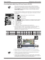
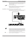
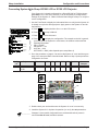
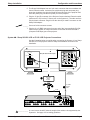
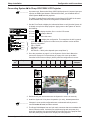
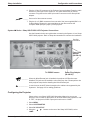
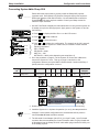
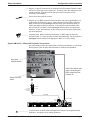
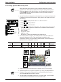
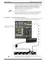
Sharp Installation
Configuration and Connections
xi
SYSTEM 4xi
PROJECTOR COMMUNICATIONS KIT
ATTENTION!
PLEASE READ THIS DOCUMENT FOR IMPORTANT
INSTALLATION INSTRUCTIONS
THIS KIT HAS BEEN SHIPPED WITH THE FOLLOWING COMPONENTS:
Kit Type: SHARP
Included Communications Adapter(s):
Quantity
1
1
Part Number
26-426-01
26-467-01
Description
ADP, SHARP IR
ADP, UNV, “A”
THE TABLE BELOW LISTS THE POSSIBLE CONFIGURATION(S) AND CORRESPONDING
COMMUNICATIONS ADAPTER(S) FOR YOUR PROJECTOR MANUFACTURER’S VARIOUS
MODELS. PLEASE NOTE THAT YOUR SWITCHER HAS BEEN CONFIGURED AS
INDICATED BY THE “✔” IN THE “CONFIG AS” COLUMN. IF YOUR PROJECTOR MODEL
DIFFERS FROM THIS CONFIGURATION, YOU MUST RECONFIGURE YOUR SWITCHER
WITH THE CORRECT SETTINGS.
PLEASE REFER TO THE FOLLOWING PAGES FOR COMPLETE CONFIGURATION AND
SIGNAL CONNECTION INSTRUCTIONS.
THIS SWITCHER HAS BEEN CONFIGURED FOR:
CONFIG
AS
✔
MODEL
1
SW1
2 3
4
SHARP XG SERIES (RS-232)
SW2 SW3 SW4 SW5 SW6 PROJ
COMM
CABLE ADAPTER
XG-E1200U
off on off on
0
0
3
F
0
J15
26-426-01
XG-1000/E1100
off on off on
0
0
3
F
0
J15
26-426-01
XG (RS-232)
off on off on
0
0
9
F
0
J15
26-467-01
XG-NV6/NV2U/NV5
off on off on
0
0
9
F
1
J15
26-467-01
XG-NV3
off on off on
0
0
9
F
0
J15
26-467-01
XG-P10XU
off on off on
0
0
9
F
1
J15
26-467-01
PG-C30XU
off on off on
0
0
9
F
1
J15
26-467-01
XG-P20XU
off on off on
0
0
9
F
0
J15
26-467-01
Extron • System 4xi Switcher Series • User’s Manual • P/N 68-409-02 Rev. C
Page 1
Sharp Installation
Configuration and Connections
xi to Sharp XG Series Projector (RS-232)
Connecting System 4xi
Please follow the steps below to properly install the Sharp LCD projector.
________ Important note! Some Sharp LCD projector Computer Input ports require an
RGB signal between VGA and XGA rates. You will not be able to install the
System 4LQxi with some projector models. Consult your Sharp manual for
maximum input resolution.
1. Use the Front Panel to display the Information Menu to verify that the System 4xi
is already set up for the Sharp projector. Apply power to the System 4xi and do
the following:
to display the MENU SELECT on the LCD screen.
a. Press
b. Press
[System 4NE model and software
version displayed here]
(See note.)
c. Press
to step to Menu 8.
to select this menu.
}
d. Press
or
to display the configuration. The example to the left is general,
yours will show the System 4xi model name, the software version and the
following information:
PRJ = SHRP232
PRJ BAUD = 9600
UNIT No. = 000
HST BAUD = 9600 (value depends upon setup Menu 3)
(See note.)
(See note.)
(See note.)
(Note: Information depends on
System 4NE setup.)
or
2. Go to the procedure on page 2-3 of the System 4xi Series User’s Manual to
remove the System 4xi cover. Then go to page 2-4 and refer to the
configuration below to set up the Main Controller board. Continue with Step 3
(below) when the configuration is correct.
Config
as
✔
Projector
SW1: 1-2-3-4 SW2
Sharp XG (RS-232) off-on-off-on
0
SW3
0
SW4 SW5
9
F
SW6 Prj Cable
0
Comm
Adapter
J15
26-467-01
SW3
SW5
SW2
J15
SW1
1
2
3
SW4
4
ON
3. Double-check your work and be sure the System 4xi cover is on securely.
4. Install the System 4xi in its place of operation (i.e. rack), but not powered on.
________ Changes in some switch configurations are not detected until the power is
removed at the AC cord, and then restored.
5. The Universal Comm Adapter (26-467-01) is a 9-pin D male - 9-pin D female
connector that accommodates the Comm Extension cable. Plug the female end
of this adapter into the PC Control port of the Sharp projector.
Extron • System 4xi Switcher Series • User’s Manual • P/N 68-409-02 Rev. C
Page 2
Sharp Installation
Configuration and Connections
6. Plug the 15-pin HD connector of the Projector Communications Extension cable
into the PJ Comm port on the System 4xi. The other end of the cable has a 9-pin
female connector. Plug this end into the 9-pin male D connector on the
Universal Comm adapter.
______ Secure all of the connector screws.
7. Plug the (4 or 5) BNC connectors from one end of the (user-supplied) BNC-4 or
5 cable onto the System 4xi output and those on the other end into the
Computer RGB Input port (Input 2) of the projector.
xi Series – Sharp XG Series Projector Connections (RS-232 control)
System 4xi
Use the illustration below as a guide when connecting the System 4xi to a Sharp
Series projector. Refer to Sharp documentation to continue the installation.
Universal
CommAdapter
26-467-01
VIDEO INPUT
S-VIDEO
9-Pin Male
9-Pin Female
AUDIO INPUT
PC CONTROL
MOUSE
FOR PC98
WIRED
REMOTE
VIDEO
L
R
COMPUTER RGB
INPUT 1
VIDEO OUTPUT
AUDIO OUTPUT
OUTPUT
L
FILTER
INPUT 2
R
G
B
H
V
ON
COMPUTER
AUDIO IN
R
DC5V OUTPUT
MAX CURRENT 1A
-
+
OFF
RGBHV 5 BNC
15-Pin
Male
INPUT 1
H/HV
R/C
INPUT 2
V
G/Y
AUDIO
B
H/HV
R/C
INPUT 3
V
G/Y
AUDIO
B
H/HV
R/C
INPUT 4
V
G/Y
AUDIO
B
H/HV
R/C
OUTPUT
V
G/Y
AUDIO
B
PJ COMM
RS 232
H/HV
V
R/C
AUDIO
G/Y
B
________ When RS-232 control of the projector is used, the projector’s IR remote can be
used. However, because the projector’s IR remote does not communicate with
the System 4xi switcher, the projector and switcher can become out-of-sync if
the projector’s IR remote is used to change the projector’s input, picture mute or
power settings. Should this occur, press the power, mute or channel buttons on
the switcher to allow the projector and switcher to resynchronize.
____________ In a rack mount, do NOT allow the weight of the cables to be supported by the
System 4xi. See page 2-5 for cabling guidelines.
Extron • System 4xi Switcher Series • User’s Manual • P/N 68-409-02 Rev. C
Page 3
Sharp Installation
Configuration and Connections
xi to Sharp XG1000 LCD or E1100 LCD Projector
Connecting System 4xi
If the System 4xi is already configured for a Sharp XG1000 or E1100 projector,
go to step 4. If it is not set up correctly, it will be necessary to change switch
settings on the System 4xi ’s Main Controller Board. Begin at Step 1 to verify the
correct configuration.
1. Use the Front Panel to display the Information Menu to verify that the System 4xi
is already set up for the Sharp projector. Apply power to the System 4xi and do
the following:
a. Press
b. Press
[System 4NE model and software
version displayed here]
(See note.)
(See note.)
(See note.)
(See note.)
(Note: Information depends on
System 4NE setup.)
to display the MENU SELECT on the LCD screen.
or
c. Press
to step to Menu 8.
to select this menu.
}
or
to display the configuration. The example to the left is general,
d. Press
yours will show the System 4xi model name, the software version and the
following information:
PRJ = SHARP
PRJ BAUD = n/a
UNIT No. = 000
HST BAUD = 9600 (value depends upon setup Menu 3)
2. Go to the procedure on page 2-3 to remove the System 4xi cover and then go to
page 2-4 to set up the Main Controller board. Return to Step 3 (below) when the
configuration is correct.
Config
as
Projector
SW1: 1-2-3-4 SW2
Sharp XG1000 and off-on-off-on
E1100
0
SW3
0
SW4 SW5
3
F
SW6 Prj Cable
0
Comm
Adapter
J15
26-426-01
SW3
SW5
SW2
J15
SW1
1
2
3
SW4
4
ON
3. Double-check your work and be sure the System 4xi cover is on securely.
4. Install the System 4xi in its place of operation (i.e. rack), but not powered on.
__________ Changes in some switch configurations are not detected until the power is
removed at the AC cord, and then restored.
Extron • System 4xi Switcher Series • User’s Manual • P/N 68-409-02 Rev. C
Page 4
Sharp Installation
Configuration and Connections
5. The Sharp COM Adapter has one 9-pin male connector that accommodates the
Comm Extension cable. It also has one miniphone plug and one power plug.
Insert the miniphone plug into the Wired Remote input jack of the projector and
insert the power plug into the Aux power port of the projector.
6. Plug the 15-pin HD connector of the Projector Communications Extension cable
(shown as CC 50') into the PJ Comm port on the System 4xi. The other end has
a 9-pin female connector. Plug this into the other 9-pin male D connector on the
Sharp COM adapter.
______ Secure all of the connector screws.
7. Plug the (4 or 5) BNC connectors from one end of the (user-supplied) SY-VGA
cable onto the System 4xi output and those on the other end into the RGB 2
(Computer RGB Input) port of the projector.
xi - Sharp XG1000 LCD or E1100 LCD Projector Connections
System 4xi
Use the illustration below as a guide when connecting the System 4xi to a Sharp
XG1000 or E1100 projector. Refer to Sharp documentation to continue the
installation.
Filter
ON
ANALOG
OFF
Sharp XG-1000 or E1100 Projector
DIGITAL
INPUT
1
AUDIO
R
L
VIDEO
S-VIDEO
WIRED
REMOTE
INPUT
2
COMPUTER RGB INPUT
COMPUTER RGB OUTPUT
RGB INPUT
15-Pin
AUDIO
DC12V
OUTPUT
MAX CURRENT
200mA
C-SYNC
OUTPUT
R
G
15.75kHz/15.625kHz
B
-
red
cable
+
ANALOG RGB
Sharp COM
Adapter
26-426-01
9-Pin
4 or 5 BNC
SY-VGA
Cable
CC 50'
____________ In a rack mount, do NOT allow the weight of the cables to be supported by the
System 4xi. See page 2-5 for cabling guidelines.
Extron • System 4xi Switcher Series • User’s Manual • P/N 68-409-02 Rev. C
Page 5
Sharp Installation
Configuration and Connections
xi to Sharp XG-E1200U LCD Projector
Connecting System 4xi
__________ Important note! Because the Sharp XG-E1200U projector’s Computer Input port
requires an RGB signal between VGA and XGA rates, you will not be able to
install System 4LQxi with this projector.
The Main Controller Board configuration for the Sharp XG-E1200U is the same
as the standard Sharp XG-series configuration as shown below.
1. Use the Front Panel to display the Information Menu to verify that the System 4xi
is already set up for the Sharp projector. Apply power to the System 4xi and do
the following:
a. Press
b. Press
[System 4NE model and software
version displayed here]
(See note.)
(See note.)
(See note.)
(See note.)
(Note: Information depends on
System 4NE setup.)
c. Press
to display the MENU SELECT on the LCD screen.
or
to step to Menu 8.
to select this menu.
}
d. Press
or
to display the configuration. The example to the left is general,
yours will show the System 4xi model name, the software version and the
following information:
PRJ = SHARP
PRJ BAUD = n/a
UNIT No. = 000
HST BAUD = 9600 (value depends upon setup Menu 3)
2. Go to the procedure on page 2-3 of the System 4 Series User’s Manual to
remove the System 4xi cover and then go to page 2-4 to set up the Main
Controller board. Return to Step 3 (below) when the configuration is correct.
Config
as
Projector
SW1: 1-2-3-4 SW2 SW3
Sharp XG-E1200U off-on-off-on
0
0
SW4 SW5 SW6 Prj Cable
3
F
0
Comm
Adapter
J15
26-426-01
SW3
SW5
SW2
J15
SW1
1
2
3
SW4
4
ON
3. Double-check your work and be sure the System 4xi cover is on securely.
4. Install the System 4xi in its place of operation (i.e. rack), but not powered on.
__________ Changes in some switch configurations are not detected until the power is
removed at the AC cord, and then restored.
5. The Sharp COM Adapter has one 9-pin male connector that accommodates the
Comm Extension cable. It also has one miniphone plug and one power plug.
Insert the miniphone plug into the Wired Remote input jack of the projector and
insert the power plug into the DC5V Output port of the projector.
Extron • System 4xi Switcher Series • User’s Manual • P/N 68-409-02 Rev. C
Page 6
Sharp Installation
Configuration and Connections
6. Plug the 15-pin HD connector of the Projector Communications Extension cable
into the PJ Comm port on the System 4. The other end has a 9-pin female
connector. Plug this into the other 9-pin male D connector on the Sharp COM
adapter.
______ Secure all of the connector screws.
7. Plug the (4 or 5) BNC connectors from one end of the (user-supplied) BNC-4 or
5 cable onto the System 4xi output and those on the other end into the
Computer RGB Input port (Input 2) of the projector.
xi Series - Sharp XG-E1200U LCD Projector Connections
System 4xi
Use the illustration below as a guide when connecting the System 4xi to a Sharp
XG-E1200U projector. Refer to Sharp documentation to continue the installation.
See first
note below
➸
From COM
Adapter
(26-426-01)
}
To RGBHV source
Power Plug Adapter
(26-446-01)
________ When the Wired Remote jack is installed, the projector’s IR Receivers are
disabled. This jack can be installed or removed at any time. Please perform the
basic projector setup before installing the Wired Remote jack.
____________ In a rack mount, do NOT allow the weight of the cables to be supported by the
System 4xi. See page 2-5 for cabling guidelines.
Configuring the Projector
Please refer to your Sharp XG-E1200U Operations Manual to set up your
projector. Also, in order for the System 4xi to know whether the projector is “ON”
or “OFF”, the projector’s 5VDC output jack must be set to “LAMP”.
1. Select MENU.
2. Select SYSTEM SETUP.
▲
4. Using the
LAMP.
▲
3. Select DC 5V OUTPUT.
buttons on the rear of the Sharp XG-E1200U, select
Extron • System 4xi Switcher Series • User’s Manual • P/N 68-409-02 Rev. C
Page 7
Sharp Installation
Configuration and Connections
xi to Sharp NV6
Connecting System 4xi
Please follow the steps below to properly install the Sharp NV6 projector.
________ Important note! Some Sharp LCD projector Computer Input ports require an
RGB signal between VGA and XGA rates. You will not be able to install the
System 4LQxi with some projector models. Consult your Sharp manual for
maximum input resolution.
1. Use the Front Panel to display the Information Menu to verify that the System 4xi
is already set up for the Sharp projector. Apply power to the System 4xi and do
the following:
to display the MENU SELECT on the LCD screen.
a. Press
b. Press
[System 4NE model and software
version displayed here]
(See note.)
c. Press
to step to Menu 8.
to select this menu.
}
d. Press
or
to display the configuration. The example to the left is general,
yours will show the System 4xi model name, the software version and the
following information:
PRJ = SHARP
PRJ BAUD = 9600
UNIT No. = 000
HST BAUD = 9600 (value depends upon setup Menu 3)
(See note.)
(See note.)
(See note.)
(Note: Information depends on
System 4NE setup.)
or
2. Go to the procedure on page 2-3 of the System 4xi Series User’s Manual to
remove the System 4xi cover. Then go to page 2-4 and refer to the
configuration below to set up the Main Controller board. Continue with Step 3
(below) when the configuration is correct.
Config
as
Projector
Sharp NV6
SW1: 1-2-3-4 SW2
off-on-off-on
0
SW3
0
SW4 SW5
9
F
SW6 Prj Cable
1
Comm
Adapter
J15
26-467-01
SW3
SW5
SW2
J15
SW1
1
2
3
SW4
4
ON
3. Double-check your work and be sure the System 4xi cover is on securely.
4. Install the System 4xi in its place of operation (i.e. rack), but not powered on.
________ Changes in some switch configurations are not detected until the power is
removed at the AC cord, and then restored.
5. The Universal Comm Adapter (26-467-01) is a 9-pin D male - 9-pin D female
connector that accommodates the Comm Extension cable. Plug the female end
of this adapter into the Sharp RS-232C cable which plugs into the RS-232C port
of the Sharp projector.
Extron • System 4xi Switcher Series • User’s Manual • P/N 68-409-02 Rev. C
Page 8
Sharp Installation
Configuration and Connections
6. Plug the 15-pin HD connector of the Projector Communications Extension cable
into the PJ Comm port on the System 4xi. The other end of the cable has a 9-pin
female connector. Plug this end into the 9-pin male D connector on the
Universal Comm adapter.
______ Secure all of the connector screws.
7. Plug the (4 or 5) BNC connectors from one end of the (user-supplied) BNC-4 or
5 cable onto the System 4xi output. If the projector end of the BNC cable has
BNC connectors, set the input type selector switch (see illustration below) to
“BNC” and attach the BNC connectors. If the projector end of the BNC cable
has a 15-pin HD connector, set the input type selector switch (see illustration
below) to “15-pin” and attach the 15-pin connector to the Computer RGB Input 1
port of the projector.
________ Important note! When connecting the System 4xi BNC output to either the
projector’s BNC or 15-pin input (but not both simultaneously), set the projector’s
input type selector switch to the appropriate “BNC” or “15-pin” setting.
xi Series – Sharp NV6 Projector Connections
System 4xi
Use the illustration below as a guide when connecting the System 4xi to a Sharp
NV6 projector. Refer to Sharp documentation to continue the installation.
○
○
○
○
○
○
input type
selector switch
○
○
○
○
○
○
○
○
refer to the above note
when connecting the
BNC output from the
System 4xi
○
○
○
○
○
○
○
○
Sharp RS-232C
cable
○
○
9-pin female
Universal
CommAdapter
26-467-01
○
9-pin male
CC cable
RGBHV 5 BNC
15-Pin
Male
INPUT 1
H/HV
R/C
INPUT 2
V
G/Y
AUDIO
B
H/HV
R/C
INPUT 3
V
G/Y
AUDIO
B
H/HV
R/C
INPUT 4
V
G/Y
AUDIO
B
H/HV
R/C
OUTPUT
V
G/Y
AUDIO
B
PJ COMM
RS 232
H/HV
V
R/C
AUDIO
G/Y
B
____________ In a rack mount, do NOT allow the weight of the cables to be supported by the
System 4xi. See page 2-5 for cabling guidelines.
Extron • System 4xi Switcher Series • User’s Manual • P/N 68-409-02 Rev. C
Page 9
Sharp Installation
Configuration and Connections
xi to Sharp NV3
Connecting System 4xi
Please follow the steps below to properly install the Sharp NV3 projector.
________ Important note! Some Sharp LCD projector Computer Input ports require an
RGB signal between VGA and XGA rates. You will not be able to install the
System 4LQxi with some projector models. Consult your Sharp manual for
maximum input resolution.
1. Use the Front Panel to display the Information Menu to verify that the System 4xi
is already set up for the Sharp projector. Apply power to the System 4xi and do
the following:
to display the MENU SELECT on the LCD screen.
a. Press
b. Press
[System 4 model and software
version displayed here]
(See note.)
(See note.)
(See note.)
(See note.)
(Note: Information depends on
System 4 setup.)
or
c. Press
to step to Menu 8.
to select this menu.
}
d. Press
or
to display the configuration. The example to the left is general,
yours will show the System 4xi model name, the software version and the
following information:
PRJ = SHARP
PRJ BAUD = 9600
UNIT No. = 000
HST BAUD = 9600 (value depends upon setup Menu 3)
2. Go to the procedure on page 2-3 of the System 4xi Series User’s Manual to
remove the System 4xi cover. Then go to page 2-4 and refer to the
configuration below to set up the Main Controller board. Continue with Step 3
(below) when the configuration is correct.
Config
as
Projector
Sharp NV3
SW1: 1-2-3-4 SW2
off-on-off-on
SW2
SW3
0
0
SW4 SW5
9
F
SW6 Prj Cable
0
Comm
Adapter
J15
26-467-01
SW3
SW5
SW6
J15
SW1
1
2
3
SW4
4
ON
3. Double-check your work and be sure the System 4xi cover is on securely.
4. Install the System 4xi in its place of operation (i.e. rack), but not powered on.
________ Changes in some switch configurations are not detected until the power is
removed at the AC cord, and then restored.
5. The Universal Comm Adapter (26-467-01) is a 9-pin D male - 9-pin D female
connector that accommodates the Comm Extension cable.
Extron • System 4xi Switcher Series • User’s Manual • P/N 68-409-02 Rev. C
Page 10
Sharp Installation
Configuration and Connections
6. Plug the 15-pin HD connector of the Projector Communications Extension cable
into the PJ Comm port on the System 4xi. The other end of the cable has a 9-pin
female connector. Plug this end into the 9-pin male D connector on the
Universal Comm adapter. Plug the other end of the Comm adapter into the
IOIOI port of the Sharp PC Control adapter, as shown below. The Sharp
adapter plugs into the projector’s PC Control port 1.
______ Secure all of the connector screws.
7. Plug the (4 or 5) BNC connectors from one end of the (user-supplied) BNC-4 or
5 cable onto the System 4xi output. Connect the opposite 15-pin male end of
the BNC cable to the Computer RGB “IN 2” connector of the projector.
xi Series – Sharp NV3 Projector Connections
System 4xi
Use the illustration below as a guide when connecting the System 4xi to a Sharp
NV3 projector. Refer to Sharp documentation to continue the installation.
Sharp PC Control Adapter
plugs in here
○ ○
○ ○
○ ○
○
○
○ ○
○ ○
○ ○
○
○
○ ○
○ ○
Sharp PC Control Adapter
9-pin female
Universal
CommAdapter
26-467-01
9-pin male
CC cable
RGBHV 5 BNC
15-Pin
Male
INPUT 1
H/HV
R/C
INPUT 2
V
G/Y
AUDIO
B
H/HV
R/C
INPUT 3
V
G/Y
AUDIO
B
H/HV
R/C
INPUT 4
V
G/Y
AUDIO
B
H/HV
R/C
OUTPUT
V
G/Y
AUDIO
B
PJ COMM
RS 232
H/HV
V
R/C
AUDIO
G/Y
B
____________ In a rack mount, do NOT allow the weight of the cables to be supported by the
System 4xi. See page 2-5 for cabling guidelines.
Extron • System 4xi Switcher Series • User’s Manual • P/N 68-409-02 Rev. C
Page 11