1
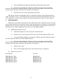
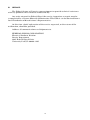
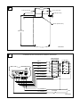
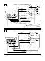
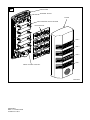
INSTALLATION AND SERVICE INSTRUCTIONS
FOR
SEMISTAT™ DIRECT I/O STATUS INDICATOR
MODEL SCB/SCC
Address all communications and shipments to:
FEDERAL SIGNAL CORPORATION
Electrical Products Division
Service Department
2645 Federal Signal Drive
University Park, IL 60466-3195
INSTALLATION AND SERVICE INSTRUCTIONS
FOR
SEMISTAT™ DIRECT I/O STATUS INDICATOR MODEL SCB/SCC
SAFETY MESSAGE TO INSTALLERS, USERS AND MAINTENANCE PERSONNEL
It is important to follow all instructions shipped with this product. This device is
to be installed by a trained electrician who is thoroughly familiar with the Country
Electric Codes and will follow these guidelines as well as local codes.
The selection of mounting location for the device, its controls and the routing of
the wiring is to be accomplished under the direction of the facilities engineer and the
safety engineer. In addition, listed below are some other important safety instructions
and precautions you should follow:
•
Read and understand all instructions before installing or operating this
equipment.
•
Disconnect unit from the power supply before any installation or
maintenance is performed.
•
After installation, test the device to ensure that it is operating properly.
•
After testing is complete, provide a copy of this instruction sheet to all
operating personnel.
•
Establish a procedure to routinely check the device installation for
integrity and proper operation.
•
The product nameplate, which may contain cautionary or other information of importance to maintenance personnel, should not be obscured in
any way.
Failure to follow all safety precautions and instructions may result in property
damage, serious injury, or death.
I.
INSTALLATION.
A.
Unpacking.
After unpacking the light, examine it for damage that may have occurred in
transit. If the equipment has been damaged, do not attempt to install or operate it. File
a claim immediately with the carrier stating the extent of the damage. Carefully check
all envelopes, shipping labels, shipping labels and tags before removing or destroying
them.
B.
Mounting.
The SemiStat is designed for mounting on a flat horizontal or vertical surface
on machines, cabinets, and control panels. The unit may be mounted with the sounder
grill at the top or bottom of the light windows. Three-high and four-high units have
identical mounting footprints.
-1-
1.
Surface Mounting.
a. Remove the cover by prying the snap-catch loose on either the top
or bottom of the unit.
b. Mark the mounting holes on the surface by the dimensions shown
in figure 1 or directly from the backplane. Also mark the location of the center-wiring
hole.
c.
Drill or punch the mounting holes and wire-entrance hole.
d. Mount the backplane to the mounting surface using the appropriate
user supplied hardware.
e.
Refer to the electrical connections instructions before reinstalling
the cover.
C.
Electrical Connections.
Units are provided with a nine-position screw terminal block to accommodate
field wiring. This unit may be wired for continuous or flashing operation. The switching
may be via dry contact or transistor switching. Transistor switching may be PNP or
NPN type. Refer to the appropriate wiring diagram for instructions. Fusing is to be
supplied by the user.
To avoid electrical shock hazards, do not connect to the supply circuit when
power is applied.
1.
Remove the cover as outlined above if necessary.
2. Route wiring (18-22AWG, 300V) through the center-wiring hole under
the printed circuit board. Feed wires to the terminal block.
3. Strip wires a maximum of 0.25” (6mm) and insert wire into terminal
block. If stranded wire is used, be sure that there are no loose strands outside the
connector that could touch an adjacent lead to cause a short circuit. Tighten the
terminal block screw to a maximum torque of 5 in-lb (.6Nm).
4.
diagrams.
Connect wires according to the desired wiring scheme. Refer to attached
5. If LED module or switch re-configuration is necessary proceed to section
D. Otherwise, reinstall cover taking care not to pinch supply wiring.
D.
LED Module Configuration and Volume Control.
The LED modules may be placed in any position on the printed circuit board.
A white LED module may be purchased separately. To re-configure the LED modules:
1.
Disconnect power to unit to prevent shock hazard.
2.
Remove cover as outlined previously if necessary.
-2-
3.
Lift the LED board upwards off of the PCB mounting headers.
4. Reinsert the module by aligning the box connectors with the PCB
headers and press the module into place. Be sure that the module connectors fully
engage the header pins and that the module is sitting flat.
5.
Reinstall cover and test for proper operation.
The piezo sounder is provided with an adjustable volume control potentiometer
(R14). To adjust, insert a small flat-blade screwdriver into the potentiometer slot and
turn clockwise to increase the volume and counterclockwise to decrease the volume.
II.
MAINTENANCE.
This unit is generally maintenance free. The outer cover and lens may be cleaned
using mild detergent, but remove first to avoid damaging the electronics. Low-pressure
compressed air may be used to clean dust from the printed circuit boards if necessary.
The only serviceable component on the device is the LED modules.
A.
LED Module Replacement.
1.
Disconnect power to unit to prevent shock hazard.
2.
Remove the cover by prying the snap-catch on the bottom of the unit.
3. Grasp the LED module and remove by lifting upwards. The box connectors will separate from the main PCBA headers.
4. Reinsert the module by aligning the box connectors with the PCB
headers and press the module into place. Be sure that the module connectors fully
engage the header pins and that the module is sitting flat.
B.
5.
Replace the cover.
6.
Test unit for proper operation after replacement is complete.
Replacement Parts.
Description
Part No.
LED Module, Red
LED Module, Amber
LED Module, Blue
LED Module, Green
LED Module, White
K2001925A
K2001925A-01
K2001925A-02
K2001925A-03
K2001925A-04
-3-
III.
SERVICE.
The Federal factory will service your equipment or provide technical assistance
with any problems that cannot be handled locally.
Any units returned to Federal Signal for service, inspection, or repair must be
accompanied by a Return Material Authorization. This R.M.A. can be obtained from a
local Distributor or Manufacturer’s Representative.
At this time a brief explanation of the service requested, or the nature of the
malfunction, should be provided.
Address all communications and shipments to:
FEDERAL SIGNAL CORPORATION
Electrical Products Division
Service Department
2645 Federal Signal Drive
University Park, IL 60466-3195
-4-
1
2.91"
(74.0 mm)
1.45" (37.0 mm)
0.17" (4.5 mm)
0.34" (8.5 mm)
0.26" (6.5 mm)
Ø0.47" (Ø12.0 mm)
7.09"
(180.0 mm)
290A4923
2
CONTINUOUS OR FLASHING WITH CONTACT SWITCHING
CONTINUOUS
AND BUZZER
FLASHING
LED 1
LED 2
LED 3
LED 4
+
AL1 (ALARM 1)
AL2 (ALARM 2)
P1 1
J1
2
3
4
AL1 AL2 P2 FC
J2
J3
FC (FLASHING COMMON)
-
P2 (POWER 2)
P1 (POWER 1)
1A FUSE
+
24V
290A4926
3
CONTINUOUS OR FLASHING WITH NPN TRANSISTOR
B
LED 2
NPN
C
B
LED 3
NPN
C
B
LED 4
NPN
C
B
AL1 (ALARM 1)
NPN
C
NPN
C
B
AL2 (ALARM 2)
+
NPN
C
B
LED 1
P1 1
2
3
4
J1
AL1 AL2 P2 FC
E
E
E
E
NPN
C
B
NPN
C
B
NPN
C
B
NPN
C
B
E
E
E
E
E
J3
J2
E
FC (FLASHING COMMON)
-
P2 (POWER 2)
1A FUSE
P1 (POWER 1)
24V
+
290A4927
4
CONTINUOUS OR FLASHING WITH PNP TRANSISTOR
B
LED 2
PNP
C
B
LED 3
PNP
C
B
LED 4
PNP
C
B
AL1 (ALARM 1)
PNP
C
PNP
C
B
AL2 (ALARM 2)
+
PNP
C
B
LED 1
P1 1
J1
2
3
4
AL1 AL2 P2 FC
E
E
E
E
PNP
C
B
PNP
C
B
PNP
C
B
PNP
C
B
E
E
E
E
E
J3
J2
E
FC (FLASHING COMMON)
+
P2 (POWER 2)
P1 (POWER 1)
1A FUSE
-
24V
290A4928
5
BACKPLANE
TERMINAL BLOCK
COVER
MAIN PRINTED CIRCUIT BOARD
LED MODULES
LED 4
LED 3
LED 2
LED 1
PIEZO VOLUME CONTROL
290A4929
2561978A
REV. A Printed 2/04
Printed in U.S.A.