1
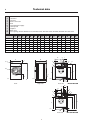
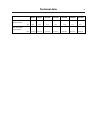
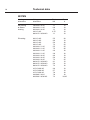
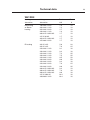
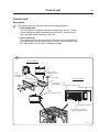
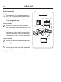
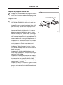
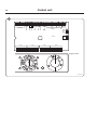
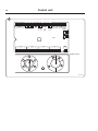
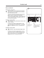
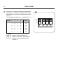
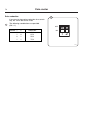
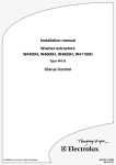
Service Manual W475N, W485N, W4105N, W4130N, W4180N, W4250N, W4330N Classic Control 438 9226-71/EN 07.04 Contents Contents Safety Precautions........................................................................................ 5 Technical data............................................................................................... 7 Machine presentation ................................................................................ 17 Description............................................................................................. 17 Function.................................................................................................. 18 Programme unit...................................................................................... 19 Door lock................................................................................................ 20 Heating................................................................................................... 21 Water connections.................................................................................. 21 Rear control unit..................................................................................... 21 Detergent compartment......................................................................... 22 Drain valve.............................................................................................. 22 Control unit ................................................................................................ 23 Description............................................................................................. 23 Front control unit.................................................................................... 24 Jumpers on program selector card........................................................ 25 Rear control unit..................................................................................... 31 Level control . ............................................................................................. 37 Control and fault tracing . ...................................................................... 37 Water level check .................................................................................. 38 Water level is too high ........................................................................... 38 Thermostat.................................................................................................. 39 Data........................................................................................................ 39 Description ............................................................................................ 39 Repair instructions ................................................................................ 40 Replacing the thermostat ...................................................................... 40 Door and door lock..................................................................................... 41 General................................................................................................... 41 The door lock locks the door ................................................................ 42 The door lock unlocks the door............................................................. 43 Error codes............................................................................................. 44 Reset button........................................................................................... 45 Door lock control inputs/outputs............................................................ 45 Repairs................................................................................................... 48 Emergency opening of door lock .......................................................... 48 Replacing the door lock......................................................................... 49 Motor........................................................................................................... 51 Description............................................................................................. 52 Principle wiring....................................................................................... 53 Motor overload protector....................................................................... 54 Repairs................................................................................................... 55 Motor replacement................................................................................. 55 Adjustments........................................................................................... 57 Drain valve................................................................................................... 59 Function . ............................................................................................... 59 Repairs................................................................................................... 60 Disassembly........................................................................................... 60 Assembling............................................................................................. 61 Contents Detergent compartment.............................................................................. 63 Heating........................................................................................................ 65 Description ............................................................................................ 65 Electric heating....................................................................................... 66 Steam heating........................................................................................ 66 Repairs................................................................................................... 67 Replacing the heating elements............................................................. 67 Coin-meter.................................................................................................. 69 Setting wash price.................................................................................. 69 Programming the current price.............................................................. 71 Price reduction....................................................................................... 72 Regular maintenance ................................................................................. 73 Daily........................................................................................................ 73 Every third month................................................................................... 73 Safety Precautions Safety This machine can only be used with water. Never use dry cleaning agents. Do not allow children to operate the machine. Do not hose down or spray the machine with water. All mechanical and electrical installation must be carried out by qualified personnel. Do not bypass the door locking device. Should the machine malfunction, please report the fault to the technician responsible for the machine. All external equipment which is connected to the machine must be CE/EMC-approved and connected using an approved shielded cable. The manufacturer reserves the right to make changes to design and component specifications. Technical data Technical data W475N W485N W4105N W4130N W4180N W4250N W4330N Innerdrum volume diameter litres mm 75 520 85 520 105 595 130 595 180 650 250330 725 795 Drum speed wash extraction rpm 52 52 49 49 44 44 42 528 528 494 494 471 446 427 4.8/9.3 13 x x 10.7/18 x x 11/23 x x 81 Heating electricity kW steam hot water 2.0/3.0/ 2.0/3.0/5.63.0/6.5/3.0/6.5 5.4/5.6/7.5 5.4/7.5 7.5/10 7.5/10 x x x x x x x x G-factor 81 81 81 81 81 81 kg 130 136 160 175 228 287330 W485N W4105N W4130N W4180N Weight, net Connections W475N Water valves connection W4250N W4330N DN20 DN20 DN20 DN20 DN20 DN20 DN20 BSP 3/4"3/4"3/4"3/4"3/4"3/4"3/4" Rec. water pressure kPa 200-600 200-600 200-600 200-600 200-600 200-600 200-600 Functioning limits for water valve kPa 50-1000 50-1000 50-1000 50-1000 50-1000 50-1000 50-1000 l/min 20 20 20 20 60 60 60 Drain valve outer Ø mm 75 75 75 75 75 75 75 Draining capacity l/min 170 170 170 170 170 170 170 DN15 1/2" DN15 1/2" DN15 1/2" DN15 1/2" DN15 1/2" DN15 1/2" DN15 1/2" Capacity at 300 kPa Steam valve connection BSP Rec. steam pressure kPa 300-600300-600300-600300-600300-600300-600300-600 Functioning limits for steam valve kPa 50-800 50-800 50-800 50-800 50-800 50-800 50-800 Technical data 1 2 3 4 5 6 7 8 9 10 Electrical connection Cold water Hot water Steam connection Drain Liquid detergent supply Control panel Soap box Water reuse Door opening, W475N, W485N: ø310, W4105N: ø365, W4130N: ø395, W4180N, W4250N, W4330N: ø435 A B C D E F G H I K L M N O P R W475N 660 690 1115355 725 825 45 1030 215 1010 130 830385 - 100 210 W485N 660 730 1115355 765 825 45 1030 215 1010 130 830385 - 100 210 W4105N 720 705 1200365 740 910 45 1115 215 1095 130 910 420 - 100 235 910 420 W4130N 720 790 1200365 825 910 45 1115 215 1095 130 - 100 235 W4180N 750 880 1325 435 915 1035 45 1245 130 1225 210 1040325 295 100 225 W4250N 830 955 1410 495 990 1120 45 1330 160 1290 245 1125325325 100 265 W4330N 910 1040 1445 500 1075 1155 45 1365 160 1325 245 1155 280325 100 210 A 8 7 2 N B G I 3 L 4 9 6 1 10 C H K M F 5 D 5281 5282 P 5283 Front R 5 E Rear side Right side 3 N W475N-W4130N O L G I 4 2 9 6 1 F M K H P 5459 5 Rear side R W4180N-W4330N Technical data W475N W485N W4105N W4130N W4180N W4250N W4330N 9.3 9.3 8.7 8.7 7.9 8.3 7.5 1.4±3.5 1.7±4.1 2.8±5.3 Frequency of the dynamic force Hz Max floor load at extraction KN 1.1±2.8 1.2±3.1 2.2±4.73.8±6.0 Technical data 10 W475N Heating alternative Voltage alternative Total kW Fuse A No heating or Steam heating El heating 190-200 V 3 AC 230-240 V 1 AC 200-240 V 3 AC 240 V 3 AC 380-415 V 3/3N AC 200 V 3 AC 230 V 3 AC 230 V 3 AC 230 V 3 AC 230-240 V 1 AC 230-240 V 1 AC 230-240 V 1 AC 230-240 V 1 AC 220-240 V 3 AC 220-240 V 3 AC 220-240 V 3 AC 380-415 V 3/3N AC 380-415 V 3/3N AC 380-415 V 3/3N AC 415 V 3/3N AC 415 V 3/3N AC 415 V 3/3N AC 440/480 V 3 AC 400/230 V 3/3N AC 1.1 0.9 1.1 0.75 1.1 10 10 10 10 10 5.5 3.0 5.3 7.2 5.5 7.5 2.0 2.9 3.0 5.3 7.2 3.1 5.3 7.2 3.3 5.7 7.8 7.8 7.2 20 10 16 25 25 35 16 16 10 16 25 10 10 16 10 10 16 16 16/25 Technical data 11 W485N Heating alternative Voltage alternative No heating or Steam heating El heating 120 V 1 AC 190-200 V 3 AC 208-240 V 1 AC 200-240 V 3 AC 200 V 3 AC 230-240 V 1 AC 230-240 V 1 AC 230-240 V 1 AC 208-240 V 1 AC 230-240 V 1 AC 220-240 V 3 AC 220-240 V 3 AC 208-240 V 3 AC 220-240 V 3 AC Total kW Fuse A 1.3 1.3 1.1 1.3 16 10 10 10 5.5 2.2 3.2 5.5 6.9 7.5 3.1 5.3 6.9 7.2 20 16 16 35 35 35 10 16 25 25 Technical data 12 W4105N Heating alternative Voltage alternative No heating or Steam heating El heating 190-200 V 3 AC 200-240 V 3 AC 380-415 V 3/3N AC 415 V 3N AC 415-480 V 3 AC 400-415 V 3/3N AC 200 V 3 AC 200 V 3 AC 230 V 3 AC 230 V 3 AC 220-240 V 3 AC 220-240 V 3 AC 220-240 V 3 AC 380-415 V 3/3N AC 380-415 V 3/3N AC 380-415 V 3/3N AC 415 V 3/3N AC 415 V 3/3N AC 415 V 3/3N AC 440/480 V 3 AC 400/230 V 3/3N AC 400/230 V 3/3N AC Total kW Fuse A 1.5 1.6 1.6 1.6 1.6 1.6 10 10 10 10 10 10 5.5 7.3 3.1 7.2 3.1 7.2 9.5 3.1 7.2 9.5 3.3 7.8 10.3 10.3 7.2 9.5 20 25 16 25 16 25 35 10 16 16 10 16 16 16 16/25 16/35 Technical data 13 W4130N Heating alternative Voltage alternative heating No or Steam heating heating El 190-200 V 3 AC 208-240 V 1 AC 200-240 V 3 AC 230-240 V 1 AC 380-415 V 3/3N AC 415 V 3N AC 400-415 V 3/3N AC 415-480 V 3 AC 200 V 3 AC 200 V 3 AC 220-240 V 1 AC 230-240 V 1 AC 220-240 V 1 AC 230-240 V 1 AC 220-240 V 1 AC 230-240 V 3 AC 220-240 V 3 AC 220-240 V 3 AC 220-240 V 3 AC 380-415 V 3/3N AC 380-415 V 3/3N AC 380-415 V 3/3N AC 415 V 3/3N AC 440/480 V 3 AC Total kW Fuse A 1.6 1.2 1.7 1.4 1.7 1.7 1.7 1.7 10 10 10 10 10 10 10 10 5.6 7.3 3.1 3.2 7.2 7.5 9.5 9.9 3.2 7.3 9.6 3.2 7.3 9.6 10.4 10.4 20 25 16 16 35 35 50 50 16 25 35 10 16 16 16 16 Technical data 14 W4180N Heating alternative Voltage alternative No heating or Steam heating El heating 190-200 V 3 AC 208-240 V 1 AC 200-240 V 3 AC 400-415/230 V 3/3N AC 380-415 V 3/3N AC 415 V 3N AC 415-480 V 3 AC 200 V 3 AC 220-240 V 1 AC 230 V 3 AC 220-240 V 3 AC 380-415 V 3/3N AC 415 V 3/3N AC 440/480 V 3 AC 400/230 V 3/3N AC Total kW Fuse A 2.1 2.3 2.1 2.1 2.1 2.1 2.1 10 16 10 10 10 10 10 9.5 12.5 12.5 12.5 12.5 13.4 13.5 12.5 35 63 50 50 25 25 20 25/50 Technical data 15 W4250N Heating alternative Voltage alternative heating No or Steam heating heating El 190-200 V 3 AC 208-240 V 1 AC 200-240 V 3 AC 380-415 V 3/3N AC 415-480 V 3 AC 200 V 3 AC 230 V 3 AC 220-240 V 3 AC 380-415 V 3/3N AC 415 V 3/3N AC 440 V 3 AC 480 V 3 AC 400/230 V 3/3N AC Total kW Fuse A 2.8 2.8 2.8 2.8 2.8 10 16 10 10 10 13.2 17.2 17.2 17.2 18.6 18.7 18.7 17.2 50 50 50 35 35 35 25 35/50 Technical data 16 W4330N Heating alternative Voltage alternative heating No or Steam heating heating El 190-200 V 3 AC 200-240 V 3 AC 380-415 V 3/3N AC 415-480 V 3 AC 200 V 3 AC 220-230 V 3 AC 230 V 3 AC 240 V 3 AC 380-400 V 3N AC 415 V 3/3N AC 440V 3 AC 480 V 3 AC 400/230 V 3/3N AC Total kW Fuse A 1.7 1.9 1.7 1.9 10 10 10 10 15.4 19.2 20 20.7 19.2 20.7 21.9 23.7 20 50 63 63 63 35 35 35 35 35/63 Machine presentation Machine presentation 17 1 Description 1 The machines covered in this manual include the following models: Drum volume Model name (litres) 75 W475N 85 W485N 105 W4105N 130 W4130N 180 W4180N 250 W4250N 330 W4330N The machines feature an electromechanical programme unit with fixed washing programmes. The machines are supplied to customer specifications with e.g. electric or steam heating or no heating. The machines are designed for installation in hotels, laundries (such as apartment buildings and coin laundries), factories, hospitals, various institutions, etc. 5203 A Machine presentation 18 Function This section presents a general overview of the functions of the machine. Most functions are then presented in detailed in separate chapters in this service manual. 2 2 Water inlet valves Detergent compartment Motor relays Rear control unit Programme unit Control panel Outer drum Door Door lock Motor Heating elements Frame Drain valve 5916 Machine presentation Programme unit 3 4 The control panel has a rotary switch for selection of fixed machine programmes and a combined start/pause button with rapid advance. 19 3 Programme unit The programme unit controls the water valves, drain valve and heating via the communication card in the rear control unit. This unit can also be connected to send control signals to external units for detergent pumps. The programme unit of the machine is described in detail in section Programme unit. 5916 4 Programme unit A1 Communication card A21 Drain, water, detergent Heating element Water valves Drain valve K21 Voltage supply 5190 Machine presentation 20 Door lock 5 6 5 Door lock control The door lock is an electro-mechanical type with double safety switches. The lock is bi-stable, i.e., it needs to receive an active pulse from the control in order both to lock and unlock the door. A separate printed circuit board, called door lock control, can be fitted onto the programme unit. This board controls locking and unlocking. The card has separate checks for empty drum and stopped drum. Together with the checks built into the programme unit, this guarantees that the door cannot be opened by a mistake. The door lock on the machine is described in detail in section Door and door lock. Door lock 6108 A 6 Door lock control A31 Level guard B2 Programme unit A1 Motor module A107 Door lock A41 M1 Rotation sensor B3 5191 Machine presentation Heating 7 When using electric heating, the water for washing is heated by three heating elements accessible from the front of the machine. 7 21 Rear control unit Main power switch Contactor K21 (heating) The machine can also be fitted with steam heating using a steam valve fitted on the rear of the machine. The heating system of the machine is described in detail in section Heating. Water connections 7 Depending on the machine size and customer specifications, the machine has one, two, three or four inlet valves. This unit also holds eight connectors for external detergent supply. Supply voltage connection Communication card Water connections Rear control unit 7 This box contains the main power switch or a connection block for the input voltage, heating contactor and a communication card with outputs that control the water and drain valves of the machine as well as the heating. There are also connection blocks for connection to e.g., an external detergent supply. The rear electric box of the machines is described in detail in section Control unit. Heating elements 5182, 5916 Machine presentation 22 Detergent compartment 8 The compartment is divided into four for prewash, main wash, rinse and bleaching-agent/liquid detergent. 8 Detergent compartment The detergent compartment of the machine is described in detail in section Detergent compartment. Drain valve 8 This valve is a diaphragm valve that opens and closes by way of the water pressure. The control valve is situated next to the water valves. The drain valve of the machine is described in detail in section Drain valve. Drain valve 5916 Control unit 23 Control unit Description The control unit of the machine consists of the following parts: 1 • Front control unit This unit contains an electro-mechanical programme unit A1, a safety control card for the door lock (door lock control A31), thermostat B1, level switch B2 and 4 and rotary switch S5. • Rear control unit This module contains the main power switch Q1 with a connection for received voltage, the heat contactor K21 and the communication card A21 with outputs for e.g. external detergent supply. 1 Front control unit A31 Door lock controller S5 Rotary switch program selector B1 Thermostat B2 Level switch Rear control unit B4 Level switch wash program Q1 Main power switch A21 Communication card A1 Programme unit K21 Heater contactor K22 Heater contactor (only on larger machines) 5925, 5182, 5916 Control unit 24 Front control unit 2 Programme unit A1 2 Front control unit The programme unit is electromechanical and has up to 10 fixed programmes (depending on program). S5 Rotary switch program selector The programme unit is described in detail in section Programme unit. B2 Level switch Level guard B2 2 Control of the water level and turning of the drum are controlled with a backup guard, to ensure that the door will not open with water in the drum or when the drum rotates. Apart from a level guard on the programme unit card, there is a level guard B2, connected to the door lock control A31. This card controls door locking action as well as the level and drum rpm speed. Level guard B4 2 A31 Door lock controller B1 Thermostat B4 Level switch wash program A1 Programme unit Controls the water level for low and high level in wash programs. Thermostat B1 2 Controls the wash temperature and closes the heating relay or steam valve when selected temperature is reached. Rotary switch S5 Rotary switch for selecting wash program. 5925 Control unit Jumpers on program selector card 3 Jumpers are assembled on the program selector card. These jumpers can be moved or removed to obtain new functions for the wash programs. 25 3 Program selector card Program OG01 4 Jumper on A gives a correct function of valve Y25 (W4180-4330N). Y25 will flush in both pre wash and in main wash. Jumper B gives a correct function of valve Y25 (W475-4130N). Y25 will flush only in pre wash and not main wash. Jumper on C is bleaching function. It is recommended when compartment 4 is used for bleaching agent or if bleaching agent is supplied from a pump unit. There will be a flushing in compartment 4 during 30 seconds, 3.5 minutes after selected temperature is reached. Note! The pump signal, on connection X72:5 will appear 30 seconds before the flushing of compartment 4. Jumper on D is main wash function. It is recommended when compartment 4 is used for main wash detergent or if main wash detergent is supplied from pump. Jumper on F gives a correct function of valve Y12 (W4180-4330N). There are no Y22 valve on these machines. Jumper on G. (W4180-4330N with only cold water inlet). The signal for Y25 (hot inlet) will give cold inlet (Y15) instead. Jumper on H for the machines (W4180-4330N without inlet valve Y35 will give cold inlet (Y15) instead and for the machines (W475-4130N without inlet valve Y35 will give cold inlet (Y11) in compartment 1 instead. Jumper I (no heat). On machines without heating or machines with support heating. The wash program will not stop and wait for the selected temperature. 5471 Control unit 26 4 ��� ���� � � � � � � � � � ��� ��� � � ���� � � � � � � � ���� � � � � � � � ���� � � � ��� ��� ��� ��� ��� ��� ��� ��� ��� ��� ����� � � � � � ���� � � �� � � ���� ���� � � ��������� � � �� � ����� �� ��� � ������ � ����� � ������ � ��� ������ � ������ � ������� � ���� � � � � Program OG01 ��� � �� � �� �� �� �� � �� �� �� �� �� � 6053, 5477 Control unit Program OL02 5 Jumper on A gives correct function of Y25 (W4180-4330N). Y25 will flush in pre-wash and in main wash. Jumper B gives correct function of Y25 (W475-4130N). Y25 will flush in pre wash and not main wash. Jumper on C is bleaching function. It is recommended when compartment 4 is used for bleaching agent or if bleaching agent is supplied from a pump unit. There will be a flushing in compartment 4 during 30 seconds, 3.5 minutes after selected temperature is reached. Note! The pump signal, on connection X72:5 will appear 30 seconds before the flushing of compartment 4. Jumper on D is main wash function. It is recommended when compartment 4 is used for main wash detergent of if main wash detergent is supplied from pump. Jumper on E gives a correct function of valve Y15 (cold water). The valve Y15 will open in main wash (W4180-4330N). Jumper on F gives a correct function of valve Y12 (W4180-4330N). There are no Y22 valve on these machines. Jumper on G. (W4180-4330N with only cold water inlet). The signal for Y25 (hot inlet) will give cold inlet (Y15) instead. Jumper on H for the machines (W4180-4330N) without inlet valve Y35 will give cold inlet (Y15) instead and for the machines (W475- 4130N) without inlet valve Y35 will give cold inlet (Y11) in compartment 1 instead. Jumper I (no heat). On machines without heating or machines with support heating. The wash program will not stop and wait for the selected temperature. Jumper J (short program). If the jumper isn’t connected the agitation time in the wash program will be twice as long. Pre wash will be changed from 3 to 6 minutes, main wash from 6 to 12 minutes and rinsing time from 1 to 2 minutes. 27 Control unit 28 � � ��� � � � �������� ���� � � ���� � � �� � � � ���� � � � � � � � ���� � � � � � � � ���� � � � � � � � ��� ��� � ��� � ��� ��� ��� �� ��� ��� ���� ��� � � � � ��� � �� ��� ��� � �� ��� ��� �� ���� ������ � �� ���� ���� ��� � � ����� � � � ��� ��������� ����� � ������ � ��� 5 � � ���� � � ��������� � � ���� � � Program OL02 ��� � � � � � 6054, 5478 Control unit Program OL03 6 Jumper on A gives correct function of Y25 (W4180-4330N). Y25 will flush in pre-wash and in main wash. Jumper B gives correct function of Y25 (W475-4130N). Y25 will flush only in pre wash and not main wash. Jumper on C is bleaching function. It is recommended when compartment 4 is used for bleaching agent or if bleaching agent is supplied from a pump unit. There will be a flushing in compartment 4 during 30 seconds, 3.5 minutes after selected temperature is reached. Note! The pump signal, on connection X72:5 will appear 30 seconds before the flushing of compartment 4. Jumper on D is main wash function. It is recommended when compartment 4 is used for main wash detergent of if main wash detergent is supplied from pump. Jumper on E gives correct function of valve Y15 (cold water). The valve Y15 will open in main wash (W4180-4330N). Jumper on F gives a correct function of valve Y12 (W4180-4330N. There are no Y22 valve on these machines. 29 Control unit 30 6 � � � � ������� ������� � � ������� ���� �� � � � � � � � � � � ��� ������������� ������ � ������� � ���������� � ���� ����������� � ��������� � � ��� � � � ���� � � � � � � � ���� � � � � � � � ���� � � � � � � � ���� � � � � Program OL03 6055, 5475 Control unit Rear control unit 31 7 Main power switch Q1 7 The main power switch interrupts all received power phases and is placed on the outside of the connection box cover. The cover cannot be removed unless the main power switch is turned to the 0 position. Main power switch Q1 Heating contactor K21 The received voltage supply is connected to the lower screw post of the main power switch, alt. the terminal connection. Heating contactor K21 7 This contactor is only featured on machines with electric heating. It activates the three heating elements at the front, lower part of the outer drum. It is controlled by the programme unit A1 and thermostat B1. Heating contactor K22 7 Voltage supply connector Heating contactor K22 (only larger machines with six heating elements) This contactor is only featured on larger machines. It activates the three heating elements, with a total of four circuits, situated at the front, lower part of the outer drum. It is controlled by the programme unit A1 and thermostat B1. 5182 Control unit 32 Communication card • Fuses F11 and F12 (1.25 A) These protect the received voltage supply for the programme unit and door lock controller. Communication card • Output connection blocks Control signals for connection to external system such as detergent supply. Card No. Function Outputs (110-240V AC) 5182 9 X81 ��� Liquid supply 4 (Bleach) X41 ��� Liquid supply 3 (Softener) X72:5 ��� X72:4 ��� Liquid supply 2 (Main wash) X42 X53 ��� Liquid supply 1 (Pre wash) X72:3 ��� Common X72:2 X43 ��� X72:1 X44 ��� L1 Door locked ��� 0 V Door locked (common) X71:2 X45 ��� X71:1 ��� see Payment system ��� X70 ��� 9 This communication card contains: ��� 8 8 X52 X51 X50 X46 X47 X48 X49 6052 Control unit Option card 10 33 10 The option card is only available on machines with programme OL03. Option card 5182, 5475 34 11 12 Control unit There are some possibilities to alter the standard parameters in the wash programs by moving or adding jumpers on the option card. 11 3 spare jumpers • When adding a jumper on N or M gives warm rinses instead of cold. M shall be used on W475N-W4130N and N on W4180N-W4330N. 5600 12 5601, 5602 Control unit 13 14 15 • When adding a jumper on O there will be no pre-wash in the programs. The timer rapid advances the pre-wash automatically. Remember that "Delicate" is always without pre-wash. 35 13 • When adding a jumper on P there will be two rinses instead of three. The timer rapid advances the first rinse. • If the jumper on Q is removed the main wash will be extended by three minutes to nine minutes instead of six. 5603 14 5604 15 5605 36 16 Control unit • In standard position on R, low level is used in pre-wash, main wash and high level in rinses. If jumper is moved to S it will be high level also in pre-wash and mainwash. 16 5606 Level control Level control 1 2 37 1 The level switch is a pressure sensor controlling two different drum water levels by sensing air pressure in a hose connected to the drum’s bottom. When the water rises in the drum and hose, the air in the hose compresses and, at two preset pressure levels (shut-off levels), two different alternating contacts in the pressure sensor are activated. When the water drains from the drum, the contacts switch back to original position, but now at lower water levels than was required to activate the contacts when the drum was being filled. These levels are called minimum levels. If the water level during washing falls below the minimum level, water will be added until the shut-off level is again reached. Control and fault tracing All level sensors are factory-set for the various machines. As a rule, this setting should not be changed. For that reason, the level controls are sealed with enamel paint. A faulty level switch can not be repaired and should be replaced. The machine guarantee ceases to be valid if the level sensor is tampered with. 1198 Level control 38 Water level check 2 Start the machine and select a standard program. Check low water level for prewash and main wash according to the illustration. Advance the program using the START button and check high water level for rinsing. 2 Low level High level 21 22 24 11 12 14 Water level is too high • Check that the hose connecting the level switch and the drain valve is not obstructed. When necessary and when the machine is empty of water, clean the hose by disconnecting it from the level switch and blowing air through it. • Check the hose for holes which can be caused by the hose rubbing against the pulley. • Overfilling can also be caused by burnt contacts in the level switch. If this is the case, replace the level switch. 1417 Thermostat Thermostat 39 1 Data Range off-on approx. 4°C X123 1 Max. temperature for sensor 150°C Sensor medium 6 Liquid Description 1 The thermostat monitors the temperature while the machine carries out a program. The heating element contactor is controlled using open and closed contacts. The thermostat sensor is located at the lowest point of the outer drum to the left of the heating element. A liquid-filled cable (capillary tube) runs from the sensor to the thermostat, located in the automatic control unit. The water temperature controls the liquid expansion and thereby the activation of the various thermostat contacts. 1453 Temperature selection (contact selection) (90°C, 60°C, 40°C or 30°C) is controlled by the programmer and the program selector. ���� ��° �� �� ���� � � �� �� � ��° �� �� �� � ��° �� �� �� � ��° �� �� �� � 5977 Thermostat 40 Repair instructions All thermostats are factory-set for the various machines. As a rule, this setting should not be changed. For that reason, the thermostats are sealed with enamel paint. The machine guarantee ceases to be valid if the thermostat is tampered with. Replacing the thermostat • Remove the front panel and pull out the thermostat sensor. • Undo the capillary tube strapping and replace the thermostat. Install the new capillary tube in the same way as the old one. Door and door lock Door and door lock 41 8 General The door locks consists of the following: 1 Emergency opening button • Door lock A111, which contains - An actuator that locks the door lock and also has two built-in micro switches, S4a and S4b. The actuator is bi-stable, i.e., it has two stable positions: locked door and unlocked door. The actuator must receive a pulse to lock and unlock the door lock. S4a and S4b are both closed when the door is locked. - A micro switch S3 that is closed when the door is closed. - An emergency opening arm/emergency opening button that can be used to open the door lock in an emergency. 2 • Door lock controller A31 situated in the front control unit of the machine. This card controls the door lock function and supervises whether the drum is empty and not turning. It locks and unlocks the door lock when the programme unit requests door locking or unlocking. X96 (to door lock control A31) X30 (to programme unit A1) 6112 9 Door lock controller A31 5184, 5916 Door and door lock 42 The door lock locks the door 3 When the door is closed (closed door lock switch S3), the programme unit may request door locking by applying a voltage of 110-240 V on the door lock controller A31 input X92. The following check is made by the A31 card prior to locking of the door: • No water in drum - input X93 from level guard B2 is closed = 0 V • Motor not engaged - input X94 from motor control A107 open = 5 V • Drum not turning - no pulses on input X95 from rotation sensor B3. When the above conditions are met, the card A31 outputs a closing pulse on output X96 to the door lock actuator/coil, which then locks the door. The micro switches S4a and S4b in the actuator/door lock are closed when the door is locked. These micro switches feed voltage to: • The output switches on the programme unit. The switches control the machine’s drain and water valves as well as heater switch-on. • Interlock signal enables motor operation. Programme operation is now possible. 3 Door lock control A31 X93 Level guard B2 X95 X94 Programme unit A1 X92 X31 X96 X27 X24 X304 Motor X302 module A107 X30 Door lock A41 M1 Rotation sensor B3 5191 B Door and door lock The door lock unlocks the door 4 43 4 The programme unit requests door unlocking by applying 0 V on input X92 of the door lock controller. The following check is made prior to unlocking of the door: • No water in drum - input X93 from level guard B2 is closed = 0 V Door lock control A31 X93 X95 X94 Programme unit A1 X92 X31 X96 X27 X24 X30 • Motor not engaged - input X94 from motor controller A107 open = 5 V • Drum not turning - no pulses on input X95 from rotation sensor B3. When the above conditions are met, the door lock controller outputs an opening pulse on output 96 to the door lock actuator/coil, which then unlocks the door. Micro switches S4a and S4b now interrupt the relays/switches. The drain, water valves, heater and motor cannot now be switched on. Level guard B2 X304 Motor X302 module A107 Door lock A41 M1 Rotation sensor B3 5191 B Door and door lock 44 Error codes 5 5 The door lock control has three LEDs that show whether the door lock operates normally or whether an error has been detected. During normal operation, the LEDs blink when the drum is not turning and are off when the drum rotates. In case of an error, the three LEDs will show the error condition according to the table below. If an error disappears, the error code condition disappears. If the error is still present at the programme end, the error is automatically cleared after 5 minutes and the door is unlocked. A LEDs B C ● ● No error. The drum is not turning (LEDs blinking) ❍ ❍ ❍ No error. The drum is rotating Error state ● ● ❍ Level guard B2 indicates water in drum when the door lock is open (input X93 not closed). ❍ ● ● Motor control indicates that motor is operating when door lock is open (input X94 not open). ● ❍ ❍ No signal from rotation sensor B3 (frequency input X95 < 0.4 Hz) in spite of the motor control indicating motor operation (input X94 open). ❍ ● ❍ No signal from motor control (input X94 not open) in spite of rotation sensor B3 indicating motor operation (frequency input X95 > 0.4 Hz). ● ❍ ● Error in drive circuits for door lock (output X96) or error in door lock/cable harness for the door lock. ❍ ❍ ● Internal error in the door lock control. ❍ = no lit, ● = lit LEDs B C Normal operation ● LEDs A B C A Reset button 5184 Door and door lock Reset button 5 6 The door lock control features a reset button used to reset the programme routines stored in the computer. When pressed, any error codes are erased. Door lock control inputs/outputs 6 45 X90: AC 110-240 V AC feed X91: Transfer of voltage supply Feeds the voltage to programme unit A1. X92: Input from programme unit: Lock door Prior to the door lock control locking the door (output X96), a check is made for any water left in the drum (input X93 closed) and whether the drum is not rotating (input X94 open). 200240 V Voltage supply to A1 Level guard B2 X90 2 X91 Programme unit requests door locking 0 V: Programme unit requests door opening 1 2 X93 1 2 X94 1 2 B3 X95 1 2 1 2 X92 Input voltage X96 Function 110-240 V AC: Door lock control A31 1 X31 1 3 Motor relays Programme unit A1 5193 Door and door lock 46 7 X93: Input from level guard If the input indicates “Water in drum” when the door is not locked, the door cannot be locked. The LEDs then show the error code ● ● ❍. Input voltage Function X93 5 V DC: Water in drum (level guard open) 0 V: Drum empty (level guard closed) X94: Input from motor control 7 200240 V Voltage supply to A1 Level guard B2 If the input indicates “Motor operating”, the door cannot be locked. The LEDs then show the error code ❍ ● ●. The input signal from X94 is compared with the signal from the rotation sensor B3 (input X95). Door lock control A31 1 2 X91 1 2 X93 1 2 X94 1 2 B3 X95 If the motor signal is operating, but the rotation sensor does not provide a signal, the error code ● ❍ ❍ is shown. If the rotation sensor indicates motor rotation when there is no motor signal, the error code ❍ ● ❍ is shown. X90 1 2 1 2 X92 X31 1 3 Motor relays Programme unit A1 Input voltage Function X94 5 V DC: Motor not operating (input closed) 0 V: Motor operating (input open) 5193 Door and door lock 8 X95: Input from rotation sensor on motor shaft 9 When the motor is operating, a pulse train is applied on the input. 47 8 Rotation sensor B3 X95 Input Function Pin 1: DC 4-10 V feed Pin 2: 0V Pin 3: DC 5 V pulse input Door lock control A31 1 2 3 Unlocks + Locks - X96: Output to door lock Locks the door lock when the following conditions are met: 1 + 2 X96 • DC 110-240 V AC on input X92 (programme unit requests door locking). • DC 0 V on input X93 (no water in drum). • DC +5 V on input X94 (motor not operating). Y80 • No pulses on input X95 (drum not rotating). Door lock A41 • No error code present. Unlocks the door lock when the following conditions are met: 5194 • DC 0 V on input X92 (programme unit requests door unlocking). • DC 0 V on input X93 (no water in drum). 9 • DC +5 V on input X94 (motor not activated). • No pulses on input X95 (drum not rotating). • No error code present. Voltage Function 17 - 31 V DC, + on pin 1, - on pin 2 Unlocks the door 17 - 31 V DC - on pin 1, + on pin 2 Locks the door X96 X95 5184 Door and door lock 48 Repairs 10 Repair work on the machine should only be done by specially trained personnel. Emergency opening of door lock 10 1. Take down power from the machine by turning the main power switch to the 0 position. 2. Remove the front cover or top cover. When replacing the door lock, it is recommended to remove the front cover. 3. Pull the emergency opening arm to the side. This retracts the spring-loaded locking pin and the door lock opens. Alt. Press down the emergency opening button. 4. Reset the emergency opening correctly. 5369, 6111 Door and door lock Replacing the door lock 1. Take down power from the machine by turning the main power switch to the 0 position. 2. Remove the front cover alt. side pole. 3. Remove the door (two screws in each hinge). 4. Remove the front panel. 5. Remove the door lock (three holding screws). 6. Verify the strap positions on the cable for the lock. Cut the necessary straps to undo the cables leading to the lock. 7. Undo the connectors. 8. Replace the door lock. 9. Reconnect the new (door) lock. 10. Assemble in reverse order. 11. Strap the cables for the lock according to the notes made in step 6. 49 50 Motor Motor DANGER Be careful when measuring capacitors and filter. 51 Motor 52 Description 1 The motor is fitted in a bridge carrier under the outer drum. It drives the washing drum using a drive belt. 1 The motor is controlled by contactors. The motor winding is protected against overloads using a thermal overheating protector that is automatically reset. The motor is connected directly to the motor module via a cable with quick connectors. Motor Rotation sensor B3 5467, 5465 2 Programme unit A1 Rotation control card A31 X94 X24 X27 X26 X95 B3 X97 Thermal protection Motor Contactors A107 1 or 3-phase 5975 Motor 53 Principle wiring 3 Single phase Wash speed (18-pole) K1 3 4 1 2 K2 3 4 Extract speed (2-pole) 1 2 3 4 K4 1 2 Black Aux Main Black Blue C1-2 21 22 K4 White Blue 21 White C3-6 A 22 A Only machines with start switch Note! Some machines may hav overcurrent protection. This is not shown here. C3-6 5973 Three phase 5 6 3 4 1 2 K1 5 6 3 4 5 6 1 2 K2 Black Black Blue Blue White White 3 4 1 2 K4 5974 Note! Some motors are possible to change from Y to D-connection to accomodate different voltages. Motor 54 Motor overload protector 4 4 The motor is equipped with one or more thermal overload protectors. The protectors are connected in series and will trip at a temperature of 150 ± 5°C. A burned out motor can be re-wound. Some single-phase machines are also equipped with a manual resettable overload protector mounted on the extract relay in the motor module. This overload protector protects the motor during the start-up of the extraction. 0304 Motor Repairs 55 5 Main power switch Repair work on the machine should only be done by specially trained personnel. Motor replacement Disassembly 5 1. Take down power from the machine by turning the main power switch to the 0 position. 2. Remove the rear cover. 3. Undo the bracket for the drain hose connector from the lower rear piece, then remove the rear cover. 6 4. Undo the ground connection from the motor. 5. Remove the drive belt by pulling the belt towards you while rotating the drum by hand. 6. Undo the motor cable from motor. 7. Undo and remove the motor mounting bolts. 8. Lift out the motor. 5916 6 Rotation sensor B3 5465 Motor 56 Assembly 1. Fit the new motor without locking the mounting bolts. 2. Fit the drive belt and adjust the belt tension with the tensioner on one side of the motor. Se section Adjustments - Drive belt tension for details. 3. Connect the new motor to the cable and use straps to secure the cable. 4. Connect the motor cable to the motor. 5. Fit the lower rear piece and secure the drain hose connection with screws. 6. Fit the upper rear piece. 7. Connect the voltage supply and verify that the motor operates normally. Motor Adjustments 57 7 Drive belt tension The drive belt is pre-tensioned upon delivery from the factory. 7 The drive belt tension should be as follows: Model Force A Post tensioning B New belt C (N) (mm) (mm) W475N35 W485N35 W4105N 40 W4130N 40 W4180N 60 W4250N 68 W4330N 45 8 8 9 8 8 9 8 8 6 8 7 7 7 7 6 To adjust drive belt tension, first undo the motor retaining screw a couple of turns, then press down on the motor to achieve proper tensioning. Lock the locking nut when the tension is correct. Then lock the retaining screw. B, C A Adjust drive belt tension if values exceed those shown in the table. 5194 Inspection of the drive belt tension is an important part of general maintenance. 8 Locking nut Adjusting screw Retaining screw for drive belt tension 5184 Drain valve Drain valve 1 59 7 The drain valve is situated on a flange at the bottom of the outer drum and can be accessed from the front after removing the front cover. The drain valve consists of the following principal parts: • Lower part with rubber diaphragm. • Piston and cylinder. • Pressure plate and recoil springs. • Rubber diaphragm with drain connection. • Upper part with connection for outer drum. Function 2 The drain valve uses the water pressure in the cold-water inlet to close the valve. A feed hose is connected between the water inlet and the control valve. When the control valve operates (drain valve should be closed), the control valve opens the water pressure onto the feed hose, which is connected to the lower part of the drain valve. When the lower part is filled with water, the lower part diaphragm pushes up the piston. The piston lifts the pressure plate against the drain valve rubber diaphragm, which in turn forms a seal against the outer drum, effectively closing the valve. When the drain valve should be opened, the control valve changes position to allow the water pressure to the lower part of the drain valve to close, instead opening the return hose to the drain. The pressure plate recoil springs pull the pressure plate back, upon which the piston is pressed back into the cylinder. The water from the lower part is fed through the feed hose and the control valve to the drain. Drain valve 5916 8 Feed hose Return hose Control valve Feed hose Rubber diaphragm with drain connection Pressure plate Recoil springs Cylinder Piston Diaphragm Lower part Principal diagram 3359 Drain valve 60 Repairs 3 Main power switch Repair work on the machine should only be done by specially trained personnel. Disassembly For repair works on the drain valve, there is a risk that water still left in the machine may flood onto the floor. Be sure to dry up any spilled water since it may cause people to slip and hurt themselves. 3 1. Take down power from the machine by turning the main power switch to the 0 position. 2. Remove the front cover. 5916 4 Upper part Rubber diaphragm with drain connection 3. Disconnect the drain hose from upper part of 4 the valve. 5 Pressure plate 4. Undo the hose clamp holding the valve rubber bellows against the sleeve coupling of the outer drum. 6. Disconnect the pressure hose from the lower part of the valve. 7. Replace the valve with a new one or replace the defective part. Cylinder Piston 5. Loosen and unscrew the 4 retaining nuts of the valve a couple of turns (use a socket, extender and ratchet wrench). Turn the valve and unhook it from the bolts. Recoil spring Diaphragm Lower part Nipple for connection of feed hose from control valve 101772 ������ 5 ����� ���� ����� ���� ���� ��� 5222 Drain valve Assembling 4 1. Connect the pressure hose to the lower part of the valve. Verify that the hose is not bent or pinched. 2. Fit the rubber bellows onto the sleeve coupling. 3. Hook the valve onto the bolts and turn the valve into position. Secure 5 the 4 retaining bolts of the valve. 4. Secure the hose clamp at the connection of the rubber bellows on the sleeve coupling. 5. Connect the drain hose to the upper part of the valve. 3 6. Turn the main power switch to position 1 and verify correct valve operation and that it does not leak. 7. Reattach the front cover. 61 62 Detergent compartment Detergent compartment The detergent compartment of the machine is designed for use with powder and liquid detergent. The compartment is divided into four subcompartments as follows: 1 63 1 Detergent compartment • Compartment 1 – For pre-wash with powder or liquid detergent. 2 • Compartment 2 – For main wash with detergent powder. • Compartment 3 – Rinse. • Compartment 4 – Main wash with liquid detergent or, bleaching-agent. The connections for incoming water are situated on the rear side of the compartment. Compartments 3 and 4 each have one connector, while compartments 1 and 2 each have two connectors, one for cold water, the other for warm water. The detergent is routed from the bottom of the compartment to the outer drum through the combo module immediately behind the compartment. 5916 To safeguard against overfilling, e.g., due to a blocked hose on its way to the drum, the combo module features an overflow drain directly connected to the drain of the machine. 2 Compartment 2: Main wash, powder detergent Compartment 1: Pre-wash with powder or liquid detergent Compartment 4: Main wash, liquid detergent or bleaching-agent Water connections Overflow drain Water connections Compartment 3; Rinse To washing drum 5209 64 Heating Heating 1 Heating contactor Description 1 65 The heating system of the machine consists of: • Three heating elements for heating the water in the drum. • A temperature sensor to detect the water temperature in the drum. • One or two heating contactors for switch-on/ switch-off of the heating elements. The heating elements and the temperature sensor are situated at the bottom of the outer drum close to the edge. They can be accessed front the front after the front plate is removed. The contactor(s) is(are) placed in the rear control unit. Depending on the size of the machine, the following heating elements are available: Machine model Heating element size (kW) W475N3x0.665, 3x1, 3x1.8, 3x2.5 W485N3x0.665, 3x1, 3x1.8, 3x2.5 W4105N3 x 3.3 W4130N3 x 3.3 W4180N3 x 4.33 W4250N3 x 6 W4330N3 X 7.66 Heating elements and temperature sensor 5182, 5916 Heating 66 Electric heating 2 2 The three heating elements in the machine are connected to separate phases and are switched on and off using one or two heating contactors, K.21 and K22 (two contactors are used for higher heating power). The heating contactors are controlled by the programme unit and thermostat B1. Heating elements Card A21 The programme unit receives information on the water temperature in the machine from the thermostat situated in the outer drum. The programme unit controls the heating contactors to achieve the set water temperature for the current washing programme. When there is no water in the drum, the programme unit prevents switch-on of the heating elements. If an error would nevertheless cause the elements to switch on, a slow-blow fuse triggers to switch them off again.Then the heating element has to be changed. Steam heating 3 Programme unit Al K21 5205 Temperature sensor Voltage supply Heating elements Programme unit A1 The steam valve is controlled by the programme unit A1. The control signal goes via the communication card A21. Card A21 K22 K21 5202 Temperature sensor Voltage supply 3 Steam valve Y51 Programme unit A1 Card A21 Rear control unit Temperature sensor 5208 Heating Repairs 67 4 Main power switch Repair work on the machine should only be done by specially trained personnel. Replacing the heating elements Wen replacing the heating elements, there is a risk that water still left in the machine may flood onto the floor. Be sure to dry up any spilled water since it may cause people to slip and hurt themselves. 4 1. Take down power from the machine by turning the main power switch to the 0 position. 2. Remove the front cover. 3. Make a note of how the heating elements are 5 connected. 4. Disconnect the connection to the heating element to be replaced. 5. Unscrew the nut between the connections approx. 1 cm. 6. Push on the nut and bolt to undo the expansion bracket from the outer drum. 7. Remove the old heating element and install the new one. Be sure that the rear edge is fitted into the element holder at the rear of the outer drum. 8. Assemble in reverse order. 5916 5 Heating element Temperature sensor 5204 68 Coin-meter 69 Coin-meter Setting wash price • Pull out the coin box. • From inside of the coin meter casette the different settings can be reached. 1 5 4 2 3 6 7 1 1 1. is the switch S1 for setting the ratio between coin 1 and 2 if the coin meter has two slots. If only one coin, all switches shall be set in OFF position. 2. is the switch S2 for setting the price. 3. is the switch S3 for price reduction. 4. is coin one, input for coin sensor one. 5. is coin two, input for coin sensor two. 6. Yellow LED flashes with frequency 3 Hz, the value left to insert and indicates accepted coin, lit 1 second. 7. Green LED flashes, relation coin 1 and coin 2. Continously lit when start relay is activated. 5718 Coin-meter 70 2 Switch S1 is used for setting the ratio between the two coins. If the coin meter only have slot for one coin, all switches shall be placed in OFF position. 2 The following combination is available (ON = 1). Switch Example Ratio 1:2 Ratio 1:4 Ratio 2:5 1 0 1 0 1 0 1 0 23 0 0 0 0 1 0 1 0 0 1 0 1 1 1 4 0 0 0 0 0 0 0 Ratio 1:1 1:2 1:4 1:5 1:10 1:20 2:5 Value 2 is twice the value of 1. Value 4 is four times the value of 1. Value 5 is two and half times the value of 2. OFF ON � � � � 5720 Coin-meter Programming the current price 71 3 Programming is carried out on the switch unit, where the switches correspond to values from 1 to 64 when they are set on position ON. First calculate the value I which the switches will give together and then set the switches so that they will give this number. I = (P x A)/V where P = price per program, A = first number in coin ratio. When counter unit is for single coin insertion A is always 1. OFF � � � � � � � � � � � �� �� �� V = value of coin. When counter unit is for double slot, the lower value. 3 Ex. 1 P = 2 EURO 50 cent Ratio 1:2 (1 EURO and 50 cent coins) ON 5721 A 4 A = 1 V = 50 I = 4 (250 x 1)/50 = 5 The switch should be set to 5 which can be achieved by setting switches 1 and 3 in position ON (1 + 4 = 5). OFF � � � � � � � � � � � �� �� �� Ex. 2 P = 1 EURO 50 cent Ratio 2:5 (10 cent and 25 cent coins) A = 2 V = 10 I = 5 ON (150 x 2)/10 = 30 The switch should be set to 30 which can be achieved by setting switches 2, 3, 4 and 5 in position ON (2 + 4 + 8 + 16 = 30). Ex. 3 P = 90 pence Ratio 2:5 (20 and 50 pence) A = 2 5721 B 5 OFF � � � � � � � ON � � � � �� �� �� V = 20 I = (90 x 2)/20 = 9 The switches should be set to 9 which can be achieved by setting switches 1 and 4 in position ON (1 + 8 = 9). 5721 C Coin-meter 72 Price reduction 5 If one want to have price reduction for a certain day, etc switch S3 can be used. 5 The following combinations are possible (ON = 1). Switch 1 0 1 0 1 2 0 0 1 1 Reduction 0% 25% 50% 75% OFF ON � � 5722 Regular maintenance Regular maintenance To maintain correct and proper functioning and to prevent interruption of service, the following maintenance scheme should be adhered to. The maintenance interval should be adapted to how frequently the machine is used. Daily • Check the door and door lock: - Let the door remain open and try starting the machine. The machine should not start. - Close the door, start the machine and try opening the door. It should not be possible to open the door until the drum has stopped turning. - Check that the door does not leak. - Clean the door seal, removing any detergent and fluff. • Check that the drain valve does not leak during the wash cycle. • Clean out any detergent remaining in the detergent compartment. Rapid advance through a program and let the water rinse the compartment: Every third month May only be carried out by authorized personnel. • Check that the door does not leak. • Check the drain valve and remove any fluff. • Inspect the interior of the machine (during an actual wash cycle to ensure that no leaks are noticed) by: - Turning of the main power switch of the machine. - Remove the top cover and the protective front and rear plates. 73 74 Regular maintenance - Verify that all internal hoses do not leak. - Inspect the drive belt. Adjust the tension or replace if necessary. - Check that water does not leak onto the floor. - If the heating time is unusually long, check the heating elements. If the water is very hard, check whether there are lime deposits on the heating elements. Decalcify the elements if necessary. Adapt the amount of deliming agent to the manufacturer’s guidelines. - Never switch on the heating elements when there is no water in the machine. This will cause the slow-blow fuse to trigger. - Inspect the shock absorbers and coil springs. www.electrolux.com/professional Share more of our thinking at www.electrolux.com