1
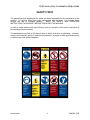
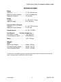
204C
Heavy Duty
Combination
Brake Lathe
Instruction Manual and Parts List
Van Norman
500 57th St., Marion, IA 52302
888-855-1789
Copyright 2006. All Rights Reserved.
Equipment specifications, options and accessories subject to change without notice.
319-377-9101 (FAX)
WARRANTY
Flywheel Grinders, 777 and 204C Brake Lathes
Van Norman will repair and/or replace, free of charge (FOB factory) all such defective
parts, only when returned to factory with shipping charges prepaid. This warranty does not
cover parts and supplies (wheel dresser/diamonds/abrasives) consumed in normal
operation of the machine.
Van Norman disclaims all other warranties, expressed or implied, as to the quality of any
goods, including implied warranties of MERCHANTABILITY and FITNESS FOR
PARTICULAR PURPOSES. UNDER NO CIRCUMSTANCES WHATSOEVER, SHALL Van
Norman BE LIABLE FOR ANY INCIDENTAL OR CONSEQUENTIAL DAMAGES,
WHETHER BASED ON LOST GOODWILL, LOST RESALE PROFITS, WORK
STOPPAGE, IMPAIRMENT OF OTHER GOODS OR ARISING OUT OF BREACH OF ANY
EXPRESS OR IMPLIED WARRANTY, BREACH OF CONTRACT, NEGLIGENCE OR
OTHERWISE, EXCEPT ONLY IN THE CASE OF PERSONAL INJURY.
Because of Van Norman’s constant program of product improvement, specifications are
subject to change without notice.
VAN NORMAN PROVIDES A LIMITED WARRANTY ON PRODUCTS WHEN
PURCHASED IN A NEW AND UNUSED CONDITION TO BE FREE FROM DEFECTIVE
MATERIAL OR WORKMANSHIP FROM DATE OF PURCHASE FOR A PERIOD OF ONE
YEAR.
This warranty does not apply to a product that has been purchased in used condition, that
has failed due to improper installation, repairs, service or that has sustained damage
caused by accident, improper use or shipment.
For further information or questions, please contact Van Norman at 888-855-1789 or fax
319-377-9101.
PLEASE RETAIN THIS WARRANTY FOR YOUR RECORDS
Van Norman
500 57th St., Marion, IA 52302
888-855-1789
319-377-9101 (FAX)
204C Heavy Duty Combination Brake Lathe
RECEIVING SHIPMENT
Upon taking delivery of your machine, carefully inspect the assembly before removing
the crating and packing materials.
If evidence of damage exists, contact the shipper and Van Norman immediately.
Although Van Norman is not responsible for damage incurred during transit, you will be
provided assistance in preparation and filing of any necessary claims.
CAREFULLY READ THIS MANUAL BEFORE ATTEMPTING TO SETUP OR OPERATE THIS
MACHINE.
IMPORTANT NOTE
Always have your serial number ready when communicating with Van Norman
regarding parts or service.
Keep this manual in a safe place.
Date Received:
Serial Number:
Van Norman
(Serial Number location: Upper left corner at rear of unit)
1.
888-855-1789
204C Heavy Duty Combination Brake Lathe
SAFETY FIRST
This manual has been prepared for the owner and those responsible for the maintenance of this
machine. It’s purpose aside from proper maintenance and operations, is to promote safety
through the use of accepted practice.
READ THE SAFETY AND OPERATING
INSTRUCTIONS THOROUGHLY BEFORE OPERATING THE MACHINE.
In order to obtain maximum life and efficiency from your machine, follow all the instructions in
the operating manuals carefully.
The specifications put forth in this manual were in effect at the time of publication. However,
owing to Van Norman’s policy of continuous improvement, changes to these specifications may
be made at any time without obligation.
Van Norman
2.
888-855-1789
204C Heavy Duty Combination Brake Lathe
SAFETY INSTRUCTIONS
1. Read, understand and follow the safety and operating instructions found in this manual.
Know the limitations and hazards associated with operating the machine.
2. Eye Safety: Wear an approved safety face shield, goggles or safety glasses to protect eyes
when operating the machine.
3. Grounding the Machine: Machines equipped with three prong grounding plugs are so
equipped for your protection against shock hazards and should be plugged directly into a
properly grounded three-prong receptacle in accordance with national electrical codes and
local codes and ordinances. A grounding adapter may be used. If one is used, the green
lead should be securely connected to a suitable electrical ground such as a ground wire
system. Do not cut off the grounding prong or use an adapter with the grounding prong
removed.
4. Work Area: Keep the floor around the machine clean and free of tools, tooling, stock scrap
and other foreign material and oil, grease or coolant to minimize the danger of tripping or
slipping. Van Norman/Kwik-Way recommends the use of anti-skid floor strips on the floor
area where the operator normally stands and that each machine's work area be marked off.
Make certain the work area is well lighted and ventilated. Provide for adequate workspace
around the machine.
5. Guards: Keep all machine guards in place at all times when machine is in use.
6. Do Not Overreach: Maintain a balanced stance and keep your body under control at all times.
7. Hand Safety: NEVER wear gloves while operating this machine.
8. Machine Capacity: Do not attempt to use the machine beyond its stated capacity or
operations. This type of use will reduce the productive life of the machine and could cause
the breakage of parts, which could result in personal injury.
9. Avoid Accidental Starting: Make certain the main switch is in the OFF position before
connecting power to the machine.
10. Careless Acts: Give the work you are doing your undivided attention. Looking around,
carrying on a conversation and horseplay are careless acts that can result in serious injury.
11. Job Completion: If the operation is complete, the machine should be emptied and the work
area cleaned.
12. Disconnect All Power and Air to Machine before performing any service or maintenance.
13. Replacement Parts: Use only Van Norman/Kwik-Way replacement parts and accessories;
otherwise, warranty will be null and void.
14. Misuse: Do not use the machine for other than its intended use. If used for other purposes,
Van Norman/Kwik-Way Products Inc. disclaims any real or implied warranty and holds itself
harmless for any injury or loss that may result from such use.
Van Norman
3.
888-855-1789
204C Heavy Duty Combination Brake Lathe
SPECIFICATIONS
Rotor
Capacity………………………….. 4" - 24" (102-610 mm)
Maximum Friction Surface………. 5 "(127 mm)Maximum
Maximum Thickness…………….. 2.5 "(64 mm)
Drum
Capacity…………………………. 6" – 28" (152–711 mm)
Maximum Depth………………… 8.75" (222 mm)
Flywheel (Flat or Stepped)
Capacity…………………………. 6" – 24" (152–610 mm)
Maximum Friction Surface……… 5" (127 mm)
Spindle Speeds…………………. 60, 100, 170 RPM
Feed Speeds
Infinitely Variable 0 to —
Per minute, in. (mm)……………. 3.375" (85 mm)
Per revolution, in. (mm)……….
0.020 (508 mm)
Motor……………………………
1 HP (.700 kw)
Weight
204C
Machine Net Weight…………….. 643 lbs. (292 kg)
Domestic Shipping Weight……… 730 lbs. (331 kg)
Export Shipping Weight………… 835 lbs. (379 kg)
Van Norman is committed to product innovation and improvement and therefore reserves the
right to change product specifications without notice.
Van Norman
4.
888-855-1789
204C Heavy Duty Combination Brake Lathe
INSTALLATION
Machine "Prep"
1. Carefully uncrate the lathe and wash off the anti-rust oil or any dirt accumulated
during shipment. Kerosene or any approved commercial solvent may be used.
DO NOT USE GASOLINE.
Locate and Position
1. Select a location, which provides a permanent LEVEL foundation — preferably a
concrete floor. Ample space should be provided for the operator to move completely
around the machine. We recommend 30" from the wall. Then permanently secure
machine in place using the four mounting feet on each corner of the machine base.
Electrical Motors
1. Additional electrical devices or special wiring that may be required in your area
should be bought locally. Any Overload or Undervoltage protection devices are not
furnished as standard equipment and may be purchased locally or by Special Quote
from Van Norman. The main spindle is to revolve CLOCKWISE when facing the
work light.
2. Main Spindle Motor draws 13.2 amps on 120V wiring and 6.6 amps on 230V wiring.
Lubrication
1. Use regular No. 40 S.A.E. non detergent oil in all cups, the “Zero-Max”, and the main
body.
2. The oil level in both the “Zero-Max” and main body were filled at the factory. Please
check these levels prior to running the machine.
a. Main body oil should be filled to hole (Figure 2A).
b. The “Zero-Max” should be filled to within 3/4 inch of the fill hole (Figure 1).
C
D
B
A
Figure 1
Figure 2
3. The Vertical Shaft (Figure 2C) and Leadscrew Nut (Figure 2D) should be oiled daily
with 3-5 drops of oil.
Van Norman
5.
888-855-1789
204C Heavy Duty Combination Brake Lathe
INSTALLATION (continued)
4. Grease Spindle Bearing (Figure 3) once a month using a lithium based grease with
moly. The grease should be an NLGI Grade 1, GC-LB.
Figure 3
Cleaning / Maintenance
1. Do not use an air hose to clean machine. Use a brush to clear chips away. Clean
daily after use.
2. DO NOT use Gasoline to clean machine, use Kerosene or any approved solvent.
3. If machine is not used on a regular basis, wiping with No. 10 S.A.E. oil between uses
is advisable.
1.
2.
3.
4.
5.
6.
7.
8.
9.
10.
11.
12.
13.
14.
Van Norman
Spindle Stop
Handwheel for Spindle Position
Oil Fill (Oil Daily #30)
On/Off/Light Switch
Oil Fill & Breather
Spindle Arbor
Tool Bar (for Drum Turning) - 204S
Tool Holder Turret
Handwheel to position Tool Bit for Drum Turning - 204S
Chip Tray
Tool Storage Area
Speed Control Handle
Speed Lock Knob
Drain Plug
6.
888-855-1789
204C Heavy Duty Combination Brake Lathe
COMPONENT/CONTROL IDENTIFICATION AND FUNCTION
1. Spindle Stop
2. Handwheel for Spindle Position
3. Oil Fill (Oil Daily #30)
4. On/Off/Light Switch
5. Oil Fill & Breather
6. Spindle Arbor
7. Tool Bar (for Drum Turning) – 204S
8. Tool Holder Turret
9. Handle wheel to position Tool Bit for Drum Turning –204S
10. Chip Tray
11. Tool Storage Area
12. Speed Control Handle
13. Speed Lock Knob
3
4
14. Drain Plug
2
5
1
6
7
8
9
13
12
10
11
Van Norman
7.
888-855-1789
204C Heavy Duty Combination Brake Lathe
STANDARD & OPTIONAL EQUIPMENT
STANDARD MACHINES
204C Disc/Drum Lathe with Powered & Manual Cross-Feed Slides, Base and Standard
Equipment
Part No.
804-2474-01
804-2474-05
804-8651-44
Description
115V, 60 Hz, 1 Ph
230V, 60 Hz, 1 Ph
230V, 50 Hz, 1 Ph
STANDARD EQUIPMENT
804-8690-56
804-8671-10
804-3021-71
804-8665-63
Twin Cutter Assembly
Tool Bar for Drums
Tool Bit Holder for Drums
Carbide Bit Package
Rotor Bits, 4 (3 cutting edges)
Drum Bits, 2 (2 cutting edges)
804-2040-42
000-1806-70
109-1032-09
109-1033-06
804-2040-44
Arbor Components
1" Arbor w/Nut & Washer (25.4 mm)
Spring
Spacer, 1" (25.4 mm)
Spacer, 2" (50.8 mm)
Draw Bar
804-8658-22
804-8658-23
804-8658-24
804-8658-25
804-8658-26
804-8658-27
Double Ended Cone Set for 1" Arbor
Cone, 1.32" x 1.67" (33.53 x 42.42mm)
Cone, 1.36" x 1.71" (34.54 x 43.43mm)
Cone, 1.71" x 2.07" (43.43 x 52.59mm)
Cone, 2.07" x 2.44" (52.59 x 61.98mm)
Cone, 2.44" x 2.89" (61.98 x 73.41mm)
804-8664-64
804-8664-45
101-0243-00
101-0236-05
101-0237-02
804-8664-50
Tapered Cone Set for 1" Arbor
Cone, 1.15"–1.80" (29.21 - 45.72mm)
Cone, 1.70"–2.35" (43.18 - 59.69mm)
Cone, 2.25"–2.90" (57.15 - 73.66mm)
Cone, 3.35"–4.00" (85.09 - 101.6mm)
Cone, 3.90"–4.55" (99.06 - 115.57mm)
109-1011-09
101-0235-40
Clamp Bells
4.25" (107.95 mm) O.D.
5.75" (146.05 mm) O.D. (2 included)
Van Norman
8.
888-855-1789
204C Heavy Duty Combination Brake Lathe
STANDARD & OPTIONAL EQUIPMENT (continued)
Part No.
804-2059-20
108-1061-00
109-1032-09
804-8665-41
101-0230-10
000-0600-70
000-0600-54
000-0600-20
800-1017-39
804-8664-43
804-7803-35
Miscellaneous
Description
Chip Tray
Vented Silencer-Rotor
Spacer, 1 x 1.5 x 1.5
Solid Rotor Silencer, Magnetic Band, .250" x 48" (6.35 x 1219.2 mm)
Automotive Drum Silencer
Hex Key .187" (4.75 mm)
Hex Key .125" (3.18 mm)
Hex Key .312" (7.93 mm)
Hex Key .375" (9.53 mm)
Wrench, Draw Bolt
Wrench, Arbor Nut
OPTIONAL ACCESSORIES
804-2040-42
804-8666-09
804-2040-90
804-8677-10
Arbors
11/16" Arbor with Nut, Cone & Washer, Bore .875"–1.250"
(22.23 - 31.75 mm) 7.375" Long
1" Arbor with Nut/Washer 9.75" L
1 7/8" Arbor with Nut & Washer (for Ammco Adapters) 15.75" Long
2" Arbor with Nut/Washer, 15.75" L
Extended 2" Arbor with Nut & Washer, 19.88" Long
804-8665-15
804-866516
Double Ended Cones used for larger hubbed Drums & Rotors
Cone, 2.82" x 3.18" (73.41–82.80mm)
Cone, 3.20" x 3.56" (82.80–91.95mm)
804-2049-41
804-8664-65
804-8664-50
804-8664-50
804-8664-51
101-0639-00
000-1806-70
804-2053-01
804-2053-00
804-8659-59
804-8659-60
804-8659-61
804-8659-62
804-8659-63
102-0925-00
Van Norman
Light Truck Set for 1" Arbor
Bore Range 3.90"–5.65" (99.06-143.51mm) for Hubless Drums/Discs
Cone, 3.90"–4.55" (99.06–115.5mm)
Cone, 3.90"–4.55" (99.06–115.5mm)
Cone, 4.45"–5.10" (113–129.54mm)
Cone, 5.00"–5.65" (127"–143.51mm)
Spring
Clamp Bell, 6.25" (158.75mm)
Clamp Bell, 7.75" (196.85mm)
Hubless Adapter Set, Small Size for 1" Arbor, Bore Range
1.87"–3.00" (47.5 - 76.2 mm) LH
Rotor Locator LH
Cone, 1.875" x 3.125” (47.63 x 79.38mm)
Spacer LH
Locator Nut LH
Wrench, Spanner
9.
888-855-1789
204C Heavy Duty Combination Brake Lathe
STANDARD & OPTIONAL EQUIPMENT (continued)
Optional Accessories
Part No.
804-8626-13
804-2020-23
804-4161-85
804-4161-86
804-2020-22
804-1168-49
804-8667-75
804-2010-23
804-8631-85
804-8631-86
804-8631-88
804-8631-89
804-8631-85
804-8631-86
804-8631-88
804-8631-89
804-8656-98
804-8657-12
804-8626-14
804-8657-08
804-4161-85
804-4161-86
804-2020-22
804-1168-49
Van Norman
Description
Hubless Adapter Set, Large Size for 1" Arbor, Bore Range
4.00"–5.75" (101.6-146.05 mm)
Rotor Locator
Cone, 3.68" x 5.93" (93.47 x 150.62mm)
Spacer
Locator Nut
Wrench, Spanner
Hubless / Composite Rotor Adapter Kit
Hubless Adapter Set, Std. Size
Backing Plate for 804-8631-86, 804-8631-87, 804-8657-12,
804-8656-98
Adapter Plate, Taurus/Sable,G.M.,“W-Body,” Lincoln
Backing Plate, Chevy 1500 (for 804-8631-89)
Adapter Plate, Chevy 1500
Composite Rotor Backing Plates for 804-2010-23 Adapters
Backing Plate for 804-8631-86, 804-8631-87, 804-8657-12,
804-8656-98
Adapter Plate, Taurus/Sable,G.M., “W-Body,” Lincoln
Backing Plate, Chevy 1500 (for 804-8631-89)
Adapter Plate, Chevy 1500
Adapter Plate, Jeep Cherokee
Adapter Plate, Eagle Premier
Hubless Adapter Set, Large Size for 2" Arbor, Bore Range
4.00"–5.75" (101.6–146.0mm)
Rotor Locator LH
Cone, 3.68" x 5.93" (93.4–150.6mm)
Spacer
Locator Nut LH
Wrench, Spanner
10.
888-855-1789
204C Heavy Duty Combination Brake Lathe
STANDARD & OPTIONAL EQUIPMENT (continued)
Optional Accessories
804-8664-66
804-8664-53
804-8664-54
804-8664-55
804-8664-56
804-8664-57
804-8664-58
804-8664-59
101-0638-01
804-8662-02
804-7803-05
804-7803-01
Medium Truck Set, for 2" Arbor, Bore Range 2.15"–6.10"
(54.61–154.94mm) for Hubless Drums /Discs
Cone, 2.15"–2.80" (54.6–71.1mm)
Cone, 2.70"–3.35" (68.5–85.0mm)
Cone, 3.25"–3.90" (82.5–99.0mm)
Cone, 3.80"–4.45" (96.5–113.0mm)
Cone, 4.35"–5.00" (110.4–127.9mm)
Cone, 4.90"–5.55" (124.4–140.9mm)
Cone, 5.45"–6.10" (138.4–154.9mm)
Spring
Clamp Bell, 7.75” (196.85 mm) (2 included)
Spacer, 2” (50.8 mm)
Spacer, 3” (76.2 mm)
804-8664-59
804-8664-60
804-8664-61
804-8664-62
804-8664-63
101-0638-01
804-3000-84
804-7803-05
804-7803-01
Heavy Truck Set, for 2" Arbor, Bore Range 5.45"–8.30" (13.8.4–
210.8mm) for Hubless Drums / Discs
Cone, 5.45"–6.10" (138.4–154.9mm)
Cone, 6.00"–6.65" (152.4–168.9mm)
Cone, 6.55"–7.20" (166.3–182.8mm)
Cone, 7.10"–7.75" (180.3–196.8mm)
Cone, 7.65"–8.30" (194.3–210.8mm)
Spring
Clamp Bell, 9.25" (234.95 mm) (2 included)
Spacer , 2" (50.8mm)
Spacer , 3" (76.2mm)
804-8665-64
804-8665-61
804-8665-62
804-7803-18
804-1408-22
804-1290-05
101-0230-10
108-1062-00
804-8665-42
804-8665-41
804-8665-43
804-8665-44
804-8668-08
804-8668-09
804-8668-10
804-2049-60
804-2049-69
804-3029-49
804-8665-45
Miscellaneous
Rotor Bits, Pkg/10 (3 cutting edges) 1/32" (.79 mm) Radius
Rotor Bits, Pkg/10 (3 cutting edges) 1/64" (.4 mm) Radius
Drum Bits, Pkg/10 (2 cutting edges)
Solid Carbide Bit, .375" (9.53 mm) Shank
Heavy Duty Tool Holder & Bit
Tool Bit for 804-1408-22
Automotive Drum Silencer
Vented Rotor Silencer
Truck Drum Silencer, 2.75" (69.85 mm) wide
Solid Rotor Silencer Magnetic Band, .25" x 4" (6.35 x 101.6 mm)
Brake Drum Wear Limit Gage, Range 6"–22" (152.4-558.8 mm)
Rotor Micrometer, Range .30"–1.30" (7.62-33.02 mm)
Disc Rotor Swirl Finisher, Non-Directional
Replacement Pads, 25, 80 Grit
Replacement Pads, 25, 120 Grit
Drum Grinder for 204C,115V, 50 / 60 Hz, 1 Ph
T-Bar Holder
Tool Bar Extension, Small Drum Adapter
Safety Shield
804-8664-67
Van Norman
11.
888-855-1789
204C Heavy Duty Combination Brake Lathe
OPERATION
SPEEDS
1. Spindle speeds are 60, 100, and 170 RPM. To change RPM loosen thumb screw
(Figure 4 A & B). To remove belt guard (machine must be off) loosen wing nut
(Figure 4C), lift motor to free belt and put belt in proper groove. Replace motor and
tighten with medium tension on belt, replace belt guard. A larger diameter drum or
rotor requires a lower RPM. For most applications, Van Norman recommends the
middle pulley groove for passenger cars and light truck brake drums and rotors. The
outer pulley groove is for extremely small rotors and drums and the inner pulley
groove for very large drums and rotors.
A
C
B
Figure 4
FEED SLIDE
1. Feeds per revolution are 0 to .020". Feed per revolution should be as high as
possible for most profitable operation. Drums require a good finish. A setting of
.020" is used for rough cuts.
2. A large diameter drum or rotor requires a higher feed.
3. To change speeds loosen knob (Figure 5A) and move handle (Figure 5B), to desired
speed and lock knob.
Figure 5
B
A
Van Norman
12.
888-855-1789
204C Heavy Duty Combination Brake Lathe
OPERATION (continued)
CHATTER CONTROL
1. Brake drums are dish or bell shaped and have a tendency to chatter. This can result
in a wavy or chatter finish accompanied by excessive noise. THE VIBRATION
DAMPENER BELT MUST BE USED AT ALL TIMES to prevent chatter. Securely
wrap belt around the outside of the drum or use proper “O” ring type on outside of a
rotor.
2. Dull, broken chipped or improper tool bits will cause chatter. ALWAYS use tool bits
supplied by the original manufacturer as they are designed to do a specific job.
3. A loose carbide tip on the tool holder will cause chatter. Make sure screw holding
carbide tip grips tip firmly.
4. A dirty uneven surface will crack the carbide tip and/or chatter.
TOOL BITS
1. This lathe is supplied with replaceable type throw-away carbide tips, part no. 8048665-62 (Figure 6) for the drum cutters and part no. 804-8665-61 for the rotor
cutters, (Figure 7).
Figure 6
Figure 7
INSTALLATION OF ARBOR
1. Select correct size mandrel for the work to be done, either a 1" diameter for work
that is 150 pounds or less or the heavy-duty 2" mandrel for work 150 to 500 pounds.
2. Slide mandrel into spindle taper.
IMPORTANT: Both mandrel and spindle tapers must be clean or else mandrel will
run out and taper may be damaged. Align pin in mandrel with slot in main spindle.
Screw in draw bar (Figure 8A), and lock tightly. DO NOT tighten excessively. Driver
pin will prevent arbor from slipping. Remove mandrel easily (Mandrel has nonlocking taper) by loosening nut then tapping lightly into the draw bar.
A
B
Van Norman
13.
Figure 8
888-855-1789
204C Heavy Duty Combination Brake Lathe
OPERATION (continued)
RECONDITIONING DRUMS
1. The knob (Figure 8B) should be loosened when turning drums to insure spindle will
move out during operation. This screw must be tightened when cutting rotors.
2. This knob (Figure 9) should be tightened when doing drums and slide is in position.
Loosen when cutting rotors.
Figure 9
3. To engage feed of main spindle push lever (Figure 10A), to the right of handwheel
(Figure 10B), is the main control to move the main spindle “in” or “out”.
B
A
Figure 10
4. Crank (Figure 11) is used for moving the tool bit into the brake drum on the 204S.
This crank is graduated into thousandths and is direct reading. Example: If crank is
moved out .030", drum will be enlarged .030".
Figure 11
Van Norman
14.
888-855-1789
204C Heavy Duty Combination Brake Lathe
OPERATION (continued)
5. To disengage feed loosen wing nut (Figure 12A) and slide stop (Figure 12B) to
desired position.
6. Reset stop (Figure 12B) every time machine is used on a different width drum. If
properly set, the machine will disengage automatically when it reaches the stop.
B
A
Figure 12
7. Measure the diameter of the drum with a micrometer to determine that the drum will
be within maximum reboring limits after reconditioning. It should also be in good
general condition.
8. Set the spindle speed to match the drum size (Figure 4, Page 12). Move the V-belt
on the pulley to the correct groove.
9. Mount the drum on the arbor using the proper adapters, cones and spacers (Figure
13).
Figure 13
Van Norman
15.
888-855-1789
204C Heavy Duty Combination Brake Lathe
OPERATION (continued)
10. Wrap and secure the drum silencer band tightly around the drum (Figure 14).
11. Turn the cross feed handwheel and the spindle feed handwheel to their maximum
clockwise position. Then back off the cross feed handwheel 2 turns and the spindle
feed handwheel 4 turns.
12. Position the tool bar by loosening the tool bar clamp nut (Figure 14 & 15) and sliding
the tool bar inward toward the drum until the tool bit is close to the surface that is
going to be machined. The entire tool bar may also be swiveled to achieve the best
cutting position.
Figure 14
Figure 15
13. Turn the drum by hand to be sure that it runs true. Turn the lathe on and advance
the tool bit manually until it just contacts the drum surface and makes a scratch cut.
Back the tool bit off, stop the lathe. Loosen the arbor nut and rotate the drum onehalf turn. Retighten the nut, turn the lathe on and make a second scratch cut, stop
the lathe. If the first and second scratch cuts are opposite one another (180° apart)
remove the drum from the arbor. Check the mounting adapters and the arbor for
nicks, burrs or chips. Clean if necessary. If the scratches are side by side, proceed
turning the drum.
14. Turn the spindle feed handwheel until the deepest worn groove of the drum is
opposite the point of the tool bit. Advance the tool bit into the bottom of the groove
by rotating the tool bit into the bottom of the groove by rotating the cross feed
handwheel counter-clockwise.
15. The depth of cut dial will show the approximate reconditioned diameter of the drum.
Make sure that the resurfaced drum will be within the limits cast into the drum.
16. Roughing cuts should be no deeper than .010” (.25mm): finish cuts no shallower
than .002” (.05mm). Usually no more than 2 cuts are required to resurface a drum.
With the lathe running, set the depth of cut, dial to the desired depth and lock the
cross slide by tightening the cross slide locking knob.
Van Norman
16.
888-855-1789
204C Heavy Duty Combination Brake Lathe
OPERATION (continued)
TURNING DISC BRAKES
1. Tighten thumb screw (Figure 8 B Page 13)
2. Loosen knob (Figure 9 Page 14)
3. Each brake disc should be carefully inspected for scoring, rust, ridges (at the inner
and outer circumference of the rotor) and hard spots. Any excessive wear or
deformity should be noted and, if not within acceptable limits, the rotor should be
replaced. Using a micrometer check the thickness of the rotor in at least three
points around the circumference about 1" (2.54 cm) in from the outer diameter. If
the rotor thickness varies between readings it should be machined. However, if the
thickness is less than the minimum established by the manufacturer or it will be after
resurfacing, the rotor should be replaced. NOTE: The minimum refinished thickness
dimension is cast into the rotor.
4. Mount the rotor on the arbor (Figure 16) note that the rotor is centered from hub with
two cones on the Timken bearings. (Figure 16) shows a disc set-up with the hubless
adapter. Install the silencer band, this is easily done by stretching the band around
the outside of the rotor (Figure 17).
Figure 16
Figure 17
5. Adjust pulley drive belts for the desired speed (Page 12).
Van Norman
17.
888-855-1789
204C Heavy Duty Combination Brake Lathe
OPERATION (continued)
6. Feed in the slide assembly with crank [Figure 18 A). (Figure 18 B) Locking nut is
turned in to engage slide power. (Must be loose to turn slide in or out manually.
Figure 18
7. Feed in the moveable claw with graduated dial [Figure 18 A) until there is slight
contact with disc brake pad surface. Tightly lock the moveable claw with binder
[Figure 18 B). Turn the cross feed handle to move the tool bits all the way in and off
the disc pad surface. Determine amount of stock to be removed to clean up both
disc brake pad surfaces. NOTE: Maximum cut per side is .015". Engage feed by
tightening knob. Use a slow cross feed of approximately .004" per revolution (zero
max control).
8. After facing the surface a non-directional finish should be applied.
STORAGE
MAINTENANCE
If machine is to be stored for a long period of time, the following should be done:
1. Unplug machine, turn the slide into machine base and lock back spindle
thumb screw to keep spindle in position.
2. Take tension off all drive belts.
3. Spray machine with a rust inhibiting oil and cover machine to protect it from dust and
dirt.
Van Norman
18.
888-855-1789
204C Heavy Duty Combination Brake Lathe
MAINTENANCE (continued)
DISASSEMBLY, REPAIR, REPLACEMENT AND REASSEMBLY
1.
2.
3.
4.
5.
Unplug machine.
Remove tooling from machine.
Remove arbor by loosening draw bar.
Drain oil.
You are now ready to start repair.
SPINDLE BEARING
NOTE: It is rare for the spindle bearing to need replacement.
1.
2.
3.
4.
Check that items 1-5 above have been completed.
Remove belt guard.
Loosen wing nut (Page 30, Item 14) to allow motor to lift up to remove belt (Item 12).
Punch out groove pin (Page 26, Item 2) remove oiler (Item 4), then lift out
handwheel assembly.
5. Loosen screws (Page 28, Item 12), (Page 12, Item 34).
6. Pull back on bearing housing (Page 19, Item 11), turn side ways, pull shaft (Item 28)
removing (Items 29, 30, and 31).
7. Remove washer (Item 4) and bolt (Item 23), hold bearing housing (Item 11) and
spindle, and remove from machine.
8. Now remove and replace spindle bearing (Page 17, Item 3).
9. Reverse above for assembly.
10. Always replace front and rear seals, Part No. 804-1415-69.
REPLACE ZERO MAX SIDE SEALS Worm Shaft & Output Shaft Seals (Page 17)
1. Remove the two screws (Item 23) and lift zero max off machine.
2. Remove couplings (Item 19 & 33), remove seals and replace them. Reassemble.
REPLACE FRONT BEARING OIL SEAL (Page 17, Item 4)
1. Crank spindle back to farthest position.
2. Pull seal out and press new seal in.
Van Norman
19.
888-855-1789
204C Heavy Duty Combination Brake Lathe
BASIC MACHINE
Van Norman
20.
888-855-1789
204C Heavy Duty Combination Brake Lathe
BASIC MACHINE
Item
1
2
4
5
6
7
8
9
12
13
15
16
17
18
19
20
21
22
23
24
25
26
28
29
30
32
33
34
35
36
37
38
39
40
41
42
43
44
45
Van Norman
Part No.
804-2043-00
804-1184-28
804-3020-06
804-1415-69
804-3040-65
804-1050-21
000-1154-60
804-3040-10
804-2040-03
804-2040-13
804-2040-12
804-2040-97
804-2040-10
804-2040-39
804-1077-11
804-2041-20
000-0165-27
000-1180-10
000-1150-10
000-0102-86
000-1180-28
000-1160-17
804-2048-21
804-2040-94
804-2043-17
804-2040-93
804-1252-66
804-1243-49
000-0592-22
804-2040-61
000-0102-86
000-1160-17
804-2040-09
804-1050-21
804-2041-63
804-1243-47
804-1115-58
804-1235-50
804-8656-94
804-8043-17
Description
Body
Breather
Bearing (Prior to 1984)( Not Shown)
Front Bearing Oil Seal
Work Light Window
Screw (10-32 x 3/8)
Washer (#10)
Spindle Key
Spindle
Output Shaft Spiral Gear
Shaft
Shim Pack (.015)
Shim Pack (.005)
Cap
Oil Seal
Coupling (Mach)
Head Cap Screw 1/4 X 20 X .625)
Lockwasher (1/4”)
Washer 1/4" Flat
Head Cap Screw (5/16-18 x 3/4)
Lockwasher (5/16)
Washer, 5/16 Flat
Zero Max Support Bracket
Decal
Zero Max Assembly
Decal
Disc Coupling #FD-20
Coupling #FC-20 x.75
BHCS (1/4 - 20 x .375)
Zero Max Coupling Guard
HHCS (5/16 - 18 x 3/4)
Washer 5/16 Flat
Worm Bearing Cap
Screw (10-32 x 3/8)
Pointer
Roller Bearing
Groove Pin (3/16 x 1 1/4)
SSS (1/2-20 x 1)
Coupling #FC-20 x .375
Zero Max Handle Assembly
21.
Qty
1
1
1
1
4
4
1
1
1
1
2
2
1
2
1
4
4
4
2
2
2
1
1
1
1
2
1
2
1
6
6
1
1
1
1
1
4
2
1
888-855-1789
204C Heavy Duty Combination Brake Lathe
VERTICAL SHAFT ASSEMBLY
Van Norman
22.
888-855-1789
204C Heavy Duty Combination Brake Lathe
VERTICAL SHAFT ASSEMBLY
Item
1
2
3
4
5
7
8
9
11
12
14
15
16
17
18
19
20
21
22
23
24
25
26
27
28
29
30
31
33
34
35
36
37
Van Norman
Part No.
804-2043-00
804-1094-24
804-2040-19
804-1062-54
000-4400-10
804-2040-75
804-2040-18
804-2040-76
804-2040-19
804-1094-24
804-1071-80
804-2040-14
804-1235-50
804-2040-16
804-1243-48
000-1035-51
804-1243-51
804-1243-52
804-1094-24
804-2040-15
804-1160-74
804-2040-21
804-2040-20
000-7204-96
804-1243-94
804-2040-40
804-2040-22
804-1243-53
804-8035-72
804-1240-25
804-8016-58
000-7000-37
804-1166-25
Description
Body
Groove Pin
Upper Collar
Oiler
Handwheel Handle
Vertical Shaft Handwheel
Handwheel Spring
Gear
Lower Collar
Groove Pin
Pilot Key
Shaft
SSS 1/2-20 x 1
Ball Bearing Housing
O-Ring
Hex Nut (1/2-20)
Ball Bearing
Retaining Ring
Groove Pin
Vertical Shaft Helical Gear
Retaining Ring
Feed Clutch Hub Assembly
Vertical Shaft Clutch
Spiral Pin
Compression Spring
Hub Detent
Clutch Lever
Lever Ball
Dowel Pin, 3/8 x 2
SSS (3/8-24 x 1/2)
Button Soc. Head Screw, 3/8-24 x 1
Dowel Pin (1/4 x 1 1/4)
Oiler
23.
Qty.
1
1
1
1
1
1
1
1
1
1
1
1
1
1
1
1
1
1
1
1
1
1
1
1
1
1
1
1
1
1
1
1
1
888-855-1789
204C Heavy Duty Combination Brake Lathe
SPINDLE CLAMP ASSEMBLY
Van Norman
24.
888-855-1789
204C Heavy Duty Combination Brake Lathe
SPINDLE CLAMP ASSEMBLY
Item
1
2
3
4
5
6
7
8
9
10
11
12
13
14
15
16
17
18
19
20
21
22
23
24
25
26
27
28
29
30
31
Van Norman
Part No.
804-2040-26
804-8035-81
804-1243-55
000-1155-33
804-2040-63
000-1180-28
000-0167-64
804-1247-55
804-8073-76
804-2040-27
804-2042-97
804-1176-62
804-2041-51
000-1150-10
000-0100-57
804-2042-98
804-8641-77
804-1405-72
804-1243-45
800-1408-51
800-8016-56
804-1415-69
000-0102-86
000-1160-17
804-2040-72
804-2040-70
804-2040-69
804-2040-23
804-2040-62
804-1162-07
804-2040-24
Description
Push Rod
Retaining Ring
Compression Spring
Washer, 3/8 Flat
Sleeve
Lockwasher, (5/16)
SHCS (5/16-18 x 1/2)
Retaining Ring (5000-112)
Wing Nut (5/16-18
Release Dog Assembly
Bearing Housing
SSS (3/8-16 x 1/2)
Shaft
Washer, 1/4 Flat
HHCS (1/4-20 x 1)
Cover
Bearing Locknut
Thrust Washer
Roller Bearing
Thumb Screw (3/8-16 x 3/4)
Grease Fitting
Oil Seal
HHCS (5/16-18 x 3/4)
Washer, 5/16 Flat
Rear Bearing
Spindle Worm Gear
Work Spindle Sleeve
Feed Screw
Guard
O-Ring
Feed Screw Nut & Gear
25.
Qty.
1
1
1
1
1
3
3
1
1
1
1
1
1
3
3
1
1
1
1
1
1
1
4
4
1
1
1
1
1
1
1
888-855-1789
204C Heavy Duty Combination Brake Lathe
RIGHT REAR OF MACHINE
35
35
Van Norman
26.
888-855-1789
204C Heavy Duty Combination Brake Lathe
RIGHT REAR OF MACHINE
Item
1
2
4
5
6
7
8
10
11
12
13
14
15
16
17
18
19
20
21
22
23
26
27
28
29
30
31
32
33
34
35
Van Norman
Part No.
Bulk
800-8014-71
000-1261-01
000-1160-17
000-1180-28
000-0102-86
804-1405-24
804-8682-62
804-1125-05
804-8676-69
000-1160-17
804-8073-76
804-2043-24
804-1417-83
804-2040-37
000-0173-02
000-1155-50
804-2040-36
000-1155-50
804-1069-77
000-1160-17
804-1125-05
804-8682-63
804-1077-11
804-2040-09
804-2040-10
804-1243-47
804-2040-71
800-8014-74
804-1069-77
000-0485-26
Description
Cable, 36”'
Strain Relief
110V Motor Cable
Washer, (5/16)
Lockwasher (5/16)
HHCS (5/16-18 x 3/4)
Motor
Pulley
Key
Poly-V Belt
Washer (5/16)
Wingnut (5/16-18 x 1/2)
Motor Belt Guard
Thumbscrew (5/16-18 x 1/2)
Pin
SHCS (1/2-13 x 1)
Washer (1/2, Flat)
Motor Bracket
Washer (1/2, Flat)
SSS 5/16-18 x 1
Washer (5/16)
Key
Pulley
Seal
Worm Bearing Cap
Shim
Roller Bearing
Shaft
Tiger Grip Nut
Stud
¼ x 20 x 3/8 Set Screw
27.
Qty.
1
2
1
4
4
4
1
1
1
1
1
1
1
1
1
1
1
1
1
1
3
1
1
1
1
1
1
1
2
1
2
888-855-1789
204C Heavy Duty Combination Brake Lathe
804-8690-56 DISC ASSEMBLY
1
2
3
21
22
5
20
18
17
19
10
15
6
4
7
8
Van Norman
14
16
28.
9
13
12
11
888-855-1789
204C Heavy Duty Combination Brake Lathe
804-8690-56 DISC ASSEMBLY
Item
1
2
3
4
5
6
7
8
9
10
11
12
13
14
15
16
17
18
19
20
21
22
Van Norman
Part No.
804-8693-77
804-1407-54
804-1258-12
804-1405-35
804-8678-54
804-8678-55
804-8690-23
804-8690-24
804-2042-70
000-7300-41
804-8689-51
804-8689-52
804-8659-49
804-1258-10
804-8689-78
000-0166-08
804-1199-25
804-1292-79
000-0165-27
804-2043-20
000-0165-27
800-8684-34
Description
Hand Lock Down
Washer, .312 Flat
Dowel Pin (.75 x 2)
Spring
R.H. Tool Holder
L.H. Tool Holder
Base Plate
Feed Dial Block
Feed Screw
#5 Woodruff Key
Micrometer Knob
Zeroing Sleeve
Zeroing Decal
Finger Spring Washer
Spring Washer
SHCS 1/4-20 x 1.0
Dowel Pin 3/16 x 1.5
Clamp with Spring
Clamp Screw
Guard
SHCS 1/4-20 x .62
Rubber Seal Washer
29.
Qty.
2
2
2
1
1
1
1
2
2
2
2
2
2
2
2
4
2
2
2
1
2
4
888-855-1789
204C Heavy Duty Combination Brake Lathe
POWER FEED ATTACHMENT FOR FACING DISC BRAKES
Van Norman
30.
888-855-1789
204C Heavy Duty Combination Brake Lathe
POWER FEED ATTACHMENT FOR FACING DISC BRAKES
Item Part No.
Description
1
804-2041-42
Gib
2
000-0491-23
SSS (3/8-16 x 1 3/4)
3
804-1405-31
Knob
4
804-1116-33
Brass Plug
6
000-0170-35
SHCS (3/8-16 x 1 1/2)
7
804-2041-18
Power Facing Feed Slide
8
000-0170-27
SHCS (3/8-16 x 1)
9
000-0168-02
SHCS (5/16-18 x 1)
10
804-2041-62
Belt Idler
11
804-1087-11
Oilite Bushing
12
804-2041-65
Idler Bracket
13
804-1258-36
Oilite Bushing
14
804-2041-26
Pulley
15
000-0482-91
SSS (10-32 x 1/2)
16
804-1405-83
Belt
17
804-2043-00
Body (Mach.)
18
000-0173-02
SHCS (1/2-13 x 1)
19
804-2041-17
Power Facing Feed Knee
20
804-2041-22
Slide Feed Screw Nut
21
804-2041-30
Collar
22
804-1111-39
Oilite Bushing
24
804-2041-31
Plate
25
000-0170-27
SHCS (3/8-16 x 1)
26*
804-2041-23
Feed Screw
27
804-8659-73
Feed Screw Assembly
28
794-1099-25
Pin (1/4 x 2)
29
804-1100-49
Woodruff Key
30
804-2041-32
Collar
32
804-1250-52
Belt
33
804-2041-67
Pulley Guard
34
000-0595-28
Screw (10-32 x 3/8)
35
804-2041-44
Stop Nut
36
804-2041-59
Power Feed Screw Drive Nut
37
804-2041-36
Feed Screw Crank Assembly
38
800-8047-64
BHCS (10-32 x 3/8)
39
804-2041-29
Pulley
40
804-1115-39
SSS (10-32 x 3/8)
41
804-1051-33
Woodruff Key (#3)
42
804-2041-28
Drive Shaft
43
804-1051-33
Woodruff Key (#3)
44
804-7258-36
Oilite Bushing
45
804-2042-46
Idler Arm
46
000-1155-33
Washer (.375 Flat)
47
804-1087-11
Oilite Bushing
48
000-0170-27
SHCS (3/8-16 x x1)
49
804-2041-62
Belt Idler
50
000-1155-33
Washer (.375 Flat)
51
000-0170-27
SHCS (3/8-16 x 1)
* for customer orders, use 804-8659-73
Van Norman
31.
Qty.
1
2
1
1
2
1
1
2
1
1
1
1
1
1
1
1
4
1
1
1
1
1
4
1
1
1
1
1
1
1
1
1
1
1
4
1
1
1
1
1
1
1
1
1
1
1
1
1
888-855-1789
204C Heavy Duty Combination Brake Lathe
TOOL BAR ASSEMBLY
Item
1
2
3
4
5
6
7
8
9
10
11
Van Norman
Part No.
804-8668-06
000-0505-20
804-8030-07
804-8668-07
000-0160-14
804-8665-52
804-3021-71
804-8664-42
804-2043-03
804-2040-30
804-2043-01
Description
Drum Bar
SSS .375-16 x .500
SS .312-24 x .375
Tool Bit Holder
SHCS 8-32 x .625
Drum Tool Bit Package of 10
Tool Bit Holder Assembly
Flange Nut
Drum Bar Clamp Stud
Drum Bar Clamp Plate
Drum Bar Holder
32.
Qty.
1
2
1
1
1
1
1
1
1
1
1
888-855-1789
204C Heavy Duty Combination Brake Lathe
ELECTRICAL EQUIPMENT
Van Norman
33.
888-855-1789
204C Heavy Duty Combination Brake Lathe
ELECTRICAL EQUIPMENT
Item
1
2
3
4
5
6
7
8
9
11
12
13
14
15
17
18
19
20
21
22
23
24
25
Van Norman
Part No.
804-2043-00
804-1413-57
800-8014-69
804-1415-26
804-1050-21
804-1413-56
804-8657-78
804-1050-21
804-8109-79
804-1413-64
804-8030-34
804-8657-91
000-1155-50
804-1405-24
804-1409-99
804-1405-86
794-8013-15
804-2042-90
804-8052-84
804-8666-49
000-0123-47
800-8014-71
001-1601-76
Description
Body
Electrical Cover
Strain Relief
Wire Clip
Screw (10-32 x 3/8)
Switch
Electrical Box
Screw (10-32 x 3/8)
Boot
Motor and Light Decal
Washer, 1/2
Electrical Cover
Washer, 1/2
Motor
Socket and Bulb Holder Assembly
Bulb (110V)
Pipr Nipple, (3/8)
Light Bracket
Hex Nut (1/4-20)
Pipe Nipple Nut
FHHCS (1/4-20 x 3/4)
Strain Relief
Bulb (220V)
34.
Qty.
1
2
5
1
1
2
2
2
1
1
1
1
1
1
1
1
1
1
1
1
1
1
1
888-855-1789
204C Heavy Duty Combination Brake Lathe
Van Norman
35.
888-855-1789
204C Heavy Duty Combination Brake Lathe
Van Norman
36.
888-855-1789
204C Heavy Duty Combination Brake Lathe
Van Norman
37.
888-855-1789
204C Heavy Duty Combination Brake Lathe
Van Norman
38.
888-855-1789
Van Norman
A Division of Kwik-Way Products Inc.
500 57th St., Marion, IA 52302 USA
888-855-1789 or 319-377-9421
319-377-9101 (FAX)
www.van-norman.com
[email protected]