1
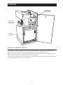
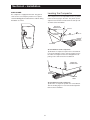
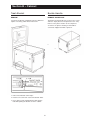
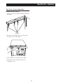
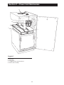
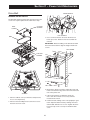
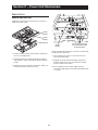
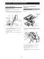
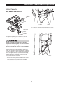
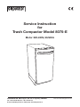
Service Instruction
for
Trash Compactor Model 8075-E
Motor 220-240V, 50/60Hz
Disperator AB Mälarvägen 9, SE-141 71 Segeltorp, SWEDEN Tel: +46 8 724 01 60, Fax: +46 8 724 60 70
E-mail: [email protected], Web page: www.disperator.se
Ref: Serv-8075/Eng/CE/110311
Safe Servicing Practices
Safe Servicing Practices
To avoid personal injury and/or property damage, it is important that Safe Servicing Practices be observed.
The following are some limited examples of safe practices.
1. DO NOT attempt a product repair if you have any doubts as to your ability to complete it in a safe and satisfactory manner.
2. Before servicing or moving an appliance, remove the power cord from the electrical outlet, trip the circuit breaker to the OFF position, or remove the fuse.
3. Never interfere with the proper operation of any safety device.
4. USE ONLY REPLACEMENT PARTS CATALOGED FOR THIS APPLIANCE. SUBSTITUTIONS MAY DEFEAT COMPLIANCE WITH SAFETY STANDARDS.
5. GROUNDING: The standard color coding for safety ground wires is GREEN, or GREEN WITH
YELLOW STRIPES. Ground leads are not to be used as current-carrying conductors. It is EXTREMELY important that the service technician re-establish all safety grounds prior to completion of service. Failure to do so will create a hazard.
6. Prior to returning the product to service, ensure that:
• All electrical connections are correct and secure
• All electrical leads are properly dressed and secured away from sharp edges, high-temperature components, and moving parts
• All non-insulated electrical terminals, connectors, heaters, etc., are adequately spaced away from
all metal parts and panels
• All safety grounds (both internal and external) are correctly and securely connected
• All panels are properly and securely re-assembled
NOTE
NOTE
This service manual is intended for use by persons having electrical and mechanical training and
a level of knowledge of these subjects considered acceptable in the appliance repair trade.
DISPERATOR cannot be responsible, or assume any liability, for injury or damage of any kind
arising from the use of this manual.
Grounding Instructions
IMPORTANT: TO REDUCE THE RISK OF ELECTRIC SHOCK - PLEASE READ CAREFULLY.
FOR PERSONAL SAFETY, THIS APPLIANCE MUST BE PROPERLY GROUNDED.
IF THERE IS ANY DOUBT AS TO WHETHER THE WALL RECEPTACLE IS PROPERLY GROUNDED,
HAVE IT CHECKED AND PROPERLY GROUNDED BY A QUALIFIED ELECTRICIAN.
A 220-240 volt, 50-60 Hz., A.C., 10 amp fused and grounded electrical supply is required (time-delay
fuse or circuit breaker is recommended). It is recommended that a SEPARATE CIRCUIT serving only this
appliance be provided.
DO NOT USE AN EXTENSION CORD OR PLUG ADAPTER WITH THIS APPLIANCE.
Table of Contents
Table of contents
Safe Servicing Practices . ......................................... 2
Grounding Instructions ............................................. 2
Features ..................................................................... 4
Section A – Installation ............................................. 5
Free-Standing . ............................................................ 5
Built-In Installation . ..................................................... 5
Mounting Straps ..................................................... 5
Under-Counter Opening ......................................... 5
Cord Clamp ............................................................ 6
Leveling the Compactor .............................................. 6
Section B – Cabinet . ................................................. 7
Trash Bucket ............................................................... 8
Remove . ................................................................. 8
Bucket Handle ............................................................. 8
Remove and Replace .............................................. 8
Slide Rails (Cabinet)..................................................... 9
Remove and Re-install ............................................ 9
Slide Rails (Bucket) ...................................................... 9
Remove and Re-install ............................................ 9
Door Assembly .......................................................... 10
Remove and Re-install .......................................... 10
Reverse Door Hinge Position ................................ 10
Safety Interlock Actuator . ......................................... 11
Remove and Re-install .......................................... 11
Gasket Assembly....................................................... 12
Remove and Re-install .......................................... 12
Top Trim Cover Assembly ......................................... 13
Remove and Re-install .......................................... 13
Section C – Power Unit Mechanism ......................
Drive Belt ...................................................................
Remove and Re-install .........................................
Main Motor ................................................................
Remove and Replace ...........................................
Complete Power Unit Mechanism ............................
Remove and Re-install .........................................
Drive Wheels..............................................................
Remove and Replace ...........................................
Ram Screw Assembly ...............................................
Remove and Replace ............................................
Section D – Electrical Components .......................
Start Switch . .............................................................
Remove and Replace ...........................................
Access to Components . ...........................................
Remove Cabinet Cover ........................................
Re-install Cabinet Cover . .....................................
Control Panel Assembly ............................................
Remove and Re-install .........................................
Display Module Assembly .........................................
Remove and Re-install .........................................
Key Switch.................................................................
Remove and Replace ............................................
Interlock Switch Assembly.........................................
Remove and Re-install ........................................
Upper Limit Switch Assembly....................................
Remove and Replace ...........................................
Lower Limit Switch ....................................................
Remove and Replace ...........................................
Motor Centrifugal Switch Assem ..............................
Remove and Replace ...........................................
Motor Capacitor ........................................................
Test, Remove and Replace ...................................
21
22
22
22
22
24
25
25
26
26
26
26
27
27
27
27
28
28
28
28
29
29
Section E – Troubleshooting
Troubleshooting Table................................................ 31
Section F – Specifications
Specifications Table................................................... 34
Section G – Diagrams and Parts Lists
Wiring Schematic ...................................................... 34
Drawing and Parts List – Cabinet . ............................ 35
Drawing and Parts List – Mechanism . ...................... 36
14
15
15
16
16
17
17
17
17
18
18
Features
ELECTRICAL
COMPONENTS
(SECTION D)
POWER UNIT
MECHANISM
(SECTION C)
CABINET
(SECTION B)
How the compactor works
The compactor compresses kitchen trash up to 1/6 of its original volume. It will compact normal kitchen trash
including cartons, glass and plastic bottles, containers and jars, tin cans, wrappings, boxes etc.
When you start the compactor, an electrically powered ram moves down into the trash bucket, compresses the
trash and then returns to the “UP” position and shuts off automatically.
NOTE: The ram travels about 2/3 of the way down into the trash bucket. Because of this, the trash bucket must be
at least 1/3 full before you will notice any compression.
Section A – Installation
Your compactor has been designed to require
minimum space without loss of capacity whether
free-standing or built-in.
Built-in Installation
mounting straps
Free-Standing
TOP OF
COMPACTOR
As shipped, the compactor is only configured for
built-in installations. This appliance can be converted
from built-in to free-standing with the use of Toe Kick
Accessory Kit Model 15TCTK (sold separately).
If additional cord length is required for free-standing
installation, remove the cord clamp and wire tie on the
back of the unit.
CAUTION
CAUTION
Failure to use Toe Kick Assembly Kit Model 15TCTK
in a free-standing installation may cause the
compactor to be unstable during operation.
FRONT OF
COMPACTOR
Two under-counter mounting straps are provided. Use
these straps to secure the compactor to the underside
of a countertop.
Fasten the slotted end of the straps to the compactor
using the holes in the top of the compactor cabinet as
shown.
NOTE: When installation compactor under granite or
solid surface countertops, bend the mounting straps
so they can be secured to the adjacent cabinetry.
under-counter opening
15" W
22" D
1
34 /2" H
12" MIN
Opening
ELECTRICAL
15" Wide
OUTLET
34-1/2" High
22" Deep
The compactor requires an under-counter opening 15-in.
wide, 34-1/2-in. high, and 22-in. deep.
Plan to provide an electrical outlet in the opening that
meets all applicable electrical codes and requirements.
See “Grounding Instructions” on Page 2 for specific
information.
Section A – Installation
cord clamp
Leveling the Compactor
The compactor is equipped with a 6-ft. long power
cord. Use the cord clamp to prevent excess power
cord from being pinched beneath the cabinet during
installation or service.
Your compactor has four adjustable levelers; (2) rollers
in the rear and (2) legs in the front. They allow you to
adjust for uneven floors and also trim the unit up to fit
an undercounter installation.
BACK OF
COMPACTOR
SLOTS
ADJUSTING
SCREWS
CORD
CLAMP
WOOD
BLOCK
ROLLERS
To level the back of the compactor:
Tip the back of compactor up and onto a wood block.
Loosen the adjusting screws only far enough to move
the rollers to a higher or lower slot. Retighten the adjusting screws and remove the wood block.
FRONT OF
COMPACTOR
WOOD
BLOCK
LEVELING
LEGS
To level the front of the compactor:
Tip the front of compactor up and onto a wood block.
Turn the leveling legs in or out to the desired position.
Remove the wood block.
Section B – Cabinet
H
G
A
F
C, D
B
Cabinet
Legend
The compactor’s main cabinet supports and encloses
a number of sub-assemblies. These include the trash
bucket, the door, the motor, the ram, and the electrical
controls and components.
A. Trash Bucket
B. Bucket Handle
C, D. Slide Rails
E.
Door Assembly
F. Safety Interlock Actuator
G. Gasket Assembly
H. Top Trim Cover
E
Section B – Cabinet
Trash Bucket
Buckle Handle
remove
remove an replace
To remove the bucket completely from the cabinet for
repairs or cleaning, follow these instructions.
The plastic bucket handle may receive a lot of ‘‘wear
and tear” simply because the operator uses it every
time he or she places trash in to the compactor,
or removes or replaces the bag. If the handle is
scratched, chipped or broken, replace it.
1. Pull out trash bucket until it stops.
2. Remove one screw from each of the bucket slides
3. Press down on left and right bucket slide release
tabs while pulling the bucket out of the cabinet.
Section B – Cabinet
Slide Rails (Cabinet)
Slide Rails (Bucket)
Remove and Re-install
Remove and Re-install
The compactor’s slide rails may become bent from
misuse or the ball bearings may become worn.
RAIL
SCREW
BUCKET
SPRING CLIPS
SCREW
RAIL
NUT
SCREWS
1. Remove four Phillips head screws that secure the
left slide rail to the bucket. Remove the rail.
2. Repeat Step 1 for the right slide rail.
3. Installation is the reverse of removal.
SCREWS
1. Remove trash bucket assembly. (See Trash Bucket,
Remove.)
2. Remove two Phillips head screws from the front and
rear of the left track slide rail. NOTE: It is necessary
to slide the inner rail to access both screws.
3. Remove the slide rail from the cabinet.
4. To re-install, place slide rail onto the three “spring
clips” inside of the cabinet. Align holes in rail with
bracketed holes on inside of cabinet and secure
with two Phillips head screws. Repeat for other side.
Section B – Cabinet
Door Assembly
REVERSE DOOR Hinge POSITION
REMOVE AND RE-INSTALL
The heavy-duty door could become dented, scratched
or bent and require replacement. Door removal is also
necessary for some service procedures.
The compactor comes from the factory with the door
in the right-hand opening position. Use the following
instructions to reverse the door.
1. Remove the door (see Remove and Re-install).
IMPORTANT: Firmly support the door during removal
and re-installation.
DOOR
DOOR
LOWER
HINGE
BRACKET
LOWER
HINGE
PIN
LOWER
HINGE
BRACKET
LOWER
HINGE
PIN
SCREWS
2. Use a 3/16” allen wrench to remove the lower hinge
pin from the cabinet (2 screws).
SCREWS
1. With the door closed, use a 3/16” allen wrench to
remove the lower hinge pin.
2. Carefully remove door by opening and sliding the
bottom of the door away from the cabinet.
3. To re-install, lift the door, insert the upper hinge pin
into the upper door bushing and move the door into
place. Insert the lower hinge pin from Step 1 and
tighten securely.
3. Turn the bracket over and install the bracket on the
opposite side of the cabinet using the same screws.
10
Section B – Cabinet
Safety Interlock Actuator
TRIM PIECE
Remove and Re-install
UPPER
HINGE
PIN
This safety device prevents the compactor from operating except when the door is closed. NOTE: If the
interlock actuator should break off, the compactor will
not function; replace it promptly.
ACTUATOR
SCREW
4. Use a screwdriver to remove the upper hinge pin
from the trim piece and re-install the pin on the
opposite side.
CAP
BUSHING
DOOR
DOOR
14
SCREWS
INSULATION
PAD
INNER DOOR
PANEL
5. Being careful not to scratch the door, remove the
plastic door bushing and cap from the top and
bottom of the door using a small flat screwdriver.
Install the bushings on the side of the door panel
that will be hinged and install the caps on the
opposite side.
6. Re-install the door (see Remove and Re-install).
1. Remove the 14 Phillips head screws from the inner
door panel. Remove panel and set aside.
2. Remove insulation pad from door.
3. Remove Phillips head screw from inside of door
panel and remove actuator.
4. Installation is the reverse of removal. NOTE: Fully
seat actuator in the door panel before re-installing
screw.
11
Section B – Cabinet
Gasket Assembly
1. Remove door assembly (see Door Assembly,
Remove and Re-install).
Remove and Re-install
2. Remove control panel (see Electrical Components,
Control Panel Assembly).
The gasket is made of a flexible vinyl material with
imbedded magnets. Over time it may become brittle or
cracked, and lose its flexibility. If this happens the door
may not close properly, so replace the gasket.
TRIM
COVER
3. Lift the outer edge of the gasket to expose the
retainer strips and the screws that are used to
fasten the strips to the cabinet. NOTE: There are six
retainer strips: two each on the top and bottom and
one each for the left and right sides.
4. Remove the Phillips head screws that secure the
retainer strips to the cabinet; then remove the strips
from underneath the gasket. Pull the gasket off of
the cabinet.
CABINET
GASKET
SCREWS
5. To install a new gasket, place retainer(s) under the
outer edge of the gasket, then use the screws to
fasten the retainers and gasket to the cabinet.
6. Re-install the control panel.
RETAINER
STRIPS
12
Section B – Cabinet
Top Trim Cover Assembly
Remove and Re-install
1. Remove the door (see Door Assembly, Remove and
Re-install).
SCREWS
2. Remove the four Phillips head screws that secure
the top trim cover to the cabinet.
3. Pull the top trim cover away from the cabinet.
4. Re-install in reverse order. Be careful not to
overtighten screws.
13
Section C – Power Unit Mechanism
A
B
D
C
Legend
A.
B.
C.
D.
Drive Belt
Main Motor
Complete Power Unit Mechanism
Ram Screw Assembly
14
Section C – Power Unit Mechanism
Drive Belt
DRIVE WHEELS
Remove and Re-install
The drive belt transfers power from the motor to the ram
screws. If it requires replacement, follow these steps.
4 COVER
SCREWS
BELT
COVER
CAP SCREWS
BELT
3. Use a 5 mm hex wrench to loosen the three hex
head cap screws. Rotate motor to loosen belt for
removal.
IMPORTANT: Before installing a new drive belt, follow
the instructions below to align the height of both ram
screws.
TOP FRAME
3 MOTOR
SCREWS
RAM
SCREWS
1. Remove cabinet cover (see Electrical Components,
Access to Components).
2. Remove the four Phillips head screws that secure
the belt cover to the unit.
4. Measure the distance from the underside of the top
frame to the bottom edge of the ram at the front and
rear of the power unit.
5. If the measurements are different, rotate the
ram screw drive wheels as necessary until the
measurements match.
6. Install new belt, making sure it seats properly in gear
teeth. Adjust the belt tension by rotating the motor
until the belt deflection is 1/2 inch. Tighten the three
hex head cap screws securely. Re-install the belt
cover.
15
Section C – Power Unit Mechanism
Main Motor
Remove and Replace
Follow these instructions if it becomes necessary to
replace the main motor.
DRIVE
WHEEL
IDLER
WHEEL
MOTOR
IDLER
WHEEL
3 HEAD CAP SCREWS,
LOCK WASHERS AND
FLAT WASHERS
NOTE: For illustration purposes, the view is shown with
the drive wheels removed.
1. Remove cabinet cover (see Electrical Components,
Access to Components).
4. Use an open-end, socket or crescent wrench to
remove the idler wheel.
2. Remove the belt cover and drive belt (see above)
and follow the steps in Drive Belt, Remove and Reinstall.
3. Mark the location of all wire connections and ties on
the motor, then disconnect the wires.
16
5. Support the motor from underneath and remove
the three head cap screws, lock washers and flat
washers. Remove the motor.
6. Re-assemble in reverse order. Adjust the belt
tension by rotating the motor until the belt deflection
is 1/2 inch.
Section C – Power Unit Mechanism
Complete Power Unit Mechanism
Drive Wheels
Remove and Re-instal
Remove and Replace
The complete power unit mechanism consists of the
ram screw assemblies, the motor and the drive belt.
Rather than replace individual components, it may be
easiest to replace the whole mechanism.
SPRING
WASHER
BEARING
THRUST
WASHER
DRIVE
WHEEL
SCREWS
IDLER
WHEEL
SUPPORT
ROD
3 SCREWS
MOTOR
1. Remove cabinet cover (see Electrical Components,
Access to Components).
2. Mark the location of all wire ties. screws
SCREWS
1. Remove cabinet cover (see Electrical Components,
Access to Components).
2. Remove the belt cover and drive belt (see above)
and follow the steps in Drive Belt, Remove and Reinstall.
3. Remove spring washer, bearing and thrust washer
from each drive wheel and remove both drive wheels.
NOTE: Grease the spring washer, bearing and thrust
washer before re-installing.
3. Support the power unit and remove the two Phillips
head screws from each of four support rods.
4. Remove the power unit mechanism.
5. Installation is the reverse of removal.
17
Section C – Power Unit Mechanism
Ram Screw Assembly
Remove and Replace
The ram screw assemblies transfer power to the ram
and plate. Heavy usage can damage the threaded rod.
If it becomes necessary to replace one or both of the
ram screw assemblies, follow the instructions below.
1. Remove cabinet cover (see Electrical Components,
Access to Components).
2. Remove the drive belt (see Drive Belt, Remove and
Re-install).
3. Remove drive wheels (see Drive Wheels, Remove
and Replace).
SCREWS
COMPACTION
PLATE
RAM
RAM
SCREW
ASSEMBLY
RELEASE
TAB
4. Remove the compaction plate by releasing the tab
on the front of the ram, and pulling the plate down
and away from the ram. Note: When re-installing the
plate, insert the rear tab into the slot at the rear of
the ram, then press up on the front of the plate until
it latches securely in place.
18
COMPACTION
PLATE
RAM
SCREWS
TAB
5. Remove the four hex head screws and the ram from
the bottom of the ram screw assembly.
Section C – Power Unit Mechanism
FASTENERS
PIN
FASTENERS
6. Remove two hex head screws, shims, brackets
and nuts (fasteners) from the top of the ram screw
assembly. Note orientation of bracket during
removal as they activate the limit switches.
PIN
SLOT
7. Turn the ram until the top pin indexes 90° from the
pin slot; remove two hex screws, lock washers and
flat washers (fasteners).
8. Turn the ram as required to align the ram pin with
the slot in the top frame and lower the ram through
the hole.
19
Section C – Power Unit Mechanism
THRUST
WASHER
BEARING
BEARING
HOUSING
TOP
PIN
THRUST
WASHER
PIN
BEARING
BEARING
HOUSING
9. Remove the pin, thrust washer, bearing, and upper
bearing housing from the ram.
RAM
SCREW
10. Lower the ram screw assembly through the center
stabilizer plate.
NUT
STABILIZER
PLATE
SCREW
BRACKETS
LOWER RAM
SCREW
HOUSING
BOSSES
NOTCHES
IMPORTANT: On re-assembly, index the bosses on the
top bearing housing with the corresponding notches in
the bearing. Brackets must be positioned correctly as
they activate the limit switches. See illustration at left.
11. Re-assembly is the reverse of disassembly.
20
Section D – Electrical Components
D
J
A
E
B
F
G
H, I
Legend
A. Cabinet Cover
B. Control Panel Assembly
C. Display Module Assembly
D. Cabinet Safety Interlock Switch
E. Key Switch Assembly
F. Upper Limit Switch Assembly
G. Lower Limit Switch
H. Motor Centrifugal Switch Assembly
I. Motor Capacitor
J. Start Switch
21
C
Section D – Electrical Components
Start Switch
Access to Components
REMOVE AND REPLACE
In order to access the electrical components, it is first
necessary to remove the cabinet cover.
The start switch is located inside of the cabinet, behind
the push button assembly.
Remove Cabinet Cover
1. Remove control panel assembly (see Control Panel
Assembly, Remove and Re-install).
1. Remove the bucket from the compactor (see
Cabinet, Trash Bucket).
2. Remove start switch (2 screws).
2. Remove the door assembly, the (2) bottom door
gasket retainers (see Cabinet, Door Assembly).
3. Remove the back panel by first removing the Phillips
head screw that secures the power cord cable
clamp to the back panel, and then removing the 16
screws that secure the panel to the cabinet.
SCREWS
SCREWS
BAG
STORAGE
BACK
PANEL
SCREW
CABLE
CLAMP
SCREWS
CONTROL
PANEL
SCREWS
3. Installation is the reverse of removal.
SCREWS
22
Section D – Electrical Components
4. Remove control panel assembly (see Control Panel
Assembly, Remove and Re-install).
SCREWS
6. Remove six Phillips head screws each that secure
the front and rear of the stabilizer plates to the
cabinet cover (rear view shown).
NOTCH
SCREWS
NOTCH
5. To remove the bag storage, remove four Phillips
head screws that secure it to the cabinet. Note:
Upon reassembly, the notches on the right and left
sides must appear on the lower part of the bag
storage.
GROMMET
7. To remove the power cord at the back of the unit,
rotate the power cord grommet 90º to the right, then
slide the cord out of the slot. Temporarily place the
cord in the rear of the power unit assembly to keep
it out of the way.
23
Section D – Electrical Components
Re-install Cabinet Cover
SCREWS
PINS
8. Remove five Phillips head screws each from the
lower right and left sides of the cabinet cover.
1. To re-install the cabinet cover, lift the cover over the
top of the unit and allow it to rest temporarily on the
top of the locator pins.
2. Insert the right and left stabilizer plates but do not
secure them in place (they will rest temporarily on
top of the ram). Gently move the cover so that the
front and rear pins slide into their respective rubber
grommets. Make sure the sound-deadening material
fits properly down the sides of the cabinet.
3. Using six Phillips head screws (front and rear),
secure the three stabilizer plates to the cabinet.
NOTE: The stabilizer plates rest below the front and
rear crossmembers (see illustration above).
STABILIZER
PLATES
4. Re-install the bag storage, control panel, cabinet
cover, bucket and door, etc., in reverse order.
9. Gently spread lower left and right sides of the
cabinet cover apart and raise a few inches to allow
the left and right stabilizer plates to be removed.
Take care not to damage or tear the gasket. Tilt the
bottom front of the cabinet cover forward and up
while raising the cover.
10. Grasping the front and rear edges of the cover, raise
it up a few inches and allow it to rest temporarily
on the four locator pins. Remove the left and right
stabilizer plates. Again grasp the front and rear
edges of the cover and lift it off the unit, tilting it
forward and back as required.
24
Section D – Electrical Components
Control Panel Assembly
WIRING
HARNESSES
Remove and Re-install
The control panel assembly houses the display panel,
the safety interlock switch, the bag storage, and the
odor control disk tray.
SCREWS
2. After removing these five screws, open odor disk
tray, pull the panel away from the cabinet and
disconnect the two wiring harnesses.
3. Installation is the reverse of removal.
CONTROL
PANEL
SCREWS
1. On the front of the unit, remove the five Phillips head
screws that secure the control panel assembly to
the cabinet cover.
25
Section D – Electrical Components
Display Module Assembly
Key Switch
Remove and Re-install
Remove and Replace
The display module assembly contains switches that
allow the operator to turn the compactor ON and OFF
and to select HOLD or NORMAL mode.
C ONTROL
PANEL
INTERLOCK
S WITCH
1. Remove the control panel assembly from the unit
(see Control Panel Assemby, Remove and Reinstall).
S CREWS
K EY S WITCH
ASSEMBLY
K EY
DISPLAY
MODULE
1. Remove the control panel assembly (see Control
Panel Assembly, Remove and Re-install).
S WITCH
ASSEMBLY
S CREWS
2. Remove five Phillips head screws and the display
module assembly from the control panel.
S CREWS
3. Installation assembly is the reverse of removal.
2. Remove two Phillips head screws and lift the switch
assembly away from the housing.
3. Noting their locations, transfer the wires to the
replacement switch.
4. Installation is the reverse of removal.
26
Section D – Electrical Components
Interlock Switch Assembly
Upper Limit Switch Assembly
Remove and Re-install
Remove and Replace
The interlock switch assembly is a safety feature. The
switch prevents the compactor from operating unless
the door is safely closed.
This switch sets the upper travel limit for the ram
mechanism.
1. Remove the control panel assembly (see Control
Panel Assembly, Remove and Re-install).
1. Remove the back panel from the cabinet cover (see
Access to Components, Remove Cabinet Cover).
WIRES
S CREWS
2. Remove four Phillips head screws that secure the
switch assembly bracket to the top frame, and
remove the switch assembly.
S CREWS
2. Remove two Phillips head screws and the interlock
switch assembly from the control panel.
3. Noting their locations, transfer the wires to the
replacement switch assembly.
4. Install the switch assembly and secure with four
Phillips head screws.
3. Noting their locations, transfer the wires to the
replacement switch assembly.
4. Installation is the reverse of removal.
27
Section D – Electrical Components
Lower Limit Switch
Motor Centrifugal Switch
Assembly
Remove and Replace
This switch sets the lower travel limit for the ram
mechanism.
Remove and Replace
1. Remove the back panel from the cabinet cover (see
Access to Components, Remove Cabinet Cover).
This switch reverses the motor when peak load is
reached.
P OWER U NIT
MECHANISM
S WITCH
S CREWS
S CREWS
1. Remove the control panel assembly from the front of
the unit (see Control Panel Assembly, Remove and
Re-install).
2. Remove two Phillips head screws and the switch
from the center stabilizer plate.
3. Noting their locations, transfer the wires to the
replacement switch.
4. Install the switch and secure with two Phillips head
screws.
S CREWS
2. Remove two Phillips head screws and the switch
from the bottom of the motor.
3. Noting their locations, transfer the wires to the
replacement switch.
4. Install the switch and secure with two Phillips head
screws.
28
Section D – Electrical Components
Motor Capacitor
Test, Remove and Replace
P OWER
UNIT
MAIN
MOTOR
S CREWS
S HIELD
2. Locate the capacitor underneath the main motor.
Remove three Phillips head screws and the shield.
C APACITOR
S HIELD
S CREWS
The capacitor provides power required to start the
main motor and improves overall efficiency.
Use an electrically-insulated tool to short the
capacitor terminals together. This will ensure the
capacitor has fully discharged and will prevent
shock if any body part comes in contact with the
terminals.
Before testing with a multi-meter, there are two indicators you can look for on the outside of the capacitor
to see if it is bad. If you spot corrosion around the terminals or bulging electrolyte (ceramic outer material),
then the capacitor is leaky and must be replaced.
S CREWS
To access and test the capacitor:
1. Remove the control panel assembly from the front
of the compactor (see Control Panel Assembly,
Remove and Re-install).
29
WIRE
LEADS
Section D – Electrical Components
3. Remove two Phillips head screws and wire lead
from the capacitor.
4. Discharge the capacitor (see Warning above).
5. Use an ohmmeter or multi-meter set on the “Ohms
times 1000” scale (if available) to check resistance
across the wire terminals. The needle should jump
toward zero ohms and quickly move back to infinity.
(Note: Some less-sophisticated meters will only tell
you if the capacitor is good or bad.)
6. If the needle does not move, if the needle reads
a constant value or near zero ohms, or if the
needle jumps toward zero and then moves back to
constant high resistance (not infinity), replace the
capacitor.
7. Installation is the reverse of removal.
Note: On installation, route the wires through the
notches in the shield.
30
Section E – Troubleshooting
Troubleshooting Table
Problem
No power to compactor.
Compactor will not operate.
Possible Cause
1. Power cord not securely
plugged in.
2. Wall fuse blown or circuit
breaker tripped.
1. Key switch in OFF position.
1.
2.
3.
2.
3.
7.
Defective key switch.
Safety interlock switch not
engaged when door is closed
due to a:
a. Broken actuator.
b. Debris prevents door from
closing.
c. Damaged or deformed door.
d. Gasket damaged preventing
door from closing.
Defective safety interlock switch
assembly.
Defective start switch assembly.
After repeated use, the
compactor motor’s automatic
thermal cutout may have
engaged.
Defective motor.
8.
Defective control module.
8.
1.
2.
3.
Slide rail(s) damaged.
Trash bucket damaged or bent.
Debris wedged between cabinet
and trash bucket.
Trash bag caught on ram.
1.
2.
3.
4.
5.
6.
Unable to open or close trash
bucket.
4.
Correction
1. Securely plug in cord.
2.
Replace fuse or reset circuit
breaker.
Turn key switch to ON position.
Replace key switch assembly.
a.
b.
c.
d.
4.
5.
6.
7.
4.
Replace actuator.
Remove debris and ensure
door closes properly.
Replace door.
Replace gasket.
Replace interlock switch
assembly.
Replace start switch assembly.
Wait a few minutes to allow unit
to cool down; cutout will reset
itself.
Replace motor or complete
power mechanism.
Replace display module
assembly.
Replace rail(s).
Replace trash bucket assembly.
Remove debris.
Remove trash bag from
ram. It may be necessary to
replace the trash bag if it has
been damaged. NOTE: It is
trash bag completely before
5.
Trash bags pull down into trash
bucket.
1.
2.
Ram is in down position.
Compact mode is set to HOLD.
Using trash bags designed
for another manufacturer’s
compactor.
Improper installation of trash
bag.
31
5.
1.
2.
Close door and press START to
return ram to up position.
Use DISPERATOR replacement
trash bags.
Install trash bag correctly.
Refer to trash compactor use
and care guide for installation
instructions.
Section E – Troubleshooting
Troubleshooting Table (Continued)
Problem
Noticeable odor coming from trash
compactor.
During compaction cycle the motor
runs but the ram doesn’t move.
Compactor does not compact
cans or bottles. Compaction force
appears weak.
Compactor stops during operation.
Possible Cause
1. Active section of deodorant disk
has expired.
2. Entire deodorant disk has
expired.
3. Odor causing trash is trapped
outside of the trash bucket.
Correction
1. Advance deodorant disk to next
section.
2. Replace deodorant disk.
4. Damaged door gasket.
Drive belt is damaged.
Clean or remove odor causing
trash. Check behind the trash
bucket and on top of the ram.
NOTE: It is recommended
to place folded sheets of
newspaper on top of the trash
when compacting messy food
waste or items that may shatter
to keep the trash compactor
compartment clean and in good
working order.
4. Replace door gasket.
Replace drive belt.
1.
1.
trash bucket.
3.
2.
Bottles or cans are arranged too 2.
uniformly.
3.
Lack of lubrication on moving
components.
3.
4.
1.
Compaction plate not installed.
Uneven load may cause trash
bucket to shift forward opening
the door.
4.
1.
2.
Uneven load may cause ram to
wedge in trash basket.
2.
32
Ram does not travel to bottom
of trash bucket. Ensure trash
bucket is at least half full before
compacting. Compaction results
will improve as more trash is
added.
Bottles and cans should be
placed randomly in center
of drawer. Cans and bottles
neatly arranged are capable
of supporting a tremendous
amount of pressure.
Inspect power mechanism
and regrease components on
mechanism as necessary.
NOTE: It is recommended to
use high quality wheel bearing
grease.
Install compaction plate.
Gently push the door closed
until the door actuator engages
the interlock switch. This will
activate the ram until it returns
to the up position. Open trash
bucket and reposition any
objects that may be causing the
uneven load.
Open and close door to activate
the ram to the up position. If
the ram is still stuck, it may be
necessary to remove cabinet
and reverse screw assemblies
manually.
Section E – Troubleshooting
Troubleshooting Table (Continued)
Problem
Compaction cycle repeats without
pressing START.
Motor runs when the START button
is pressed and stops running once
released.
Motor hums after ram returns to the
up position.
Ram continues to run with the door
open.
During NORMAL compact mode,
ram runs down and doesn’t return
up. Motor hums after reaching the
bottom position.
Possible Cause
1. Defective start switch.
2. Defective upper limit switch
assembly.
1. Defective lower limit switch.
2. Defective centrifugal switch.
Defective upper limit switch
assembly.
Defective interlock switch.
Replace interlock switch assembly.
1.
Defective upper limit switch
assembly.
1.
2.
Defective centrifugal switch.
2.
During NORMAL compact mode,
Defective compact mode switch.
ram runs down and stops (operates
as it would in HOLD compact mode).
During HOLD compact mode, ram
1. Defective compact mode
runs down and up (operates as it
switch.
would in NORMAL compact mode). 2. Defective centrifugal switch.
Trash compactor noise level
increases during operation.
NOTE: Due to the number of moving
components, it is expected that
operating noise may increase over
the life of the product.
Correction
1. Replace start switch.
2. Replace upper limit switch
assembly.
1. Replace lower limit switch.
2. Replace centrifugal switch
assembly.
Replace upper limit switch assembly.
Replace centrifugal switch
assembly.
Replace display module assembly.
1.
Replace display module.
2.
Replace centrifugal switch
assembly.
Inspect power mechanism
and replace damaged or worn
components.
Inspect power mechanism
and regrease components on
mechanism as necessary. It
is recommended to use high
quality wheel bearing grease.
1.
Worn or damaged drive
components.
1.
2.
Lack of lubrication on moving
components.
2.
33
Replace upper limit switch
assembly.
Section F – Specifications
Specifications Table
DISPERATOR 15-Inch Wide, Automatic Trash Compactor Model: 8075-E
Volts
Hz
Amps
Capacity
Compactor
Weight
Dimensions
220 - 240
50 - 60
3.0
1.55 ft.3
30 lbs.
3000 lbs.
6 to 1
165 lbs.
(packaged)
34-1/8" H (min.)
14-7/8" W
21-1/2" D
Section G – Diagrams and Parts Lists
Wiring Schematic
240V
200MFD/250VAC
34
Section G – Diagrams and Parts Lists
Drawing and Parts List – Cabinet
23
20
21
22
24, 25
11
6, 7
12
9
10
5
16
8
1, 2
15 RH & LH
3, 4
19
13
14
18
17
Item
Part No.
Description
Item
Part No.
Description
1
S99526966 Door Hardware - Black
14
S99527485 Bucket Assembly
2
S99526843 Door Hardware - SS
15
S99526872 Bucket Slide Assembly
3
S99526835 Door Assembly - Black
16
S99526854 Door Gasket Assembly
4
S99526836 Door Assembly - SS
17
S99526873 Leveling Leg
5
S99526846 Safety Interlock Actuator
18
S99526874 Leveling Wheel Assembly
6
S99526849 Top Trim Cover Assembly - Black
19
S99526875 Cabinet Stand/Base
7
S99526850 Top Trim Cover Assembly - SS
20
S99527486 Start Switch
8
S99526856 Control Panel - Manual Advance
21
S99527487 Cabinet
9
S99526868 Key
22
S99527488 Power Unit Mech
10
S99526860 Display Module
23
S99527490 Cabinet Back Panel
11
S99526968 Interlock Switch
24
S99527491 Power Cord - Type F
12
S99527003 Key Switch
25
S99527492 Power Cord - Type G
13
S99526871 Bucket Handle
26
S99527094 Parts Bag Assembly (not shown)
Items 5, 9, 11, 12, 16 are included in recommended spare part package.
35
Section G – Diagrams and Parts Lists
Drawing and Parts List – Mechanism
27
28
29
32
30
31
33
35
34
36
37
Item
Part No.
Description
Item
Part No.
Description
27
S99526888 Drive Belt
33
S99527494 Motor Capacitor
28
S99526889 Drive Wheel
34
S99526893 Centrifugal Switch Assembly
29
S99526890 Idler Wheel
35
S99526895 Ram Screw Assembly
30
S99527008 Upper Limit Switch
36
31
S99527019 Lower Limit Switch
S99527020 Latch Assembly - Compaction
Plate
32
S99527493 Main Motor
37
S99526883 Compaction Plate - Black
36