1
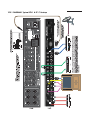
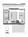
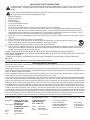
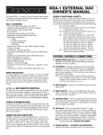
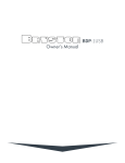
SPV1
VIDEO SWITCHER
OWNER’S MANUAL
GENERAL INFORMATION
Thank you for choosing a Bryston
product. We would welcome any comments or suggestions you may have
regarding the operation of your video
switcher. We consider our customer to
be Bryston’s most important resource
and your opinion is very much appreciated. In the unlikely event you have
a problem with your unit and must
return it for service please keep the
original box and all packaging material.
The Bryston SPV-1 is a high quality,
multi-path, video switcher intended to
be used in combination with the
Bryston SP1.7 surround processor or
as a stand alone video switcher.
SETUP RECOMMENDATIONS
Make sure the power switch on the
rear panel of the video switcher is in
the off position until all connections
are made. Plug the power cord into the
IEC power inlet on the rear panel of
the SPV-1, and plug the male end of
the power cord into a wall outlet.
If using the SPV-1 with the Bryston
SP1.7 connect the RS-232 cable
(straight through with DB9 male connectors at one end and a 1/8” 3-conductor phone plug at the other). If
using it with other control systems
(AMX, Crestron etc.) then a straight
through DB9-male to DB9-female
cable may be required as well.
We recommend placing the SPV-1
beneath the SP1.7 Surround Processor
for ease of connection and performance optimization. The RS-232 cable
should be no longer than 10 feet (3
meters) to minimize communication
errors.
DESCRIPTION
The Bryston SPV-1 Video Switcher
offers six composite video inputs, six
S-video and two component video
inputs. Each set constitutes an isolated
switching path. This feature allows for
the parallel connection of the composite video and S-video with both outputs active. This is helpful for connecting to composite video recording
devices such as (older) VCRs.
Outputs include main (monitor)
for composite, S-video and component
as well as record outputs for composite and S-video. The main outputs
have on-screen display (OSD) capabil-
ity when used in combination with the
Bryston SP1.7 surround processor or
any other RS-232 control system.
On-screen display (OSD) allows
setup and start up information from
the SP1.7 to be displayed on your
video monitor. OSD is only available
when using the RS-232 control method
(see On-Screen Display notes in the
Front Panel Control and Indicators section).
Infra-red (IR) control is also
offered. The functions are accessed by
the SP1.7 remote control or by Pronto
codes available from Bryston.
FRONT PANEL CONTROL & INDICATORS
POWER BUTTON:
Pressing the front panel power button
takes the unit out of stand-by mode
and powers up the SPV-1. If the unit is
already powered-up, then pressing the
power button will power the unit down.
If the power LED does not illuminate,
check that the rear panel power switch
(on the power inlet module) is in the
“ON” (“1”) position.
The LED will change colour as follows:
LED
Output
off
inactive
green
composite
red
S-video
amber
component
SOURCE BUTTONS:
Pressing one of the source buttons will
switch the appropriate composite and
S-video inputs to the Main Outputs.
The LED will be green to indicate the
selected video path for the main outputs. Component input selection is
accomplished using the C1 and C2
selector buttons for component inputs
1 and 2 respectively.
RECORD/ZONE BUTTON:
Pressing this button will indicate the
selected record source being routed to
the record outputs. The record LED
and Source LED will turn red. When
the Record/Zone LED is red, any
source (TV, DVD, VCR, etc.) can be
selected for recording using the source
buttons.
N.B. the record path of the SPV-1 is
separate from the monitor path allowing you to record one source while
monitoring a different source.
OSD (On-Screen-Display):
Pressing the OSD button will change
the OSD assignment between composite, S-video and component, sequence.
To save OSD settings for each type of
input, press the SAVE button on the
remove control.
USING THE BRYSTON SPV-1 WITH THE BRYSTON SP1.7
The combination of the Bryston SP1.7
Surround Processor and the SPV-1
Video Switcher provides for totally
seamless integration of all audio and
video functions.
The Bryston SP1.7 (units manufactured after October 2002) contains all the
RS-232 codes to simultaneously control the switching functions of the SPV1. When the SP1.7 is powered up an
RS-232 command will also power up
the SPV-1. When an input is selected
on the SP1.7 (manually or remotely) it
sends a message to the SPV-1 to
switch the corresponding inputs to the
main and record outputs simultaneously. The audio path on the SP1.7
does not allow a separate record path.
It is not possible to listen to one source
while recording another.
If On-Screen Display (OSD) is
desired, this can be toggled on or off
by pressing the OSD button on the
SP1.7 remote control. The OSD messages will be sent from the SP1.7 to
the SPV-1 and displayed on the video
monitor. OSD messages are displayed
when changing inputs, changing
mode, changing volume, or while
using the setup menus.
IMPORTANT NOTES:
1.
2.
3.
4.
5.
6.
The Component 1 input on the SPV1 will be active when TV/SAT, CD, or VCR
is selected on the Bryston SP1.7 Preamp/Processor *
The Component 2 input on the SPV1 will be active when DVD, AUX, or TAPE
is selected on the Bryston SP1.7 Preamp/Processor *
When using Progressive Scan, De-Interlaced, or HDTV signals turn off the
OSD feature. The Hi-Definition signal will still be passed to the Component
Output but On Screen display (OSD) will not be available. If OSD is active
Hi-Definition signals will not be passed to the Component output.
When OSD is active the SP1.7's front panel LCD menu will operate slower
than normal and appear on screen. Turn off OSD if normal front panel menu
operation is required.
When not using the OSD it is recommended that it be turned off to ensure
optimum picture quality.
The On-Screen Display (OSD) settings can be saved for each input by selecting which OSD mode you wish (Composite, Component, S-video or Off) and
hitting SAVE on the SP1.7 remote control. *
* If the SP1.7 Preamp/Processor is used in combination with SPV1 Video Switcher
SPECIFICATIONS:
Composite & S-Video Bandwidth - 60 MHz
Component Video Bandwidth - 150 MHz
Inputs: 6 Composite, 6 S-Video, 2- Component, 1 serial data
Input Impedance: 75 ohms
Output Impedance: 75 ohms
S/N ratio: >80dB
Monitor Outputs: 1 Composite, 1- S-Video and 1 Component
Record Outputs : (no OSD) 1 Composite, 1- S-Video
Control Options: IR , RS232 and Front Panel.
Dimensions: (HWD) - 1.75 inches x 17 inches x 12 inches.
Weight: 10 Lbs
SPV-1 DIAGRAMS: Front and Rear Panel Legends
SPV-1 DIAGRAMS: Typical SPV-1 & SP1.7 Hookup
SPV-1 DIAGRAMS: Upgrading SP1.7 Surround Processors
Older SP1.7 Surround Processors made before November 2002 may require a firmware
upgrade to enable the serial data control link between the SP1.7 and the SPV-1 Video
Switcher. If you experience any difficulties in getting your SPV-1 working properly with
your SP1.7, please contact either your dealer or the factory. SP1.7 firmware revision
41A (or greater) is required.
If you need to install upgraded firmware (Revision
41a or greater) in your SP1.7 Surround Processor,
the SP1.7’s EPROM (Erasable-Programmable Read
Only Memory) chip will have to be replaced. This
chip is located on the SP1.7’s MicroController board
(named “SP1-uC”). The EPROM chip is shown in
black in the diagram above. Detailed installation
instructions will be included with your firmware
upgrade kit. When ordering, please ask for a free
Chip Extractor tool if you don’t already have one.
This simple tool (see illustration to the left) will
make the task of replacing the EPROM simpler and
safer.
IMPORTANT SAFETY INSTRUCTIONS
The lightning flash with arrowhead symbol within an equilateral triangle, is intended to alert the user to the presence of un-insulated
“dangerous voltage “ within the product’s enclosure that may be of sufficient magnitude to constitute a risk of electric shock to
persons.
The exclamation point within an equilateral triangle is intended to alert the user to the presence of important operating and maintenance
(servicing) instructions in the literature accompanying the product.
1. Read these instructions.
2. Keep these instructions.
3. Heed all warnings.
4. Follow all instructions.
5. Do not use this apparatus near water.
6. Clean only with dry cloth.
7.Do not block any ventilation openings. Install in accordance with the manufacturer’s instructions.
8.Do not install near any heat sources such as radiators, heat registers, stoves, or other apparatus (including amplifiers) that produce heat.
9.Do not defeat the safety purpose of the polarized or grounding-type plug. A polarized plug has two blades with one wider than the other. A
grounding type plug has two blades and a third grounding prong. The wide blade or the third prong are provided for your safety. If the provided plug does not fit into your outlet, consult an electrician for replacement of the obsolete outlet.
10.Protect the power cord from being walked on or pinched particularly at plugs, convenience receptacles, and the point where they exit from the
apparatus.
11. Only use attachments/accessories specified by the manufacturer.
12.Use only with the cart, stand, tripod, bracket, or table specified by the manufacturer, or sold with the apparatus. When a cart is
used use caution when moving the cart/apparatus combination to avoid injury from tip-over.
13.Unplug this apparatus during lightning storms or when unused for long periods of time.
14.Refer all servicing to qualified service personnel. Servicing is required when the apparatus has been damaged in any way, such as powersupply cord or plug is damaged, liquid has been spilled or objects have fallen into the apparatus, the apparatus has been exposed to rain or
moisture, does not operate normally, or has been dropped.
WARNING: TO REDUCE THE RISK OF FIRE OR ELECTRIC SHOCK, DO NOT EXPOSE THIS APPARATUS TO RAIN OR MOISTURE.
DO NOT EXPOSE THIS EQUIPMENT TO DRIPPING OR SPLASHING AND ENSURE THAT NO OBJECTS FILLED WITH LIQUIDS, SUCH AS VASES, ARE
PLACED ON THE EQUIPMENT.
TO COMPLETELY DISCONNECT THIS EQUIPMENT FROM THE AC MAINS, DISCONNECT THE POWER SUPPLY CORD PLUG FROM THE AC
RECEPTACLE.
THE MAINS PLUG OF THE POWER SUPPLY CORD SHALL REMAIN READILY OPERABLE.
BRYSTON LIMITED WARRANTY
Bryston analog audio circuits are warranted to be free from manufacturing defects for twenty (20) years from the original date of manufacture. The
warranty includes parts and labour.
Bryston Digital circuits and cables are warranted for five years from the original date of manufacture. The warranty includes parts and labour.
Bryston products having motorized moving parts, excluding motorized volume controls, are warranted for three years from the original date of manufacture. The warranty includes parts and labour.
Bryston will remedy the problem by repair or replacement, as we deem necessary, to restore the product to full performance. Bryston will pay shipping costs one way (usually the return portion) during the first three years of warranty coverage.
In the event of a defect or malfunction, contact Bryston’s repair centers for return authorization. Products must be returned using original packaging
material only. Packing material may be purchased from Bryston if necessary. This warranty is considered void if the defect, malfunction or failure of the
product or any component part was caused by damage (not resulting from a defect or malfunction) or abuse while in the possession of the customer.
Tampering by persons other than factory authorized service personnel or failure to fully comply with Bryston operating instructions voids the warranty.
This warranty gives you specific legal rights and you may also have other rights which may vary from province to province and country to country.
As of 2006-02-22 Bryston will only warranty Bryston products purchased through authorized Bryston dealers. Bryston products with a date code
of 0608 or higher (date code format is “yyww”, where “yy” is the two least significant digits of the year and “ww” is the week of the year) must be
accompanied by a copy of the bill-of-sale from a Bryston authorized dealer to qualify for warranty service. The warranty is transferable from the original
owner to a subsequent owner as long as a copy of the bill-of-sale from the original authorized Bryston dealer accompanies the re-sale. The copy of the
bill of sale to any subsequent owner need ONLY include the Name of the Bryston Authorized Dealer and the Model and Serial number of the Bryston
product The warranty will only be honored in the country of the original purchase unless otherwise pre-authorized by Bryston.
BRYSTON SERVICE in CANADA:
BRYSTON SERVICE in the USA:
BRYSTON SERVICE outside Canada and the USA:
Postal address: P.O. BOX 2170, Stn. Main
PETERBOROUGH, ONTARIO
CANADA K9J 7Y4
Courier address: 677 NEAL DRIVE
PETERBOROUGH, ONTARIO
CANADA K9J 6X7
79 COVENTRY ST., Suite 5
NEWPORT, VERMONT
U.S.A. 05855-2100
contact your local distributor or
PHONE:
FAX:
E-mail:
705-742-5325
705-742-0882
[email protected]
PHONE:
FAX: E-mail:
802-334-1201
802-334-6658
[email protected]
SPV1_MANUAL_20060324
CHECK OUR WEB SITE: www.bryston.ca
E-MAIL BRYSTON DIRECTLY: [email protected]
FAX BRYSTON DIRECTLY: 01-705-742-0882
PHONE BRYSTON DIRECTLY: 01-705-742-5325