1
OWNER ’S OPERATING MANUAL
CW-43MC
CW-50MC
with
Flat Panel Display Monitor
CONTENTS
Introduction . . . . . . . . . . . . . . . . . . . . . . . . . . . . . . . . . . . . . . . . . . . . . . . . . . . . . . . . . . . 2
Features and Benefits . . . . . . . . . . . . . . . . . . . . . . . . . . . . . . . . . . . . . . . . . . . . . . . . . 2
High Altitude Operation . . . . . . . . . . . . . . . . . . . . . . . . . . . . . . . . . . . . . . . . . . . . . . . 2
Warnings and Safety Precautions . . . . . . . . . . . . . . . . . . . . . . . . . . . . . . . . . . . . . . . . . 3
Warning . . . . . . . . . . . . . . . . . . . . . . . . . . . . . . . . . . . . . . . . . . . . . . . . . . . . . . . . . . . . 4
Safety Tips . . . . . . . . . . . . . . . . . . . . . . . . . . . . . . . . . . . . . . . . . . . . . . . . . . . . . . . . . . 4
Limited Warranty . . . . . . . . . . . . . . . . . . . . . . . . . . . . . . . . . . . . . . . . . . . . . . . . . . . . . . 5
Operation . . . . . . . . . . . . . . . . . . . . . . . . . . . . . . . . . . . . . . . . . . . . . . . . . . . . . . . . . . . . 7
General Overview . . . . . . . . . . . . . . . . . . . . . . . . . . . . . . . . . . . . . . . . . . . . . . . . . . . . 7
Quick Setup Instructions . . . . . . . . . . . . . . . . . . . . . . . . . . . . . . . . . . . . . . . . . . . . . . . 7
Inputs and Controls . . . . . . . . . . . . . . . . . . . . . . . . . . . . . . . . . . . . . . . . . . . . . . . . . . . . 8
Connecting the Plasma Display . . . . . . . . . . . . . . . . . . . . . . . . . . . . . . . . . . . . . . . . . . . 10
Front Panel . . . . . . . . . . . . . . . . . . . . . . . . . . . . . . . . . . . . . . . . . . . . . . . . . . . . . . . . . . . 11
Remote Control Description . . . . . . . . . . . . . . . . . . . . . . . . . . . . . . . . . . . . . . . . . . . . . 12
Menus for Video NTSC, PAL or Digital 480p and HDTV . . . . . . . . . . . . . . . . . . . . . 13
OSD Menus . . . . . . . . . . . . . . . . . . . . . . . . . . . . . . . . . . . . . . . . . . . . . . . . . . . . . . . . . 13
Menus for PC/HDTV-I D-Sub Input . . . . . . . . . . . . . . . . . . . . . . . . . . . . . . . . . . . . . . . 15
OSD Menus . . . . . . . . . . . . . . . . . . . . . . . . . . . . . . . . . . . . . . . . . . . . . . . . . . . . . . . . . 15
INSTALLER Menus for Video NTSC, PAL or Digital 480p and HDTV . . . . . . . . . 16
INSTALLER ADJUST Menus . . . . . . . . . . . . . . . . . . . . . . . . . . . . . . . . . . . . . . . . . . 16
INSTALLER Menus for Video NTSC, PAL or ATSC . . . . . . . . . . . . . . . . . . . . . . . . . 17
INSTALLER ADJUST Menus . . . . . . . . . . . . . . . . . . . . . . . . . . . . . . . . . . . . . . . . . . 17
Aspect Ratios . . . . . . . . . . . . . . . . . . . . . . . . . . . . . . . . . . . . . . . . . . . . . . . . . . . . . . . . . . 18
RS-232C Adjustment Mode . . . . . . . . . . . . . . . . . . . . . . . . . . . . . . . . . . . . . . . . . . . . . . 19
Interface . . . . . . . . . . . . . . . . . . . . . . . . . . . . . . . . . . . . . . . . . . . . . . . . . . . . . . . . . . . . 20
RS-232C Commands . . . . . . . . . . . . . . . . . . . . . . . . . . . . . . . . . . . . . . . . . . . . . . . . . . 22
GET Commands . . . . . . . . . . . . . . . . . . . . . . . . . . . . . . . . . . . . . . . . . . . . . . . . . . . . . . 28
Dimensions . . . . . . . . . . . . . . . . . . . . . . . . . . . . . . . . . . . . . . . . . . . . . . . . . . . . . . . . . . . . 32
CW-43MC . . . . . . . . . . . . . . . . . . . . . . . . . . . . . . . . . . . . . . . . . . . . . . . . . . . . . . . . . . 32
CW-50MC . . . . . . . . . . . . . . . . . . . . . . . . . . . . . . . . . . . . . . . . . . . . . . . . . . . . . . . . . . 33
Specifications . . . . . . . . . . . . . . . . . . . . . . . . . . . . . . . . . . . . . . . . . . . . . . . . . . . . . . . . . . 34
1
INTRODUCTION
Congratulations on your purchase of the CW-43MC/CW-50MC Plasma display! Your CW-43MC/CW-50MC will provide
you with many years of enjoyment no other plasma can match. It is compatible with current NTSC and PAL systems, as
well as DTV standards. And since the display is the 16:9 aspect ratio, DVD widescreen movies and Digital Television will
look the way they were meant to look- in the widescreen format. Plasma technology is proving to be the most flexible and
reliable type of display device currently available. The CW-43MC/CW-50MC is considered a fixed-pixel device, like an
LCD or DLP™ projector. LCD and DLP™ projectors require a light bulb to create the light, and the light is then reflected
off of the tiny DMD™ mirrors in a DLP™, or passed through LCD panels in LCD projectors. The plasma, however, uses
micro gas-filled cells to create the pixel images, which generate their own light. This is very advantageous, as this allows
the plasma display to be used in any type of situation, from dark theaters to light-filled rooms. And it also makes the plasma
the most maintenance-free type of display device - no bulbs or CRTs to change, ever!
This manual will explain how to use your CW-43MC/CW-50MC plasma display, as well as its features, benefits and other
important information. Please ensure you read this manual carefully before using your CW-43MC/CW-50MC, especially
the safety precautions!
Features and Benefits
• 1024 x 768 (CW-43MC) and 1280 x 768 (CW-50MC) HDTV resolution with 16:9 aspect ratio
• Designed for custom automation control with RS-232C and IR interfaces
• Accepts all DTV formats
• Multiple aspect ratio control
• Less than 4 1/2 inches thin
• Digital 480P, 720P, 1080i input via DVI w/HDCP
• Advanced VivixII™ modular controller with orthogonal processing
High Altitude Operation
Due to the design of all plasma glass panels made by every manufacturer, and the interaction between ambient air pressure
and the plasma gases contained inside of the panel, reliable operation of your plasma display cannot be assured during
operation at certain high altitude locations.
We have found this plasma monitor to be reliable at altitudes of up to 5000 MSL (mean sea level). At elevations higher
than this, each panel may react differently, depending upon the altitude, air pressure, humidity and other meteorological
factors.
For this reason, Runco International makes no warrants or claims as to the reliable operation of this plasma display monitor
product at altitudes greater than 5000 feet above sea level.
If you are planning to operate a plasma monitor at a location above 5000 feet, please contact Runco technical support for
further information.
2
WARNINGS AND SAFETY PRECAUTIONS
CAUTION:
To turn off main power, be sure to remove the plugs from power outlets. The power outlet socket should be installed as
near to the equipment as possible, and should be easily accessible.
REMARQUE:
Pour mettre l’appareil hors circut, s’assurer de retirer la fiche de la prise d’alimentation. La prise d’alimentation doit être
installé aussi proche que possible de l’appareil et doit être facile d’ accès.
WARNING
TO PREVENT FIRE OR SHOCK HAZARDS, DO NOT EXPOSE THIS UNIT TO RAIN OR MOISTURE. ALSO
DO NOT USE THIS UNIT’S POLARIZED PLUG WITH AN EXTENSION CORD RECEPTACLE OR OTHER
OUTLETS, UNLESS THE PRONGS CAN BE FULLY INSERTED. REFRAIN FROM OPENING THE CABINET
AS THERE ARE HIGH-VOLTAGE COMPONENTS INSIDE. REFER SERVICING TO QUALIFIED SERVICE
PERSONNEL.
AVERTISSEMENT
POUR EVITER UN FEU OU UN RISQUE D’ELECTROCUTION NE PAS EXPOSER CET ENSEMBLE A LA PLUIE
OU A L’HUMIDITE; DE MEME, NE PAS BRANCHER LA PRISE POLAIRE AVEC UNE RALLONGE A MOINS QUE
LES DENTS DE LA PREMIERE NE S’Y INSERENT PLEINEMENT.
EVITER D’OUVRIR LE COFFRET CAR IL Y A, A L’INTERIEUR, DES COMPOSANTS SOUMIS A UNE HAUTETENSION; POUR LES REPARATIONS, S’ADRESSER A UN PERSONNEL QUALIFIE.
3
WARNING
This equipment has been tested and found to comply with the limits for a Class ‘B’ digital device, pursuant to Part 15 of the
FCC Rules. These limits are designed to provide reasonable protection against harmful interference when the equipment is
operated in a commercial environment. This equipment generates, uses, and can radiate radio frequency energy and, if not
installed and used in accordance with the Installation Manual, may cause harmful interference to radio communications.
Operation of this equipment in a residential area may cause harmful interference, in which case, the user will be required
to correct the interference at his own expense.
DOC compliance Notice
This Class B digital apparatus meets all requirements of the Canadian Interference-Causing Equipment Regulations.
DOC avis de conformation
Cet appareil numérique de la classe B respecte toutes les exigences du Réglement sur le Matériel D’interférence du Canada.
SAFETY TIPS
Please read and follow the safety precautions listed below to ensure the equipment is free from damage, and to ensure
that no injury will occur as a result of improper use.
· Do not insert any object, especially metal or liquids, into the Plasma display.
· Do not place any objects containing water or any other liquid on top of the Plasma display.
· Do not place the units in direct sunlight, near heaters or in extremely dusty or humid locations.
· Do not install this system outdoors or otherwise exposed to the elements.
· Do not place heavy objects on top of the Plasma display.
· If the power cord is damaged or frayed in any way, electrical shock and/or fire may result. Do not place objects on the
power cord, and keep the cord away from heat-emitting devices. Should the power cord become damaged in any way,
please contact your Runco Dealer for a replacement cord.
· Do not remove the cover of the Plasma display for any reason. If any problems arise with the unit, please contact a Runco
Dealer or Runco International for service. Removing the covers will void the warranty.
4
LIMITED WARRANTY
Congratulations on your purchase of a Runco International video product and welcome to the Runco family! We believe
Runco produces “The World’s Finest Home Theater Products”. With proper installation, setup and care, you should enjoy
many years of unparalleled video performance.
This is a LIMITED WARRANTY as defined in the Magnuson-Moss Warranty Act. Please read it carefully and retain it
with your other important documents.
WHAT IS COVERED UNDER THE TERMS OF THIS LIMITED WARRANTY:
SERVICE LABOR: Runco will pay for service labor by a Runco Authorized Service Center when needed as a result of
a manufacturing defect for a period of three (3) years from the effective date of delivery to the end user (excluding the
plasma glass panel).
PARTS: (Not including plasma glass panel) Runco will provide new or rebuilt replacement parts for the parts that fail due to
defects in materials or workmanship for a period of three (3) years from the effective date of delivery to the end user. Such
replacement parts are then subsequently warranted for the remaining portion (if any) of the original warranty period.
PLASMA GLASS PANEL: Runco will pay for service labor by a Runco Authorized Service Center when needed as a result
of a manufacturing defect for a period of one (1) year from the effective date of delivery to the end user. In addition, Runco
will provide new or rebuilt replacement parts for the parts that fail due to defects in materials or workmanship for a period
of one (1) year from the effective date of delivery to the end user. Such replacement parts are then subsequently warranted
for the remaining portion (if any) of the original warranty period.
WHAT IS NOT COVERED UNDER THE TERMS OF THIS LIMITED WARRANTY:
Image burn-in on plasma display panels are specifically excluded from coverage under this Limited Warranty. Image burnin is the result of misuse of the product and therefore cannot be repaired under the terms of this Limited Warranty.
TO AVOID IMAGE BURN-IN:
Please ensure that still images are left on your plasma display panel for no more than a few minutes. Also ensure that images
displayed in the 4:3 aspect ratio mode (black or gray stripes, but no picture information is present on the left and right edges
of the screen) are used as infrequently as possible. This will prevent permanent image burns on your plasma display panel,
which can be seen permanently under certain conditions once burn-in has occurred.
The types of images to avoid include video games, still images and computer screens with stationary tool bars and icons.
(This is why computers are equipped with screen savers – to prevent still images from burning into the monitor’s phosphors
after being displayed continuously for an extended period of time).
Normal viewing material such as television/satellite broadcasts, videotape or DVDs (not put into pause for extended periods
of time) will not cause damage to your display under normal conditions. Many DVD players are also equipped with screen
savers for this reason.
IMPORTANT: RUNCO IS NOT RESPONSIBLE FOR IMAGE BURNS ON ANY DISPLAY.
PLEASE EXERCISE CAUTION WHEN USING A 4:3 IMAGE ON A 16:9 SCREEN.
5
This Limited Warranty only covers failure due to defects in materials and workmanship that occur during normal use
and does not cover normal maintenance. This Limited Warranty does not cover cabinets or any appearance items; failure
resulting from accident, misuse, abuse, neglect, mishandling, misapplication, faulty or improper installation or setup
adjustments; improper maintenance, alteration, improper use of any input signal; damage due to lightning or power line
surges, spikes and brownouts; damage that occurs during shipping or transit; or damage that is attributed to acts of God. In
the case of remote control units, damage resulting from leaking, old, damaged or improper batteries is also excluded from
coverage under this Limited Warranty.
CAUTION: THIS LIMITED WARRANTY ONLY COVERS RUNCO PRODUCTS PURCHASED FROM RUNCO
AUTHORIZED DEALERS. ALL OTHER PRODUCTS ARE SPECIFICALLY EXCLUDED FROM COVERAGE
UNDER THIS LIMITED WARRANTY. MOREOVER, DAMAGE RESULTING DIRECTLY OR INDIRECTLY FROM
IMPROPER INSTALLATION OR SETUP IS SPECIFICALLY EXCLUDED FROM COVERAGE UNDER THIS
LIMITED WARRANTY.
RIGHTS, LIMITS AND EXCLUSIONS:
Runco limits its obligations under any implied warranties under state laws to a period not to exceed the warranty period.
There are no express warranties. Runco also excludes any obligation on its part for incidental or consequential damages
related to the failure of this product to function properly. Some states do not allow limitations on how long an implied
warranty lasts, and some states do not allow the exclusion or limitation of incidental or consequential damages. So the
above limitations or exclusions may not apply to you. This warranty gives you specific legal rights, and you may also have
other rights that vary from state to state.
EFFECTIVE WARRANTY DATE:
This warranty begins on the effective date of delivery to the end user. For your convenience, keep the original bill of sale
as evidence of the purchase date.
IMPORTANT: WARRANTY REGISTRATION:
Please fill out and mail your warranty registration card. It is imperative that Runco knows how to reach you promptly if we
should discover a safety problem or product update for which you must be notified.
CONTACT A RUNCO AUTHORIZED SERVICE CENTER TO OBTAIN SERVICE:
Repairs made under the terms of this Limited Warranty covering your Runco video product will be performed at the
location of the product, during usual working hours, providing location of product is within normal operating distance
from a Runco Authorized Service Center. In some instances it may be necessary for the product to be returned to the
Runco factory for repairs. If, solely in Runco’s judgment, location of product to be repaired is beyond normal operating
distance of the closest Runco Authorized Service Center, or the repair requires the unit be returned to the Runco factory, it
is the owner’s responsibility to arrange for shipment of the product for repair. These arrangements must be made through
the selling Runco Dealer. If this is not possible, contact Runco directly for a Return Authorization number and shipping
instructions. Runco will return product transportation prepaid in the United States, unless no product defect is discovered.
In that instance, shipping costs will be the responsibility of the owner.
ADDITIONAL INFORMATION:
To locate the name and address of the nearest Runco authorized service location, or for additional information about this
Limited Warranty, please call or write:
RUNCO INTERNATIONAL
Attn: Customer Service Department
2900 Faber Street
Union City, CA 94587
Ph (510) 324-7777
Fax (510) 324-9300
Toll Free 1-800-23-RUNCO
6
OPERATION
General Overview
The Runco CW-43MC and CW-50MC are standalone flat panel plasma displays with outboard VivixII™ video processing.
With 1024 x 768 native resolution for the CW-43MC and 1280 x 768 native resolution for the CW-50MC, both are capable
of imaging native HDTV. The CW-43MC and CW-50MC include a DVI digital input as well as standard analog inputs.
QUICK SETUP Instructions
1. Install the Plasma display. This could be either table mount or wall mount configurations.
2. Connect the video interconnections between the output of any media source (such as DVD players or satellite receivers,
or a DTV or computer source) and the input of the plasma display.
3. Plug in AC power to the Plasma display, and turn the plasma on.
4. Select the desired source on the remote control and the source should now be displayed on the plasma. If it is not, please
check the wiring.
5. Clear the screen of any OSD menus.
6. From the remote, to access the INSTALLER ADJUST menu use a small paper clip or thin pen and press the ‘SVC’
button through the pin hole. (see Page 12 for more instructions)
7. Use the arrow ▲ UP and ▼ DOWN keys to select the adjustments options within each menu
• Press “SET” to select the adjustment option
• Press “SET” again to return to the INSTALLER ADJUST menu
NOTE: pressing the ‘MENU’ button will return back to the user mode, if nothing is done the plasma will return to
the user mode within 3 minutes.
• Press the ‘Menu’ button to save the settings and then return to the user mode.
7
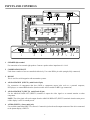
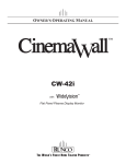
INPUTS AND CONTROLS
���
�����
��
�����
�������
�� ���
������� �
���
��
��
��
�������� �
����������
��
������
�
�������
�
�
� ���
�������������
�����
��������������������
������� �
�����������
��
��������������������
�
��������������
�����
�����
������������
�����
������
�����
������
�����
�
�
�������
��������������������������������������������������������������������
����������
1
SPEAKER (R) terminal
For connection of an external right speaker. Connect a speaker whose impedance is 8 -16 Ω.
2
COMBINATION IN/OUT
Used when a number of sets are controlled collectively. Use a mini DIN 6 pin cable (straight, fully connected).
3
RS-232C
This is used for serial integration with automation systems.
4
ANALOG RGB IN (INPUT1) (mini D-sub 15 pin)
For connection of components that have RGB or component output jacks such as a personal computer,
DVD player, or external RGB decoder. (break out cable will be needed for BNC type connection)
5
ANALOG RGB OUT (INPUT1) (mini D-sub 15 pin)
Use the ANALOG RGB OUT (INPUT1) terminal to output the video signal to an external monitor or other
component.
NOTE: The video signal will not be output from the ANALOG RGB OUT (INPUT1) terminal when the main power
of this display is off or in standby mode.
6
AUDIO (INPUT1) (Stereo mini jack)
Use to obtain sound when INPUT1 is selected. Connect this jack to the audio output connector of the device connected
to the plasma display’s INPUT1.
8
7
DIGITAL RGB (INPUT2) (DVI-D jack-non HDCP)
Use to connect a computer resolution only. (VESA standard)
8
AUDIO (INPUT2) (Stereo mini jack)
Used to obtain sound when INPUT1, INPUT2 is selected. Connect this jack to the audio output connector of the device
connected to the plasma display’s INPUT1 or INPUT2.
9
AUDIO (OUTPUT) (Stereo mini jack)
Used to output the audio of the selected source component connected to the plasma display to an AV amplifier or similar
component output can be set to variable or fixed.
10 MAIN POWER switch
Used to switch the main power or the main unit on and off.
11 AC IN
A power cable is furnished with the main unit. Connect one end of the power cable to this connector and the other
end to a standard AC power source.
12 SPEAKER (L) terminal
For connection of an external left speaker. Connect a speaker that has an impedance of 8 -16 Ω.
13 INPUT5 (DVI Jack-HDCP COMPLIANT)
The DVI input will process digital video 480p, 720p and 1080i signals (computer rates are not recommended).
14 AUDIO IN 3, 4 and 5
1/8” Mini stereo jack used for external audio input. Used for Audio Inputs when desired with a video source
connected to video input 3, 4 and 5.
15 INPUT4
Interlaced component (480i) input.
16 INPUT3 (S-Video / Composite Video Input)
Selectable with center push button.
9
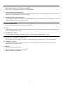
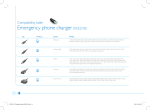
CONNECTING THE PLASMA DISPLAY
Modular Controller Card - Input Connections
Plasma Rear View
DVI
Component
S-Video
Composite
Push Button
INPUT 5
DVI SOURCE INPUT (WITH HDCP DECRYPTION): (Digital 480P, 720P, 1080i): Input for set top box or PC with
DVI digital output.
INPUT 4
COMPONENT INPUT: Component video is the best type of signal that can be used. The most common sources
that use component outputs are DVD players, and it is highly recommended that component be used when
possible. Component video goes one step beyond S-Video in picture quality; chroma (color) information is more resolved
and the overall picture appears more well-defined.
INPUT 3
S-VIDEO INPUT: S-Video is the second-best type of signal that can be used, but is MUCH better than Composite
video. Using such sources as Satellite receivers, high-quality VCRs and DVD players (with no component
output) will produce a MUCH cleaner and sharper signal than composite.
S-VIDEO/COMPOSITE SELECTION PUSH BUTTON: This push button toggles between S-Video and Composite
Video when using Input 3. Both S-Video and Composite Video cannot be active simultaneously.
COMPOSITE VIDEO INPUT: Composite video is the most common type of signal used, but is also the lowest in picture
quality. Many sources have outputs that are limited to composite video, such as some VCR’s and camcorders; others such
as Laser Disc players actually produce slightly better results when using composite video.
10
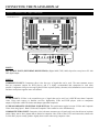
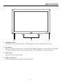
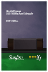
FRONT PANEL
12
3
4
1. STANDBY Indicator
This indicator is red during standby mode. The flashing pattern is also used to indicate error messages.
2. ON Indicator
Lights green when the plasma display is operating. When flashing, the indicator is used to indicate error messages.
The indicator flashes green once every one second when the (AUTO POWER OFF) function is operating.
3. Display Stand
Optional accessory for tabletop mount.
4. Remote Control Sensor
Receives the IR (infra-red) commands from the remote control.
11
REMOTE CONTROL DESCRIPTION
Plasma Remote Control
A. ASPECT RATIO
Press to change the aspect ratio or geometry of
the image. Different resolutions will allow for
different aspect ratios.
B
A
B. RGB SETUP
When entering a computer-type (VESA) signal,
press this to automatically center and resize the
image.
D
G
C. POWER
Press this to cycle the monitor between on and
standby.
ASPECT
RATIO
POWER
RGB
SETUP
C
PC/HDTV-1
HDTV-2
1
2
SDTV-1
SDTV-2
3
4
INFO
F
DIGITAL IN
I
H
T (svc)*
MENU
D. PC/HDTV-1
Selects the 15-pin D-sub input for computer-type
(VESA) signals or HDTV signals.
MAGNIFY
K
J
E. HDTV-2
Selects the computer DVI input. (Input2)
F. INFO
While video is being displayed, this will bring up
timing information and input signal.
L, M, N, O
SET
P
G. SDTV-1
Selects the first standard definition input, either
S-Video or Composite video based on the toggle
button, on Modular Controller card.
R
MUTE
Q
VOLUME
-
+
S
H. SDTV-2
Selects the second standard definition input, for
interlaced component video input.
I. DIGITAL IN
Selects the digital video from the DVI input. (Input5)
J. MENU
Activate or de-activate the menu.
O. DOWN
Scrolls the highlight bar in the menu down.
K. MAGNIFY
Zooms in on the image, particularly useful for
computer-type (VESA) images.
P. SET
Use for entering a sub-menu when selected by
high light.
L. UP
Scrolls the highlight bar in the menu up.
Q. MUTE
Used to mute the sound system.
M. LEFT
Used for scrolling left, particularly during
adjustment menus.
R. VOLUME Used to reduce the volume of the sound system.
N. RIGHT
Used for scrolling right, particularly during
adjustment menus.
S. VOLUME +
Used to reduce the volume of the sound system.
12
E
T. INSTALLER ADJUST - svc (pin hole)*
Used to access the INSTALLER ADJUST MENU.
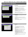
MENUS for VIDEO NTSC, PAL or DIGITAL 480P and HDTV
OSD Menus for Video NTSC, PAL or Digital 480p & HDTV
These menus will appear only when displayed for video.
CINEMAWALL
INPUT 3
SCREEN
PICTURE
CONTRAST
BRIGHTNESS
COLOR
TINT
SHARPNESS
:
:
:
:
:
SET UP
OPTION
0
0
0
0
0
1. PICTURE Tab
The PICTURE menu allows for adjustment of picture
that are unique per input and stored automatically.
• CONTRAST is used to set the white level.
• BRIGHTNESS. is used to set the black level.
• COLOR is used to set color saturation levels.
• TINT allows for balance between red and green levels.
• SHARPNESS is used to enhance high frequency
response in the video signal.
FACTORY
Highlight FACTORY and press SET button for factory
default settings. For current input only.
CINEMAWALL
INPUT3
SCREEN
PICTURE
POSITION
:
SET UP
0/
OPTION
0
2. SCREEN Tab
The SCREEN menu offers adjustments to the position
of the plasma:
• POSITION is used to control movement of the
picture in the Horizontal direction (H), and the Vertical
direction (V).
• DISPLAY RESET causes all the mode settings to be
returned to the factory set default.
DISPLAY RESET
CINEMAWALL
PICTURE
SCREEN
INPUT 3
SET UP
AUTO POWER OFF
COLOR TEMP.
VIDEO NR
MPEG FILTER
CHROMA EE
CINEMA MODE
COLOR SPACE
CLAMP POSITION
SIGNAL
3.
OPTION
: DISABLE
: MIDDLE
: MIDDLE
: LOW
: ON
: OFF
: RGB
: AUTO
: 525p
SET UP Tab
The SET UP menu has adjustment for the initial set up of the
plasma:
• AUTO POWER OFF allows for different light
outputs depending on the situation and environment.
Normally set to disable.
• COLOR TEMP. sets the preset white balance of the
picture.
• VIDEO NR eliminates the artificial noise in the video.
• MPEG FILTER is set for providing noise free video
images when watching a DTV channel or a DVD.
• CHROMA EE is usually set to OFF.
• CINEMA MODE detects film-based sources and
regenerates them for higher picture quality.
• COLOR SPACE is choosing the appropriate color signal.
• CLAMP POSITION detection of the sync signal, usually
set to AUTO.
• SIGNAL displays the frequency and rate of the source.
13
MENUS for VIDEO NTSC, PAL or DIGITAL 480P and HDTV
OSD Menus for Video NTSC, PAL or Digital 480p & HDTV
This menu will appear only when displayed for video.
CINEMAWALL
PICTURE
SCREEN
INPUT 3
SET UP
LANGUAGE
ENERGY MODE
PDP PROTECT
ORBITER
SIDEBAR ADJ.
AUTO SET UP MODE
INPUT PRIORITY
AUDIO OUT LEVEL
:
:
:
:
:
:
:
:
OPTION
ENGLISH
AUTO
OFF
OFF
OFF
OFF
OFF
FIXED
4. OPTION Tab
The OPTION menu has selection for optional
functionality of the panel:
• LANGUAGE allows selection of the desired language
and what language will be set in the memory.
• ENERGY MODE is a selection for intensifying or
deintensifying the picture depending on light conditions.
• PDP PROTECT allows for automatic switching of
the displayed image at regular intervals.
• ORBITER prevents burn-in on static images by
continually shifting the image.
• SIDEBAR ADJ. is used specifically for masking in
4x3 or NTSC signals.
• AUTO SET UP MODE is usually set to OFF.
• INPUT PRIORITY allows for priority to be selected
on a particular input when the unit is powered on/off.
• AUDIO OUT LEVEL sets audio output volume to
fixed or variable output.
14
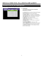
MENUS for PC/HDTV-I D-SUB INPUT
OSD Menus for PC/HDTV-I D-Sub Input
These menus will appear only when displayed for computer.
CINEMAWALL
PICTURE
INPUT 1
SCREEN
CONTRAST
BRIGHTNESS
R. ADJUST
G. ADJUST
B. ADJUST
H. SHARPEN
V. SHARPEN
:
:
:
:
:
:
:
SET UP
OPTION
0
0
0
0
0
0
0
• CONTRAST is used to set the white level.
• BRIGHTNESS is used to set the black level.
• R., G., B. ADJUST can be adjusted to set color
balance.
• H. and V. SHARPEN option allows for adjustment
to improve the detail in the horizontal and vertical
direction independently.
• FACTORY set the back to the default settings.
FACTORY
INPUT1
CINEMAWALL
PICTURE
SCREEN
POSITION
FREQ. ADJ.
PHASE ADJ.
:
:
:
SET UP
0/
0
0
OPTION
0
DISPLAY RESET
INPUT1
CINEMAWALL
PICTURE
SCREEN
SET UP
POWER MANAGEMENT
CLAMP POSITION
SIGNAL
OPTION
: OFF
: MIDDLE
: XGA
INPUT1
CINEMAWALL
PICTURE
SCREEN
1. PICTURE Tab
The Picture menu lists adjustments for computer
input to the plasma:
SET UP
LANGUAGE
ENERGY MODE
PDP PROTECT
ORBITER
SIDEBAR ADJ.
AUTO SET UP MODE
INPUT PRIORITY
AUDIO OUT LEVEL
:
:
:
:
:
:
:
:
OPTION
ENGLISH
AUTO
OFF
OFF
OFF
OFF
OFF
FIXED
2. SCREEN Tab
• POSITION option allows for position shift of the
image.
• FREQ. ADJ. adjusts the frequency to adjust for the
plasma.
• PHASE ADJ. adjusts the image of the picture to
match the screen.
• DISPLAY RESET defaults to the factory settings for
the current input Only.
3. SET UP Tab
• POWER MANAGEMENT shuts-down the plasma
panel when there is no source present.
• CLAMP POSITION normally, leave this setting at
[AUTO] (supported on Input1 only).
• SIGNAL specifies the output to the display.
4. OPTION Tab
• LANGUAGE allows selection of the desired language
and what language will be set in the memory.
• ENERGY MODE selects for an intensified picture
depending on ambient light conditions.
• PDP PROTECT switches the displayed image at
regular intervals.
• ORBITER prevents burn-in on static images.
• SIDEBAR ADJ. for masking in 4x3 or NTSC signals.
• AUTO SET UP MODE a is universal set up mode.
• INPUT PRIORITY allows priority selection of an
input.
15
• AUDIO OUT LEVEL is for audio output.
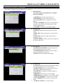
INSTALLER MENUS for VIDEO NTSC, PAL or DIGITAL 480P and HDTV
INSTALLER ADJUST Menus for Video NTSC, PAL or Digital 480p & HDTV
These menus will appear only when displayed for video.
Gaining access to the INSTALLER ADJUST Menu is done by pressing the installer adjust button below SDTV-2 button
(number 4) using a small paperclip (with no menu present). Press menu at any time to exit INSTALLER ADJUST
mode. The adjustments are stored automatically. (see page 12)
INPUT 3
INSTALLER ADJUST
PICTURE
1. PICTURE Tab
Make initial picture adjustments for each input independently.
Refer to the PICTURE description in the OSD for Video
NTSC, PAL Digital 480p and HDTV or PC/HDTV-I, D-Sub
Input Menus for guidance.
WHITE BAL.
SCREEN
CONTRAST
BRIGHTNESS
COLOR
TINT
SHARPNESS
SET UP
OPTION
SET UP
OPTION
SET UP
OPTION
: 128
: 128
: 64
: 30
:
8
INPUT 3
INSTALLER ADJUST
PICTURE
WHITE BAL.
C.DETAIL
C.DETAIL
C.DETAIL
C.DETAIL
C.DETAIL
C.DETAIL
SCREEN
RED
YELLOW
GREEN
CYAN
BLUE
MAGENTA
:
:
:
:
:
:
30
30
30
30
30
30
PICTURE DEFAULT
2. WHITE BAL. Tab
White balance is global for all presets and allows for
configuration of R, B, G levels GAIN and OFFSET. Choose
the middle color temp from the main menu and adjust in this
menu for proper 6500K color temperature. The other presets
in the user menu will be offset by approximately 1000K
higher or lower depending if the preset is cooler or warmer.
3. SCREEN Tab
Adjust positioning of image horizontal and vertical position
for each input if necessary. Screen Default will set back the
factory settings for the current input only.
INPUT 3
INSTALLER ADJUST
PICTURE
WHITE BAL.
SCREEN
R. GAIN
G. GAIN
B. GAIN
R. OFFSET
G. OFFSET
B. OFFSET
:
:
:
:
:
WHITE BAL. DEFAULT
INPUT 3
INSTALLER ADJUST
PICTURE
WHITE BAL.
SCREEN
H SHIFT
V SHIFT
H. SIZE
V. SIZE
SCREEN DEFAULT
16
128
128
128
128
128
SET UP
:
:
:
:
64
64
32
32
OPTION
INSTALLER MENUS for VIDEO NTSC, PAL or ATSC
INSTALLER ADJUST Menus for Video NTSC, PAL or ATSC
These menus will appear only when displayed for video.
4. SETUP Tab
• GAMMA is the relationship between pixel value and
displayed intensity.
• BRT. ENHANCE is used to enhance the black levels.
• SUB VOLUME is used to configure sub-woofer
levels.
5. OPTION Tab
• PDP PROTECTION allows for automatic switching
of the displayed image at regular intervals.
• SCREEN MASK is used for masking of source
material such as 16x9 or 4x3.
• SIDEBAR ADJ. is used specifically for masking in
4x3 or NTSC signals
• 2x2 MODE is used for video wall applications. Up to
4 plasmas can be linked in a 2x2 configuration with no
external processing.
• MIRROR MODE allows for a reflected image to be
shown from the plasma panel.
• BAUD RATE is the RS-232 port connectivity rate.
• ID. NO. SET is used for RS-232C daisy chaining of
the plasma.
• FUNCTION DEFAULT defaults to the factory
settings for all the functions within the input.
INPUT 3
INSTALLER ADJUST
PICTURE
WHITE BAL.
SET UP
SCREEN
GAMMA
BRT. ENHANCE
SUB VOLUME
:
:
:
2.0
OFF
20
INPUT 3
INSTALLER ADJUST
PICTURE
WHITE BAL.
SCREEN
17
OPTION
SET UP
PDP PROTECTION
SCREEN MASK
SIDEBAR ADJ.
2x2 MODE
MIRROR MODE
BAUD RATE
ID NO. SET
FUNCTION DEFAULT
6. OPTION Tab (continued)
• OSD specifies if the On Screen Display is ON or OFF.
• FRONT INDICATOR allows for naming of the
display.
• FAN CONTROL should be set to AUTO for lowest
fan
noise.
• COLOR MODE is used to select between NORMAL
and ISF mode. Once in ISF, values selected in WHITE
BAL. will be saved as settings in ISF. Once NORMAL
is chosen setting are defaulted.
• RUNCO PRO is for adjusting the underscan, setting
markers, enable or disable of color and specifying the
signal type.
• FRC is usually set to Mode1.
:
:
:
:
:
:
OFF
NORMAL
OFF
OFF
9600BPS
01
INPUT 3
INSTALLER ADJUST
PICTURE
OPTION
WHITE BAL.
SCREEN
SET UP
OSD
FRONT INDICATOR
FAN CONTROL
COLOR MODE
RUNCO PRO
FRC
OPTION
: OFF
: AUTO
: NORMAL
: MODE1
ASPECT RATIOS
There are four aspect ratios available that can be selected for video signal inputs.
16:9 Screens:
• ANAMORPHIC: The image is compressed vertically, but anamorphic software will appear properly proportioned.
This is best suited for use with 16:9 DVD’s.
�����������������
• STANDARD 4 x 3: The input signal will be scaled to fit in the center of the 16:9 sceen.
3 units tall
������������
����
4 units wide
• LETTERBOX: The image in the Letterbox mode will be stretched vertically, and the top and bottom portion
‘blanked-off’. This ratio is best suited for DVD, non-anamorphic DVDs and LaserDisc movies.
�������������
����
• VIRTUALWDE: A 4:3 image that is transformed into a 16x9 image to allow the user to watch standard DTV on
their widescreen display.
������������
����
18
RS-232C ADJUSTMENT MODE
Through the unit’s RS-232 terminal, it is possible to use the PC to make various adjustments and settings.
1) About the RS-232C Adjustment Mode
• Adjustments in the RS-232C adjustment mode:
- The adjustments are written to the same memory area as for the installer mode.
2) Display screen in the RS-232C adjustment mode:
• The screen shown below illustrates the set ID number is displayed in the ‘--’ area at the upper left part of the screen.
--
1280X1024@60
ADJUSTMENT
CAUTION:
1) Always enter ID before using RS-232C adjustment mode. Also, include the ID of the set to be targeted for the set to be
controlled or adjusted in the RS-232C command. For details, refer to page 22.
2) There are some RS-232C commands that can be used in normal-operation mode. See page 22.
3) The adjustment data and setting items by RS-232C commands, there are some items that are stored in memory and
some that are not. See page 22. Also, when storing values in last memory, the conditions described in Last Memory,
must have been satisfied.
4) <DIN>/<DIY> (OSD displays disabled/enabled):
Regardless of the setting, the following items can be displayed:
• Menu display (Menu mode and installer adjust mode).
• Warnings before the Auto Power Off or Power Management comes on.
• Warning of high temperature inside the set.
• Display announcing that the FUNCTIONAL LOCK is set; and the FUNCTIONAL LOCK setting display
• Display call (including holding a button down).
5) RS-232C adjustment mode is automatically canceled:
• When the {STANDBY/ON} or {MENU} button is pressed.
6) Before entering the RS-232C adjustment mode, be sure to cancel the installer adjust mode.
7) When performing control using the RS-232C commands, not only do these commands control the input signal, but
they also control the power. If the power is ON when there is no signal, the display continues to have a weak discharge,
could
affect
the of
lifethe
of display.
the display.
that that
could
affect
the life
19
RS-232C ADJUSTMENT MODE
Interface
1) Connector: D-sub 9 pins (male)
2) Pin Layout:
Pin No.
Signal
1
NC (not connected)
2
TxD (Transmit Data)
3
RxD (Receive Data)
4
NC (not connected)
5
GnD
6
NC (not connected)
7
NC (not connected)
8
RTS (Request to Send)
9
NC (not connected)
1
5
6
9
3) Baud Rate: 9600 bps (standard)
(switchable to 1200, 2400, 4800, 19200, 38400 bps)
NOTE: The baud rate of this display should be set to match the baud rate of the computer. Also, when the
RS-232C cable is to be extended over a long distance, a slower baud rate is recommended.
4) Data Format
Start: 1-bit
Data: 8-bit
Parity: 0 (no parity)
Stop: 1-bit
5) Connection
Control PC
(with D25 serial port )
Plasma Display
(CW-43/50MC)
Control PC
(with D9 serial port)
Plasma Display
(CW-43/50MC)
RXD 3
TXD 2
2 TXD
3 RXD
RXD 2
TXD 3
2 TXD
3 RXD
CTS 5
GND 7
8 RTS
5 GND
CTS 8
GND 5
8 RTS
5 GND
* D-sub 9-pin/D-sub 25-pin conversion tables are now available on the. market
Straight Cable
NOTE: Computer manufacturers may not use the same pin assignments. In case of communication difficulties,
check pin functions not just pin numbers.
20
RS-232C ADJUSTMENT MODE
Interface
6) Protocol: From computer to plasmas display:
(1) When sending one command at a time:
STX (02 hex)
ID (2 Byte)
COMMAND (3 Byte or 6 Byte)
ETX (03 hex)
(2) When transmitting commands in batches (up to max. 3 commands are possible): (NOTE)
STX (02 hex)
COMMAND:
ARGUMENT:
ID (2 Byte)
3 Byte
3 Byte
COMMAND (3 Byte)
ARGUMENT (3 Byte)
ETX (03 hex)
(ASCII)
(ASCII)
(3) Echo back
STX (02 hex)
COMMAND (3 Byte or 6 Byte)
ETX (03 hex)
When the recieved command is a numerical direct effect command, numerical data is returned.
STX (02 hex)
COMMAND (3 Byte)
ARGUMENT (3 Byte)
ETX (03 hex)
When the recieved command is non-corresponding command, 'ERR' is returned.
STX (02 hex)
ERR (3 Byte)
ETX (03 hex)
When it is determined that the received command cannot be processed (when PON is received when the power
is already ON, etc.) 'XXX' is returned.
STX (02 hex)
ERR (3 Byte)
ETX (03 hex)
21
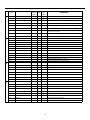
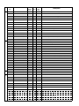
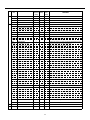
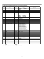
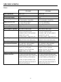
RS-232C Commands
How to read this table:
• RS-232C Adjustment Validity: Indicates whether or not the RS-232 adjustment mode can be used.
• Normal Validity:
Indicates whether or not the normal-operation mode can be used
• Numerical Direct Validity:
When a number (3-digit number) is attached to the end of a command, the command can
directly set that adjustment value.
○ or ●: Valid
No Mark: Invalid
Command
Name
A
B
C
Full Name
NOTE:
RS-232C
Adjustment
Validity
Normal
Validity
● = values not stored in the last memory
Description
Numerical
Direct
Validity
AJN
-
AJY
ADJUST: ON
●
Terminates the RS-232C installer adjustment mode.
AMN
AUDIO MUTING: OFF
AMY
AUDIO MUTING: ON
AST
AUTO SET UP MODE
BHI
B GAIN
○
○
Adjusts BLUE GAIN HIGH-LIGHT.
BLW
B OFFSET
○
○
Adjusts BLUE OFFSET LOW-LIGHT.
BRA
BAUD RATE: #####-232C
●
Displays the current baud rate.
BRAS01
BAUD RATE: 1200-232C
○
Sets the UART setting to 232C (1200bps).
BRAS02
BAUD RATE: 2400-232C
○
Sets the UART setting to 232C (2400bps).
BRAS03
BAUD RATE: 4800-232C
○
Sets the UART setting to 232C (4800bps).
BRAS04
BAUD RATE: 9600-232C
○
Sets the UART setting to 232C (9600bps).
BRAS05
BAUD RATE: 19200-232C
○
Sets the UART setting to 232C (19200bps).
BRAS06
BAUD RATE: 38400-232C
○
BRT
BRIGHTNESS: ***
○
○
Adjusts brightness.
BSL
B SIDEBAR ADJ. LEVEL
○
○
Adjusts BLUE SIDEBAR ADJUST LEVEL.
CFR
FREQ. ADJ.: ***
○
○
Adjusts the clock frequency (PLL frequency).
CGB
C. DETAIL BLUE: ***
○
○
Adjusts color detail BLUE.
CGC
C. DETAIL CYAN: ***
○
○
Adjusts color detail CYAN.
CGG
C. DETAIL GREEN: ***
○
○
Adjusts color detail GREEN.
CGM
C. DETAIL MAGENTA: ***
○
○
Adjusts color detail MAGENTA.
CGR
C. DETAIL RED: ***
○
○
Adjusts color detail RED.
CGY
C. DETAIL YELLOW: ***
○
○
Adjusts color detail YELLOW.
CLS
COLOR SYSTEM: #####
●
Displays the current color system.
CLSS01
COLOR SYSTEM: AUTO
○
Sets the color system to AUTO.
CLSS02
COLOR SYSTEM: NTSC
○
Sets the color system to NTSC.
CLSS03
COLOR SYSTEM: PAL
○
Sets the color system to PAL.
CLSS04
COLOR SYSTEM: SECAM
○
Sets the color system to SECAM.
CLSS05
COLOR SYSTEM: 4.43NTSC
○
Sets the color system to 4.43NTSC.
CLSS06
COLOR SYSTEM: PAL M
○
Sets the color system to PAL M.
CLSS07
COLOR SYSTEM: PAL N
○
CM1
NORMAL
○
○
CM2
ISF
○
○
CNT
CONTRAST: ***
○
COF
COLOR OFF: ********
●
Displays the current COLOR OFF setting.
COFS00
COLOR OFF: DISABLE
○
Disables COLOR OFF.
COFS01
COLOR OFF: ENABLE
○
Enables COLOR OFF.
COL
COLOR: ***
○
○
CPH
PHASE ADJ.: ***
○
○
●
Starts the RS-232C installer adjustment mode.
●
●
Turns audio mute OFF.
●
●
Turns audio mute ON.
○
Executes AUTO SETUP.
Sets the UART setting to 232C (38400bps).
Sets the color system to PAL N.
Sets the Normal color mode.
Sets the ISF color mode (retake).
○
22
Adjusts contrast.
Adjusts the phase (PLL phase).
Command
Name
C
D
E
F
Full Name
RS-232C
Adjustment
Validity
Normal
Validity
Description
Numerical
Direct
Validity
CTP
COLOR TEMP: ********
●
Displays the current COLOR TEMP.
CTPS01
COLOR TEMP.: 1
○
Sets the COLOR TEMP. to LOW (equal to -3000K)
CTPS02
COLOR TEMP.: 2
○
Sets the COLOR TEMP. to MID-LOW (equal to -2000K)
CTPS03
COLOR TEMP.: 3
○
Sets the COLOR TEMP. to MIDDLE (±OK, standard)
CTPS04
COLOR TEMP.: 4
○
Sets the COLOR TEMP. to MID-HIGH (equal to +1000k)
CTPS05
COLOR TEMP.: 5
○
Sets the COLOR TEMP. to HIGH. (equal to +2000K)
CTR
CTI: ###
●
Displays the current color transient improvement setting, to make image
have clearer color contours.
CTRS00
CTI: OFF
○
Sets CTI to OFF.
CTRS01
CTI: ON
○
Sets CTI to ON.
○
○
Turns off the OSD display.
DIY
OSD: ON
○
○
Turns on the OSD display.
DNR
VIDEO NR: #####
●
Displays the current DNR setting.
DNRS00
VIDEO NR: OFF
○
Sets the VIDEO NR to ON.
DNRS01
VIDEO NR: LOW
○
Sets the VIDEO NR to LOW.
DNRS02
VIDEO NR: MIDDLE
○
Sets the VIDEO NR to MIDDLE.
DNRS03
VIDEO NR: HIGH
○
Sets the VIDEO NR to HIGH.
DOF
-
○
○
Clears the current displayed OSD.
DPR
DPR
○
○
Resets the still image repeat function.
DW0
#
○
○
Reduces adjustment value by 10.
DW n
#
○
○
Reduces adjustment value by n (n =1 to 9)
DWF
#
○
○
ENH
H. SHARPEN: ***
○
○
Adjusts H. SHARPEN.
ENV
V. SHARPEN: ***
○
○
Adjusts V. SHARPEN.
ESV
ENERGY MODE: ******
●
Displays the current ENERGY MODE setting.
ESVS00
ENERGY MODE: STANDARD
○
Sets the ENERGY MODE setting to STANDARD.
ESVS01
ENERGY MODE: MODE1
○
Sets the ENERGY MODE setting to MODE1 (energy saving)
ESVS02
ENERGY MODE: MODE2
○
Sets the ENERGY MODE setting to MODE2 (energy saving)
ESVS03
ENERGY MODE: MODE3
○
Sets the ENERGY MODE setting to MODE3 (long life)
ESVS04
ENERGY MODE: AUTO
○
Sets the ENERGY MODE setting to AUTO.
FCA
FAN: AUTO
○
Sets the fan rpm control to AUTO.
FCL
#######
●
Displays the current FUNCTIONAL LOCK setting.
FCLS00
LOCK OFF
○
Clears the FUNCTIONAL LOCK.
FCLS01
BUTTONS LOCK
○
Locks the main-control panel button control.
FCLS02
IR LOCK
○
Locks the remote-control button control.
FCLS03
BUTTONS & IR LOCK
○
Locks both main-control panel and remote button control.
FCLS04
MEMORY LOCK
○
Sets the MEMORY LOCK
FCM
FAN: MAX
○
Sets the fan rpm control to maximum.
FDT
FUNCTION DEFAULT
●
Executes FUNCTION DEFAULT.
DIN
Sets the adjustment value to the minimum value.
23
Command
Name
F
G
H
I
Full Name
RS-232C
Adjustment
Validity
Normal
Validity
Description
Numerical
Direct
Validity
FMK
SCREEN MASK: #####
●
Displays the current SCREEN MASK setting.
FMKS00
SCREEN MASK: OFF
○
Sets the SCREEN MASK to OFF.
FMKS02
SCREEN MASK: INVERSE
○
Sets the SCREEN MASK to INVERSE (negative-positive inversion)
FMKS03
SCREEN MASK: WHITE
○
Turns ON the WHITE mask.
FMKS04
SCREEN MASK: RED
○
Turns ON the RED mask.
FMKS05
SCREEN MASK: GREEN
○
Turns ON the GREEN mask.
FMKS06
SCREEN MASK: BLUE
○
Turns ON the BLUE mask.
FMKS07
SCREEN MASK: YELLOW
○
Turns ON the YELLOW mask.
FRC
FRC: #####
●
Displays the current FRC setting.
FRCS01
FRC: MODE1
○
Sets FRC to MODE1.
FRCS02
FRC: MODE2
○
Sets FRC to MODE2
FRCS03
FRC: MODE3
○
Sets FRC to MODE3
FRP
FRESH POSITION
○
Initializes the integrator and SCREEN adjustment values.
FXO
AUDIO LEVEL OUT: FIX
○
Selects fixed audio output.
GHI
G. GAIN: ***
○
○
Adjusts the G. GAIN High.
GLW
G. OFFSET: ***
○
○
Adjusts the G. OFFSET High.
GPI
(GET PICTURE DATA)
●
●
Gets installer PICTURE data.
GPS
(GET POSITION DATA)
●
●
Gets installer SCREEN data.
GRA
GAMMA: ######
●
Displays the current GAMMA setting.
GRAS01
GAMMA: 2.0
○
Sets the GAMMA to “2.0’
GRAS02
GAMMA: 1.8
○
○
Sets the GAMMA to “1.8’
GRAS03
GAMMA: 2.2
○
○
Sets the GAMMA to “2.2’
GRAS04
GAMMA: DRE MID
○
Sets the GAMMA to “DRE MID’ (dynamic range expander)
GRAS05
GAMMA: DRE HIGH
○
Sets the GAMMA to ‘DRE HIGH’
GRAS06
GAMMA: DRE LOW
○
Sets the GAMMA to ‘DRE LOW’
GRAS07
GAMMA: HIGH CNT.
○
GSL
G. SIDEBAR ADJ. LEVEL: ***
○
GSO
(GET STATUS OPTION DATA)
●
●
Gets OPTION data.
GSS
(GET STATUS SETUP DATA)
●
●
Gets SETUP data.
GST
(GET STATUS)
●
●
Gets STATUS.
GWB
(GET WHITE BAL DATA)
●
●
Gets installer adjust WHITE BALANCE data.
HPS
H. SHIFT
○
○
Adjusts H. SHARPEN.
HSI
V. SHIFT
○
○
Adjusts V. SHARPEN.
IDC
ID CLEAR
○
DS
ID No. Set: **
○
IN1
INPUT1
○
○
Switches the main screen to INPUT1.
IN2
INPUT2
○
○
Switches the main screen to INPUT2.
IN3
INPUT3
○
○
Switches the main screen to INPUT3.
IN4
INPUT4
○
○
Switches the main screen to INPUT4.
IN5
INPUT5
○
○
Switches the main screen to INPUT5.
INP
INPUT#
●
●
Displays the current input function for the main screen.
INPS01
INPUT1
○
○
Switches the main screen to INPUT1.
INPS02
INPUT2
○
○
Switches the main screen to INPUT2.
INPS03
INPUT3
○
○
Switches the main screen to INPUT3.
INPS04
INPUT4
○
○
Switches the main screen to INPUT4.
INPS05
INPUT5
○
○
Switches the main screen to INPUT5.
Sets the GAMMA to “HIGH CONTRAST’
○
Adjusts the GREEN SIDEBAR ADJ.
Clears the ID.
○
24
Sets the ID.
Command
Name
L
M
O
Full Name
RS-232C
Adjustment
Validity
Normal
Validity
Function
Numerical
Direct
Validity
LEN
FRONT INDICATOR: OFF
○
LEY
FRONT INDICATOR: ON
○
LNN
LOUDNESS: OFF
○
○
Disables LOUDNESS.
LNY
LOUDNESS: ON
○
○
Enables LOUDNESS.
MCD
COLOR DECODING: ******
●
Displays the current COLOR DECODING
MCDS01
COLOR DECODING: RGB
○
Sets COLOR DECODING to RGB (VIDEO).
MCDS02
COLOR DECODING: COMPONENT1
○
Sets COLOR DECODING to COMPONENT1 (Y CbCr).
MCDS03
COLOR DECODING: COMPONENT2
○
Sets COLOR DECODING to COMPONENT2 (Y CbCr).
MCN
MASK CONTROL: OFF
○
Turns OFF MASK CONTROL.
MCY
MASK CONTROL: ON
○
Turns ON MASK CONTROL.
MGF
#############
●
●
Displays the 2 x 2 ON/OFF status.
MGFS00
2 x 2: OFF
○
○
Turns OFF 2 x 2 (4-screen multi).
MGFS01
2 x 2 : ON
○
○
Turns ON 2 x 2 (4-screen multi).
MGP
#############
c
Displays the current 2 x 2 seam-consideration/magnification position.
MGPS01
2 x 2 NORMAL UP LEFT
○
Sets 2 x 2 to upper left (no seam consideration).
MGPS02
2 x 2 NORMAL DOWN LEFT
○
Sets 2 x 2 to lower left (no seam consideration).
MGPS03
2 x 2 NORMAL UP RIGHT
○
Sets 2 x 2 to upper right (no seam consideration).
MGPS04
2 x 2 NORMAL DOWN RIGHT
○
Sets 2 x 2 to lower right (no seam consideration).
MGPS05
2 x 2 ADJUSTED UP LEFT
○
Sets 2 x 2 to upper left (seam consideration).
MGPS06
2 x 2 ADJUSTED DOWNLEFT
○
Sets 2 x 2 to lower left (seam consideration).
MGPS07
2 x 2 ADJUSTED UP RIGHT
○
Sets 2 x 2 to upper right (seam consideration).
MGPS08
2 x 2 ADJUSTED DOWN RIGHT
○
Sets 2 x 2 to lower right (seam consideration).
MIR
MIRROR MODE: ###
●
Displays the current MIRROR MODE setting.
MIRS00
MIRROR MODE: OFF
○
Turns the MIRROR MODE OFF (normal display).
MIRS01
MIRROR MODE: X
○
Sets the MIRROR MODE to left-right reversal.
MIRS02
MIRROR MODE: Y
○
Sets the MIRROR MODE to up-down reversal.
MIRS03
MIRROR MODE: XY
○
Sets the MIRROR MODE to up-down, left-right reversal.
MNR
MPEG NR: ######
●
Displays the current MPEG NR setting.
MNRS00
MPEG NR: OFF
○
Turns MPEG NR OFF.
MNRS01
MPEG NR: LOW
○
Sets MPEG NR to LOW.
MNRS02
MPEG NR: MIDDLE
○
Sets MPEG NR to MIDDLE.
MNRS03
MPEG NR: HIGH
○
Sets MPEG NR to HIGH.
MSC
#############
●
MSCS00
MULTISCREEN: OFF
○
Turns 2-screen display operation OFF.
MSCS01
MULTISCREEN: ON
○
Turns 2-screen display operation ON.
MST
#############
●
Displays the current 2-screen operation type.
MSTS01
2SCREEN
○
Sets 2-screen operation to 2 SCREEN.
MSTS02
PinP DOWN RIGHT
○
Sets 2-screen operation to PinP (lower right).
MSTS03
PinP UP RIGHT
○
Sets 2-screen operation to PinP (upper right).
MSTS04
PinP UP LEFT
○
Sets 2-screen operation to PinP (upper left).
MSTS05
PinP DOWN LEFT
○
Sets 2-screen operation to PinP (lower left).
MSTS06
PoutP
○
Sets 2-screen operation to PoutP.
MTN
VIDEO MUTING: OFF
●
Turns OFF video muting.
MTY
VIDEO MUTING: ON
●
Turns ON video muting.
OMN
ORBITER: OFF
○
Turns ORBITER OFF.
OMY
ORBITER: ON
○
Turns ORBITER ON.
Turns OFF the front indicator.
Turns ON the front indicator.
●
Displays 2-screen display operation ON/OFF.
25
Command
Name
P
R
S
T
Full Name
RS-232C
Adjustment
Validity
Normal
Validity
Function
Numerical
Direct
Validity
PLN
BRT. ENHANCE: OFF
○
PLY
BRT. ENHANCE: ON
○
POF
-
○
PON
-
PUC
CINEMAMODE: ######
●
Displays the current CINEMAMODE setting.
PUCS00
CINEMAMODE: OFF
○
Turns CINEMAMODE OFF.
PUCS01
CINEMAMODE: STANDARD
○
Sets CINEMAMODE to STANDARD.
PUCS02
CINEMAMODE: ADVANCE
○
RHI
R. GAIN: ***
○
○
Adjusts R. HIGH.
RLW
R. OFFSET: ***
○
○
Adjusts R. LOW.
RSL
R SIDEBAR ADJ. LEVEL: ***
○
○
Adjusts the RED side mask.
SFT
SIGNAL FORMAT: ####
●
Displays the current SIGNAL FORMAT.
SFTS01
SIGNAL FORMAT:
VGA or XGA or SXGA or 720PC
○
Sets the SIGNAL FORMAT to PC FORMAT 1
(VGA or XGA or SXGA or 720PC).
SFTS02
SIGNAL FORMAT:
WVGA or WXGA or SXGA+
○
Sets the SIGNAL FORMAT to PC FORMAT 2
(WVGA or WXGA or SXGA+).
SFTS03
SIGNAL FORMAT:
VIDEO 525p or VIDEO 750p
○
Sets the SIGNAL FORMAT to VIDEO 525p or VIDEO 750p.
SFTS04
SIGNAL FORMAT: PC AUTO
○
SHP
SHARPNESS: ***
○
SIM
SIDEBAR ADJ. MODE: ######
●
Displays the current side mask setting.
SIM01
SIDEBAR ADJ. MODE: NORMAL
○
Sets the sidebar adjustment setting to normal.
SIM02
SIDEBAR ADJ.: OVERLAY1
○
Sets the sidebar adjustment setting to OVERLAY1.
SIM03
SIDEBAR ADJ.: OVERLAY2
○
SLN
-
○
Turns the STILL setting to OFF.
SLY
STILL
○
Turns the STILL setting to ON.
SSI
########
●
●
Displays the current sub screen input finction.
SSIS01
INPUT1(SUB)
○
○
Switches the sub screen to INPUT1.
SSIS02
INPUT2(SUB)
○
○
Switches the sub screen to INPUT2.
SSIS03
INPUT3(SUB)
○
○
Switches the sub screen to INPUT3.
SSIS04
INPUT4(SUB)
○
○
Switches the sub screen to INPUT4.
SSIS05
INPUT5(SUB)
○
○
Switches the sub screen to INPUT5.
STD
STANDARD W/B
○
SVL
SUB VOLUME: ***
○
SZM
########
●
●
Displays the current screen size setting.
SZMS00
PIX by PIX or PARTIAL
○
○
Sets the scree size to PIX by PIX or PARTIAL.
SZMS01
STD (4:3)
○
○
Sets the screen size to Standard 4:3.
SZMS02
ANAMPHC 16:9
○
○
Sets the screen size to Anamorphic 16:9
SZMS03
LETTERBOX
○
○
Sets the screen size to LETTERBOX.
SZMS04
CINEMA
○
○
Sets the screen size to CINEMA.
SZMS05
VIRTUALWIDE
○
○
Sets the screen size to VIRTUALWIDE.
SZMS08
FULL1035i
○
○
Sets the screen size to FULL1035i.
SZMS09
UNDERSCAN
○
TNT
TINT: ***
○
Turns the center brightness enhancement OFF.
Turns the center brightness enhancement ON.
○
Power OFF.
○
Power ON.
Sets CINEMAMODE to ADVANCED.
Sets the SIGNAL FORMAT to PC AUTO.
○
Adjusts the SHARPNESS.
Sets the sidebar adjustment setting to OVERLAY2.
Returns the integrator PICTURE and WHITE BALACE to the factory
settings.
○
Adjusts the sub volume.
Sets the screen size to UNDERSCAN.
○
Adjusts the TINT.
* NOTE: Make sure to use commands for adjusting sub-volume (SV1~5) after first switching to the prescribed
input using the input switching commands (IN1~5).
26
Command
Name
U
V
Full Name
RS-232C
Adjustment
Validity
Normal
Validity
Function
Numerical
Direct
Validity
UPO
#
○
○
Adds 10 to the adjustment value.
UPn
#
○
○
Adds n to the adjustment value (n = 1 to 9).
UPF
#
○
○
Sets the adjustment value to maximum.
USC
UNDERSCAN: ***
○
Displays the current UNDERSCAN setting.
USCS00
UNDERSCAN: OFF
○
Turns the UNDERSCAN setting OFF.
USCS01
UNDERSCAN: ON
○
Turns the UNDERSCAN setting ON.
VOL
VOLUME: ***
○
VPS
V. POSITION: ***
○
VRO
AUDIO OUT VARIABLE
○
VSI
V. SIZE
○
○
○
Adjusts the audio volume.
○
Adjusts the V POSITION.
Selects variable audio output.
○
27
Adjusts V. SIZE.
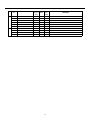
GET Commands
What are GET Commands?
• They are commands for outputting TXD such as adjustment data from the internal microcomputer of the plasma
display to a PC.
• Adjustment data, etc., is output in ASCII code.
NOTE: Command names are given inside brackets < >.
• Data output format
STX (o2hex)
Data
Data
....
Checksum
ETX (03hex)
NOTE:
1) GET commands will be invalid when no ID NO. Set is assigned to the set.
2) GET commands will be invalid when wildcard (*) is used in the ID No. Set when sending the command.
1) <GST> (GET STATUS)
Order
Data Contents
Size
Remarks
1
Display data
3byte
See below
2
Power data
3byte
See below (The third character is sub input)
3
Input function data (main)
3byte
4
Input function data (sub)
3byte
Input data when GST is received (INPUT1 to 5 is displayed as IN1 to 5)
Sub input data when GST is received Note 3
5
Screen size data
1byte
See below
6
2-screen display
1byte
0: OFF (1 screen)
3: PinP (upper right)
6: PoutP
7
FUNCTIONAL LOCK data
1byte
0: LOCK OFF
1: BUTTONS LOCK
2: IR LOCK
3: IR & BUTTONS LOCK
4: MEMORY LOCK
8
Dummy Data
3byte
(3-digit number)
9
Temperature data 2
3byte
10
Temperature data 3
3byte
(Internal temperature: Reference value) oC Note 1
(Internal temperature: Reference value) oC Note 1
11
Serial
15byte
12
Dummy data
3byte
13
Dummy data
3byte
14
HOURMETER
5byte
15
Checksum
2byte
Display data
Power Data
Screen size data
(INPUT1 to 5 is displayed as IN1 to 5)
1: 2-SCREEN
4: PinP (upper left)
2: PinP (lower right)
5: PinP (lower left)
(3-digit number)
Display the time.
First character
Generation data: 4 (fixed)
Second character
Inch data: 4 (43 inches), 5 (50 inch)
Third character
Destination data: M (fixed)
First character
Power state & signal state
Second character
PN (POWER ON & normal signal input)
PL (POWER ON & no input)
PO (POWER ON & OUT OF RANGE signal input)
SN (Normal standby)
SW (Standby by AUTO POWER OFF)
SS (Standby by SD or PD)
Third character
Sub input signal state during multi-screen display
N (Normal signal input) L (No input)
O (OUT OF RANGE signal input)
First character
(0) Pix by Pix or Letterbox, (1) STD (4:3), (2) ANAMPHC 16:9, (3) Letterbox
(1080i), (4) Cinema, (5) Virtualwide, (8) Letterbox (1035i), (9) Underscan
NOTE 1) During standby and immediately after POWER ON, the proper value is not output. In this case, wait a moment after POWER ON, then
get the data. The temperature data is output as a reference (the values are not guaranteed values). Normally, refer to temperature data 3.
NOTE 2) During standby and during 1-screen display, dummy data (symbol) is output.
NOTE 3) During standby and during 1-screen display the values stored in memory for the product are output.
28
2) <GPI> (GET PICTURE DATA: Gets installer/Picture data.)
Order
Data Contents
Size
Remarks
1
CONTRAST
3byte
#
2
BRIGHTNESS
3byte
#
3
C. DETAIL R (RED)
3byte
#
4
C. DETAIL Y (YELLOW)
3byte
#
5
C. DETAIL G (GREEN)
3byte
#
6
C. DETAIL C (CYAN)
3byte
#
7
C. DETAIL B (BLUE)
3byte
#
8
C. DETAIL M (MAGENTA)
3byte
#
9
H SHARPEN
3byte
Outputs dummy data for video signal. #
10
V SHARPEN
3byte
Outputs dummy data for video signal. #
11
COLOR
3byte
Outputs dummy data for PC signal. #
12
TINT
3byte
Outputs dummy data for PC signal. #
13
SHARPNESS
3byte
Outputs dummy data for PC signal. #
14
Input function data (main)
3byte
15
Screen size data
1byte
16
Check sum
2byte
• 7 and 8 output the same contents as GST items 3 and 5.
• When the type of # signal is not set, dummy data is output.
3) <GWB> (GET WHITE BAL. DATA: Gets installer/WHITE BAL. data.)
Order
Data
Size
Remarks
1
R. GAIN
3byte
#
2
G. GAIN
3byte
#
3
B. GAIN
3byte
#
4
R. OFFSET
3byte
#
5
G. OFFSET
3byte
#
6
B. OFFSET
3byte
#
7
Input function data (main)
3byte
8
Screen size data
1byte
9
Check sum
2byte
• 7 and 8 output the same contents as GST items 3 and 5.
• When the type of # signal is not set, dummy data is output.
4) <GPS> (GET POSITION DATA: Gets installer/SCREEN data.)
Order
Data
Size
Remarks
1
H SHIFT
3byte
#
2
V SHIFT
3byte
#
3
H. SIZE
3byte
#
4
V. SIZE
3byte
#
5
FREQ. ADJ.
3byte
Outputs dummy data for PC digital and Video signal. #
6
PHASE ADJ.
3byte
Outputs dummy data for PC digital and Video signal. #
7
Input function data (main)
3byte
8
Screen size data
1byte
9
Check sum
2byte
• 7 and 8 output the same contents as GST items 3 and 5.
• When the type of # signal is not set, dummy data is output.
29
5) <GSS> (GET STATUS SETUP: Gets menu and installer SETUP data.)
Order
Data
Size
Output
Remarks
1
GAMMA
1byte
1: GAMMA 2.0
3: GAMMA 2.2
5: DRE HIGH
7: HIGH CNT.
2
BRT. ENHANCE
1byte
0:OFF
3
SUB VOLUME
2byte
00 to 20
4
COLOR TEMP.
1byte
1: LOW
3: MIDDLE
5: HIGH
2: MID LOW
4: MID HIGH
#
5
VIDEO NR
1byte
0: OFF
3: MIDDLE
2: LOW
4: HIGH
#
6
MPEG NR
1byte
0: OFF
3: MIDDLE
2: LOW
4: HIGH
#
7
CTI
1byte
0: OFF
8
CINEMAMODE
1byte
0: OFF 1: STANDARD
2: ADVANCE
#
9
COLOR DECODING
1byte
1: RGB 1: COMPONENT1
2: COMPONENT2
#
10
COLOR SYSTEM
1byte
1: AUTO
4: SECAM
6: PAL M
#
11
SIGNAL FORMAT
3byte
12
Dummy data
3byte
13
Input function data (main)
3byte
14
Screen size data
1byte
15
Check sum
2byte
SIGNAL FORMAT
2: GAMMA 1.8
4: DRE MID
6: DRE LOW
1: ON
1: ON
2: NTSC
3: PAL
5: 4.43NTSC
7: PAL N
#
#
# (color transient improvement)
# See below
S01 .................... VGA or XGA or SXGA or 720-PC
(720-PC can be selected only when a video card is mounted.)
S02 .................... WVGA or WXGA or SXGA+
S03 .................... 535p or 750p (Either one can be selected only when a video
card is mounted.) or PC AUTO
*** .................... Dummy data is output for signals other than those above.
• 13 and 14 output the same contents as GST items 3 and 5.
• Dummy data is output for setting data that cannot be output depending on the type of # signal.
30
6) <GSO> (GET STATUS OPTION: Gets menu and installer OPTION data.)
Order
Data
Size
1
ENERGY MODE
1byte
1: STANDARD
3: MODE 2
5: AUTO
2
ORBITER
1byte
0:OFF
1: ON
3
MASK CONTROL
1byte
0:OFF
1: ON
4
AUDIO OUT
1byte
1:FIXED 2: VARIABLE
5
SCREEN MASK
1byte
0: OFF
2: INVERSE
4: RED
6: BLUE
6
SIDEBAR ADJ.
1byte
1: NORMAL 2: OVERLAY1
3: OVERLAY2
7
R. SIDEBAR ADJ. LEVEL
3byte
000 to 255
8
G. SIDEBAR ADJ. LEVEL
3byte
000 to 255
9
B. SIDEBAR ADJ. LEVEL
3byte
000 to 255
10
2x2
1byte
0:OFF
11
2 x 2 LAYOUT & TYPE
1byte
1: NORMAL &UP LEFT
2: NORMAL &DOWN LEFT
3: NORMAL &UP RIGHT
4: NORMAL &DOWN RIGHT
5: ADJUSTED &UP LEFT
6: ADJUSTED &DOWN LEFT
7: ADJUSTED &UP RIGHT
8: ADJUSTED & DOWN RIGHT
12
MIRROR MODE
1byte
0:OFF
1: X
13
OSD
1byte
0:OFF
1: ON
14
FRONT INDICATOR
1byte
0:OFF
1: ON
15
FAN CONTROL
1byte
1: AUTO
16
COLOR MODE
1byte
1: NORMAL 2: ISF
17
RUNCO PRO UNDERSCAN
1byte
0:OFF
18
RUNCO PRO COLOR OFF
1byte
0:DISABLE 1: ENABLE
19
FRC
1byte
1: MODE1 2: MODE2
3: MODE3
20
Dummy data
3byte
21
Input function data (main)
3byte
22
Sceen size data
1byte
23
Check sum
2byte
Total
Output
Remarks
2: MODE 1
4: MODE 3
3: WHITE
5: GREEN
7: YELLOW
1: ON
2: Y
3:XY
2: MAX
1: ON
34 Byte
• 21and 22 output the same contents as GST items 3 and 5.
31
DIMENSIONS
CW-43MC Plasma
�
�����
�����
������
������
������
������
���������
������
������
�����
������
������
�
32
������
������
�����
������
�����
�
������
CW-50MC Plasma
�
�����
�����
������
������
������
������
������
���������
������
������
������
�����
33
������
�����
�����
������
�
������
������
�
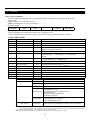
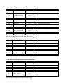
SPECIFICATIONS
Plasma
CW-43MC
Native Resolution:
Screen Size:
Screen Aspect Ratio:
Available Aspect Ratios:
1024 x 768
43 in. (diagonal)
16:9
4:3, Letterbox,
16:9 Anamorphic, VirtualWide
Image Area (W x H):
37 3/8 in. (949.30 mm) x
21 1/8 in. (536.60 mm)
DTV Compatibility:
480p, 720p, 1080i
Contrast Ratio:
1000:1
Data/Graphics Capability: 640 x 400 to 1600 x 1200
Inputs:
(1) Composite, (1) S-Video
(1) RCA Component Video
(1) RGB 15 pin, (1) DVI w/HDCP,
(1) RS-232C, (1) I/R
(5) Stereo Audio - single mini jack
Power Requirements:
100 -120 VAC, 50/60 Hz
220V AC (Preset at the factory only)
Power Consumption:
380W
Operating Environments: 32˚ - 104˚F (0˚ - 40˚C), 20-80%
Humidity (non-condensing)
Dimensions
Width: 43 3/8 in. (1102 mm)
Depth: 4 in. (101.60 mm)
Height: 26 3/4 in. (679.40 mm)
Weight: 80 lbs. (36.3 kg)
Regulatory Approvals:
FCC
Limited Warranty:
(3) Three years parts and labor (not
including the plasma glass panel) from
the date of delivery to the end user.
(1) One year parts and labor on the
plasma glass panel from the date of
delivery to the end user.
34
CW-50MC
1280 x 768
50 in. (diagonal)
16:9
4:3, Letterbox,
16:9 Anamorphic, VirtualWide
43 1/4 in. (1099 mm) x
24 1/2 in. (622.30 mm)
480p, 720p, 1080i
1000:1
640 x 400 to 1600 x 1200
(1) Composite, (1) S-Video
(1) RCA Component Video
(1) RGB 15 pin, (1) DVI w/HDCP,
(1) RS-232C, (1) I/R
(5) Stereo Audio - single mini jack
100 -120 VAC, 50/60 Hz
220V AC (Preset at the factory only)
480W
32˚ - 104˚F (0˚ - 40˚C), 20-80%
Humidity (non-condensing)
Width: 49 1/4 in. (1251 mm)
Depth: 4 3/32 in. (104 mm)
Height: 30 1/8 in. (765.20 mm)
Weight: 96 lbs. (44.0 kg)
FCC
(3) Three years parts and labor (not
including the plasma glass panel) from
the date of delivery to the end user.
(1) One year parts and labor on the
plasma glass panel from the date of
delivery to the end user.
RUMA-011000
11-08-04 v2.1
Runco International • Union City, CA 94587 • Ph: 510-324-7777 • Fax: 510-324-9300 • www.runco.com