1
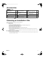
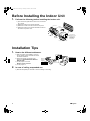
00_CV_3P171284-2C.fm Page 1 Monday, October 27, 2008 4:23 PM
INSTALLATION
MANUAL
R410A Split Series
Installation manual
R410A Split series
Models
FLXS25BVMB
FLXS35BVMB
FLXS50BVMB
FLXS60BVMB
FLX25BVMB
FLX35BVMB
FLXS25BAVMB
FLXS35BAVMB
FLXS50BAVMB
FLXS60BAVMB
FLKS25BVMB
FLKS35BVMB
FLKS50BVMB
FLKS60BVMB
FLK25BVMB
FLK35BVMB
FLKS25BAVMB
FLKS35BAVMB
FLKS50BAVMB
FLKS60BAVMB
English
Installationsanleitung
Split-Baureihe R410A
Deutsch
Manuel d’installation
Série split R410A
Français
Montagehandleiding
R410A Split-systeem
Manual de instalación
Serie Split R410A
Manuale d’installazione
Serie Multiambienti R410A
Εγχειρßδιο εγκατÜστασηò
διαιροýìενηò σειρÜò R410A
Manual de Instalação
Série split R410A
Рóêоводство по монтажó
Серия R410A с раздельной óстановêой
Nederlands
Español
Italiano
ΕλληνικÜ
Portugues
Рóссêий
Low Voltage 2006/95/EC
Electromagnetic Compatibility 2004/108/EC *
Shinri Sada
Manager Quality Control Department
1st. of Nov. 2008
FLKS25BVMB, FLKS35BVMB, FLXS25BVMB, FLXS35BVMB, FLK25BVMB, FLK35BVMB,
FLX25BVMB, FLX35BVMB, FLKS50BVMB, FLKS60BVMB, FLXS50BVMB, FLXS60BVMB,
FLKS25BAVMB, FLKS35BAVMB, FLKS50BAVMB, FLKS60BAVMB,
FLXS25BAVMB, FLXS35BAVMB, FLXS50BAVMB, FLXS60BAVMB
DAIKIN INDUSTRIES, LTD.
Umeda Center Bldg., 2-4-12, Nakazaki-Nishi,
Kita-ku, Osaka, 530-8323 Japan
74736-KRQ/EMC97-4957
KEMA Quality B.V.
DAIKIN.TCF.015 K1/07-2007
3SB64526-4.fm Page 1 Monday, December 1, 2008 3:28 PM
3SB64526-4
01_EN_3P171284-2C.fm Page 1 Monday, October 27, 2008 4:34 PM
Safety Precautions
• Read these Safety Precautions carefully to ensure correct installation.
• This manual classifies the precautions into WARNING and CAUTION.
Be sure to follow all the precautions below: they are all important for ensuring safety.
WARNING...............Failure to follow any of WARNING is likely to result in such grave consequences as death or serious injury.
CAUTION...............Failure to follow any of CAUTION may result in grave consequences in some cases.
• The following safety symbols are used throughout this manual:
Be sure to observe this instruction.
Be sure to establish an earth connection.
Never attempt.
• After completing installation, test the unit to check for installation errors. Give the user adequate instructions concerning the use
and cleaning of the unit according to the Operation Manual.
WARNING
• Installation should be left to the dealer or another professional.
Improper installation may cause water leakage, electrical shock, or fire.
• Install the air conditioner according to the instructions given in this manual.
Incomplete installation may cause water leakage, electrical shock, or fire.
• Be sure to use the supplied or specified installation parts.
Use of other parts may cause the unit to come to lose, water leakage, electrical shock, or fire.
• Install the air conditioner on a solid base that can support the weight of the unit.
An inadequate base or incomplete installation may cause injury in the event the unit falls off the base.
• Electrical work should be carried out in accordance with the installation manual and the national electrical wiring
rules or code of practice.
Insufficient capacity or incomplete electrical work may cause electrical shock or fire.
• Be sure to use a dedicated power circuit. Never use a power supply shared by another appliance.
• For wiring, use a cable length enough to cover the entire distance with no connection.
Do not use an extension cord. Do not put other loads on the power supply, use a dedicated power circuit.
(Failure to do so may cause abnormal heat, electric shock or fire.)
• Use the specified types of wires for electrical connections between the indoor and outdoor units.
Firmly clamp the interconnecting wires so their terminals receive no external stresses. Incomplete connections or clamping may cause terminal overheating or fire.
• After connecting interconnecting and supply wiring be sure to shape the cables so that they do not put undue force
on the electrical covers or panels.
Install covers over the wires. Incomplete cover installation may cause terminal overheating, electrical shock, or fire.
• If any refrigerant has leaked out during the installation work, ventilate the room.
(The refrigerant produces a toxic gas if exposed to flames.)
• After all installation is complete, check to make sure that no refrigerant is leaking out.
(The refrigerant produces a toxic gas if exposed to flames.)
• When installing or relocating the system, be sure to keep the refrigerant circuit free from substances other than the
specified refrigerant (R410A), such as air.
(Any presence of air or other foreign substance in the refrigerant circuit causes an abnormal pressure rise or rupture, resulting in injury.)
• During pump-down, stop the compressor before removing the refrigerant piping.
If the compressor is still running and the stop valve is open during pump-down, air will be sucked in when the refrigerant piping is removed,
causing abnormal pressure in the freezer cycle which will lead to breakage and even injury.
• During installation, attach the refrigerant piping securely before running the compressor.
If the compressor is not attached and the stop valve is open during pump-down, air will be sucked in when the compressor is run, causing
abnormal pressure in the freezer cycle which will lead to breakage and even injury.
• Be sure to establish an earth. Do not earth the unit to a utility pipe, arrester, or telephone earth.
Incomplete earth may cause electrical shock, or fire. A high surge current from lightning or other sources may cause damage to the
air conditioner.
• Be sure to install an earth leakage breaker.
Failure to install an earth leakage breaker may result in electric shocks, or fire.
CAUTION
• Do not install the air conditioner in a place where there is danger of exposure to inflammable gas leakage.
If the gas leaks and builds up around the unit, it may catch fire.
• Establish drain piping according to the instructions of this manual.
Inadequate piping may cause flooding.
• Tighten the flare nut according to the specified method such as with a torque wrench.
If the flare nut is tightened too hard, the flare nut may crack after a long time and cause refrigerant leakage.
1
■English
01_EN_3P171284-2C.fm Page 2 Monday, October 27, 2008 4:34 PM
Accessories
Indoor unit
A – Q
A Mounting plate
1
G AAA dry-cell batteries
2
N Heat insulation tube
(Extension auxiliary pipe)
1
B Photocatalytic deodorizing filter
1
J Side covers
2
P Heat insulation tube
(Refrigerant pipe)
1
C Air purifying filter
1
K Operation manual
1
Q Binding bands
4
D Wireless remote controller
1
L Installation manual
1
E Remote controller holder
1
M Extension auxiliary pipe
2
• The extension auxiliary pipe M
N is not included for FLX(S)25, FLX(S)35, FLK(S)25 and FLK(S)35.
Choosing an Installation Site
• Before choosing the installation site, obtain user approval.
1.
Indoor unit.
• The indoor unit should be sited in a place where:
1) the restrictions on installation specified in the indoor unit installation drawings are met,
2) both air intake and exhaust have clear paths met,
3) the unit is not in the path of direct sunlight,
4) the unit is away from the source of heat or steam,
5) there is no source of machine oil vapour (this may shorten indoor unit life),
6) cool air is circulated throughout the room,
7) the unit is away from electronic ignition type fluorescent lamps (inverter or rapid start type) as they may shorten the
remote control range,
8) the unit is at least 1 metre away from any television or radio set (unit may cause interference with the picture or sound).
2.
Wireless remote controller.
1) Turn on all the fluorescent lamps in the room, if any, and find the site where remote control signals are properly received
by the indoor unit (within 7 metres).
■English
2
01_EN_3P171284-2C.fm Page 3 Monday, October 27, 2008 4:34 PM
Before Installing the Indoor Unit
1.
Perform the following before installing the indoor unit.
1) Open the air inlet grille and the screw cover, and remove
the 7 screws.
2) Release the claws in the 3 places indicated.
3) Release the center hook and remove the front panel.
4) Release the claws in the 2 places indicated and remove
the electric component cover.
Screw cover
2 Claw
Electric
component cover
4
3
Claw
Drain pan hook
Front panel
1
Drain pan
hook
2
Air inlet grille
Front panel
Front panel hook
* Move the front panel
in the direction of
the arrow
to
remove it from the
drain pan hook.
To release the center hook
Installation Tips
How to the different addresses.
CEILING
2.
FLOOR
1) When two indoor units installed in one room,
the two wireless remote controllers can be set
for different addresses.
2) Remove the electric component cover.
(Refer to the BEFORE INSTALLING THE
INDOOR UNIT.)
3) Cut the jumper JA on PCB.
Wireless remote controller
4) Cut the jumper J4.
SW2
1.
Wireless
remote
controller
J4
ADDRESS JA
EXIST
1
CUT
2
J4
ADDRESS
EXIST
1
CUT
2
In case of ceiling suspended use.
1) Slide the switch(SW2) to “CEILING” in case of installing on the ceiling.
3
■English
01_EN_3P171284-2C.fm Page 4 Monday, October 27, 2008 4:34 PM
Indoor Unit Installation Drawings
There should be no space
between ceiling and the unit.
Space for installation work
Min. (200mm)
Space for installation work
Min. (200mm)
50mm or more
from walls
Air filters
A Mounting plate
The mounting plate
should be installed
on a wall which can
support the weight
of the indoor unit.
Screws
(Field supply:
M4 × 25L)
B Photocatalytic
deodorizing filter
C Air purifying filter
Cut thermal insulation pipe to an
appropriate length and wrap it with tape,
making sure that no gap is left in the
insulation pipe’s cut line.
B Photocatalytic
deodorizing filter or
C Air purifying filter
Space for
installation
work Min.
(200mm)
Hold the recessed
parts of the frame
and unhook the four
claws.
D Wireless
remote
controller
Screws
(Field supply:
M3 × 20L)
■English
Wrap the insulation
pipe with the
finishing tape from
bottom to top.
ON
OFF
Caulk
pipe hole
gap with
putty.
50mm or more
from floor
Space for
installation
work Min.
(200mm)
Before screwing the remote
controller holder to the wall, make
sure that control signals are
properly received by indoor unit.
E
Remote
controller
holder
4
01_EN_3P171284-2C.fm Page 5 Monday, October 27, 2008 4:34 PM
Indoor Unit Installation Drawings
Ceiling mounting.
Local drain pipe
Rear side pipinghole ø65mm
Ceiling
55
*1 more than 170
1.
40
Ceiling
Wall
50
*1 Determine the position of the
feed-through hole so that the
local piping is placed in a
downward sloping direction.
Rear side drainhose hole ø40mm
1,050
40
138
40-45
Drain hose
490
Right side piping
hole ø65mm
22
35
40
230
980
Wall
55
Top side piping hole ø65mm
2.
Wall mounting.
Under side piping
hole ø80mm
55
Wall
Right side
piping hole
ø80mm
40
40
Wall
1,050
Floor
35
800
40
97
30
255
Drain pipe
162
48
Gas pipe
490
Liquid pipe
Wall
102 26
Floor
150
Connection position
5
Floor
Rear side piping hole
ø80mm
55
■English
01_EN_3P171284-2C.fm Page 6 Monday, October 27, 2008 4:34 PM
Indoor Unit Installation
Ceiling Mounting
1.
Installing the suspension bolt.
1) Install the suspension bolt so that it can support the indoor unit; adjust distance to ceiling before installation.
2) Mount the indoor unit according to the installation drawings and tighten it securely with M10 nut. (4 places)
3) After mounting the indoor unit on the ceiling, install each part as shown in the diagram on the right.
J Side cover
25-30
40-45
Ceiling
Suspension
bolt
Spring
washer
Nut (M10)
Washer
Spring
washer
Nut (M10)
Suspension bolt
(M10)
M10 nut
Washer
Electric component cover
(2 claws)
J Side cover
(6 claws)
Front grille
• Incline condition for installation
less than 1
less than 1
2.
Installing indoor unit.
1) Connect the extension auxiliary pipe ( M , supplied) to the local piping. (See 1 on
the next page)
(Applies to both ceiling mounting and wall mounting units.)
2) Prepare the local piping at the connection point for the drain pipe, as shown in the
installation drawings.
Note:Be sure to place the drain hose as shown in the diagram on the right, in a
downward sloping direction.
3) Connect the drain hose to the local drain pipe.
Position the interconnecting wire in the same direction as the piping.
Upper right-side piping
Right-side
piping
Cut away
here for rightside piping
Drain hose
Right-back piping
Bottom frame cover
Cut away
here for rightback piping
Note:
For upper right-side
piping, remove the bottom
frame cover before
installing the indoor unit.
• Feed-through portion of drain hose
For determining the position of the drain hose, perform the following procedures.
Bottom frame
Bottom
frame
claw
Panel
1 Cut out with
a nipper.
■English
2 Cut out the
drain hose
portion.
3 Screw it to the
bottom frame.
Drain hose
4 After determining the position of the
drain hose, hook the panel to the
bottom frame claws.
6
01_EN_3P171284-2C.fm Page 7 Monday, October 27, 2008 4:34 PM
Indoor Unit Installation
Wall Mounting
3.
Installation.
• Install the indoor unit on the wall according to the installation drawings.
1) Hang the indoor unit on the hooks of A mounting plate. (2 places)
2) Fix the three holes in the lower portion of the indoor unit with M4 × 25L screws.
A Mounting plate
J Side cover
(6 claws)
J Side cover
M4 × 25L
Indoor unit
hook portion
Electric component cover
(2 claws)
Front grille
A Mounting plate
Condition for installation
less than 1
• Work should be performed to match the direction of the piping, as the extension auxiliary pipe ( M , supplied) and installation methods vary depending on the direction the piping is brought out.
1) Select the extension auxiliary pipe in accordance with the
direction of the piping. (This should be done without the
3)
included piping for wall-mounted right-back piping and
Bottomceiling-mounted upper right-side piping.)
right piping
2) Attach the heat insulation tube N to the extension auxiliary pipe. (Make sure there are no gaps.)
3) Attach the extension auxiliary pipe to the product.
2)
Right side
piping
7
■English
01_EN_3P171284-2C.fm Page 8 Monday, October 27, 2008 4:34 PM
4.
Installing indoor unit.
1) Connect the extension auxiliary pipe ( M , supplied) to the local piping.
(Applies to both ceiling mounting and wall mounting units.)
2) Prepare the local piping at the connection point for the drain pipe, as
shown in the installation drawings.
3) Connect the drain hose to the local drain pipe.
Position the interconnecting wire in the same direction as the piping.
Note:
Remove the bottom frame cover for right-back piping
before installing the indoor unit.
Right-side piping
Cut away here for
right-side piping
Cut away here
for bottom-right
piping
Right-back piping
Bottom-right piping
Commonality Between Ceiling Mounting and Wall Mounting
With a Multi indoor unit , install as described in the installation manual supplied with the Multi outdoor unit.
5.
Wiring.
1) Strip wire ends (15mm).
2) Match wire colours with terminal numbers on indoor and outdoor unit’s terminal blocks and firmly screw wires to the corresponding terminals.
3) Connect the earth wires to the corresponding terminals.
4) Pull wires to make sure that they are securely latched up, then retain wires with wire retainer.
5) In case of connecting to an adapter system. Run the remote control cable and attach the S21 connector as the illustration
on the right.
6) Shape the wires so that the service lid fits securely, then close service lid.
Remote control cable (option)
Terminal blocks
Secure the wires so that
the structure does not rise.
S21 Fix securely so that
external force is not directly
applied to the terminals.
Earth wire
Electric component box
Wire clamp
Use designated wire
to connect it securely.
Firmly fix the wires with
the terminal screws.
Outdoor unit
When wire length exceeds
10m, use 2.0mm wires.
Indoor
unit
1 23
LN
1
2
3
Firmly fix the wires with
the terminal screws.
H05VV
Warning
1) Do not use tapped wires, stand wires, extensioncords, or starburst connections, as they may cause overheating, electrical
shock, or fire.
2) Do not use locally purchased electrical parts inside the product. (Do not branch the power for the drain pump, etc., from the
terminal block.) Doing so may cause electric shock or fire.
■English
8
01_EN_3P171284-2C.fm Page 9 Monday, October 27, 2008 4:34 PM
Indoor Unit Installation
6.
Insulation of refrigerant pipes.
After checking for refrigerant leaks
• Joints in liquid pipe and the gas pipe must be insulated with P heat insulation tube attached with Q binding bands.
• Cut P heat insulation tube to appropriate length.
Q Binding band
P Heat insulation tube
7.
Drain piping.
1) Connect the drain hose, as described below.
Drain hose must
slope downward.
Allow no trap to
form in the piping.
Do not allow
end of hose to
touch water.
Ceiling mounting
Wall mounting
2) Pour water into the drain pan from the right side to check that water flows smoothly from the drain hose.
Ceiling mounting
Wall mounting
3) When drain hose requires extension, obtain an extension hose commercially
available.
After connecting the local drain hose, tape the slits of the heat insulation tube.
Be sure to attach this
part cut from the
panel.
Indoor unit
drain hose
Tape here
(Field supply)
Remove this socket for
Wall mounting.
9
Extension
drain hose
(Field supply)
Heat insulation
tube (More than
10mm: Field
supply)
■English
01_EN_3P171284-2C.fm Page 10 Monday, October 27, 2008 4:34 PM
Refrigerant Piping Work
With a Multi indoor unit , install as described in the installation manual supplied with the Multi outdoor unit.
1.
Flaring the pipe end.
(Cut exactly at
right angles.)
1) Cut the pipe end with a pipe cutter.
2) Remove burrs with the cut surface facing downward so that the chips do not enter the pipe.
3) Put the flare nut on the pipe.
4) Flare the pipe.
5) Check that the flaring is properly made.
Remove burrs
Flaring
Set exactly at the position shown below.
A
Die
A
Flare tool for R410A
Conventional flare tool
Clutch-type
Clutch-type (Rigid-type) Wing-nut type (Imperial-type)
0-0.5mm
1.0-1.5mm
1.5-2.0mm
Check
Flare’s inner
surface must
be flaw-free.
The pipe end must
be evenly flared in
a perfect circle.
Make sure that the
flare nut is fitted.
Warning
1)
2)
3)
4)
5)
6)
2.
Do not use mineral oil on flared part.
Prevent mineral oil from getting into the system as this would reduce the lifetime of the units.
Never use piping which has been used for previous installations. Only use parts which are delivered with the unit.
Do never install a drier to this R410A unit in order to guarantee its lifetime.
The drying material may dissolve and damage the system.
Incomplete flaring may cause refrigerant gas leakage.
Refrigerant piping.
Caution
1) Use the flare nut fixed to the main unit. (To prevent cracking of the flare nut by aged deterioration.)
2) To prevent gas leakage, apply refrigeration oil only to the inner surface of the flare. (Use refrigeration oil for R410A.)
3) Use torque wrenches when tightening the flare nuts to prevent damage to the flare nuts and gas leakage.
Align the centres of both flares and tighten the flare nuts 3 or 4 turns by hand. Then tighten them fully with the torque
wrenches.
[Apply oil]
[Tighten]
Apply refrigeration oil to
the inner surface of the
flare.
Do not apply refrigeration
oil to the outer surface.
Torque wrench
Flare nut
Spanner
Piping union
Flare nut
Do not apply refrigeration
oil to the flare nut avoid
tightening with over torque.
Flare nut tightening torque
Gas side
3/8 inch
Liquid side
1/2 inch
l
1/4 inch
l
32.7-39.9N m
49.5-60.3N m
14.2-17.2N l m
(333-407kgf l cm)
(505-615kgf l cm)
(144-175kgf l cm)
2-1. Caution on Piping Handling
1) Protect the open end of the pipe against dust and moisture.
2) All pipe bends should be as gentle as possible. Use a pipe bender
for bending.
■English
Be sure to
place a cap.
Rain
Wall
If no flare cap is
available, cover
the flare mouth
with tape to keep
dirt or water out.
10
01_EN_3P171284-2C.fm Page 11 Monday, October 27, 2008 4:34 PM
Refrigerant Piping Work
2-2. Selection of Copper and Heat Insulation materials
• When using commercial copper pipes and fittings, observe the following:
1) Insulation material: Polyethylene foam
Heat transfer rate: 0.041 to 0.052W/mK (0.035 to 0.045kcal/mh°C)
Refrigerant gas pipe’s surface temperature reaches 110°C max.
Choose heat insulation materials that will withstand this temperature.
2) Be sure to insulate both the gas and liquid piping and to provide insulation dimensions as below.
Gas side
20/25/35 class
50/60 class
Inter-unit wiring
Gas pipe
Liquid pipe
Gas pipe
insulation
Liquid pipe
insulation
Finishing tape
Drain hose
Gas pipe thermal insulation
Liquid side
O.D. 9.5mm
O.D. 12.7mm
O.D. 6.4mm
Minimum bend radius
30mm or more 40mm or more 30mm or more
Thickness 0.8mm (C1220T-O)
Liquid pipe
thermal
20/25/35 class 50/60 class
insulation
I.D. 12-15mm I.D. 14-16mm I.D. 8-10mm
Thickness 10mm Min.
3) Use separate thermal insulation pipes for gas and liquid refrigerant pipes.
11
■English
01_EN_3P171284-2C.fm Page 12 Monday, October 27, 2008 4:34 PM
Trial Operation and Testing
1.
Trial operation and testing.
1-1 Measure the supply voltage and make sure that it falls in the specified range.
1-2 Trial operation should be carried out in either cooling or heating mode.
■ For Heat pump
• In cooling mode, select the lowest programmable temperature; in heating mode, select the highest programmable temperature.
1) Trial operation may be disabled in either mode depending on the room temperature.
Use the remote control for trial operation as described below.
2) After trial operation is complete, set the temperature to a normal level (26°C to 28°C in cooling mode, 20°C to 24°C in
heating mode).
3) For protection, the system disables restart operation for 3 minutes after it is turned off.
■ For Cooling only
• Select the lowest programmable temperature.
1) Trial operation in cooling mode may be disabled depending on the room temperature.
Use the remote control for trial operation as described below.
2) After trial operation is complete, set the temperature to a normal level (26°C to 28°C).
3) For protection, the unit disables restart operation for 3 minutes after it is turned off.
1-3 Carry out the test operation in accordance with the Operation Manual to ensure that all functions and parts,
such as louver movement, are working properly.
• The air conditioner requires a small amount of power in its standby mode. If the system is not to be used for some
time after installation, shut off the circuit breaker to eliminate unnecessary power consumption.
• If the circuit breaker trips to shut off the power to the air conditioner, the system will restore the original operation
mode when the circuit breaker is opened again.
Trial Operation from Remote Controller
1) Press ON/OFF button to turn on the system.
2) Simultaneously press centor of TEMP button and MODE button.
3) Press MODE button twice.
(“ ” will appear on the display to indicate that Trial Operation mode is selected.)
4) Trial run mode terminates in approx. 30 minutes and switches into normal mode. To quit a trial operation, press ON/OFF
button.
2.
Test items.
Test Items
Indoor and outdoor units are installed properly on solid bases.
Symptom
(diagnostic display on RC)
Fall, vibration, noise
No refrigerant gas leaks.
Incomplete cooling/heating function
Refrigerant gas and liquid pipes and indoor drain hose extension are thermally insulated.
Water leakage
Draining line is properly installed.
Water leakage
System is properly earthed.
Electrical leakage
The specified wires are used for interconnecting wire connections.
Inoperative or burn damage
Indoor or outdoor unit’s air intake or exhaust has clear path of air.
Stop valves are opened.
Incomplete cooling/heating function
Indoor unit properly receives remote control commands.
Inoperative
■English
Check
12
00_CV_3P171284-2C.fm Page 2 Monday, October 27, 2008 4:23 PM
Two-dimensional bar code is a code
for manufacturing.
3P171284-2C M02B074H
(0812) HT