1
ELAN
HOME
SYSTEMS
S128P INSTALLATION MANUAL
Preface
Purpose of This Manual
This manual provides step-by-step installation instructions and connection examples, along with basic user information for installation and ongoing use of the S128P Multi-Room Controller. This manual is written for the installer
of this equipment.
Organization
The following information is contained in this manual:
Safety Information
Provides a comprehensive list of safety practices and procedures allowing for
the safe installation and operation of ELAN Home Systems’ S128P Multi-Room A/V
Controller.
S128P Introduction
Provides an introduction to ELAN Home Systems’ S128P MultiRoom A/V Controller, along with system features to include Front and
Rear panel controls, indicators and connections, along with a short description
of each.
S128P System Design
Overview
Provides a system design application overview of the S128P
Multi-Room A/V Controller for use in audio, video and automation applications.
S128P Connections
Provides a description of S128P Multi-Room A/V Controller system connections to
connections made with an ELAN System Precision Panel (SPP) and direct connections
from the S128P to all other components.
Troubleshooting
Provides troubleshooting tables to help fix common discrepancies that may
be associated with the S128P Multi-Room A/V Controller.
Specifications
Appendix A provides equipment specifications for the S128P
Multi-Room A/V Controller.
Programming
Appendix B provides a basic overview of steps necessary to download programming information from VIA!®TOOLS or ELAN®TOOLS Setup software to the S128P
RS-232 Protocol
Appendix C contains all information necessary to create RS-232 command
structures when controlling the S128P with a third-party RS-232 control device.
Rack Mounting
Appendix D provides specifications for rack mounting the S128P
Multi-Room A/V Controller.
© ELAN Home Systems 2009 • All rights reserved.
Page 1
S128P
ELAN
INSTALLATION MANUAL
HOME
SYSTEMS
Safety Information
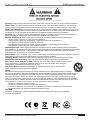
WARNING
RISK OF ELECTRIC SHOCK
DO NOT OPEN!
CAUTION: TO REDUCE THE RISK OF ELECTRIC SHOCK, DO NOT
REMOVE COVER (OR BACK). NO USER SERVICEABLE PARTS INSIDE.
REFER SERVICING TO QUALIFIED SERVICE PERSONNEL.
CAUTION: RISK OF EXPLOSION IF BATTERY IS REPLACED BY AN
INCORRECT TYPE. DISPOSE OF USED BATTERIES ACCORDING TO
THE INSTRUCTIONS.
The lightning flash with arrowhead symbol within an equilateral triangle is intended to
alert the user to the presence of uninsulated "dangerous voltage" within the product's
enclosure that may be of sufficient magnitude to constitute a risk of electric shock to persons.
The exclamation point within an equilateral triangle is intended to alert the user to the presence
of important operating and maintenance (servicing) instruction in the literature accompanying
the appliance.
WARNING: TO REDUCE THE RISK OF FIRE OR SHOCK,
DO NOT EXPOSE THIS APPLIANCE TO RAIN OR MOISTURE.
CAUTION
IMPORTANT SAFETY INFORMATION
Read Information—All the safety and operating information should be read before the appliance is operated.
Follow Information—All operating and use information should be followed.
Retain Information—The safety and operating information should be retained for future reference.
Heed Warnings—All warnings on the appliance and in the operating instructions should be heeded.
Wall Mounting—Mounting of this appliance should be done only by an authorized installer.
Ventilation—The appliances should be situated so that their location or position does not interfere with their proper
ventilation. These appliances should never be placed near or over a radiator or heat register.
-These appliances should not be placed in a built-in installation such as a bookcase or cabinet that may impede the flow of air
through the ventilation openings.
Non-Use Periods—Appliances that are left unattended and unused for long periods of time should be de-energized.
Grounding or Polarization—Do not defeat the safety purpose of the polarized or grounding-type plug. A polarized
plug has two blades with one blade wider than the other blade. A grounding type plug has two blades and a third
grounding prong. The polarized wide blade and the third prong are provided for your safety. If the provided plug does
not fit your outlet, consult an electrician for replacement of the obsolete outlet.
Power Cord Protection—Protect the power cord from being walked on or pinched particularly at plugs, convenience
receptacles and the point where they exit from the apparatus.
Water—Do not use the apparatus near water.
Page 2
© ELAN Home Systems 2009 • All rights reserved.
ELAN
HOME
SYSTEMS
S128P INSTALLATION MANUAL
Cleaning—Unplug the apparatus from the power outlet before cleaning. Use only a dry cloth to clean the apparatus.
Power Lines—An outdoor antenna should be located away from power lines. When installing an outside antenna
system, extreme care should be taken to avoid touching power lines or circuits, as contact with them may be fatal.
Object and Liquid Entry—Never insert objects of any kind through the openings of these appliances, as they may
touch dangerous voltage points or short-out parts that could result in a fire or electric shock. Care should be taken so
that objects do not fall and liquids are not spilled into the appliance through openings in the enclosure.
Servicing—Do not attempt to service these appliances yourself, as opening or removing covers may expose you to
dangerous voltage or other hazards. Refer all servicing to qualified service personnel.
Damage Requiring Service—These appliances should be serviced by qualified service personnel when:
• A power supply connection or a plug has been damaged or
• If liquid has been spilled into the appliance or objects have fallen into the appliance or
• The appliance has been exposed to water or moisture or
• The appliance does not appear to operate normally or exhibits a marked change in performance or
• The appliance has been dropped or the enclosure damaged.
Replacement Parts—When replacement parts are required, be sure the service technician has used replacement
parts specified by the manufacturer or that have the same characteristics as the original part. Unauthorized substitutions
may result in fire, electric shock, or other hazards. The Master Control Unit battery should be replaced only after
turning the power off and only by an authorized installer.
Safety Check—Upon completion of any service or repairs to this audio product, ask the service technician to perform
safety checks to determine that the audio product is in proper operating condition.
Lightning Storms—Unplug this apparatus during lightning storms or when unused for long periods of time.
Attachments and Accessories—Use only attachments/accessories specified by the manufacturer.
Cart, Stand, Tripod, Bracket or Table—Use only with a cart, stand, tripod, bracket or table specified
by the manufacturer, or sold with the apparatus. When a cart is used, use caution when moving the
cart/apparatus combination to avoid injury from tip over.
Disconnect Device—Where the mains plug or an appliance coupler is used as the disconnect
device, the disconnect device shall remain operable.
NOTE:
This equipment has been tested and found to comply with the limits for a Class B digital device, pursuant to
part 15 of the FCC Rules. These limits are designed to provide reasonable protection against harmful interference in a
residential installation. This equipment generates, uses and can radiate radio frequency energy and, if not in-stalled
and used in accordance with the instructions, may cause harmful interference to radio communications. However,
there is no guarantee that interference will not occur in a particular installation. If this equipment does cause harmful
interference to radio or television reception, which can be determined by turning the equipment off and on, the user is
encouraged to try to correct the interference by one or more of the following measures:
• Reorient or relocate the receiving antenna.
• Increase the separation between the equipment and receiver.
• Connect the equipment into an outlet on a circuit different from that to which the receiver is connected.
• Consult the dealer or an experienced radio/TV technician for help.
CAUTION:
Changes or modifications not expressly approved by Elan Home Systems could void the user’s authority
to operate the equipment
© ELAN Home Systems 2009 • All rights reserved.
Page 3
S128P
Page 4
INSTALLATION MANUAL
ELAN
HOME
SYSTEMS
© ELAN Home Systems 2009 • All rights reserved.
ELAN
HOME
SYSTEMS
S128P INSTALLATION MANUAL
Purpose of This Manual ...................................................................................................................... 1
Organization .......................................................................................................................................... 1
Safety Information ............................................................................................................................... 2
Chapter 1: Introduction
The ELAN Story .................................................................................................................................... 9
S128P Features .................................................................................................................................. 10
System S128P Functions & Indicators .......................................................................................... 12
Front Panel ........................................................................................................................................ 12
S128P Front Panel Table ..................................................................................................................... 13
Rear Panel ......................................................................................................................................... 14
S128P Rear Panel Table ..................................................................................................................... 14
Chapter 2: S128P System Design Overview
Introduction ......................................................................................................................................... 16
Pre-Wire ............................................................................................................................................ 16
Applications ........................................................................................................................................ 18
Zone/Sub-Zone Definitions ................................................................................................................ 18
Stereo Zones .................................................................................................................................... 19
Stereo Zone w/ Fixed Sub-Zone .......................................................................................................... 20
Stereo Zone w/ Fixed/Variable Sub-Zone .............................................................................................. 21
Stereo Zone w/ Mono Sub-Zone .......................................................................................................... 23
Chapter 3:S128P Connections
SPP System Precision Panel ........................................................................................................... 25
Connections When Using an ELAN SPP Precision Panel-Rear ................................................ 26
VIA! Touch Panel Connections ........................................................................................................... 27
Olé Film Interactive Touchpads .......................................................................................................... 29
“A” Punchdown Locations .................................................................................................................. 29
“B” Punchdown Locations-16V ........................................................................................................... 30
“B” Punchdown Locations-12V ........................................................................................................... 31
“C” Punchdown Locations ................................................................................................................. 32
Z•Pad Connections ........................................................................................................................... 33
“C” Punchdown Locations .......................................................................................................... 33
IR Receiver Connections ................................................................................................................... 33
Sense Input Connections ................................................................................................................... 34
Programmable Trigger Connections ................................................................................................... 34
LINK IN/LINK OUT Connections ......................................................................................................... 35
External Power Connections .............................................................................................................. 36
RS-485 Expansion Connections ......................................................................................................... 36
Switches ........................................................................................................................................... 37
INT 12V-EXT 16V Switch ..................................................................................................................... 37
ZNET/VNET Switch ........................................................................................................................... 37
SS/SC4-NO SS/SC4 Switch ................................................................................................................ 38
Connections When Using an ELAN SPP Precision Panel-Front ............................................... 39
VIA!NET Connection .......................................................................................................................... 39
EXT IR Connections .......................................................................................................................... 39
Sense Input Connections .................................................................................................................. 39
SS/SC4 Connection ........................................................................................................................... 40
ZONE 1-8 Connections ...................................................................................................................... 40
Triggers Connections ......................................................................................................................... 41
Power Connections ........................................................................................................................... 42
© ELAN Home Systems 2009 • All rights reserved.
Page 5
S128P
INSTALLATION MANUAL
ELAN
HOME
SYSTEMS
S128P Connections When NOT Using an ELAN SPP Precision Panel ..................................... 43
Sense Input Connections ................................................................................................................... 43
VIA! Touch Panel Connections ........................................................................................................... 44
Olé Touchpad Connections ................................................................................................................ 45
Keypad Connections ......................................................................................................................... 45
Local Source Connections ................................................................................................................ 46
External IR Connections .................................................................................................................... 46
VSE2 Electronic Volume Control Connections ..................................................................................... 47
C2 Communications Controller Connections ...................................................................................... 48
Source IR Output Connections .......................................................................................................... 49
ALL IR OUT Port Connections ........................................................................................................... 49
Unit Trigger Output Connections .................................................................................................. 50
Zone Trigger Output Connections ................................................................................................. 50
Audio/Video Connections .............................................................................................................. 51
Loop Output Connections ................................................................................................................. 51
ZONE OUTPUTS ............................................................................................................................ 52
Variable Output Connections .............................................................................................................. 52
Fixed Output Connections ................................................................................................................. 53
Fixed/Variable Output Connections ..................................................................................................... 54
ELAN RS-232 Ports ........................................................................................................................... 55
SC-4 RS-232 System Controller ........................................................................................................... 55
SS1 System Station ........................................................................................................................... 55
PV12 Precision Video Panel .......................................................................................................................... 56
Advanced Video Switching-Composite Video ..................................................................................... 56
V8 Video Controller ............................................................................................................................ 65
VIA!®Quad Video Controller ................................................................................................................ 66
Advanced Video Switching-Component Video ............................................................................. 67
V85 Component Video Controller ....................................................................................................... 67
System Expansion ............................................................................................................................. 68
Unit I.D. DIP Switches ....................................................................................................................... 68
Multi-Chassis Connections ................................................................................................................ 69
IR/RS-485/RS-232 ............................................................................................................................. 69
Multi-Chassis C2 Connections ........................................................................................................... 70
Multi-Chassis Audio/Video Connections ............................................................................................ 71
Chapter 4: Operations and Settings
ELAN Keypad DIP Switch Setting's ................................................................................................... 72
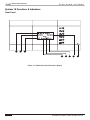
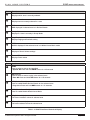
Chapter 5: Troubleshooting ............................................................................................................. 73
Appendix A: Specifications .............................................................................................................. 82
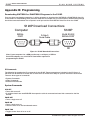
Appendix B: Programming ............................................................................................................... 84
VIA!TOOLS or ELANTOOLS Downloading to S128P ............................................................................ 84
S128P IR Codes ................................................................................................................................ 84
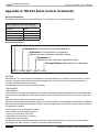
Appendix C: RS-232 Serial Control Commands .......................................................................... 90
General Information ........................................................................................................................... 90
S128P Communication Port Settings .................................................................................................. 90
RS-232 Commands ........................................................................................................................... 91
Page 6
© ELAN Home Systems 2009 • All rights reserved.
ELAN
HOME
SYSTEMS
S128P INSTALLATION MANUAL
Appendix D: Rack Mounting .......................................................................................................... 110
Warranty ................................................................................................................................ Back Page
© ELAN Home Systems 2009 • All rights reserved.
Page 7
S128P
INSTALLATION MANUAL
ELAN
HOME
SYSTEMS
Items in package:
• S128P Multi-Room A/V Controller
• Rack Mount Brackets
• Power Cord
• Installation Manual
Page 8
© ELAN Home Systems 2009 • All rights reserved.
ELAN
HOME
SYSTEMS
S128P INSTALLATION MANUAL
Chapter 1: Introduction
The S128P is the culmination of fourteen years of ELAN experience in the design and perfection of multi-source/
multi-zone controllers. Incorporating the features and reliability that has made ELAN the fastest-growing manufacturer of multi-room A/V products, the S128P is ELAN's most powerful and flexible multi-source/multi-zone controller to date. The S128P is a twelve-source eight-zone preamp controller with on-board video switching. Up to four
S128Ps can be linked for a total of thirty-two zones. The S128P can be controlled by IR or Serial commands, and
works with ELAN VIA!® Touch Panels, Olé™ Film Interactive Touchpads, keypads, and/or IR receivers, as well as
interfacing with the VIA!®SR1 Sense/Relay Module, and SS1 System Station.
This unit has been designed with ultimate flexibility in mind. Multiple control methods combine with expandability to
offer the perfect solution for larger audio/video and automation control systems. Local source inputs allow devices
located in a specific zone to be heard in and controlled from that zone, while advanced trigger options allow flexible
automation opportunities.
The S128P can switch Composite video, Component video, or both, simultaneously. High Definition video sources, like HDTV and Progressive Scan DVD players, can now be routed throughout the home as well as traditional
Composite video sources like VCRs and CCTV cameras.
The S128P is loaded with all the features a custom installer looks for in a high-end multi-room controller, including
audio/video signal sensing and system-status feedback, 12 source-specific IR ports, 2 IR 'All' ports, an External IR
Input, 6 Sense inputs, 8 Trigger outputs plus a Unit Trigger output, a Music-On-Hold output, Page/Doorbell audio
and Trigger jacks for easy integration with ELAN's C2 Communications Controller, and Serial In/Out ports for RS-232
control of the S128P. The SPP Precision Panel makes all system connections quick, neat and reliable!
The ELAN Story
Located in Lexington, KY, USA, ELAN Home Systems has designed innovative multi-room audio/video systems
since 1989. ELAN systems were the first to integrate music, intercom and TV distribution features that used the
homeowner’s stereos, televisions and telephones to create the whole-house entertainment experience. These
systems allow people to move from room to room, controlling centrally located equipment with ease.
ELAN’s product line includes:
• Power Amplifiers
• Multi-Zone Pre-Amps
• Intelligent Keypads
• In-Wall LCD Color Touch Panels
• Wireless LCD Color Touch Panels
• Film Interactive Touchpads
• In-Wall and In-Ceiling Speakers
• Outdoor Speakers
• System Controllers
• Volume Controls
• Telephone-Based Intercom Controllers
• Video Switchers
• Digital Music and DVD Management Systems
• Satellite Radios
• Accessories for Home Systems Installation
© ELAN Home Systems 2009 • All rights reserved.
Page 9
S128P
ELAN
INSTALLATION MANUAL
HOME
SYSTEMS
S128P Features
• More Sources
• 12 Audio Inputs
Connect up to 12 audio or A/V components!
• 16 Video Inputs/16 Video Outputs
• Switch independently or in synchronization w/ audio.
• Switch Composite video, Component video,
High Definition video or a combination.
• 8 Local Source Inputs
Connect a ‘private’ local source from each zone and
control it with that zone’s keypad or touch panel.
• 32 Zone Capability
Link up to 4 S128Ps to independently control up to 8, 16, 24, or 32 zones.
• Buffered Loop Outputs
Easily share sources w/ Home Theaters, etc.
• Variable & Fixed Zone Preamp Outputs
Each zone has both Variable and Fixed outputs for flexible system configuration.
• Independent Bass, Treble, Page
Volume, & Max Volume for Each Zone
Customize the sound for each zone.
• Volume and EQ Memory Retention
Keep custom settings for each zone.
• Dynamic Range Compression
Dynamic Range Compression (DRC) makes loud
audio passages quieter and quiet passages louder.
Ideal for night-time listening and Classical music.
Available independently for each zone.
• Audio & Video Source-Sensing for
System Feedback
Advanced signal sensing for source and zone
status feedback and automated sequences.
• +/- 6dB Source-Leveling
Optimize the input level of each source (including
Local source) for smooth source switching. One dB
steps for fine-tuning.
Page 10
© ELAN Home Systems 2009 • All rights reserved.
ELAN
HOME
SYSTEMS
S128P INSTALLATION MANUAL
• Advanced IR Routing
• 12 Source-specific IR Output ports
• 2 IR ‘ALL’ Output ports
• 1 External IR IN port can be routed out any
or all IR Output ports
• Blue Vacuum Fluorescent Front Panel Display
• Shows zones/sources selected, EQ, Do-Not Disturb/
Whole-House Music settings, etc.
• Display timeout & configurable Brightness
• Full ELAN Control Capability
• Use with any ELAN keypad or touch panel!
• IR or RS-232 Control
• Uses VIA!TOOLS or ELANTOOLS setup software for all programming!
• Do-Not-Disturb
Temporarily disable Page, Doorbell, WHM, and
Groups in any zone.
• Whole-House Music
Play one source throughout the house with the touch of a button.
• Groups
Link zones into one of four Groups per chassis!
• Six Sense Inputs
Trigger complex IR sequences and automated functions using VIA! Touch Panels!
• Eight Zone-Specific Triggers/One
Unit Trigger
Turn on a specific amp channel when a zone is activated or turn on the whole amp!
• Rear Panel Expansion Ports
Easily route IR and RS-485 data between multiple S128Ps.
• Rack-Mount Brackets Included
Allows S128Ps to be rack mounted
• Available in 240 Volt
For export: Models S128P240 and S128PR240
• ETL® Listed and CE® Approved
© ELAN Home Systems 2009 • All rights reserved.
Page 11
S128P
ELAN
INSTALLATION MANUAL
HOME
SYSTEMS
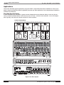
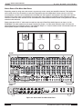
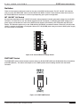
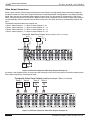
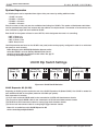
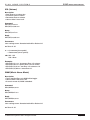
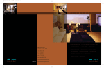
System 12 Functions & Indicators
Front Panel
A
B
C
D
E
F
1
2
3
4
5
6
7
8
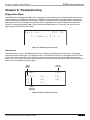
Figure 1-1: S128P Front Panel Controls & Display
Page 12
© ELAN Home Systems 2009 • All rights reserved.
ELAN
Item
HOME
SYSTEMS
Function
1
Zone Selected
Displays which zone is currently selected
2
Source Selection
Displays source currently selected in a zone
3
DND
DND displayed if selected zone is in Do-Not-Disturb
4
Group Status
Displays if a zone is currently in Group Mode
5
Page/Doorbell
Displays Paging and Doorbell activity
6
WHM
WHM is displayed if the selected zone is in Whole-House Music mode
7
Volume Status
Displays a Zone’s Volume settings
8
Power LED
Displays Power status
Item
S128P INSTALLATION MANUAL
Function
A
ZONE
Press to select a zone to be controlled
• System Off-Press and hold ZONE button for 1.25 seconds
B
SRC (Source)
Press to select a source to play in the selected zone
• Zone Off-Press and hold SRC button for 1.25 seconds
C
DND (Do-Not-Disturb)
Press to enable/disable Do-Not-Disturb for the selected zone
• Diagnostics-Press and hold DND button for 2.5 seconds
D
WHM (Whole House Music)
Press to enable/disable Whole-House Music
E
V Up (Volume Adjust)
This button increases volume in selected zone
F
V Down (Volume Adjust)
This button reduces volume in selected zone
Table 1-1: S128P Front Panel Controls & Display
© ELAN Home Systems 2009 • All rights reserved.
Page 13
S128P
ELAN
INSTALLATION MANUAL
HOME
SYSTEMS
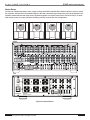
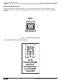
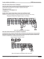
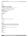
Rear Panel
1
2
3
4
5
6
7
8
9
10
11
12
13 14 15 16 17 18
19
20
21
22 23
24
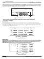
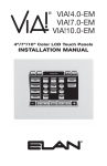
Figure 1-2: S128P Rear Panel Connections
Page 14
© ELAN Home Systems 2009 • All rights reserved.
ELAN
HOME
S128P INSTALLATION MANUAL
SYSTEMS
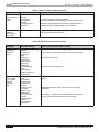
Item# Function
Item#
Function
1
Source Audio Inputs
Connect source audio
13
Page Input
Connect PG/DB Output from C2
Communications Controller
2
Source Video Inputs
Connect source Composite video
14
MOH Output
Connect to C2 MOH
(Music On Hold) Input
3
Source Video Loop Outputs
Use for shared video components
or linked chassis
15
Page Output
Connect to additional S128Ps
4
Source Audio Loop Outputs
Used for shared audio sources or
linked chassis
16
IR/RS-232 Expansion Out
Connect to SS1 or
additional S128Ps
5
Zone Video Outputs
Connect to TVs, VIA! Touch
Panels, etc.
17
IR/RS-485 Expansion In
Connect Expansion Port Out to
Expansion Port In if using
multiple S128Ps
6
Zone Audio Outputs
18
Page Trigger In/Out
7
Local Source Inputs
19
Sense Trigger Inputs
8
ELAN RS-232 Input
20
IR All Out
9
AC Power
21
Source IR Emitter Outputs
10
Unit ID Dipswitches
22
External IR Input
11
ELAN RS-232 Output
23
Chassis Trigger Output
12
Zone Keypad Inputs
24
Zone Trigger Outputs
Connect to system Amplifier.
Fixed and Variable Outputs available
Connect remotely located
“Local” sources
Connect a SS1 System Station
or SC1. Also for downloading
VIA!TOOLS or ELANTOOLS program files
Connect to AC Power
Configure Unit identity 1-4
Connect to additional S128P Chassis
Connect ELAN Keypads, VIA!s,
or IR Receivers
PG Trigger In from C2
PG Trigger Out to additional S128Ps
Connect ELAN™SENSE Sensors
for automated functions
Connect IR to system sources that
do not require source-specific IR
Source-specific IR Outputs
Connect non-system keypads or IR
receivers to control system sources
Sends a 12 VDC Trigger whenever
any zone of chassis is active
Sends a 12 VDC Trigger when a
specific zone is active
Table 1-2: S128P Rear Panel Connections
© ELAN Home Systems 2009 • All rights reserved.
Page 15
S128P
ELAN
INSTALLATION MANUAL
HOME
SYSTEMS
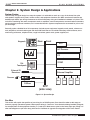
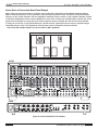
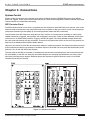
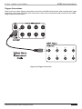
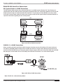
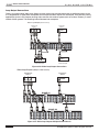
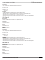
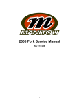
Chapter 2. System Design & Applications
System Design
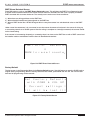
The first step to a good design is to map the system. It is advisable to mark up a copy of the house floor plan
with speaker, keypad, touch panel, volume control, and equipment locations etc. Make sure that all locations are
decided upon before pre-wiring commences so that all necessary wiring and installation hardware is in place. This
unit will be interfacing with other components such as amplifiers, source components, communications controllers,
serial controllers, and user interfaces, so it is essential that ALL system components are accounted for prior to the
pre-wire stage.
Secondly, make a detailed list of all components. Include source equipment, keypads, touch panels, volume controls, amplifiers, communications gear and the S128P itself. Be sure to include necessary electrical boxes, structured wiring enclosures, telephone lines, rough-in brackets, patch cords, power supplies, etc.
Rear
Keypads
Front
SS1
A/V Sources
TM
C2
S128P
Olé
Touchpads
External IR
Receivers
Sensors
External Amplifier
AUDIO SENSOR
SPK
Triggered
Devices
SPK
SPK
SPK
SPP
(side view)
Figure 2-1: System Design
Pre-Wire
This section will explain the specifics of pre-wiring for an S128P system. Care should be taken at this stage to
ensure a properly operational system. Most system wiring is “home-run” from the device being installed (a keypad,
for example) back to the equipment location, or “head-end”. Make sure to plan for the future when pre-wiring! It is
often advantageous to pull coax along with Cat-5 to facilitate an upgrade from keypads to VIA! Touch Panels.
Page 16
© ELAN Home Systems 2009 • All rights reserved.
ELAN
HOME
SYSTEMS
S128P INSTALLATION MANUAL
VIA! Touch Panels
• Cat-5
• 16-18 AWG 2 conductor wire (on runs greater than 110 ft.)
• RG-6 or RG-59 coaxial cable
ELAN Keypads
• Cat-5
IR Receivers
• Cat-5
Volume Controls
• Cat-5
• 16-18 AWG speaker wire
Use stranded, twisted pair speaker wire between amplifiers and volume controls, and between
volume controls and speakers. Use Cat-5 to power electronic volume controls and for volume control override when used with a C2 Communications Controller.
Speakers
• 16-18 AWG speaker wire
Use stranded, twisted pair speaker wire between amplifiers and speakers.
Local Source/LSWP
• Cat-5
Local Sources connect to the S128P using an LSWP Local Source Wall Plate with Cat-5 (see page 47).
Remotely Located Sources
• Cat-5
• RG6 or RG59 coax (if necessary)
Remotely located sources connect to the S128P
using an ELAN RSWP with Cat-5.
C2 Communications Controller
• Cat-5
When using an ELAN C2 Communications Controller, run Cat-5 for telephones. Run Cat-5 for Door Stations. See the C2 manual for details. Note that only two wires are used to connect
between the C2 and the door station. The remaining wires of the Cat-5 are used for the DSC3’s camera functions (the camera does not interact with the C2).
Serial Devices
• Cat-5 or Serial Cable
Run Cat-5 or serial cables between RS-232
controllers and the S128P.
Sense Inputs
•Cat-5 (3 conductors used)
Use Cat-5 to extend sensor leads, if necessary.
System Video
• RG-6 coax for RF or base-band video.
• RG-59 coax for base-band video only.
Use coaxial cable to distribute video to TVs and VIA! Touch Panels throughout the house.
System Audio
• RCA Interconnect Cables
© ELAN Home Systems 2009 • All rights reserved.
Page 17
S128P
ELAN
INSTALLATION MANUAL
HOME
SYSTEMS
Applications
This section describes typical applications using the S128P in audio/video/automation installations. These are all
basic in nature and should be used for guideline purposes only. Each application can be augmented as needed for
individual circumstances.
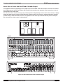
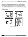
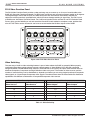
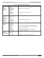
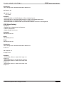
Zone/Sub-Zone Definitions
A zone is defined as an area within a system that has independent source selection ability. A zone may be one
room, or several combined areas. A sub-zone is a part of a zone - it shares source selection - but is not independent. Typically, sub-zones use volume controls for volume up/down.
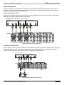
8-ZONE SYSTEM EXAMPLE
4 Stereo Zones, 2 Stereo Zones with Mono Sub-Zones, 2 Mono Zones. Total 16 amp channels used.
TM
TM
Zone 1
Zone 3
Zone 2
Zone 4
TM
Zone 5
Zone 6
Zone 7
Zone 8
S128P
D660
A12
R
SYSTEM
TRIGGER
TRIGGER INPUTS
1
_
2
LEXINGTON, KY USA • MADE IN CHINA
3
_
4
5
_
6
1
2
LEVEL
7
_
8
POWER
9
_
10
11
_
12
SPEAKER OUTPUTS 1– 12
+
1
- -
2
+
+
3
- -
4
+
+
5
- -
6
+
+
7
- -
8
+ +
9
- -
10
+
+
11
- -
12
+
AUDIO
SENSE
ON
L
1
R
LEVEL
L
R
1
2
BUS
OUT
BUS INPUT
120VAC
60Hz
440W
3
4
5
6
7
8
9
10
11
12
IN
IN
LEVEL
L
R
3
4
BUS
2
L
3
R
LEVEL
LEVEL
L
R
5
6
BUS
4
IN
L
5
R
LEVEL
IN
LEVEL
L
R
7
8
BUS
6
L
7
R
LEVEL
IN
LEVEL
L
R
9
10
BUS
8
L
9
R
LEVEL
IN
LEVEL
L
R
11
12
BUS
10
L
11
R
LEVEL
IN
BUS
12
L
R
OFF
T4.0AL
TYPE FUSE
SPEAKER INPUTS (CLASS 2 WIRING) - 40 W PER CHANNEL AT 8 OHMS
LOOP OUTPUT
1
OUT
2
3
OUT
4
5
OUT
6
7
OUT
8
9
OUT
10
11
OUT
12
Figure 2-2: 8-Zone System
Page 18
© ELAN Home Systems 2009 • All rights reserved.
ELAN
HOME
S128P INSTALLATION MANUAL
SYSTEMS
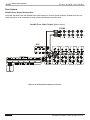
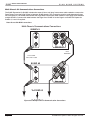
Stereo Zones
To create an independent stereo zone, simply connect the S128P’s Variable Zone Audio Outputs to a pair of amplifier channels. Volume will be controlled using IR or RS-232 commands at pre-amp level. Any and all speakers connected to these channels will ramp volume up/down together. Use a VIA! Touch Panel, Olé Touch Pad, or a handheld remote control to control functions (including volume) in zones with this configuration.
Zone 1
Zone 3
Zone 2
Zone 4
S128P
D12
POWER
1
I
O
3
2
5
4
6
IN
+
+
+
+
+
+
_
_
_
_
_
_
BUS
A
SPREAKER OUTPUTS (CLASS 2 WIRING) 75 W/CH @ 8 ohms
+
+
+
_
Txx AL FUSE
REPLACE WITH SAME
TYPE AND RATING ONLY.
_
7
8
+
+
+
_
_
9
10
+
+
+
_
_
11
12
BUS
B
IN
5
2
4
6
OUT
IN
7
9
8
10
IR
Digital Power Amplifier
ALL
ON
OUT
USB
VIA!NET
ETHERNET
OUT
IN
OUT
12
INPUT
IN
OUT
IN
11
IR
Model D12
OUT
3
IN
120 VAC 60 Hz
1440W
OUT
1
OUTPUT
+12VDC
TRIGGER
OUT
1/2
3/4
5/6
7/8
9/10
11/12
+12V TRIGGER INPUTS
Figure 2-3: Stereo Zones
© ELAN Home Systems 2009 • All rights reserved.
Page 19
S128P
ELAN
INSTALLATION MANUAL
HOME
SYSTEMS
Stereo Zone w/ Stereo Sub-Zone Fixed Output
Many areas of the home are ideal for zone/sub-zone configuration. Examples include Master Bedroom/ Master
Bath or Kitchen/Dining Area. In this application, only two amp channels are used. Connect the Fixed Zone Audio
Output to a pair of amp channels. Use two impedance matching volume controls on the amplifier’s speaker outputs
to maintain independent volume control capabilities in each room. At least one controlling device (touch pad, touch
panel) must be installed to control the zone. Volume up/down will be controlled with the volume control located
in each part of the zone. If using ELAN electronic volume controls, system and source control is possible using a
hand-held remote control. This application uses the least amount of amplifier channels possible.
Note: Fixed Zone Audio Outputs do not have DRC or EQ capabilities.
Zone 1
S128P
D660
Figure 2-4: Stereo Sub-Zone Fixed Output
Page 20
© ELAN Home Systems 2009 • All rights reserved.
ELAN
HOME
S128P INSTALLATION MANUAL
SYSTEMS
Stereo Zone w/ Stereo Sub-Zone Fixed & Variable Output
This application takes full advantage of the S128P’s Fixed and Variable Zone Audio Outputs. The main zone utilizes
the Variable outputs. An Olé Touch Pad or VIA! Touch Panel controls source selection, source control, etc. and volume up/down in the main zone.
The sub-zone uses a volume control to ramp volume up/down independently from the main zone, however, it always
shares the same source. If using an ELAN electronic volume control in the sub-zone, system and source control is
possible using a hand-held remote control. This application uses more amp channels than the previous example,
but only uses one volume control in the sub-zone.
Zone 1
Olé or VIA!
Volume Control
S128P
A12
R
SYSTEM
TRIGGER
TRIGGER INPUTS
1
_
2
LEXINGTON, KY USA • MADE IN CHINA
3
_
4
5
_
6
1
2
LEVEL
7
_
8
POWER
9
_
10
11
_
12
SPEAKER OUTPUTS 1– 12
+
1
- -
2
+
+
3
- -
4
+
+
5
- -
6
+
+
7
- -
8
+ +
9
- -
10
+
+
11
- -
12
+
AUDIO
SENSE
ON
L
1
R
LEVEL
L
R
1
2
BUS
OUT
BUS INPUT
120VAC
60Hz
440W
3
4
5
6
7
8
9
10
11
12
IN
IN
LEVEL
L
R
3
4
BUS
2
L
3
R
LEVEL
IN
LEVEL
L
R
5
6
BUS
4
L
5
R
LEVEL
IN
LEVEL
L
R
7
8
BUS
6
L
7
R
LEVEL
IN
LEVEL
L
R
9
10
BUS
8
L
9
R
LEVEL
IN
LEVEL
L
R
11
12
BUS
10
L
11
R
LEVEL
IN
BUS
12
L
R
OFF
T4.0AL
TYPE FUSE
SPEAKER INPUTS (CLASS 2 WIRING) - 40 W PER CHANNEL AT 8 OHMS
LOOP OUTPUT
1
OUT
2
3
OUT
4
5
OUT
6
7
OUT
8
9
OUT
10
11
OUT
12
Figure 2-5: Stereo Sub-Zone Fixed & Variable Output
© ELAN Home Systems 2009 • All rights reserved.
Page 21
S128P
ELAN
INSTALLATION MANUAL
HOME
SYSTEMS
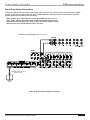
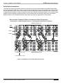
Stereo Zone w/Two Stereo Sub-Zones
This application is ideal for large areas where independent volume control is needed. Volume is controlled in a variable zone using touch pads or touch panels. Sources for the entire zone are selected and controlled from this same
keypad or touch panel.
Connect the Fixed Zone Audio Outputs to two impedance matching volume controls, then to two pairs of speakers.
The volume controls will ramp volume up/down for only the speakers that they are connected to, giving separate
volume control in all areas of the zone. If using electronic volume controls, a hand-held IR remote control can be
used for source select and control in the sub-zone areas. If using rotary volume controls, all source selection and
control must be done from the keypad or touch panel.
This application has cost-saving advantages. Only two pairs of amp channels are needed. If using electronic volume controls, independent volume up/down is available as well as source selection and control. In this application,
separate source selection is only available in one area.
Zone 1
S128P
D12
POWER
1
I
O
3
2
5
4
6
IN
+
+
+
+
+
+
_
_
_
_
_
_
BUS
A
OUT
SPREAKER OUTPUTS (CLASS 2 WIRING) 75 W/CH @ 8 ohms
+
+
_
Txx AL FUSE
REPLACE WITH SAME
TYPE AND RATING ONLY.
+
+
+
_
_
7
+
_
9
8
10
+
+
+
_
_
11
12
BUS
B
5
2
4
6
OUT
IN
7
9
8
10
IR
ALL
ON
OUT
USB
VIA!NET
ETHERNET
OUT
IN
OUT
12
INPUT
IN
OUT
IN
11
IR
Model D12
Digital Power Amplifier
OUT
3
IN
120 VAC 60 Hz
1440W
IN
1
OUTPUT
+12VDC
TRIGGER
OUT
1/2
3/4
5/6
7/8
9/10
11/12
+12V TRIGGER INPUTS
Figure 2-6: Two Stereo Sub-Zones
Page 22
© ELAN Home Systems 2009 • All rights reserved.
ELAN
HOME
S128P INSTALLATION MANUAL
SYSTEMS
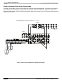
Stereo Zone w/ Mono Sub-Zone
Mono speakers are often used in areas that do not have a distinct listening area such as a basement or kitchen.
This application provides source selection, source control and volume up/down from a touch pad or touch panel in
the main zone, and volume up/down in the sub-zone. If using an electronic volume control in the sub-zone, source
select and zone control are available by using a hand-held IR remote control.
Zone 1
Volume Control
Olé or VIA!
S128P
A12
R
SYSTEM
TRIGGER
TRIGGER INPUTS
1
_
2
LEXINGTON, KY USA • MADE IN CHINA
3
_
4
5
_
6
1
2
LEVEL
7
_
8
POWER
9
_
10
11
_
12
SPEAKER OUTPUTS 1– 12
+
1
- -
2
+
+
3
- -
4
+
+
5
- -
6
+
+
7
- -
8
+ +
9
- -
10
+
+
11
- -
12
+
AUDIO
SENSE
ON
L
1
R
LEVEL
L
R
1
2
BUS
OUT
BUS INPUT
120VAC
60Hz
440W
3
4
5
6
7
8
9
10
11
12
IN
IN
LEVEL
L
R
3
4
BUS
2
L
3
R
LEVEL
IN
LEVEL
L
R
5
6
BUS
4
L
5
R
LEVEL
IN
LEVEL
L
R
7
8
BUS
6
L
7
R
LEVEL
IN
LEVEL
L
R
9
10
BUS
8
L
9
R
LEVEL
IN
LEVEL
L
R
11
12
BUS
10
L
11
R
LEVEL
IN
BUS
12
L
R
OFF
T4.0AL
TYPE FUSE
SPEAKER INPUTS (CLASS 2 WIRING) - 40 W PER CHANNEL AT 8 OHMS
LOOP OUTPUT
1
OUT
2
3
OUT
4
5
OUT
6
7
OUT
8
9
OUT
10
11
OUT
12
Figure 2-7: Stereo Zone with Mono Sub-Zone
© ELAN Home Systems 2009 • All rights reserved.
Page 23
S128P
ELAN
INSTALLATION MANUAL
HOME
SYSTEMS
Stereo Zone w/Two Mono Sub-Zones
Expanding zones by using mono sub-zones is a great way to save money and amplifier channels. This application
uses a total of four amp channels to create three separate areas with independent volume control. As in previous examples, a source can be selected and controlled from the keypad or touch panel in the main zone. Volume
up/down in the main zone is controlled the same way. Sub-zone volume is controlled from the individual volume
controls in each sub-zone. Sources can be controlled from a hand-held IR remote control if using electronic volume
controls in the sub-zone.
Please note that an RCA ‘Y’ cable must be used from the zone’s Fixed Zone Audio Output to an Input 1 L of an
ELAN D660. This cable creates a mono signal. Connect the Output 1 L of the same Channel to Input 1 R. Now, the
same audio plays out of Speaker Output 1 R and Speaker Output 1 L. A mono volume control is connected to each of
these speaker outputs to create two mono sub-zones.
Zone 1
Olé or VIA!
Volume Control
Volume Control
S128P
D660
Figure 2-8: Stereo with Two Mono Sub-Zones
Page 24
© ELAN Home Systems 2009 • All rights reserved.
ELAN
HOME
S128P INSTALLATION MANUAL
SYSTEMS
Chapter 3. Connections
System Control
System control connections are comprised of IR Inputs, IR Emitter Outputs, IR/RS485 Expansion ports, RS232
ports, and Triggers. These various control methods can be combined and integrated to create hundreds of possible
control schemes for customized functionality.
SPP Precision Panel
The SPP Precision Panel is more than a convenient trim-out solution for the S128P. With more sources, more zones
and more built-in features than any other ELAN multi-room controller to date, the number of wire runs and systems
connections needed to get everything up and running smoothly makes the SPP a necessity!
The rear panel of the SPP features a neatly laid out array of all the 110 punch-downs necessary to ensure quick,
reliable connection of keypads, touch panels, and touchpads in every zone. There are also dedicated punch-down
connectors for six ELAN™Sense sensors, Triggers, and EXT IR signals. The clearly labeled overlays shows both
the color-code and function of every connection. There are RJ-45 jacks and a switch on the rear of the panel for an
easy link to an additional SPP, and SS1 System Station.
Use one or two meter RJ-45-to-RJ-45 interconnect cables for reliable connections. Six Sense Input jacks use stereo
3.5mm interconnect cables to go directly to the Sense Inputs on the S128P. The front panel also features DC power
jacks for 1.5A, 4A and 10A VIA! power supplies .
The front panel of the SPP is removable, to facilitate easy access when connecting wires. New-construction brackets are available, or the SPP can easily be retro-fitted using the four clamping legs attached to the frame, which
secure the panel securely to drywall. Additional panels are required for systems with two, three or four S128P
Controllers (one SPP per chassis).
Figure 3-1: SPP Precision Panel
© ELAN Home Systems 2009 • All rights reserved.
Page 25
S128P
ELAN
INSTALLATION MANUAL
HOME
SYSTEMS
Connections When Using an ELAN SPP
System Precision Panel - Rear
NOTE: Prior to making any connections on the SPP, place the
appropriate overlay on the rear of the Precision Panel for the
system type that is being installed.
Figure 3-2: SPP “S6 / S12” Overlay
NOTE: On the SPP, the "A" and "B" punchdown locations for RS
485 are always V-Net 485, NOT Z-Net. Connect any Z-Net 485
to the RS 485 expansion block of the SPP Precision Panel to
obtain proper feedback.
Page 26
© ELAN Home Systems 2009 • All rights reserved.
ELAN
HOME
S128P INSTALLATION MANUAL
SYSTEMS
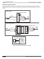
VIA! Touch Panel Connections
The S128P is designed to work flawlessly with ELAN VIA! Touch Panels. VIA! Touch Panels require ELAN 16 Volt
DC power supplies. Use the PWR10 16V/10A power supply to power up to ten VIA! Touch Panels. Use the PWR4
16V/4A power supply to power up to 4 VIA! Touch Panels. Use the PWR1 16V/1.5A power supply to power a single
touch panel.
When using a VIA! Valet 100EM Tabletop/Under-Cabinet Color Touch Panel, a PVIA1 Valet Wall Plate must be used.
One PVIA Wall Plate is included with each VIA! Valet. The installer has the option of using the included PVIA1 power
supply, or one of the other 16V power supplies to provide power to the Valet.
VIA! Touch Panels punch-down to the rear of the SPP at two locations, depending on system configuration. These
locations are labelled “ZXA 16V VIA!/OLÉ” and “ZXB 16V/12V VIA!/OLÉ” where “X” corresponds to the zone that the
touch panel(s) will control. Two touch panels can connect to each punch-down location for each zone. If using more
than 2 touch panels per location, make connections off of the SPP and use jumper wires to punch-down to the correct location. Figure 3-4 shows the correct wiring for one touch panel in Zone 1 connected to the “A” location and
utilizing 16VDC power from the PWR1, PWR4, or PWR10 power supply connected to the front of the SPP.
SPP to VIA! Touch Panel
N/C
IR
Blue
White/Blue
Orange
White/Orange
Green
White/Green
Brown
White/Brown
485485+
G
16V
G
16V
Butt splice
or equivalent
Cat-5
SPP to PVIA1VALET (Using 16 VDC from SPP)
N/C
IR
Blue
White/Blue
Orange
White/Orange
Green
White/Green
Brown
White/Brown
485485+
G
16V
G
16V
Cat-5
Blue
White/Blue
Orange
White/Orange
Green
White/Green
Brown
White/Brown
SPP to PVIA1VALET (Using 16 VDC from PVIA1)
N/C
IR
485485+
G
16V
G
16V
X
X
Blue
White/Blue
Orange
White/Orange
Green
White/Green
Brown
White/Brown
Cat-5
Blue
White/Blue (IR)
Orange (485-)
White/Orange (485+)
Green (GND)
White/Green (+16V)
Brown (GND)
White/Brown (+16V)
Blue
White/Blue
Orange
White/Orange
Green
White/Green
Brown
White/Brown
Blue
White/Blue
Orange
White/Orange
Green
White/Green
Brown
White/Brown
When connecting a PVIA1 Valet
Wall Plate to the SPP, use either the
included PVIA1 power supply connected
to the PVIA1 Wall Plate, or a PWR10,
PWR4 or PWR1 power supply connected
to the SPP.
DO NOT USE BOTH POWER SUPPLIES!
nc
nc
nc
nc
nc
nc
X
X
PVIA-1
SIR
Z485Z485+
ST/SNS
IR
V485V485+
GND
+16V
GND
+16V
PVIA-1
SIR
Z485Z485+
ST/SNS
IR
V485V485+
GND
+16V
GND
+16V
nc
nc
nc
Blue
White/Blue
Orange
White/Orange
Green
White/Green
Brown
White/Brown
nc
nc
nc
Blue
White/Blue
Orange
White/Orange
Green
White/Green
Brown
White/Brown
VIA!
Touch
Panel
VIA!
Touch
Panel
VIA!
Touch
Panel
IMPORTANT NOTE
Olé Touchpads
and VIA! Touch Panels
Use the correct power
supply connected to the front
of the SPP for the number
of Olé Touchpads and VIA!
Touch Panels in the system.
Olé = 150mA
VIA! = 1A
PWR1 = 1.5A
PWR4 = 4A
PWR10 = 10A
Figure 3-3: VIA! Touch Panel Connections
© ELAN Home Systems 2009 • All rights reserved.
Page 27
S128P
ELAN
INSTALLATION MANUAL
HOME
SYSTEMS
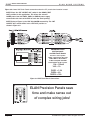
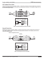
Figure 3-4 shows VIA! Touch Panel connections when the “B” punch-down location is used.
NOTE: Place the “INT 12V/EXT 16V” switch in the DOWN (“EXT
16V”) position for this application. This allows the external
16VDC power from the PWR1, PWR4, or PWR10 power supply
connected to the front of the SPP to reach the touch panel(s).
NOTE: Refer to Figure 3-3 for VIA! Valet100EM connectivity. The “INT
12V/EXT 16V” switch will be in the “EXT 16V” position as
shown in Figure 3-3.
IMPORTANT NOTE
IMPORTANT NOTE
Olé Touchpads
Olé Touchpads
and VIA! Touch
UsePanels
the correct power
supply
connected
to the front
Use the correct power
of
the
SPP
for
the
number
supply connected to the front
or the
Olénumber
Touchpads and VIA!
of the SPP for
Touch and
Panels
of Olé Touchpads
VIA! in the system.
Touch Panels in the system.
Olé = 150mA
VIA! = 1A
PWR1 = 1.5A
PWR4 = 4A
PWR10 = 10A
Figure 3-4: VIA! Touch Panel Connections
VIA!NET
EXT IR
TO SENSE INPUTS
1
2
SS/SC4
3
USE STEREO 3.5mm PLUGS ONLY
4
5
6
ZONE
ZONE
1
5
TRIGGERS
1
2
3
4
5
6
7
8
ZONE
2
ZONE
3
ZONE
4
ZONE
POWER
+
--
16VDC / 10A
16VDC / 4A
16VDC/1.5A
Page 28
6
ZONE
7
ZONE
8
ELAN Precision Panels save
time and make sense out
of complex wiring jobs!
© ELAN Home Systems 2009 • All rights reserved.
ELAN
HOME
SYSTEMS
S128P INSTALLATION MANUAL
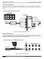
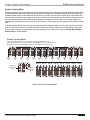
Olé Film Interactive Touchpads
Olé Film Interactive Touchpads punch-down to the rear of the SPP at three locations, depending on system configuration. These locations are labelled “ZXA 16V VIA!/OLÉ”, “ZXB 16V/12V VIA!/OLÉ” and “ZXC 12V OLÉ/ZPAD” where
“X” corresponds to the zone that the touchpad(s) will control. Touchpads can connect to each punch-down location
for each zone. If using more than 2 touchpads per location, make connections off of the SPP and use
jumper wires to punch-down to the correct location.
“A” Punchdown Locations
Figure 3-5 shows connectivity to the “A” location and utilizing 16VDC power from a PWR1, PWR4, or PWR10
16VDC power supply connected to the front of the SPP.
NOTE: The “A” punchdown location is always connected to the
external 16VDC power from a PWR1, PWR4, or PWR10 16VDC
power supply connected to the front of the SPP.
IMPORTANT NOTE
Olé Touchpads
Use the correct power
supply connected to the front
of the SPP for the number
or Olé Touchpads and VIA!
Touch Panels in the system.
Figure 3-5: Olé Touchpad “A” External 16VDC Connections
© ELAN Home Systems 2009 • All rights reserved.
Page 29
S128P
ELAN
INSTALLATION MANUAL
HOME
SYSTEMS
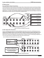
“B” Punchdown Locations-16V
Figure 3-6 shows connectivity to the “B” location and utilizing 16VDC power from a PWR1, PWR4, or PWR10
16VDC power supply connected to the front of the SPP.
NOTE: Place the “INT 12V/EXT 16V” switch in the DOWN (“EXT
16V”) position for this application.
IMPORTANT NOTE
Olé Touchpads
Use the correct power
supply connected to the front
of the SPP for the number
or Olé Touchpads and VIA!
Touch Panels in the system.
Figure 3-6: Olé Touchpad “B” External 16VDC Connections
Page 30
© ELAN Home Systems 2009 • All rights reserved.
ELAN
HOME
S128P INSTALLATION MANUAL
SYSTEMS
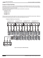
“B” Punchdown Locations-12V
The SPP Precision panel has the ability to connect touchpanels, keypads and Olé Touchpads in various
combinations in each zone. The “B” punchdown location can either pass 12VDC power from the S128P Controller
(Internal Power) or 16VDC from a power supply connected to the front of the SPP (External). Figure 3-7 shows
connectivity to the “B” location and utilizing internal 12VDC power from the S128P Multi-Room Controller.
NOTE: Place the “INT 12V/EXT 16V” switch in the UP (“INT 12V”)
position for this application.
Olé Touchpad to SPP Precision Panel (Using 12VDC from S128P)
IMPORTANT NOTE
Olé Touchpads
Use the correct power
supply connected to the front
of the SPP for the number
or Olé Touchpads and VIA!
Touch Panels in the system.
Figure 3-7: Olé Touchpad “B” Internal 12VDC Connections
VIA!NET
EXT IR
TO SENSE INPUTS
1
2
SS/SC4
3
USE STEREO 3.5mm PLUGS ONLY
4
5
6
ZONE
ZONE
1
5
TRIGGERS
1
2
3
4
5
6
7
8
ZONE
2
ZONE
3
ZONE
4
ZONE
POWER
+
6
ZONE
--
16VDC / 10A
16VDC / 4A
16VDC/1.5A
7
ZONE
8
ELAN Precision Panels save
time and make sense out
of complex wiring jobs!
© ELAN Home Systems 2009 • All rights reserved.
Page 31
S128P
ELAN
INSTALLATION MANUAL
HOME
SYSTEMS
“C” Punchdown Locations
Figure 3-8 shows connectivity to the “C” location and utilizing internal 12VDC power from the S128P Multi-Room
Controller.
Olé Touchpad to SPP Precision Panel (Using 12VDC from S128P)
Butt splice
or equivalent
N/C
W/BL
N/C
N/C
N/C
W/GR
BR
N/C
Blue
White/Blue
Orange
White/Orange
Green
White/Green
Brown
White/Brown
Cat-5
Blue
White/Blue
Orange
White/Orange
Green
White/Green
Brown
White/Brown
Blue
White/Blue (IR)
Orange(Local IR)
White/Orange (485+)
Green (485-)
White/Green (+12V)
Brown (GND)
White/Brown
RS 485 Expansion
White/Orange
W/OR
Green
GR
White/Orange
W/OR
Green
GR
White/Orange
W/OR
Green
GR
White/Orange
W/OR
Green
GR
IMPORTANT NOTE
Olé Touchpads, Keypads
VSEs, & IR
Each ZONE INPUT
RJ-45 Jack on the S66A
Provides 12 VDC 300mA
When using the internal 12VDC power
from the S66A, you may choose to
load each of the S66A’s ZONE INPUTS
with any combination of Olé
Touchpads, IR Receivers,
or Electronic Volume Controls
as long as the total current consumption
DOES NOT EXCEED 300mA.
Olé = 150mA
Keypad w/IR Tube = 65mA
Z•025 = 85mA
Electronic Volume Control = 40mA
Additional IR Receivers = 10mA
Figure 3-8: Olé Touchpad “C” Internal 12VDC Connections
Z•Pad Connections
“C” Punchdown Locations
Figure 3-9 shows there are two methods available when connecting keypads as zone controllers in an S128P
based system. If using more than 2 keypads per location, make connections off of the SPP and use jumper wires to
punch-down to the correct location.
Method A-VNET (Using an SS1/SC-1)
Punch the 485+ (Wh/Orange) and 485- (Green) wires down to the RS 485 Expansion block located below the SS/
SC4 switch as shown on the S6/S12 Overlay.
Method B-ZNET (No SS1/SC-1)
Remove the S6/S12 Overlay. Punch the 485+ (Wh/Orange) to the 485+ location on the SPP and punch the 485(Green) wire to the 485- location on the SPP as shown below.
Page 32
© ELAN Home Systems 2009 • All rights reserved.
ELAN
HOME
S128P INSTALLATION MANUAL
SYSTEMS
Keypad to SPP Precision Panel (Using 12VDC from S128P)
Method A
N/C
W/BL
N/C
N/C
N/C
W/GR
BR
N/C
Butt splice
or equivalent
Blue
White/Blue
Orange
White/Orange
Green
White/Green
Brown
White/Brown
Cat-5
Blue
White/Blue
Orange
White/Orange
Green
White/Green
Brown
White/Brown
Blue
White/Blue (IR)
Orange(Local IR)
White/Orange (485+)
Green (485-)
White/Green (+12V)
Brown (GND)
White/Brown
RS 485 Expansion
White/Orange
W/OR
Green
GR
White/Orange
W/OR
Green
GR
White/Orange
W/OR
Green
GR
White/Orange
W/OR
Green
GR
Method B
Z1C 12V OLÉ/ZPAD
Blue
N/C
IR
White/Blue
485Orange
485+
White/Orange
N/C
Green
12V
White/Green
G
Brown
N/C
White/Brown
Butt splice
or equivalent
Cat-5
Blue
White/Blue
Orange
White/Orange
Green
White/Green
Brown
White/Brown
Blue
White/Blue (IR)
Orange(Local IR)
White/Orange (485+)
Green (485-)
White/Green (+12V)
Brown (GND)
White/Brown
Figure 3-9: Z•Pad Connections
IR Receiver Connections
Stand-alone IR receivers for use with hand-held remotes can easily connect to the SPP “C" punchdown locations.
Connect +12V, IR, and GND to the specific zone that is to be controlled.
Figure 3-10: IR Receiver Connections
© ELAN Home Systems 2009 • All rights reserved.
Page 33
S128P
ELAN
INSTALLATION MANUAL
HOME
SYSTEMS
Sense Input Connections
The Sense Trigger Inputs of the S128P are primarily for use with VIA! Touch Panels and Olé Touchpads. An
ELAN™SENSE Sensor can be connected that will cause VIA! Touch Panels and Olé Touchpads to execute IR or
serial commands. Use VIA!TOOLS or ELANTOOLS setup software to program Trigger Input functionality. Wiring the
Sense Inputs consists of punching down Voltage (V), Sense (S), and Ground (G) as shown in Figure 3-11.
Head End
RJ-45
Wall Plate
Butt splice
or equivalent
Cat-5
Cat-5
Butt splice
or equivalent
Figure 3-11: Sense Input to SPP Connections
ELAN™SENSE Sensors provide for a multitude of automation requirements:
• Audio Sensor: Detects line-level audio utilizing an RCA adaptor.
• Video Sensor: Detects Composite video utilizing an RCA adaptor.
• Light/LED Sensor: Detects ambient light or multi-color LEDs.
• Contact Closure Sensor: Detects closed-contact ON/OFF status.
• Current/Magnetic Sensor: Detects electrical current through power cords or
magnetic flyback.
• Voltage Sensor: Detects 3-24 Volts AC or DC. Doorbell Sensor: Detects multiple
doorbell signals for advanced switching functionality.
Programmable Trigger Connections
Devices that are remotely located can utilize the SPP’s Triggers Connections in order to receive signals based
on zone activation or system activation. The Programmable Trigger outputs can be controlled using IR or Serial
Commands. Examples include remotely located amplifiers and/or power controllers.
Figure 3-12: Programmable Trigger Connections
Page 34
© ELAN Home Systems 2009 • All rights reserved.
ELAN
HOME
S128P INSTALLATION MANUAL
SYSTEMS
LINK IN/LINK OUT Connections
Use the LINK IN and LINK OUT RJ-45 connectors to link multiple S128P chassis and multiple SPP Precision Panels.
Use an RJ-45 to RJ-45 Interconnect cable from the LINK IN jack of the first SPP Panel to the LINK IN jack of the
second SPP Panel and so on.
Figure 3-13: Link In/Link Out Connections
© ELAN Home Systems 2009 • All rights reserved.
Page 35
S128P
ELAN
INSTALLATION MANUAL
HOME
SYSTEMS
External Power Connections
Use the V+ and G screw terminal connections at the bottom edge of the SPP Precision Panel to connect 2
conductor wires (14-18AWG) to power VIA! Touch Panels that DO NOT use the Cat-5 power wiring option at the
touch panel and DO use the external power connector located on the touch panel. This application is typically used
for long wire runs greater than 110 feet in length. It is not necessary to use both the Cat-5 power connection
(located on the ZONE punchdown locations) and the External Power connectors described here.
VIA!70
External
Power
Connector
Figure 3-14: External Power Connections
RS-485 Expansion Connections
The RS-485 EXPANSION punchdown connectors channel RS-485 signals (ZNET) generated by the multi-room
controller. The RS-485 information sent to these punchdowns is identical to that sent to the ZONE locations
(Z#C). The RS-485 EXPANSION locations simply allow additional punchdown positions and typically WILL BE
needed when installing touch panels, touchpads, and keypads in an S128P system.
NOTE: The S128P Controller, generates ZNET information for status
feedback. Make sure to set the ZNET/VNET switch to the ZNET
position in any S128P-based system.
+
+
+
+
Figure 3-15: RS-485 Expansion Connections
Page 36
© ELAN Home Systems 2009 • All rights reserved.
ELAN
HOME
S128P INSTALLATION MANUAL
SYSTEMS
Switches
There are three types of switches located on the rear of the SPP Precision panel: The INT 12V-EXT 16V switches
(one per zone), the ZNET/VNET switch and the SS/SC4-NO SS/SC-4 switch. These switches affect the function of
the S128P Multi-Room Controller in various ways depending upon system configuration.
INT 12V-EXT 16V Switch
As previously described, the INT 12V-EXT 16V switch selects between internally generated voltage from the S128P
Controller (+12 Volts DC) for use with Z•Pad Keypads and Olé Touchpads, or externally generated voltage from a
power supply connected to the front of the SPP Precision Panel to be utilized by Olé Touchpads and VIA! Touch
Panels. This selection applies only to the “Z#B 16V/12V OLÉ/ZPAD” punchdown location. Select INT 12V (UP) when
12VDC is required for keypads or touchpads. Selects EXT 16V (DOWN) when using an external 16VDC power supply
for touch panels or touchpads.
Figure 3-16: Internal/External Voltage Switch
ZNET/VNET Switch
The ZNET-VNET switch selects between systems based on ELAN’s ZNET (S66A and S128P Multi-Room Controllers)
and VNET (S86A/P ). This switch will always be in the ZNET position when installing the SPP with the S128P
Controller.
Figure 3-17: ZNET/VNET Switch
© ELAN Home Systems 2009 • All rights reserved.
Page 37
S128P
ELAN
INSTALLATION MANUAL
HOME
SYSTEMS
SS/SC4-NO SS/SC4 Switch
If the system contains an SS1 System Station or SC-1 Serial Controller, set this switch to the SS/SC4* position.
If the system does not contain an SS1 System Station or SC-1 Serial Controller, set the switch to the NO SS/SC4
position.
Figure 3-18: SS/SC4-No SS/SC4 Switch
*Note: The ELAN SC-4 is a discontinued product.
Page 38
© ELAN Home Systems 2009 • All rights reserved.
ELAN
HOME
S128P INSTALLATION MANUAL
SYSTEMS
Connections When Using an ELAN
SPP System Precision Panel - Front
VIA!NET Connection
This RJ-45 connector is used for configuring multiple SS1 configurations. See the VIA!TOOLS or ELANTOOLS Help
file for additionl information about configuring multiple SS1's.
Figure 3-19: VIA!NET Connection (Future Use)
EXT IR Connections
The External IR Input is a powerful feature that can enable specialized functionality in situations where system-wide
(not zone-specific) IR control is required. Connect a 3.5mm mono interconnect cable between EXT IR of the SPP
and EXT IR IN of the S128P.
Figure 3-20: EXT IR Connection (Not Used)
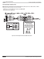
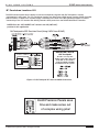
Sense Input Connections
Information from ELAN™SENSE Sensors connected to the S128P’s ELAN SENSE INPUTS is used to trigger events
that have been programmed into VIA! Touch Panels. Typically, sensors will connect to the back of the SPP Precision
Panel, then 3.5mm stereo interconnect cables will be used between the Precision Panel’s TO SENSE INPUTS jacks
and the S128P Controller’s ELAN SENSE INPUTS jacks. Utilize VIA!TOOLS or ELANTOOLS Setup Software to create
IR or serial command strings for automated functions. See the VIA!TOOLS or ELANTOOLS Help file for additional
information about programming Sense Inputs.
S128P
Figure 3-21: Sense Input Connections
© ELAN Home Systems 2009 • All rights reserved.
Page 39
S128P
ELAN
INSTALLATION MANUAL
HOME
SYSTEMS
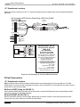
SS/SC4 Connection
Use the SS/SC4 RJ-45 connector to integrate an ELAN SS1 System Station or SC-4 System Controller to the S128P
Multi-Room Controller in order to facilitate integration of RS-232 controlled systems such as security, lighting or
HVAC. Use an RJ-45 Interconnect Cable for this purpose.
Figure 3-22: SS/SC4
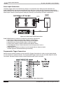
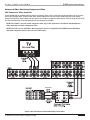
ZONE 1-8 Connections
Connect a straight-through RJ-45 interconnect cable (RJ-45 1 or 2 meter Interconnect Cable) between the S128P’s
1-8 Zone Inputs and the SPP Zone 1-8 RJ-45 jacks. This routes all keypads, touch panels, touchpads and IR receivers punched-down on the back of the SPP directly to the S128P.
NOTE: In order to facilitate RS-485 communication, Zone 1 must
ALWAYS be connected between the S128P Controller and the
SPP Precision Panel.
SPP to S128P Zone Keypad Connections (Zone 1 shown)
SPP
ZONE
S128P
1
Figure 3-23: Zone Keypad Input Connections
Page 40
© ELAN Home Systems 2009 • All rights reserved.
ELAN
HOME
S128P INSTALLATION MANUAL
SYSTEMS
Triggers Connections
There are 8 mono 3.5mm Triggers connections on the front of the SPP Precision Panel. After punching down trigger
connections on the back of the SPP, use a 3.5mm mono ‘mini-to-mini’ interconnect cable to connect to the S128P
Trigger Outputs as shown below.
S128P
Figure 3-24: Triggers Connection
© ELAN Home Systems 2009 • All rights reserved.
Page 41
S128P
ELAN
INSTALLATION MANUAL
HOME
SYSTEMS
Power Connections
It is possible to connect and power up to ten VIA! Touch Panels using the SPP and a 16VDC power supply. Use
punchdown locations “A” and “B” and place the INT V-EXT V switch in the EXT position for each zone that utilizes 16VDC from the connected power supply. Use an ELAN PWR1 16VDC/1.5A power supply for one VIA! Touch
Panels. Use an ELAN PWR4 16VDC/4A power supply for up to four VIA! Touch Panels. Use an ELAN PWR10
16VDC/10A power supply for five-to-ten VIA! Touch Panels. It is also possible to connect up to 66 Olé Touchpads
using the same 16VDC power supplies. A PVIA1 will power up to 6 Olé Touchpads, a PVIA4 can power up to 26 Olé
Touchpads and a PVIA10 Power Supply can support 66 Olé Touchpads. A combination of VIA! Touch panels and Olé
Touchpads can be accomodated. Please consult the chart below for maximum current draw of each device.
NOTE: Only one power supply should be connected to the SPP
Precision Panel at any time!
Figure 3-25: SPP Power Connections
Page 42
© ELAN Home Systems 2009 • All rights reserved.
ELAN
HOME
S128P INSTALLATION MANUAL
SYSTEMS
S128P Connections When NOT Using a
System Precision Panel
Sense Trigger Input Connections
Information from ELAN™SENSE Sensors connected to the S128P’s Sense Trigger Inputs is used to trigger events
that have been programmed into VIA! Touch panels. To connect ELANSense sensors directly to the S128P, simply plug the 3.5 mm stereo interconnect cable of the Sensor into the desired Sense Trigger Input. If long runs
are required, the 3.5 mm stereo interconnect cable must be cut off and the cable extended using Cat-5. Utilize
VIA!TOOLS or ELANTOOLS setup software to create IR or serial command strings for automated functions. See
VIA!TOOLS or ELANTOOLS Help for additional information about programming Sense Triggers.
ELAN™SENSE Sensor to S128P Sense Trigger Inputs
S128P
AUDIO SENSOR
Figure 3-26: Sense Trigger Input Connections
© ELAN Home Systems 2009 • All rights reserved.
Page 43
S128P
ELAN
INSTALLATION MANUAL
HOME
SYSTEMS
VIA! Touch Panel Connections
If not using the SPP, it is necessary to use a PVIA Wall Plate when connecting VIA! Touch Panels to the S128P.
VIA! Touch Panels require the 16V power supplies that are included with each PVIA wall plate (PVIA1, PVIA4, and
PVIA10).
S128P to PVIA1
PVIA1 (No SC1, SC4, or SS1)
To S128P
Blue
White/Blue
Green
White/Orange
Brown
SIR
Z485Z485+
ST/SNS
IR
V485V485+
GND
+16V
GND
+16V
N/C
N/C
N/C
Blue
White/Blue
Orange
White/Orange
Green
White/Green
Brown
White/Brown
To VIA!
Touch
Panel
S128P to PVIA4/PVIA10
PVIA4/PVIA10 (Zone 1 Connection Shown)
To S128P
Zone 1
ST1
ST2
ST3
ST4
Z485+
Z485SIR
GND
White/Blue
White/Orange
Green
Brown
IR1
GND
IR2
GND
IR3
GND
IR4
GND
IR
XLINK
+16V
GND
+16V
GND
485+
485IR
ST/SNS
White/Brown
Brown
White/Green
Green
White/Orange
Orange
White/Blue
Blue
To VIA!
Touch
Panel
VIA1
Standard ELAN RJ-45 Pin-Out
FRONT
PIN # COLOR CODE
1
2
3
4
5
6
7
8
TA B
BLUE
WHITE/BLUE
ORANGE
WHITE/ORANGE
GREEN
WHITE/GREEN
BROWN
WHITE/BROWN
CABLE
Figure 3-27: VIA! Touch Panel Connections (No SPP)
Page 44
© ELAN Home Systems 2009 • All rights reserved.
ELAN
HOME
S128P INSTALLATION MANUAL
SYSTEMS
Olé Touchpad Connections
ELAN Olé Touchpads require IR, RS-485+, RS-485-, 12 Volts DC, and Ground to function. Make these connections
as shown below. Multiple keypads in the same zone require parallel connections. For simplicity, all eight wires can
be connected straight through.
S128P
Standard ELAN RJ-45 Pin-Out
FRONT
PIN # COLOR CODE
1
2
3
4
5
6
7
8
TAB
BLUE
WHITE/BLUE
ORANGE
WHITE/ORANGE
GREEN
WHITE/GREEN
BROWN
WHITE/BROWN
CABLE
Figure 3-28: Olé Touchpad Connections (No SPP)
Keypad Connections
ELAN keypads require IR, RS-485+, RS-485-, 12 Volts DC, and Ground to function. Make these connections as
shown below. Multiple keypads in the same zone require parallel connections. For simplicity, all pins can be
connected straight through.
S128P to Keypad Connections
Butt splice
or equivalent
S128P
Blue
White/Blue
Orange
White/Orange
Green
White/Green
Brown
White/Brown
Blue
White/Blue (IR)
Orange
White/Orange (485+)
Green (485-)
White/Green (+12V)
Brown (GND)
White/Brown
ELAN
Keypad
Standard ELAN RJ-45 Pin-Out
FRONT
PIN # COLOR CODE
1
2
3
4
5
6
7
8
TAB
BLUE
WHITE/BLUE
ORANGE
WHITE/ORANGE
GREEN
WHITE/GREEN
BROWN
WHITE/BROWN
CABLE
Figure 3-29: Keypad Connections (No SPP)
© ELAN Home Systems 2009 • All rights reserved.
Page 45
S128P
ELAN
INSTALLATION MANUAL
HOME
SYSTEMS
Local Source Connections
Connect local audio sources to the LSWP Local Source Wall Plate using the stereo interconnect cables provided.
Use Cat-5 from the LSWP to the S128P, and connect as shown below. Only one local source per zone can be connected.
Local Source Input Connections w/ LSWP
S128P
LSWP
S128P Local Source
Wall Plate
Green
To S128P Local
Source Inputs
Blue
White/Blue
Orange
White/Orange
Green
White/Green
Brown
White/Brown
Brown
Cat-5
White/Brown
Orange
White/Orange
Blue
White/Blue
+ R - GND - L + GND V+ V+ IR- IR+
White/Green
1 M Stereo
Interconnect Cable
(included w/ LSWP Kit)
Local Audio Source
Back
Audio Out
L
R
Front
IR
Window
IR Emitter
(included w/ LSWP)
Figure 3-30: Local Source Input Connections
External IR Connections
It is necessary to provide +12VDC for any External IR device when not using a PS128P Precision Panel. Connect
only the IR and GND leads from an IR receiver, keypad, or other IR device to the EXT IR IN port on the S128P. See
VIA!TOOLS or ELANTOOLS Help for information about External IR programming.
External IR Receiver to S128P External IR Input
+12
VDC
IR Receiver
+12VDC
S128P
GND-Sleeve
IR-Tip
Figure 3-31: EXT. IR IN Connection
Page 46
© ELAN Home Systems 2009 • All rights reserved.
ELAN
HOME
S128P INSTALLATION MANUAL
SYSTEMS
VSE2 Electronic Volume Control Connections (No PVSE)
If not using a SPP or a PVSE Precision Panel, interconnects will need to be made between the electronic volume
control, the S128P, the C2 Communications Controller, and the system amplifier. These connections include IR,
12VDC, Ground, and Override, as shown below.
VCO
+ - + - + - + -
S128P Zone
Keypad
Input
Electronic
Volume Control
C2
Standard ELAN RJ-45 Pin-Out
FRONT
PIN # COLOR CODE
1
2
3
4
5
6
7
8
TAB
BLUE
WHITE/BLUE
ORANGE
WHITE/ORANGE
GREEN
WHITE/GREEN
BROWN
WHITE/BROWN
CABLE
Figure 3-32: Electronic Volume Control Connections
VIA!NET
EXT IR
TO SENSE INPUTS
1
2
SS/SC4
3
USE STEREO 3.5mm PLUGS ONLY
4
5
6
ZONE
ZONE
1
5
TRIGGERS
1
2
3
4
5
6
7
8
ZONE
2
ZONE
3
ZONE
4
ZONE
POWER
+
6
ZONE
--
16VDC / 10A
16VDC / 4A
16VDC/1.5A
7
ZONE
8
ELAN Precision Panels save
time and make sense out
of complex wiring jobs!
© ELAN Home Systems 2009 • All rights reserved.
Page 47
S128P
ELAN
INSTALLATION MANUAL
HOME
SYSTEMS
C2 Connections (no SPP Precision Panel)
The diagram below shows the necessary connections when installing a C2 and an S128P without using a SPP
Precision Panel. Use SUM if you want music to mute and the page/doorbell audio to be heard over the house
speakers. SUM is used to trigger the page/doorbell input of an ELAN S128P. Required connections include:
•
•
•
•
SUM Trigger Output from C2 to Page IN of S128P
PG & DB OUT from C2 to PAGE IN of S128P
MOH OUT from S128P to MOH IN of C2
PAGE OUT from S128P #1 to PAGE IN of S128P #2 etc.
(for multi-chassis systems - see System Expansion)
C2 to S128P Connections
PAGE DOOR
CHIME OUTPUT
(RCA-Type Mono)
COM2
PAGE/SUM DB1&DB2
TRIGGER OUTPUTS
(SUM requires 3.5mm
mono, PAGE, DB1,
& DB2 require 3.5mm
stereo only)
SUM
PG
TRIGGERS
1
+ -
DB 1
DB 2
OUTPUTS
2
+ -
MOH IN
(MONO)
INPUTS
S128P
3.5mm Stereo
interconnect
cable
PG/DB OUT
MUSIC-ON-HOLD
INPUT JACK
(MONO)
Stereo
RCA Cable
Figure 3-33: C2 to S128P Connectivity
C2 to S128P Audio Connections
Using a stereo RCA interconnect cable, connect C2 PAGE & DB OUT to the S128P’s PAGE IN, and one of the
S128P’s MONO MOH OUT jacks to the MOH IN of the C2.
C2 to S128P Page/Doorbell/Music-On-Hold Connections
S128P
C2
PG/DB OUT
Stereo
RCA Cable
MOH IN
(MONO)
Figure 3-34: C2 to S128P Audio Connections
Page 48
© ELAN Home Systems 2009 • All rights reserved.
ELAN
HOME
S128P INSTALLATION MANUAL
SYSTEMS
IR Connections
Source IR Emitter Output Connections
The S128P features 12 source-specific IR emitter outputs. Each of these outputs is active only when the assigned
source is selected. This makes it possible to use identical source components and still have the capability of separate control. For ELAN multi-output sources such as VIA!dj or DTNR, VIA!TOOLS setup software will automatically
route IR out of each IR port that the source is assigned to. The example below shows a VIA!dj that is connected to
Audio Inputs 1, 2, 3, and 4. Any of IR Emitter Outputs 1 through 4 can be used to control the VIA!dj. To connect nonELAN multi-output sources, see IR ‘ALL’ Output Port Connections below.
3.5mm mono
interconnect cable
or
S128P
VIA!dj
Source 1-4
DTNR
or
IR mini-emitter
Source 5-6
DVD
Source 7
SAT 1
Source 8
Figure 3-35: Source IR Emitter Connections
IR ‘ALL’ Output Port Connections
Two ‘ALL’ IR outputs are provided for controlling additional components such as TVs or A/V Receivers that may
require control regardless of the source currently selected. These ports are chassis-specific and always active: any
IR signal sent into S128P Chassis #1 comes out the ‘ALL’ IR outputs of Chassis #1 as shown below. When a nonELAN multi-output source requires control from more than one chassis, an ELAN Dual Plug IR emitter should be
used. The ‘ALL’ ports are also useful when controlling several non-identical sources. For really large installations, an
‘ALL’ port can be routed to an IR Distribution Block and sent to several sources.
Note: ‘ALL’ IR port functionality does not span chassis.
S128P #1
IR mini-emitter
A/V Receiver
Non-ELAN
Multi-Output Source
ELAN
dual-jack
IR mini-emitter
S128P #2
Note: When using more than
2 Chassis, multiple ELAN
dual-jack IR mini-emitters must
be used for multi-output
non-ELAN sources!
Figure 3-36: IR ALL Output Connections
© ELAN Home Systems 2009 • All rights reserved.
Page 49
S128P
ELAN
INSTALLATION MANUAL
HOME
SYSTEMS
Trigger Output Connections
Unit Trigger Output Connections
The Unit Trigger Output sends a 12VDC Trigger whenever any zone of the S128P is turned on. Use this trigger for
system-wide functions such as un-muting a D660 amplifier or turning on a Z•Power Controller.
Note: The Unit Trigger Output is chassis-specific. If any zone of a
chassis is active, that chassis’ Unit Trigger Output is active.
S128P Unit Trigger Output to D660 All On Input
3.5mm mono
interconnect
cable
S128P
D660
Figure 3-37: Unit Trigger Output Connection
Zone Trigger Output Connections
There are 8 zone-specific Trigger outputs on the S128P. Use these when zone specific functions are desired. For
example, use the Zone Trigger Outputs to mute/un-mute specific channels on a D12 or D660 amplifier.
S128P Zone Trigger Outputs to D660 Zone Trigger Inputs (Zones 1 & 4 Shown)
3.5 mm mono
interconnect cable
S128P
3.5mm mono
interconnect
cable
D660
Figure 3-38: Zone Trigger Output Connections
Page 50
© ELAN Home Systems 2009 • All rights reserved.
ELAN
HOME
S128P INSTALLATION MANUAL
SYSTEMS
Audio Connections
There are 12 Audio Source Inputs and 12 Audio Source Loop Outputs on the S128P. Each system source will be
connected to a specific Source Input, allowing audio distribution to any zone of the S128P. Each Source Input corresponds to the same numbered IR Output port.
Source Input Connections
Connect the Left/Right audio output of each source to the Left/Right Source Input using stereo RCA audio cables.
Make sure to maintain Left/Right channel connections.
Audio Source Connections (Sources 1-3 Shown)
DVD PLAYER
VIDEO
OUT
AUDIO OUT
L
R
TUNER
AUDIO OUT
L
R
SATELLITE RECEIVER
AUDIO OUT
L
R
VIDEO
OUT
S128P
Figure 3-39: Source Input Connections
Loop Output Connections
Ideal for sharing sources with Home Theaters, these buffered Loop Outputs pass line-level audio directly out of the
corresponding Source Input. This audio is buffered, therefore no signal loss will occur. Use RCA audio cables to
connect a Loop Output to a Home Theater receiver or an additional S128P chassis.
Audio Loop Connections Source 1 Shown
DVD PLAYER
VIDEO
OUT
AUDIO OUT
L
R
TUNER
AUDIO OUT
L
R
SATELLITE RECEIVER
AUDIO OUT
L
R
VIDEO
OUT
S128P
A/V Receiver
Audio Input
Figure 3-40: Loop Output Connections
© ELAN Home Systems 2009 • All rights reserved.
Page 51
S128P
ELAN
INSTALLATION MANUAL
HOME
SYSTEMS
Zone Outputs
Variable Zone Output Connections
The S128P has both Fixed and Variable Zone Audio Outputs to increase system flexibility. Variable zones are controlled using IR or serial commands to ramp volume up and down at preamp level.
Variable Zone Audio Outputs (Zone 1 Shown)
S128P
A12
SY ST EM
T RIGGER
T RIGGER OU T PU T S
1
_
2
3
_
4
5
_
6
IN
7
_
8
9
_
10
11
_
12
OU T
1
2
LEVEL
1
+ -
2
- +
3
+ -
4
- +
5
+ -
6
- +
7
+ -
8
- +
9
+ -
10
- +
11
+ -
12
- +
AU DIO
SENSE
ON
OFF
SPEAKER INPU T S (CL ASS 2 WIRING) - 40 W PER CH ANNEL AT 8 OH MS
L
1
R
L OOP OU T PU T
LEVEL
IN
2
3
R
1
OU T
5
LEVEL
IN
4
2
5
R
3
OU T
4
7
LEVEL
IN
6
7
R
5
OU T
6
LEVEL
L
R
7
8
BU S
L
8
LEVEL
L
R
5
6
BU S
L
6
LEVEL
L
R
3
4
BU S
L
4
LEVEL
L
R
1
2
BU S
B U S INPU T
SPEAKER OU T PU T S 1– 12
3
IN
8
L
R
7
OU T
8
ZONE 1
Figure 3-41: Variable Zone Output Connections
Page 52
© ELAN Home Systems 2009 • All rights reserved.
ELAN
HOME
S128P INSTALLATION MANUAL
SYSTEMS
Fixed Zone Output Connections
Fixed zones deliver line-level audio at full output (100% volume). Use volume controls in Fixed zones to adjust
volume up and down in sub-zones. The use of ELAN impedance matching volume controls allows increased
speaker loads and increased system flexibility.
Note: Variable Zone Audio Outputs can utilize all DSP functions such as
Bass, Treble, Volume, Source Leveling and Dynamic Range Compression.
Fixed Zone Audio Outputs utilize none of these functions, therefore zones
and sub-zones may sound different from each other.
Fixed Zone Audio Outputs (Zones 1 Shown)
S128P
A12
SY ST EM
T RIGGER
T RIGGER OU T PU T S
1
_
2
3
_
4
5
_
6
IN
7
_
8
9
_
10
11
_
12
OU T
1
2
LEVEL
2
3
+ -
- +
4
- +
5
+ -
6
- +
7
+ -
8
- +
9
+ -
10
- +
11
+ -
12
- +
AU DIO
SENSE
ON
OFF
SPEAKER INPU T S (CL ASS 2 WIRING) - 40 W PER CH ANNEL AT 8 OH MS
L
1
R
L OOP OU T PU T
LEVEL
IN
2
3
R
1
OU T
2
5
LEVEL
IN
4
5
R
3
OU T
7
LEVEL
IN
6
4
7
R
5
OU T
6
LEVEL
L
R
7
8
BU S
L
8
LEVEL
L
R
5
6
BU S
L
6
LEVEL
L
R
3
4
BU S
L
4
LEVEL
L
R
1
2
BU S
B U S INPU T
SPEAKER OU T PU T S 1– 12
1
+ -
3
IN
8
L
R
7
OU T
8
ELAN Impedance-Matching
Volume Control
ZONE 1
Fixed
Figure 3-42: Fixed Zone Output Connections
© ELAN Home Systems 2009 • All rights reserved.
Page 53
S128P
ELAN
INSTALLATION MANUAL
HOME
SYSTEMS
Fixed and Variable Zone Output Connections
The S128P has the ability to send a Fixed output and a Variable output simultaneously. This feature can be used to
great advantage when utilizing sub-zones. Audio that is routed out of the Variable zone outputs will ramp volume
up and down at line-level using IR or RS-232 commands. Audio that is routed out the Fixed outputs will be adjusted
using volume controls.
Fixed/Variable Zone Audio Outputs (Zones 1 Shown)
S128P
A12
SY ST EM
T RIGGER
T RIGGER OU T PU T S
1
_
2
3
_
4
5
_
6
IN
7
_
8
9
_
10
11
_
12
OU T
1
2
LEVEL
2
- +
3
+ -
4
- +
5
+ -
6
- +
7
+ -
8
- +
9
+ -
10
- +
11
+ -
12
- +
AU DIO
SENSE
ON
OFF
SPEAKER INPU T S (CL ASS 2 WIRING) - 40 W PER CH ANNEL AT 8 OH MS
L
1
R
L OOP OU T PU T
LEVEL
IN
2
3
R
1
OU T
2
5
LEVEL
IN
4
5
R
3
OU T
4
7
LEVEL
IN
6
7
R
5
OU T
6
LEVEL
L
R
7
8
BU S
L
8
LEVEL
L
R
5
6
BU S
L
6
LEVEL
L
R
3
4
BU S
L
4
LEVEL
L
R
1
2
BU S
B U S INPU T
SPEAKER OU T PU T S 1– 12
1
+ -
3
IN
8
L
R
7
OU T
8
ZONE 1
Fixed
ZONE 1
Variable
Figure 3-43: Fixed and Variable Zone Output Connections
Page 54
© ELAN Home Systems 2009 • All rights reserved.
ELAN
HOME
S128P INSTALLATION MANUAL
SYSTEMS
ELAN RS-232 Serial Port Connections
SS1 System Station to S128P Connections
The SS1 System Station allows many advanced features in an S128P system. Wireless VIA! Touch Panels can
communicate with the S128P and other sub-systems through RS-232 or IR. Connectivity between the SS1 and the
S128P is done through two cables (included with the SS1); a 15-pin cable for IR and RS-485, and a 9-pin cable
for RS-232. Connect these cables as shown below. Please consult the SS1 System Station Installation Manual for
important information regarding the use of this product.
SS1
IR-LINK
ELAN RS-232
OUT
S128P
IN
ELAN RS-232
SERIAL PORTS
IN
IR/RS-485
EXPANSION PORTS
Figure 3-44: SS1 to S128P Connections
VIA!®SC-4* to S128P Connections
When controlling a S128P with ELAN’s VIA!SC-4 System Controller, use the 6-Pin DIN-to-9-Pin serial cable and
the male-to-male DB9 gender-changer that is included with the SC-4. Plug the 6-Pin DIN (round) connector into
the SC-4’s ELAN RS-232 OUT port. Using the gender-changer, plug the other end of the serial cable into the ELAN
RS-232 IN port on the S128P. The SC-4 will always be connected to Chassis #1 in a multi-chassis system.
S128P
To V8,V85, etc.
Figure 3-45: SC4 to S128P Connections
*Note: The SC-4 is a discontinued product.
© ELAN Home Systems 2009 • All rights reserved.
Page 55
S128P
ELAN
INSTALLATION MANUAL
HOME
SYSTEMS
PV12 Video Precision Panel
The PV12 Video Precision Panel provides a clean and easy way to connect up to 12 runs of coaxial cable to the
S128P A/V Controller. Twelve gold-plated F-to-RCA barrel connectors are mounted on flanges angled at 45 degrees.
The angled flanges ensure that all coax runs slide easily back into the wall after termination, and that the
cables are not bent past their specified limits, which can cause damage resulting in signal loss. The PV12 is one
of ELAN’s new ‘half-frame’ Precision Panels. Two ‘half-frame’ panels can be mounted in one PF2 Precision Panel
Frame, giving you the flexibility to mix and match the Precision Panels needed to complete a neat, problem-free
trim-out. Two PV12s can be mounted in one frame to accommodate the16 video outputs of the S128P.
Figure 3-46: PV12 Video Precision Panel
Video Switching
The vast array of built-in video switching features is part of what makes the S128P so powerful! When properly
configured, large video routing projects become a simple matter of “Auto-Building” IR or RS-232 commands
using VIA!TOOLS or ELANTOOLS setup software. The S128P has a 16 input by 16 output video switcher that can
distribute Composite, Component and High Definition video to any zone. The number of video sources, and the
number of zones that they can be distributed to, depends on whether you are using single-input/output Composite
video signals, or 3-input/output Component video signals. The tables below show the video switcher’s distribution
capabilities with different combinations of Composite/Component video sources.
Video Source Inputs
Available Composite
Video Sources
Video Outputs
Available Component
Video Sources
Available Composite
Video Outputs
Available Component
Video Outputs
16
0
16
0
13
1
13
1
10
2
10
2
7
3
7
3
4
4
4
4
1
5
1
5
Table 3-1: Video Switching
Page 56
© ELAN Home Systems 2009 • All rights reserved.
ELAN
HOME
S128P INSTALLATION MANUAL
SYSTEMS
Default Tracking Mode
For many systems, one-to-one audio/composite video switching may be all that is required. Default Tracking Mode
is the default audio/video switching mode for the S128P, and requires no additional programming. By default, the
first twelve video inputs of the S128P are directly tied to, or 'track' with, the twelve audio inputs. This means that
the audio and composite video signals of Sources 1-12 will switch simultaneously when selected from a zone without any additional programming. Additionally, in Default Tracking Mode, Video Inputs 13-16 remain available for
additional Composite video sources such as CCTV cameras. These inputs can be programmed for selection in any
zone.
In Default Tracking Mode, there are two pre-configured video outputs for each zone. The first output is pre-configured for a VIA! Touch Panel, the second output for a TV/monitor. When a video source is selected in a zone, both
of these video outputs will automatically route the selected source video to that zone ( see Video Zone Output
Connections for further details).
Default Tracking Mode
Composite Video Inputs 1-12 ‘track’ on a 1-to-1 basis with Audio Inputs 1-12.
Composite Video Inputs 13-16 are available as independent inputs, i.e. for CCTV cameras.
Each Zone has 2 pre-configured video outputs, one for a VIA!, one for a TV/monitor.
A/V
Input
1
A/V
Input
2
A/V
Input
3
A/V
Input
4
A/V
Input
5
A/V
Input
6
Zone 1
VIA! / TV
Composite
Video Inputs
13-15
A/V
Input
7
Zone 2
VIA! / TV
A/V
Input
8
Zone 3
VIA! / TV
A/V
Input
9
Zone 4
VIA! / TV
A/V
Input
10
Zone 5
VIA! / TV
A/V
Input
11
Zone 6
VIA! / TV
A/V
Input
12
Zone 7
VIA! / TV
Zone 8
VIA! / TV
Composite
Video Input
16
Figure 3-47: Default Tracking Mode
© ELAN Home Systems 2009 • All rights reserved.
Page 57
S128P
ELAN
INSTALLATION MANUAL
HOME
SYSTEMS
Source-Select Tracking Mode
Should more than the two default video outputs be needed in a zone, VIA!TOOLS or ELANTOOLS setup software
provides an easy way to automatically route up to five composite video outputs, plus one component video output
(three jacks), to a zone using a single source-select IR or RS-232 command. This not only facilitates quick programming, but also eliminates the delays inherent when multiple IR commands are chained together to perform multiple
input/output select functions. See VIA!TOOLS or ELANTOOLS Help tutorials for step-by-step programming instructions.
Zone 1
VIA! VIA! VIA! VIA!
TV
A/V
Input
1
Source-Select Tracking Mode
Programmed in VIA!TOOLS or ELANTOOLS setup software.
Automatically routes up to 5 Composite video outputs, plus
1 Component video output, to a zone when a source is selected.
Figure 3-48: Source Select Tracking Mode
16 x 16 Mode
The S128P also performs video matrix switching, meaning that any of its 16 video inputs can be routed to any of its
16 video outputs, singly or in groups. By far the most flexible option for advanced video routing, 16 x 16 mode also
requires a great deal more programming. Unlike Tracking mode, where no additional programming is necessary for
the simultaneous switching of audio and video, or Source-Select mode, where multiple outputs switch automatically
when a source is selected, 16 x 16 mode requires that each video input and output be 'told' what to do through programming. Essentially, a button on a VIA! Touch Panel or a keypad will be programmed with a specific input-select
command(s) and output-select command(s). Specific instructions on S128P video programming are provided with
VIA!TOOLS or ELANTOOLS Setup Software (revision 5.0 or higher).
Page 58
© ELAN Home Systems 2009 • All rights reserved.
ELAN
HOME
S128P INSTALLATION MANUAL
SYSTEMS
Composite Video Source Connections
Use high quality RCA video interconnect cables for most source connections. Sources requiring long cable runs
(CCTV cameras, for example) may require the use of RG-6 or RG-59 coax with F-to-RCA adaptors.
Composite Video Source Connections
Composite
Source
VIDEO
OUT
Composite
Source
VIDEO
OUT
AUDIO OUT
L
R
AUDIO OUT
L
R
Composite
Source
VIDEO
OUT
AUDIO OUT
L
R
S128P
CCTV
Cameras
Figure 3-49: Composite Video Source Connections
© ELAN Home Systems 2009 • All rights reserved.
Page 59
S128P
ELAN
INSTALLATION MANUAL
HOME
SYSTEMS
Component Video Switching
Component (Y, PB, PR) video signals can easily be switched by the S128P. Each Component video source utilizes
three video inputs; one for Y, one for PB, and one for PR (Green, Blue, and Red). These inputs are grouped together
through programming to switch as one entity.
Component inputs are designated on the rear panel of the S128P in reverse order.
These groups are labeled:
• A: Inputs 13, 14, 15
• B: Inputs 10, 11, 12
• C: Inputs 7, 8, 9
• D: Inputs 5, 5, 6
• E: Inputs 1, 2, 3
Use high quality component video cables to connect component sources to the S128P as shown below. Make sure
to connect the propercomponent cable to the proper video input jack (Y, PB, PR).
Component Video Source Connections
5th component video source
to component video Input ‘E’
(Inputs 1, 2, 3)
4th component video source
to component video Input ‘D’
(Inputs 4, 5, 6)
3rd component video source
to component video Input ‘C’
(Inputs 7, 8, 9)
2nd component video source
to component video Input ‘B’
(Inputs 10, 11, 12)
COMPONENT VIDEO OUTPUTS
COMPONENT VIDEO OUTPUTS
COMPONENT VIDEO OUTPUTS
COMPONENT VIDEO OUTPUTS
PB
Y
PR
Y
PB
PR
Y
PB
PR
Y
PB
PR
S128P
Y
PB
PR
COMPONENT VIDEO OUTPUTS
1st component video source
to component video Input ‘A’
(Inputs 13, 14, 15)
Figure 3-50: Component Video Switching
Page 60
© ELAN Home Systems 2009 • All rights reserved.
ELAN
HOME
S128P INSTALLATION MANUAL
SYSTEMS
Combination Component/Composite Video Connections
Utilizing the matrix capabilities of the S128P, it is possible to switch both Component video and Composite video
at the same time. Certain inputs will be assigned in groups of three to facilitate Component switching, while other
inputs will remain independent and will switch according to how they are programmed. Please consult VIA!TOOLS
or ELANTOOLS setup software for information about S128P video programming.
Component/Composite Video Source Connections
COMPONENT VIDEO OUTPUTS
PB
Y
COMPOSITE VIDEO OUTPUT
PR
COMPONENT VIDEO OUTPUTS
Y
PB
COMPOSITE VIDEO OUTPUT
PR
S128P
Y
PB
PR
COMPONENT VIDEO OUTPUTS
1st Component Video Source
To Component Video Input ‘A’
Figure 3-51: Component and Composite Video Connections
Use PV12 Video
Precision Panels
for S128P Video
Outputs to VIA!
Touch Panels
and TVs
© ELAN Home Systems 2009 • All rights reserved.
Page 61
S128P
ELAN
INSTALLATION MANUAL
HOME
SYSTEMS
Video Output Connections
Video outputs consist of Zone Outputs and Source Loop Outputs. Use high quality video interconnect cables for
all video connections. Video Zone Output Connections: Composite Default Tracking Mode; in the Default Tracking
Mode, there are two pre-configured video outputs for each zone. The first output is configured for a VIA! Touch
Panel, the second output for a TV/monitor. When a video source is selected in a zone, both of these video outputs
will automatically route the selected source video to that zone. The audio will also be automatically routed to the
zone.
The default Composite video zone outputs are:
• Zone 1: Video Outputs 1 - 2 • Zone 5: Video Outputs
• Zone 2: Video Outputs 3 - 4 • Zone 6: Video Outputs
• Zone 3: Video Outputs 5 - 6 • Zone 7: Video Outputs
• Zone 4: Video Outputs 7 - 8 • Zone 8: Video Outputs
9 - 10
11 - 12
13 - 14
15 - 16
Composite Video Zone Outputs (Default example / Zones 1-3 shown)
Zone 3
Zone 1
TV
VIA!
VIA!
TV
S128P
VIA!
TV
Zone 2
Figure 3-52: Default Composite Video Zone Outputs Example #1
As shown in the diagram below, not every zone will have both a VIA! Touch Panel and a TV/monitor, therefore both
Zone Video Outputs may not always be used.
Composite Video Zone Outputs (additional example / Zones 1-4 shown)
Zone 1
Zone 2
Zone 3
Zone 4
VIA!
VIA!
TV
TV
S128P
Figure 3-53: Default Composite Video Zone Outputs Example #2
Page 62
© ELAN Home Systems 2009 • All rights reserved.
ELAN
HOME
S128P INSTALLATION MANUAL
SYSTEMS
Video Zone Output Connections: Component
Component video outputs are grouped using VIA!TOOLS or ELANTOOLS setup software. As
with the Component video inputs, these outputs are designated by a letter and
go backwards in order. Output 16 is not used as a Component video output.
These groups are labeled:
• A: Outputs 13, 14, 15 • D: Outputs 4, 5, 6
• B: Outputs 10, 11, 12 • E: Outputs 1, 2, 3
• C: Outputs 7, 8, 9
Use high quality Component video cables to connect from the S128P’s Zone Video
Outputs to TVs or monitors located in specific zones of the house. Please consult
VIA!TOOLS or ELANTOOLS software for additional information about Component video routing.
Component Video Zone Outputs (Outputs A & B Shown)
S128P
TV
TV
Figure 3-54: Component Video Zone Outputs
Video Zone Output Connections: Composite & Component
The S128P allows you to route both Composite video and Component video simultaneously. Connect the Video
Zone Outputs as needed, making sure to maintain Group connections for Component video. Use VIA!TOOLS or
ELANTOOLS setup software to assign outputs to specific zones as required by the system’s architecture. See
VIA!TOOLS or ELANTOOLS for detailed programming instructions.
Composite/Component Video Zone Outputs
Zone 1
Zone 2
Zone 3
VIA!
VIA!
VIA!
S128P
TV
TV
Zone 5
Zone 7
Figure 3-55: Composite and Component Video Connections
© ELAN Home Systems 2009 • All rights reserved.
Page 63
S128P
ELAN
INSTALLATION MANUAL
HOME
SYSTEMS
Loop Output Connections
There is a corresponding Video Loop Output for each video input and because these are buffered outputs, there
is no degradation of signal. Both Composite and Component video outputs can be looped. There are two primary
applications for the Loop Outputs; sharing video sources with another system (such as a Home Theater), or multichassis S128P systems. The drawings below illustrate both examples.
Video Loop Outputs (Shared Sources)
Component
Source
Y
PB
Composite
Source
PR
Video
S128P
Video
Y
PB
PR
A/V Receiver
Composite Input
A/V Receiver
Component Input
Figure 3-56: Video Loop Output Connections
Video Loop Outputs (Multiple S128P Chassis)
Component
Source
Y
PB
Composite
Source
PR
Video
S128P #1
S128P #2
Figure 3-57: Video Loop Outputs Multiple S128P Chassis
Page 64
© ELAN Home Systems 2009 • All rights reserved.
ELAN
HOME
S128P INSTALLATION MANUAL
SYSTEMS
V8 Video Controller
In advanced systems that require additional composite video outputs to some of the S128P’s zones, use an ELAN
V8 Video Controller to switch up to eight sources to up to eight zones (or use up to three V8s to switch up to eight
sources to up to twenty-four zones). Connect a composite video cable from each source’s Video Loop Output
to an input of the V8. Connect each output of the V8 to a TV, VIA! Touch Panel, or monitor located in a zone, (see
Figure 3-58). Use the ALL IR port on the S128P to control the V8 (see All IR Out Port Connections), or control it serially from VIA! Touch Panels or Olé Touch Pads using a SS1 System Station connected to the ELAN RS-232 Port (see
RS-232 Connections on page 55).
S128P
V8
Figure 3-58: V8 Video Controller
Use PV12 Video
Precision Panels
for S128P Video
Outputs to VIA!
Touch Panels
and TVs
© ELAN Home Systems 2009 • All rights reserved.
Page 65
S128P
ELAN
INSTALLATION MANUAL
HOME
SYSTEMS
VIA!®QUAD 4-Channel Video Processor
The VIA!QUAD allows four video signals to be displayed simultaneously, sequentially, or independently. By connecting the output of the VIA!QUAD to a single video input of the S128P, up to four cameras can be connected while
only using up one of the S128P’s Source Inputs. The video sources/cameras that are connected in this way can
then be switched and displayed on any TV, VIA! Touch Panel, or monitor that is connected to the system.
S128P
INPUT 16
Figure 3-59: VIA!QUAD 4-Channel Video Processor
Page 66
© ELAN Home Systems 2009 • All rights reserved.
ELAN
HOME
S128P INSTALLATION MANUAL
SYSTEMS
Advanced Video Switching-Component Video
V85 Component Video Controller
Use an ELAN V85 (or multiple V85s) to switch component video. Up to 8 sources can be switched to up to 32 locations using multiple V85s. Connect RCA audio patch cables from a source to the S128P’s Source Audio Inputs.
Connect component video cables from the source to the V85’s Component Video Inputs. Control using IR (see All IR
Out Port Connections) or RS-232 (see RS-232 Connections) is possible.
NOTE: The S128P is used to switch composite video only in this application. Use ELAN’s V85 Component
Video Controller to switch component video.
NOTE: The V85 also has CAT5 Zone Out connections that are compatible with CVWP Receive Wall Plates
and allow component video to be sent over CAT5 cables.
V85
S128P
Composite
Figure 3-60: V85 Advanced Video Switching Connectiions
© ELAN Home Systems 2009 • All rights reserved.
Page 67
S128P
ELAN
INSTALLATION MANUAL
HOME
SYSTEMS
System Expansion
An S128P system can be expanded from eight to thirty-two zones by adding additional units:
1
2
3
4
S128P = 8 zones
S128Ps = 16 zones
S128Ps = 24 zones
S128Ps = 32 zones
Sixty-four zones of video only are also available when linking four S128Ps. The number of distributed audio/video
sources (twelve/sixteen) does not increase with the addition of multiple chassis. The number of local sources, however, increases by eight with each additional S128P.
Each S128P in the system will have its own UNIT ID, which designates the zones it is controlling:
UNIT 1: Zones 1-8
UNIT 2: Zones 9-16
UNIT 3: Zones 17-24
UNIT4: Zones 25-32
Unit ID dipswitches are found on the S128P's rear panel, and must be properly configured in order for a multi-chassis system to work correctly.
Note: Changes to the Unit ID Dip Switches become active
when the S128P is reset to Factory Default. Each chassis
must be reset in order for changes to take effect. See pg. 75
for Factory Default procedure.
Unit ID Dip Switch Settings
S128P #1
(Zones 1-8)
S128P #2
(Zones 9-16)
S128P #3
(Zones 17-24)
S128P #4
(Zones 25-32)
1 2
1 2
1 2
1 2
Figure 3-61: S128P Unit ID Switches
S128P Expansion Kit (S12XK)
Expanding an S128P system requires the use of the S128P Expansion Kit (Model S12XK). One S12XK is needed for
each additional S128P in the system (maximum 3 S12XKs per system).
Each expansion kit includes:
(1) 15-pin male-to-female DSUB cable for the transmission of IR/RS-485 data between chassis
(1) 9-pin male-to-female DSUB cable for the transmission of RS-232 serial data between chassis
(1) 0.5M RCA-to-RCA interconnect cable for routing Page Audio between chassis
(1) 3.5mm mono interconnect cable for routing Page Trigger between chassis
Note: It is essential to use the S12XK Expansion Kit
when connecting multiple S128Ps!
Page 68
© ELAN Home Systems 2009 • All rights reserved.
ELAN
HOME
S128P INSTALLATION MANUAL
SYSTEMS
Multi-Chassis Connections
IR/RS-485/RS-232
The S128P’s Expansion Ports are used to transmit IR and RS-485 data between chassis. The S12XK’s 15-pin DSUB
cable is used for this purpose. The S128P’s ELAN RS-232 Serial Ports are used to transmit serial data between
chassis. These connections are necessary when downloading your VIA!TOOLS or ELANTOOLS file from your computer to the S128Ps, and also if the S128P is being serially controlled, i.e. with an ELAN SS1 System Station. Each
S12XK expansion comes with a 9-pin DSUB cable for this purpose.
Connecting Multiple Chassis
S128P #1 (Zones 1-8)
DSUB-9 cable
Transmits
RS-232 serial
data between
chassis
DSUB-15 cable
Transmits IR
and RS485
between chassis
S128P #2 (Zones 9-16)
to S128P #3 (Zones 17-24)
to S128P #3 (Zones 17-24)
to S128P #4 (Zones 25-32)
to S128P #4 (Zones 25-32)
Figure 3-62: Multiple Chassis Connections
© ELAN Home Systems 2009 • All rights reserved.
Page 69
S128P
ELAN
INSTALLATION MANUAL
HOME
SYSTEMS
Multi-Chassis C2 Communications Connections
The S128P Expansion Kit (S12XK) includes the stereo 3.5mm ‘mini plug’ interconnect cable needed to connect the
Page Trigger Out to the Page Trigger In between S128P chassis. This connection must be made between all chassis in the system. The S12XK also includes the single RCA interconnect cable needed to route page audio between
multiple S128P’s. Connect this cable between the Page Out of S128P #1 to the Page In on S128P #2. Repeat for
S128Ps 2, 3 and 4 if required.
Note: Do not link MOH connections.
Multi-Chassis Communications Connections
S128P #1
mono
RCA Cable
mono 3.5mm
interconnect cable
S128P #2
To S128P #3
Figure 3-63:
ToMultiple
S128PChassis
#4 Communication Connections
Page 70
© ELAN Home Systems 2009 • All rights reserved.
ELAN
HOME
S128P INSTALLATION MANUAL
SYSTEMS
Audio/Video Connections
The Audio and Video Loop Outputs are used to route source audio and video between each S128P chassis. Each
source connected to S128P Unit 1 must be routed to the corresponding source input on S128P Unit 2. This process
must be repeated for each chassis. Since both the audio and video loop outputs are buffered, there will be no loss
of signal between S128Ps. For video sources that output High- Definition Component signals, such as certain cable/
satellite receivers, HDDVD, and DVHS machines, only use cables that are HD-rated to loop these video signals
between chassis. Use of Standard Definition video cables will result in a degradation of video quality.
Source Audio, Composite Video, & Component Video Connections
(Audio Source 1, Audio/Composite Source 2, and Component Video Source D Shown)
S128P #1 (Zones 1-8)
From
Source
VIDEO
AUDIO L
AUDIO R
to S128P #3 (Zones 17-24)
S128P #2 (Zones 9-16)
to S128P #4 (Zones 25-32)
Figure 3-64: Multiple Chassis Audio Video Connections
© ELAN Home Systems 2009 • All rights reserved.
Page 71
S128P
ELAN
INSTALLATION MANUAL
HOME
SYSTEMS
Chapter 4. Operations
Other than the Unit ID dipswitches that are used to identify each S128P in a multi-chassis system (see pg. 68) and
ELAN keypad dipswitch settings (see below), all S128P programming is done with VIA!TOOLS or ELANTOOLS setup
software - the same software that is used for programming VIA! Touch Panels and ELAN keypads. VIA!TOOLS or
ELANTOOLS is required for S128P programming. VIA!TOOLS or ELANTOOLS software requires Windows XP or
Vista operating systems on a PC with one standard RS-232 or USB port, 256 color 800 x 600 display, 16MB RAM
(minimum) and approximately 10MB free disk space for associated files.
The S128P can be programmed prior to making all connections (recommended) or after making all connections. If
programming prior to making connections, print out the source and zone setup screens from VIA!TOOLS or
ELANTOOLS and use them as a guide for making your input and output connections. If programming after making all your connections, it is critical that you document the location of every source input and zone output, as this
information will be needed for programming.
The specifics of VIA!TOOLS or ELANTOOLS programming is outside the scope of this manual, but complete stepby-step S128P programming tutorials are included with VIA!TOOLS or ELANTOOLS setup software.
If there is more than one S128P in the system, it will be necessary to connect the ELAN RS-232 ports between
chassis using the 9-pin serial cable that is included with the S128P Expansion Kit (see Multi- Chassis Connections,
page 55, for details).
Each S128P in the system must be powered up prior to downloading. In multi-chassis systems, make sure the Unit
ID dipswitches for each chassis are set correctly (see System Expansion, page 69, for details).
For detailed, step-by-step downloading instructions, see the VIA!TOOLS or ELANTOOLS Help files included with
every version of VIA!TOOLS or ELANTOOLS.
ELAN Keypad Dipswitch Settings
When using an ELAN keypad with an S128P , the dipswitches (located on the front of each keypad) must be set to
the following position:
ELAN Keypad Dip Switch
Settings for the S128P
UP UP UP DOWN
1
2
3
4
Failure to set the keypad dipswitches as shown above will result in improper zone control and functionality. The settings shown above are the settings for all ELAN keypads in the system, regardless of what zone they are in. Like
the S128P itself, each keypad in the system must receive a VIA!TOOLS or ELANTOOLS download in order for it to
properly control a zone. Refer to the keypad instruction manual or VIA!TOOLS or ELANTOOLS Help for details on
downloading to ELAN keypads.
Page 72
© ELAN Home Systems 2009 • All rights reserved.
ELAN
HOME
S128P INSTALLATION MANUAL
SYSTEMS
Chapter 5: Troubleshooting
Diagnostics Menu
The S128P features a Diagnostics Menu that is designed to provide easy access to S128P system status and current programming. All diagnostics information is displayed on the S128P’s front panel. Menus exist for Firmware
Version, Video Inputs and Outputs, Sense Inputs, Groups, and Factory Default. The pages within the Diagnostics
Menu provide a map of the S128P’s configuration and are invaluable when trouble-shooting. Firmware Version
Screen To access the Diagnostics Menu, press and hold the DND button for 2.5 seconds. The first screen will
appear and provide the Firmware revision.
V e r s i o n
Z 0 2
F i r mw a r e
S0 1
2 . 2 . 4
Figure 5-1: Firmware Version Screen
Video Screen
Press DND again to cycle to the Video screen which will display programmed video information. The example
screen below shows that Output 1 is assigned to Input 1 The number on the left “01” designates the S128P video
output. The number on the right "01" indicates the source currently selected. The "Screen Selected" indicates
that screen 1 of 2 is shown for the first set of eight video outputs. Press the DND button again to cycle to the next
screen of the final eight (9-16) video outputs.
Video
Output
Jack 1
Screen
Selected
V i d e o
1 of 2
0 1: 0 1
0 2: _ _
0 4: _ _
0 5: _ _
0 3: _ _
0 6: _ _
0 7: _ _
0 8: _ _
Input
Currently
Selected
Figure 5-2: Video Diagnostic Screen
© ELAN Home Systems 2009 • All rights reserved.
Page 73
S128P
ELAN
INSTALLATION MANUAL
HOME
SYSTEMS
Figure 5-3 shows Zone 1 with Source 3 selected and a camera selected. The touch panel (1) on Output 1 is displaying the camera connected to Input 16, while the monitor connected to Output 2 (5) is displaying Input 3. The * indicates that the output is not tracking with the audio source selected.
V i d e o
1 5 _ _
1
1 6*
5
0 3
Z 0 1
_ _ _ _
_ _ _ _
S0 3
_ _ _ _
Figure 5-3: Video Not Tracking with Source
Note: This display is only valid for Default Tracking Mode and Source-Select Tracking Mode.
It is invalid for 16 X 16 Mode.
Sense Screen
Press DND again to access the Sense screen. The 12 positions next to “A” correspond to audio sensing. Any
source that is currently playing will be indicated in this location. “P” indicates a Paging signal (either Page Trigger or
Page Audio). “L” indicates that a Local source’s audio is present. “S” indicates Sense inputs that are active, while
“V” represents video signals that are present.
Se n s e
Z 0 1
A
S0 1
P
L
S
V
= Active
= Inactive
Figure 5-4: Sense Screen
Group Screen
Press DND again to cycle to the Group screen. This will show the zones that are in each of the four possible groups
associated with the S128P chassis and whether the Group is currently linked. In the example below, Group 2 is
active and contains Zones 2, 3, and 7. Group 4 is active and contains Zones 5, 6, and 8.
Gro u p
0 1
0 2
0 3
0 4
= Active
= Inactive
Figure 5-5: Group Screen
Page 74
© ELAN Home Systems 2009 • All rights reserved.
ELAN
HOME
S128P INSTALLATION MANUAL
SYSTEMS
ZNET Errors Detected Screen
Press DND again to cycle to the ZNET Errors Detected screen. This will show the ZNET Errors Detected screen,
a counter that increments whenever the S128P receives data over the ZNET bus that is not a properly formatted
ZNET command with a correct checksum. This usually occurs under one of three conditions:
1)
2)
3)
When there are wiring problems on the ZNET bus
When electrical interference injects signals on the ZNET bus
When a ZNET device like a Z100/150 keypad fails in a way that causes it to emit electrical noise on the ZNET bus.
Under normal circumstances, it is not unusual to see the counter increment a few times in the course of wiring up
or connecting controls to an S128P system. After the wiring is complete or control(s) connected, the counter should
not be incrementing.
If the counter is incrementing frequently or constantly, there is an issue on the ZNET bus or with a ZNET control and
the installer needs to troubleshoot until the issue is identified and resolved.
Z NE T
E r r o r
De t e c t e d
0
WH M
t o
r e s e t
c o u n t e r
Figure 5-6: ZNET Errors Detected Screen
Factory Default
The last screen in the Diagnostics Menu is the Factory Default screen. Use this feature to reset the S128P back to
original factory programming. With the Factory Default screen visible, press ZONE and VOL UP. The unit will reset
itself and all programming will be removed.
Se t
F a c t o r y
wi t h
!
Z ONE
Cu r r e n t
! ! !
wi l l
De f a u l t s
&
V OL
UP
s e t t i n g s
b e
l o s t
!
! ! !
Figure 5-7: Factory Default Screen
© ELAN Home Systems 2009 • All rights reserved.
Page 75
S128P
ELAN
INSTALLATION MANUAL
HOME
SYSTEMS
Table 5-1: Audio Troubleshooting Procedures
Symptom
Possible Cause/s
What an authorized installer can do
No audio in a
specific zone.
1. Source not
playing.
2. No source
selected in
zone.
3. Source
selected in
wrong zone. IR
zone controller
(keypad etc.)
connected to
wrong zone
4. Variable output’s
volume
turned all the
way down.
5. Speakers or
volume controls
miswired
or defective.
6. Zone audio
output(s) connected
to
wrong amplifier
input(s).
Press Play, tune station, turn on etc.
1. See above.
2. External
amplifier powered
down.
3. External amp
in protect
mode.
Perform steps above.
Turn amp ON. Ensure that any remote turn on cables are connected
at both ends.
1. Ground Loop
a. Ensure proper grounding using a three prong grounded AC
outlet.
b. Isolate problem by disconnecting each source one-by-one.
2. Source Input
level too high.
Reduce level settings in VIA!TOOLS or ELANTOOLS.
3. Faulty/damaged
cables.
Check source equipment cables for damaged cables and
faulty connections.
4. Faulty wiring.
a. Make sure any volume controls are not hooked up backwards.
b. Check for shorts in wiring.
No audio
present in
any zone.
Audio “hum”
or buzz
through system
speakers
when audio
playing.
Page 76
Select source on front panel, keypad, or other zone controller.
a. Consult front panel display to determine Zone selection.
b. Connect IR keypad or touch panel to correct zone.
Increase volume.
Test known good speaker/volume control at amplifier.
Verify connections.
Find cause of amp’s protection mode and correct. Miswired
speakers or volume controls most likely cause.
© ELAN Home Systems 2009 • All rights reserved.
ELAN
HOME
S128P INSTALLATION MANUAL
SYSTEMS
Table 5-1: Audio Troubleshooting Procedures
Symptom
Possible Cause/s
What an authorized installer can do
Poor Audio
quality.
Audio is
unclear, Bass
response is
low.
1. Speakers out
of phase.
2.Incorrect left/
right assignment
of source
or zone RCA
cables.
3. Source level
programming
too high/too
low.
Carefully check polarity of each speaker.
Audio plays at
full volume in
a variable
zone. No volume
control
with IR zone
controller
(Keypad,
etc.).
1. Fixed zone
output connected
to amp
in variable
zone.
2. Loop output
connected
instead of variable
zone output
Set DIP switches to Variable.
No audio from
one or more
channels
1. Loose/bad
speaker cable
connection
2. Break/short
in speaker
cable.
3. Speaker is
defective.
4. Source not
sending audio.
Check cable ends at binding posts and speaker terminals.
ImpedanceMatch settings
incorrect.
Correct Impedance-Match jumper settings on volume control(s)
Incorrect Wiring
Reversed Wiring on Volume Control, correct wiring
Audio very
distorted in
areas using
volume controls
© ELAN Home Systems 2009 • All rights reserved.
Isolate to source or zone and correct.
Increase/decrease source level (+9/- 6dB).
Connect Variable zone output to amplifier.
Check continuity of each speaker cable using a multimeter. If
short or open is indicated, check wiring for proper connections.
Swap with known good speaker.
Verify source is powered up and playing. Check any Tape
Monitor settings on A/V Receiver.
Page 77
S128P
ELAN
INSTALLATION MANUAL
HOME
SYSTEMS
Table 5-1: Audio Troubleshooting Procedures
Symptom
Possible Cause/s
What an authorized installer can do
Distorted
audio at normal
volume
levels
1. Input level
too high.
2. Defective/
incompatible
speaker.
3. Volume control
miswired.
Reduce level settings in VIA!TOOLS or ELANTOOLS.
Ground loop.
Plug all sources into same AC outlet.
Test AC outlet using ground tester.
Hum in
speakers
when audio is
not present.
a. Check for physical damage to speaker.
b. Ensure speakers have an appropriate power rating for amp.
Check for proper input/output connections at volume control.
Input comes from amplifier, output goes to speakers.
Table 5-2: VideoTroubleshooting Procedures
Symptom
Possible Cause/s
What an authorized installer can do
No video to tv
monitors or
VIA! Touch
Panels
1. Source not
playing.
2. No source
selected in
zone.
3. Wiring;
video inputs
and/or outputs
incorrectly
connected.
4. Programming;
video
inputs and/or
outputs incorrectly
programmed.
Press Play, Tune station etc.
1. Wiring; inhouse
coax
runs picking
up noise from
high voltage
lines etc.
2. Wiring; coax
has sharp
bends or poor
quality wire.
3. Source output
too high.
Certain satellite
receivers
have especially
high output
Do not run video cables near AC lines. Cross AC lines at 90
degrees.
Video image
is not optimal
( ie., smeared,
ghosted,
blurry, or
dull).
Select source on front panel, keypad, or other zone controller.
Verify and correct wiring.
Verify and correct programming.
Make gradual bends in coax when running wire. Use high
quality wire.
Use an RCA ‘Y’ cable with a 75 Ohm terminator connected to
one leg. This will reduce the source output strength.
.
Page 78
© ELAN Home Systems 2009 • All rights reserved.
ELAN
HOME
S128P INSTALLATION MANUAL
SYSTEMS
Table 5-3: Triggers Troubleshooting Procedures
Symptom
Possible Cause/s
What an authorized installer can do
Sense Trigger
Inputs:
Triggered
event fails to
occur.
Example: VIA!
Touch Panel
does not
switch to
Camera
Mode.
1. Wiring;
Sense Inputs
incorrectly
connected or
incorrect type
of Sensor/
faulty Sensor.
2. Programming;
Sense
Inputs incorrectly
programmed
in
VIA!TOOLS or ELANTOOLS
a. Connect a 3.5 mm mono mini cable to Sense Input. This
simulates a contact closure and should trigger the event.
b. Replace Sensor or use different type
Zone/System
Trigger Outputs:
Triggered
event fails to
occur.
Example:
Amplifier
does not turn
ON when
zone
becomes
active.
1. Wiring; bad
mini-cable or
using 3.5 mm
stereo cable
instead of
mono.
2. Test for
voltage w/ Digital
MultiMeter.
3. Programming
a. Must use MONO mini cable.
b. Replace defective cable.
Page Trigger
Inputs/Outputs:
Triggered
event fails to
occur.
Example:
Volume Control
Override
does not
function.
Wiring: incorrect
connections
between
C2 and
S128P/SPP.
a. See ‘Communications’
Verify and correct programming. See VIA!TOOLS or ELANTOOLS Help file.
Correct reading is +12 VDC.
Correct programming in VIA!TOOLS or ELANTOOLS.
b. See Diagnostics Menu
c. Test for Voltage w/ digital multi-meter
Correct reading is 12VDC
Table 5-4: RS-232 Troubleshooting Procedure
Symptom
Possible Cause/s
What an authorized installer can do
No source selection from VIA!
Touch Panel.
1. Programming: missing or
incorrect
source select command.
2. Wiring: RS-232 signal not
reaching ELAN RS-232 port.
Verify and correct programming.
Source selected in
wrong zone.
Programming: incorrect
source
and/or zone select commands.
Verify and correct programming.
No RS-232 source
control.
1. Programming: missing or
incorrect
source control commands.
2. Wiring: incorrect pin-out
or
serial port assignment.
Verify and correct wiring and/or
port assignment.
© ELAN Home Systems 2009 • All rights reserved.
Verify wiring: SC-1 or SS1 ELAN RS-232
to S128P ELAN RS-232.
Page 79
S128P
ELAN
INSTALLATION MANUAL
HOME
SYSTEMS
Table 5-5: Communications Troubleshooting Procedures
Symptom
Possible Cause/s
What an authorized installer can do
No Music-OnHold
1. Source #1 is
not playing.
2. The MOH
input level on
the C2 is
turned down.
Press Play, tune station, turn ON, etc.Adjust levels.
1. Zone is in
Do-Not-Disturb.
2. Page/DB
output from
C2 is not
connected to
Page/DB input
on S128P.
3. Page/DB
trigger wiring
incorrect
between the
S128P and the
C2.
4. Programming
De-activate Do-Not-Disturb using IR or RS-232 commands.
1. C2 Page/
DB Output
level turned all
the way down.
2. Page/DB
output from
C2 not
plugged into
Page/DB input
on S128P.
3. S128P has
Volume set too
low.
Increase Page/DB level adjustment on C2.
No Page or
Door Chime
audio. Music
does not
mute when
page or doorbell
is activated.
No Page or
Door Chime
audio. Music
mutes when
page or doorbell
is activated.
Consult the C2 manual.
Correctly connect Page/DB Output from C2 to Page/DB
Input on S128P. See C2 Connections
Correct wiring error. See C2 Connections and the C2
manual.
Check VIA!TOOLS or ELANTOOLS for the Disable checkbox.
See Above.
Increase setting on S128P, check VIA!TOOLS or ELANTOOLS program for
volume
setting.
Technical Support
If, after carefully following the steps in the Troubleshooting section, you are
unable to resolve issues with the installation or operation of the S128P,
please call ELAN Technical Support at 1-800-622-ELAN (3526).
Page 80
© ELAN Home Systems 2009 • All rights reserved.
ELAN
HOME
S128P INSTALLATION MANUAL
SYSTEMS
Table 5-5: IR Troubleshooting Procedures
Symptom
Possible Cause/s
What an authorized installer can do
No Source selection
from IR Zone
controller (Keypad,
VIA! Touch
Panel, or hand-held
remote).
1. Programming: missing or
incorrect
source select command.
2. Wiring: IR signal not
reaching
zone input.
Verify and correct programming.
Source selected in
wrong zone.
IR zone controller connected to
wrong zone.
Connect to correct zone input.
No source control
from sourcespecific
IR port. Works from
‘ALL’ port.
Programming: missing or
incorrect
source select command.
Verify and correct programming.
No source control
whatsoever.
Source selection is
OK.
1. Programming: missing or
incorrect
source control commands.
2. Wiring: IR emitter connected
to wrong port.
3. IR emitter defective.
Verify and correct programming.
Test IR commands from VIA!TOOLS or ELANTOOLS.
IR flooding.
Check IR indicator LED on front panel.
If it flickers, or is constantly lit, IR
flooding is indicated. Check any IR
receivers that may be receiving
ambiant light or plasma TV noise.
Intermittant source
control.
Verify wiring: Wh/Blue( IR) & Brown (G).
Correct connection of IR emitter.
Replace IR emitter.
Table 5-6 Multi-Chassis Troubleshooting Procedures
Symptom
Possible Cause/s
What an authorized installer can do
In Chassis
#2-4 only;
•WHM, Paging,
Doorbell,
System Off do
not function
•Sense information
not
correct
•IR information
does not
reach source
equipment
•Incorrect
system On/
Off status
IR/RS-485
Expansion
ports not connected
or
incorrectly
connected.
Connect Expansion Port OUT of Chassis #1 to Expansion
Port IN of Chassis 2, etc. using ELAN’s S12XK Expansion Kit.
In Chassis
#2-4 only;
•No RS-232
control of
S128P
•No RS-232
control of
sources
RS-232 Serial
ports not connected
or
incorrectly
connected.
Connect RS-232 Serial Port OUT of Chassis #1 to RS-232
Serial Port IN of Chassis 2, etc. using ELAN’s S12XK Expansion
Kit.
© ELAN Home Systems 2009 • All rights reserved.
Page 81
S128P
ELAN
INSTALLATION MANUAL
HOME
SYSTEMS
Appendix A Specifications
Table A-1 shows the equipment specifications for the S128P Multi-Room Controller.
Table A-1 S128P Multi-Room Controller Specifications
Item
Description
System
Multi-Source/Multi-Zone Controller
Source Inputs
Input Sensitivity
Input Impedance
0-2V RMS
47K Ohms
Pre-Amplifier Output
Volume Adjustment Range
Frequency Response
THD+Noise(@1KHz)
Signal-to-Noise (A Weighted)
Crosstalk (Zone to Zone)
Output Impedance
-70dB to +6dB
20Hz to 20kHz, +/-0.5dB
< 0.02%
>83dB
>70dB
600 Ohms
Music On Hold Output
Output Impedance
Max Output Level:
600 Ohms
+6dB
Page & Doorbell Input
Input Sensitivity
Input Impedance
0-2V RMS
47k Ohms
Video
Gain
Bandwidth (-3dB)
Gain Flatness (0.1dB)
Input Impedance
Output Impedance
Crosstalk
Unity
125MHz
40MHz
75 Ohms
75 Ohms
>64dB@5MHz
Page 82
© ELAN Home Systems 2009 • All rights reserved.
ELAN
HOME
S128P INSTALLATION MANUAL
SYSTEMS
Table A-1 S128P Multi-Room Controller Specifications
Item
Description
Connector Interfaces
AC Power
VIA!/Keypad Inputs (8)
RS-232 IN/OUT
Source IR Expansion IN/OUT
Zone A/V Pre-Amp Outputs (8
Local Source Inputs (8)
Music On-Hold (MOH OUT)
Page In/Out (PG IN/OUT)
Source Loop Audio/Video (Composite) Outputs (12)
Source Audio/Video (Composite) Inputs (12)
Component Video Inputs (13)
Camera Video (composite) Inputs (1)
Page Trigger In/Out
System Trigger Out
ELAN Sense Inputs (6)
Programmable Trigger Outputs (6)
Source IR Outputs (8)
3-Prong Heavy Duty Cord
RJ-45
DB9 Connection
15-Pin Connection
RCA Type, Line Level Only
RJ-45
RCA Type, Line Level Only
RCA Type, Line Level Only
RCA Type, Line Level Only
RCA Type, Line Level Only
RCA Type, Line Level Only
RCA Type, Line Level Only
3.5mm Connectors (stereo)
3.5mm Connectors (mono)
3.5mm Connectors (stereo)
3.5mm Connectors (mono)
3.5mm Connectors (mono
General
Trigger Outputs
Keypad Power
Power Requirements
Power Consumption
+12VDC @ 100mA each
300mA @ 12VDC per zone
120VAC 50/60Hz
(S128P240) 230~240VAC 50/60Hz
125W
Dimensions w/ Feet (4U w/o Feet)
17 W x 7 5/8 H x 17 D (in)
432 W x 194 H x 432 D (mm)
Weight
© ELAN Home Systems 2009 • All rights reserved.
33 lbs/14.9 kgs
Page 83
S128P
ELAN
INSTALLATION MANUAL
HOME
SYSTEMS
Appendix B: Programming
Downloading VIA!TOOLS or ELANTOOLS Programs to the S128P.
Once you have completed programming, it will be necessary to download the VIA!TOOLS or ELANTOOLS client file
to the S128P. For downloading, the 9-pin serial cable that is included with your VIA!TOOLS or ELANTOOLS package
should be connected between the computer’s serial port and the ELAN RS-232 Serial Port IN on the S128P.
S128P Download Connections
Computer
S128P
SERIAL
PORT
ELAN RS-232
SERIAL PORT
D-Sub 9
Serial Cable
IN
Figure 4-1: S128P Download Connections
Note: If your computer has a USB port, but not a serial port, a USB-toSerial Port adaptor, or a serial I/O PC card will be required for
programming the S128P.
IR Commands
The following list contains the IR commands for the S128P. These commands are included in the IR Library of
VIA!TOOLS or ELANTOOLS. Please refer to VIA!TOOLS or ELANTOOLS Help for specific information about these
There are three types of commands:
• System Commands
• Video Commands
• External IR Commands
System Commands
SYS OFF
• Turns all 8 zones off.
• If multiple chassis are used ENSURE the expansion cable is connected and send this command to the first
chassis.
ZONE OFF
• Turns a single zone off.
ZONE ON
• Turns a single zone on.
• Turns the zone on to the last selected source.
ZONE TOG
• Toggles a zone from off to on to off.
Page 84
© ELAN Home Systems 2009 • All rights reserved.
ELAN
HOME
SYSTEMS
S128P INSTALLATION MANUAL
DND OFF
• Disables Do Not Disturb in a zone.
• Works if the zone is off or on.
DND ON
• Enables Do Not Disturb zone.
• Works if the zone is off or on.
DND TOG
• Toggles a zone’s Do Not Disturb from off to on to off.
• Works if the zone is off or on.
WHM OFF
• Disables Whole House Music in a zone.
• If any zone in the group is turned off, WHM is disabled.
• Has no effect if the zone is off.
WHM ON
• Enables Whole House Music zone.
• Has no effect if the zone is off.
WHM TOG
• Toggles a zone’s Whole House Music from off to on to off.
• If any zone in the group is turned off, WHM is disabled.
• Has no effect if the zone is off.
MUTE OFF
• Disables Mute in a zone.
• Has no effect if the zone is off.
MUTE ON
• Enables zone Mute.
• Has no effect if the zone is off.
MUTE TOG
• Toggles a zone’s Mute from off to on to off.
• Has no effect if the zone is off.
DRC OFF
• Disables Dynamic Range Compression in a zone.
• Has no effect if the zone is off.
DRC ON
• Enables Dynamic Range Compression in a zone.
• Has no effect if the zone is off.
DRC TOG
• Toggles a zone’s Dynamic Range Compression from off to on to off.
• Has no effect if the zone is off.
EQ FLAT
• Sets the Treble and Bass to zero in a zone.
TREB DOWN
• Decreases the treble in a zone.
• Has no effect if the zone is off.
TREB UP
• Increases the treble in a zone.
• Has no effect if the zone is off.
BASS DOWN
• Decreases the bass in a zone.
• Has no effect if the zone is off.
© ELAN Home Systems 2009 • All rights reserved.
Page 85
S128P
INSTALLATION MANUAL
ELAN
HOME
SYSTEMS
BASS UP
• Increases the bass in a zone.
• Has no effect if the zone is off.
VOLUME DOWN
• Decreases the volume in a zone.
• Has no effect if the zone is off.
VOLUME UP
• Increases the volume in a zone.
• Has no effect if the zone is off.
GROUPS
• Has no effect if the zone is off.
• When group is turned OFF, all zones remain on.
GRP 1/5/9/13 OFF
• Disables Groups 1, 5, 9 or 13.
GRP 2/6/10/14 OFF
• Disables Groups 2, 6, 10 or 14.
GRP 3/7/11/15 OFF
• Disables Groups 3, 7, 11 or 15.
GRP 4/8/12/16 OFF
• Disables Groups 4, 8, 12 or 16.
GRP 1/5/9/13 ON
• Enables Groups 1, 5, 9 or 13.
GRP 2/6/10/14 ON
• Enables Groups 2, 6, 10 or 14.
GRP 3/7/11/15 ON
• Enables Groups 3, 7, 11 or 15.
GRP 4/8/12/16 ON
• Enables Groups 4, 8, 12 or 16.
SOURCE 1 thru Source Local
• Selects their respective source in a zone.
PAGE OFF
• Disables Page in a zone.
PAGE ON
• Enables Page in a zone.
PAGE TOG
• Toggles a zone’s Page from off to on to off.
DB OFF
• Disables Doorbell in a zone.
DB ON
• Enables Doorbell in a zone.
DB TOG
• Toggles a zone’s Doorbell from off to on to off.
PAGE VOL DOWN
• Decreases the Page volume in a zone.
• Works if zone is on or off.
Page 86
© ELAN Home Systems 2009 • All rights reserved.
ELAN
HOME
SYSTEMS
S128P INSTALLATION MANUAL
PAGE VOL UP
• Increases the Page volume in a zone.
• Works if zone is on or off.
DB VOL DOWN
• Decreases the Doorbell volume in a zone.
• Works if zone is on or off.
DB VOL UP
• Increases the Doorbell volume in a zone.
• Works if zone is on or off.
Video Commands
VIDEO1-1
• The S128P Routes Input 1 to Panel 1 in Zone.
• Used with Default Tracking mode, Source-Select Tracking Mode, Un-Tracking Mode.
VIDEO1-2
• The S128P Routes Input 2 to Panel 1 in Zone.
• Used with Default Tracking mode, Source-Select Tracking Mode, Un-Tracking Mode.
VIDEO1-3
• The S128P Routes Input 3 to Panel 1 in Zone.
• Used with Default Tracking mode, Source-Select Tracking Mode, Un-Tracking Mode.
VIDEO1-4
• The S128P Routes Input 4 to Panel 1 in Zone.
• Used with Default Tracking mode, Source-Select Tracking Mode, Un-Tracking Mode.
VIDEO1-5
• The S128P Routes Input 5 to Panel 1 in Zone.
• Used with Default Tracking mode, Source-Select Tracking Mode, Un-Tracking Mode.
VIDEO1-6
• The S128P Routes Input 6 to Panel 1 in Zone.
• Used with Default Tracking mode, Source-Select Tracking Mode, Un-Tracking Mode.
VIDEO1-7
• The S128P Routes Input 7 to Panel 1 in Zone.
• Used with Default Tracking mode, Source-Select Tracking Mode, Un-Tracking Mode.
VIDEO1-8
• The S128P Routes Input 8 to Panel 1 in Zone.
• Used with Default Tracking mode, Source-Select Tracking Mode, Un-Tracking Mode.
VIDEO1-9
• The S128P Routes Input 9 to Panel 1 in Zone.
• Used with Default Tracking mode, Source-Select Tracking Mode, Un-Tracking Mode.
VIDEO1-10
• The S128P Routes Input 10 to Panel 1 in Zone.
• Used with Default Tracking mode, Source-Select Tracking Mode, Un-Tracking Mode.
VIDEO1-11
• The S128P Routes Input 11 to Panel 1 in Zone.
• Used with Default Tracking mode, Source-Select Tracking Mode, Un-Tracking Mode.
VIDEO1-12
• The S128P Routes Input 12 to Panel 1 in Zone.
• Used with Default Tracking mode, Source-Select Tracking Mode, Un-Tracking Mode.
© ELAN Home Systems 2009 • All rights reserved.
Page 87
S128P
INSTALLATION MANUAL
ELAN
HOME
SYSTEMS
VIDEO1-13
• The S128P Routes Input 13 to Panel 1 in Zone.
• Used with Default Tracking mode, Source-Select Tracking Mode, Un-Tracking Mode.
VIDEO1-14
• The S128P Routes Input 14 to Panel 1 in Zone.
• Used with Default Tracking mode, Source-Select Tracking Mode, Un-Tracking Mode.
VIDEO1-15
• The S128P Routes Input 15 to Panel 1 in Zone.
• Used with Default Tracking mode, Source-Select Tracking Mode, Un-Tracking Mode.
VIDEO1-16
• The S128P Routes Input 16 to Panel 1 in Zone.
• Used with Default Tracking mode, Source-Select Tracking Mode, Un-Tracking Mode.
VIDEO1-TRACK
• The S128P Routes the selected audio source’s video to the Panel.
• Used with Default Tracking mode, Source-Select Tracking Mode, Un-Tracking Mode.
VIDEO2
• Same as VIDEO1 except the S128P routes to Panel 2 in Zone.
• Used with Default Tracking mode, Source-Select Tracking Mode, Un-Tracking Mode.
VIDEO3
• Same as VIDEO1 except the S128P routes to Panel 3 in Zone.
• Used with Default Tracking mode, Source-Select Tracking Mode, Un-Tracking Mode.
VIDEO4
• Same as VIDEO1 except the S128P routes to Panel 4 in Zone.
• Used with Default Tracking mode, Source-Select Tracking Mode, Un-Tracking Mode.
VIDEO5
• Same as VIDEO1 except the S128P routes to Panel 5 in Zone.
• Used with Default Tracking mode, Source-Select Tracking Mode, Un-Tracking Mode.
COMPONENT A
• The S128P Routes Inputs 13, 14, 15 to the Component Device.
• Used with Default Tracking mode, Source-Select Tracking Mode, Un-Tracking Mode.
COMPONENT B
• The S128P Routes Inputs 10, 11, 12 to the Component Device.
• Used with Default Tracking mode, Source-Select Tracking Mode, Un-Tracking Mode.
COMPONENT C
• The S128P Routes Inputs 7, 8, 9 to the Component Device.
• Used with Default Tracking mode, Source-Select Tracking Mode, Un-Tracking Mode.
COMPONENT D
• The S128P Routes Inputs 4, 5, 6 to the Component Device.
• Used with Default Tracking mode, Source-Select Tracking Mode, Un-Tracking Mode.
COMPONENT E
• The S128P Routes Inputs 1, 2, 3 to the Component Device.
• Used with Default Tracking mode, Source-Select Tracking Mode, Un-Tracking Mode.
COMPONENT TRACK
• The S128P Routes the selected audio source’s Component video to the Component Device.
• Used with Default Tracking mode, Source-Select Tracking Mode, Un-Tracking Mode.
Page 88
© ELAN Home Systems 2009 • All rights reserved.
ELAN
HOME
SYSTEMS
S128P INSTALLATION MANUAL
Video Commands for 16 X 16 Mode
16 X 16 VID OUT 01 thru 16 X 16 VID OUT 16
and
16 X 16 VID IN 03 thru 16 X 16 VID IN 04
•
•
•
•
Must use VID OUT and VID IN together.
The S128P routes a specified Input to a specified Output.
The commands must be sent Output first and then Input.
Works if the S128P is off or on.
16 X 16 CPN OUT A thru 16 X 16 CPN OUT E
and
16 X 16 CPN IN A thru 16 X 16 CPN IN E
•
•
•
•
Must use CPN OUT and CPN IN together.
The S128P routes a specified inputs to specified outputs.
The commands must be sent output first and then input.
Works if the S128P is off or on.
External IR
EXTIR OFF 1
• Turns Source IR Emitter Output Port 1 OFF.
EXTIR OFF 2 thru EXTIR OFF 12
• Same as EXTIR OFF 1 except they turn OFF their respective ports.
EXTIR ALLOFF
• Turns ALL Source IR Emitter Outputs OFF.
EXTIR ON 1 thru EXTIR ON 12
• Same as EXTIR OFF 1 except they turn ON their respective ports.
EXTIR ALLON
• Turns ALL Source IR Emitter Outputs ON.
© ELAN Home Systems 2009 • All rights reserved.
Page 89
S128P
ELAN
INSTALLATION MANUAL
HOME
SYSTEMS
Appendix C: RS-232 Serial Control Commands
General Information
The S128P serial interface is a 3-wire RS-232 (Rx, Tx, Ground-Pins 2, 3, and 5 respectively).
S128P Communication Port Settings
Baud Rate
19200
Data Bits
8
Parity
None
Stop Bits
1
Flow Control
None
Command Structure
• Prefix: Must be present for every command string (Required)
• Command: See list below for all commands (Required)
• Parameter 1: Usually Zone 01-32 command
(Optional for some commands, required for others)
• Parameter 2
(Optional for some commands, required for others)
• Carriage Return: 0x0d or Decimal 13 (Required)
&S12, cmd, par 1, par 2 <cr>
&S12,ACK
&S12,ACK<cr> is a command that is transmitted by the S128P whenever it receives a command with the correct
structure. It does not mean that the command was performed. To ensure that the command was performed
correctly, the S128P needs to be queried.
The following are correct serial command structures:
• &S12,SYSOFF
• &S12,PWR,01,1
If &S12,SYSOFF command is transmitted to the S128P, the S128P will respond with &S12,ACK. If &S12,PWR,100,1
is transmitted to the S128P, the S128P will NOT respond with a &S12,ACK because 100 is out of the scope. That
field
supports Zones 01-32 for this particular command.
If there is only one S128P in the System, Zones 1-8, and &S12,PWR,09,1 is transmitted to the S128P, the S128P will
NOT respond with a &S12,ACK because Chassis 1 does not support Zone 09. Chassis 1 supports Zones 01-08 for
this particular command.
If an &S12,ACK is not received within 200ms:
•
•
•
•
the command was formatted incorrectly
an error has occurred in the S128P
serial cable not connected or defective
S128P does not have power
The S128P requires at least 50ms between each serial command transmitted to it. However, if the &S12,ACK is
received prior to 50ms, another command can be transmitted immediately.
Page 90
© ELAN Home Systems 2009 • All rights reserved.
ELAN
HOME
SYSTEMS
S128P INSTALLATION MANUAL
RS-232 Commands
The following list contains the RS-232 commands for the S128P. These commands are included in the IR Library of
the latest versions of VIA!TOOLS or ELANTOOLS. Please refer to the VIA!TOOLS or ELANTOOLS Help file for specific information about these commands and how to use them.
There are three types of commands:
• System Commands
• Video Commands
• External IR Commands
System Commands
BAS (Bass)
Description:
• Sets Zone zz to bass xyz.
• Increment Zone zz bass.
• Decrement Zone zz bass.
• Has no effect if zone is off.
• If sending 00, the + or - can be omitted.
Command:
&S12,BAS,zz,a<cr>
&S12,BAS,zz,xyz<cr>
Query:
&S12,BAS,zz?<cr>
Reply:
&S12,BAS,zz,xyz<cr>
Parameters:
<cr>: carriage return: Hexadecimal 0x0D or Decimal 13
zz: Zone: 01-32
a: + = Increments (plus symbol)
- = Decrements (minus symbol)
x: + Sets to positive number (plus symbol)
- Sets to negative number (minus symbol)
yz: 00 - 18
00 = Flat
Examples:
• &S12,BAS,+13,+<cr> Increments Zone 13’s bass.
• &S12,BAS,02?<cr> queries Zone 2 for its bass.
• &S12,BAS,13,-03<cr> sets Zone 13’s bass to -3.
• &S12,BAS,13,00<cr> Zone 13 bass is flat
© ELAN Home Systems 2009 • All rights reserved.
Page 91
S128P
ELAN
INSTALLATION MANUAL
HOME
SYSTEMS
CPN (Component)
Description:
Switches S128P’s Component in Zone zz to a specific Video Component Group a.
Command:
&S12,CPN,zz,a<cr>
Query:
&S12,CPN,zz?<cr>
Reply:
&S12,CPN,zz,a<cr>
Parameters:
<cr>: Carriage Return: Hexadecimal 0x0D or Decimal 13
zz: Zone: 01-32
a: Component group 1-5
0 = Track
Examples:
•
•
•
•
&S12,CPN,03,2<cr> S128P’s Component in Zone 3 selects Component Group 2.
&S12,CPN,29?<cr> Queries S128P’s Component in Zone 29 for selected Component Group.
&S12,CPN,07,5<cr> S128P’s Component in Zone 7 selects Component Group 5.
&S12,CPN,02,0<cr> Notifies S128P to place S128P’s Component in Zone 2 in Tracking Mode.
DND (Do Not Disturb)
Description:
• Turns specified Zone zz’s DND off/on/toggle.
• Works if zone is off or on.
Command:
&S12,DND,zz,a<cr>
Query:
&S12,DND,zz?<cr>
Reply:
&S12,DND,zz,a<cr>
Parameters:
<cr>: carriage return: Hexadecimal 0x0D or Decimal 13
zz: Zone: 01-32
a: 0 = OFF
1 = ON
2 = TOG
Examples:
• &S12,DND,13,0<cr> turns Zone 13’s DND off.
• &S12,DND,02?<cr> queries Zone 2’s DND.
• &S12,DND,13,1<cr> turns Zone 13’s DND on.
• &S12,DND,13,2<cr> toggles Zone 13’s DND from on to off or off to on.
Page 92
© ELAN Home Systems 2009 • All rights reserved.
ELAN
HOME
SYSTEMS
S128P INSTALLATION MANUAL
DRC (Dynamic Range Compression)
Description:
• Turns specified Zone zz’s DRC off/on/toggle.
• Has no effect if the zone is off.
Command:
&S12,DRC,zz,a<cr>
Query:
&S12,DRC,zz?<cr>
Reply:
&S12,DRC,zz,a<cr>
Parameters:
<cr>: carriage return: Hexadecimal 0x0D or Decimal 13
zz: Zone: 01-32
a: 0 = OFF
1 = ON
2 = TOG
Examples:
• &S12,DRC,13,0<cr> turns Zone 13’s DRC off.
• &S12,DRC,02?<cr> queries Zone 2’s DRC.
• &S12,DRC,13,1<cr> turns Zone 13’s DRC on.
• &S12,DRC,13,2<cr> toggles Zone 13’s DRC from on to off or off to on.
DB
Description:
• Turns specified DB off/on/toggle. This will initiate a DB that will route audio present at the S128P’s Page In audio
jack to zones that have DB enabled.
• Works if the System/Zone is on or off.
• Only chassis one will respond.
Command:
&S12,DB,a<cr>
Query:
&S12,DB?<cr>
Reply:
&S12,DB,a<cr>
Parameters:
<cr>: carriage return: Hexadecimal 0x0D or Decimal 13
a: 0 = OFF
1 = ON
2 = Toggle
Examples:
• &S12,DB,0<cr> turns Doorbell off.
• &S12,DB?<cr> queries Doorbell status.
• &S12,DB,2<cr> toggles Doorbell from on to off or off to on.
© ELAN Home Systems 2009 • All rights reserved.
Page 93
S128P
INSTALLATION MANUAL
ELAN
HOME
SYSTEMS
GRP (Group)
Description:
• Turns specified Zone zz’s Group off/on/toggle.
• Has no effect if the zone is off.
• When group is turned off, all zones in group remain on.
Zones 01-08 = Groups 01-04
Zones 09-16 = Groups 05-08
Zones 17-24 = Groups 09-12
Zones 25-32 = Groups 13-16
Command:
&S12,GRP,zz,gg,a<cr>
Query:
&S12,GRP,zz,gg?<cr>
Reply:
&S12,GRP,zz,gg,a<cr>
Parameters:
<cr>: carriage return: Hexadecimal 0x0D or Decimal 13
zz: Zone: 01-32
gg: Group: 01-16
a:
0 = OFF
1 = ON
Examples:
• &S12,GRP,13,05,0<cr> turns Zone 13’s Group 1
off.
• &S12,GRP,02,01?<cr> queries Zone 2’s Group 1.
• &S12,GRP,13,07,1<cr> turns Zone 13’s Group 07
on.
If Zone 2 and Zone 4 are the only zones in GRP 1 and you want to turn GRP 1 on from Zone 8 with Zone 4’s source
as the Group source, send &S12,GRP,04,01,1<cr>.
If you send &S12,GRP,03,01<cr> and Zone 3 is not in Group 1, YOU WILL get a &S12,ACK since the command
structure is correct but no grouping will occur.
Page 94
© ELAN Home Systems 2009 • All rights reserved.
ELAN
HOME
SYSTEMS
S128P INSTALLATION MANUAL
KEY
Description:
These are the same commands as the S128P IR commands.
Command:
&S12,KEY,zz,abc<cr>
Query:
N/A
Reply:
N/A
Parameters:
<cr>: carriage return: Hexadecimal 0x0D or Decimal 13
zz:Zone: 01-32
abc:
000 =
001 =
002 =
003 =
010 =
011 =
012 =
013 =
014 =
015 =
016 =
017 =
018 =
022 =
023 =
024 =
025 =
032 =
033 =
034 =
035 =
036 =
037 =
040 =
041 =
042 =
043 =
044 =
045 =
046 =
047 =
048 =
049 =
050 =
051 =
052 =
SYS OFF
ZONE OFF
ZONE ON
ZONE TOG
DND OFF
DND ON
DND TOG
WHM OFF
WHM ON
WHM TOG
MUTE OFF
MUTE ON
MUTE TOG
DRC OFF
DRC ON
DRC TOG
EQ FLAT
TREB DOWN
TREB UP
BASS DOWN
BASS UP
VOLUME DOWN
VOLUME UP
GRP 1/5/9/13 OFF
GRP 2/6/10/14 OFF
GRP 3/7/11/15 OFF
GRP 4/8/12/16 OFF
GRP 1/5/9/13 ON
GRP 2/6/10/14 ON
GRP 3/7/11/15 ON
GRP 4/8/12/16 ON
SOURCE 1
SOURCE 2
SOURCE 3
SOURCE 4
SOURCE 5
© ELAN Home Systems 2009 • All rights reserved.
Page 95
S128P
053
054
055
056
057
058
059
060
064
065
066
067
068
069
070
071
072
073
074
075
076
077
078
079
149
080
081
082
083
084
085
086
087
088
089
090
091
092
093
094
095
150
096
097
098
099
100
101
102
103
104
105
106
107
108
109
110
=
=
=
=
=
=
=
=
=
=
=
=
=
=
=
=
=
=
=
=
=
=
=
=
=
=
=
=
=
=
=
=
=
=
=
=
=
=
=
=
=
=
=
=
=
=
=
=
=
=
=
=
=
=
=
=
=
INSTALLATION MANUAL
SOURCE 6
SOURCE 7
SOURCE 8
SOURCE 9
SOURCE 10
SOURCE 11
SOURCE 12
SOURCE LOCAL
VIDEO1 1
VIDEO1 2
VIDEO1 3
VIDEO1 4
VIDEO1 5
VIDEO1 6
VIDEO1 7
VIDEO1 8
VIDEO1 9
VIDEO1 10
VIDEO1 11
VIDEO1 12
VIDEO1 13
VIDEO1 14
VIDEO1 15
VIDEO1 16
VIDEO1 TRACK
VIDEO2 1
VIDEO2 2
VIDEO2 3
VIDEO2 4
VIDEO2 5
VIDEO2 6
VIDEO2 7
VIDEO2 8
VIDEO2 9
VIDEO2 10
VIDEO2 11
VIDEO2 12
VIDEO2 13
VIDEO2 14
VIDEO2 15
VIDEO2 16
VIDEO2 TRACK
VIDEO3 1
VIDEO3 2
VIDEO3 3
VIDEO3 4
VIDEO3 5
VIDEO3 6
VIDEO3 7
VIDEO3 8
VIDEO3 9
VIDEO3 10
VIDEO3 11
VIDEO3 12
VIDEO3 13
VIDEO3 14
VIDEO3 15
Page 96
ELAN
HOME
SYSTEMS
111 = VIDEO3 16
151 = VIDEO3 TRACK
112 = VIDEO4 1
113 = VIDEO4 2
114 = VIDEO4 3
115 = VIDEO4 4
116 = VIDEO4 5
117 = VIDEO4 6
118 = VIDEO4 7
119 = VIDEO4 8
120 = VIDEO4 9
121 = VIDEO4 10
122 = VIDEO4 11
123 = VIDEO4 12
124 = VIDEO4 13
125 = VIDEO4 14
127 = VIDEO4 16
152 = VIDEO4 TRACK
128 = VIDEO5 1
129 = VIDEO5 2
130 = VIDEO5 3
131 = VIDEO5 4
132 = VIDEO5 5
133 = VIDEO5 6
134 = VIDEO5 7
135 = VIDEO5 8
136 = VIDEO5 9
137 = VIDEO5 10
138 = VIDEO5 11
139 = VIDEO5 12
140 = VIDEO5 13
141 = VIDEO5 14
142 = VIDEO5 15
143 = VIDEO5 16
153 = VIDEO5 TRACK
144 = COMPONENT A
145 = COMPONENT B
146 = COMPONENT C
147 = COMPONENT D
148 = COMPONENT E
154 = COMPONENT TRACK
160 = 16X16 VID OUT 01
161 = 16X16 VID OUT 02
162 = 16X16 VID OUT 03
163 = 16X16 VID OUT 04
164 = 16X16 VID OUT 05
165 = 16X16 VID OUT 06
166 = 16X16 VID OUT 07
167 = 16X16 VID OUT 08
168 = 16X16 VID OUT 09
169 = 16X16 VID OUT 10
170 = 16X16 VID OUT 11
171 = 16X16 VID OUT 12
172 = 16X16 VID OUT 13
173 = 16X16 VID OUT 14
174 = 16X16 VID OUT 15
175 = 16X16 VID OUT 16
© ELAN Home Systems 2009 • All rights reserved.
ELAN
176
177
178
179
180
181
182
183
184
185
186
187
188
189
190
191
192
193
194
195
196
197
198
199
200
201
004
005
006
007
008
009
=
=
=
=
=
=
=
=
=
=
=
=
=
=
=
=
=
=
=
=
=
=
=
=
=
=
=
=
=
=
=
=
HOME
SYSTEMS
16X16 VID IN 01
16X16 VID IN 02
16X16 VID IN 03
16X16 VID IN 04
16X16 VID IN 05
16X16 VID IN 06
16X16 VID IN 07
16X16 VID IN 08
16X16 VID IN 09
16X16 VID IN 10
16X16 VID IN 11
16X16 VID IN 12
16X16 VID IN 13
16X16 VID IN 14
16X16 VID IN 15
16X16 VID IN 16
16X16 CPN OUT
16X16 CPN OUT
16X16 CPN OUT
16X16 CPN OUT
16X16 CPN OUT
16X16 CPN IN A
16X16 CPN IN B
16X16 CPN IN C
16X16 CPN IN D
16X16 CPN IN E
PAGE OFF
PAGE ON
PAGE TOG
DB OFF
DB ON
DB TOG
S128P INSTALLATION MANUAL
A
B
C
D
E
Examples:
• &S12,KEY,13,000<cr> turns System off.
• &S12,KEY,02,004<cr> turns Zone 2 Page off
• &S12,KEY,13,009<cr> turns Zone 13 Doorbell off to on or on to off.
MUT (Mute)
Description:
• Turns specified Zone zz
• Has no effect if the zone is off.
Command:
&S12,MUT,zz,a<cr>
Query:
&S12,MUT,zz?<cr>
Reply:
&S12,MUT,zz,a<cr>
© ELAN Home Systems 2009 • All rights reserved.
Page 97
S128P
ELAN
INSTALLATION MANUAL
HOME
SYSTEMS
Parameters:
<cr>: carriage return: Hexadecimal 0x0D or Decimal 13
zz: Zone: 01-32
a: 0 = OFF
1 = ON
2 = TOG
Examples:
• &S12,MUT,13,0<cr> turns Zone 13’s Mute off.
• &S12,MUT,02?<cr> queries Zone 2’s Mute.
• &S12,MUT,13,1<cr> turns Zone 13’s Mute on.
• &S12,MUT,13,2<cr> toggles Zone 13’s Mute from on to off or off to on.
PG
Description:
• Turns specified PG off/on/toggle. This will initiate a PG that will route audio present at the S128P’s Page In audio
jack to zones that have PG enabled.
• Works if the System/Zone is on or off.
• Only Chassis 1 will respond.
Command:
&S12,PG,a<cr>
Query:
&S12,PG?<cr>
Reply:
&S12,PG,a<cr>
Parameters:
<cr>: carriage return: Hexadecimal 0x0D or Decimal 13
a: 0 = OFF
1 = ON
2 = Toggle
Examples:
• &S12,PG,1<cr> turns Page on.
• &S12,PG?<cr> queries Page status.
• &S12,PG,2<cr> toggles Page from on to off or off to on.
PWR (Power)
Description:
• Turns specified Zone zz off/on/toggle.
• Zone turns on to last selected source.
Command:
&S12,PWR,zz,a<cr>
Query:
&S12,PWR,zz?<cr>
Page 98
© ELAN Home Systems 2009 • All rights reserved.
ELAN
HOME
SYSTEMS
S128P INSTALLATION MANUAL
Reply:
&S12,PWR,zz,a<cr>
Parameters:
<cr>: carriage return: Hexadecimal 0x0D or Decimal 13
zz: Zone: 01-32
a: 0 = OFF
1 = ON
2 = TOG
Examples:
• &S12,PWR,13,0<cr> turns Zone 13 off.
• &S12,PWR,02?<cr> queries Zone 2.
• &S12,PWR,13,1<cr> turns Zone 13 on.
• &S12,PWR,13,2<cr> toggles Zone 13 from on to off or off to on.
SRC (Source)
Description:
• Selects a specified Source ss in a Zone zz.
• Automatically switches audio and video as programmed in VIA!TOOLS or ELANTOOLS.
• If the zone is off, zone will turn on with ss = 01-13.
Command:
&S12,SRC,zz,ss<cr>
Query:
&S12,SRC,zz?<cr>
Reply:
&S12,SRC,zz,ab<cr>
Parameters:
<cr>: carriage return: Hexadecimal 0x0D or Decimal 13
zz: Zone: 01-32
ss: Source 01-13
00 is zone off
13 is local source
Examples:
• &S12,SRC,13,11<cr> selects Source 11 in Zone 13.
• &S12,SRC,02?<cr> queries Zone 2 for selected source.
• &S12,SRC,09,00<cr> turns Zone 9 off
SYSOFF (System Off)
Description:
• Turns all zones off.
• Only Chassis 1 will respond.
Command:
&S12,SYSOFF<cr>
© ELAN Home Systems 2009 • All rights reserved.
Page 99
S128P
INSTALLATION MANUAL
ELAN
HOME
SYSTEMS
Query:
&S12,SYSOFF?<cr>
Reply:
&S12,SYSOFF,a<cr>
Parameters:
<cr>: carriage return: Hexadecimal 0x0D or Decimal 13
a: 0 = OFF
1 = ON
Examples:
• &S12,SYSOFF<cr> turns System off.
• &S12,SYSOFF?<cr> queries System status.
• &S12,SYSOFF,0<cr> S128P returns System is off.
TRE (Treble)
Description:
• Sets Zone zz to treble xyz.
• Increment Zone zz treble.
• Decrement Zone zz treble.
• Has no affect if zone is off.
• If sending 00, the + or - can be omitted.
Command:
&S12,TRE,zz,a<cr>
&S12,TRE,zz,xyz<cr>
Query:
&S12,TRE,zz?<cr>
Reply:
&S12,TRE,zz,xyz<cr>
Parameters:
<cr>: carriage return: Hexadecimal 0x0D or Decimal 13
zz: Zone: 01-32
a: + = Increments (plus symbol)
- = Decrements (minus symbol)
x: + Sets to positive number (plus symbol)
- Sets to negative number (minus symbol)
yz: 00 - 18
00 = Flat
Examples:
• &S12,TRE,+13,+<cr> Increments Zone 13’s treble.
• &S12,TRE,02?<cr> queries Zone 2 for its treble.
• &S12,TRE,13,-03<cr> sets Zone 13’s treble to -3
• &S12,TRE,13,00<cr> Zone 13 treble is flat.
Page 100
© ELAN Home Systems 2009 • All rights reserved.
ELAN
HOME
SYSTEMS
S128P INSTALLATION MANUAL
VOL (Volume)
Description:
• Sets Zone zz to volume abc.
• Increment Zone zz volume.
• Decrement Zone zz volume.
• Has no effect if zone is off.
Command:
&S12,VOL,zz,a<cr>
&S12,VOL,zz,abc<cr>
Query:
&S12,VOL,zz?<cr>
Reply:
&S12,VOL,zz,abc<cr>
Parameters:
<cr>: carriage return: Hexadecimal 0x0D or Decimal 13
zz: Zone: 01-32
a: + = Increments (plus symbol)
- = Decrements (minus symbol)
abc: 000 - 100
000 = Mute
Examples:
• &S12,VOL,13,+<cr> Increments Zone 13’s volume.
• &S12,VOL,02?<cr> queries Zone 2 for its volume.
• &S12,VOL,13,19<cr> sets Zone 13’s volume to 19.
• &S12,VOL,13,000<cr> mutes Zone 13.
WHM (Whole House Music)
Description:
• Turns specified Zone zz’s WHM off/on/toggle.
• Has no effect if the zone is off.
• If zone is turned off, WHM is disabled.
Command:
&S12,WHM,zz,a<cr>
Query:
&S12,WHM,zz?<cr>
Reply:
&S12,WHM,zz,a<cr>
Parameters:
<cr>: carriage return: Hexadecimal 0x0D or Decimal 13
zz: Zone: 01-32
© ELAN Home Systems 2009 • All rights reserved.
Page 101
S128P
ELAN
INSTALLATION MANUAL
HOME
SYSTEMS
a:
0 = OFF
1 = ON
2 = TOG
Examples:
• &S12,WHM,13,0<cr> turns Zone 13’s WHM off.
• &S12,WHM,02?<cr> queries Zone 2’s WHM.
• &S12,WHM,13,1<cr> turns Zone 13’s WHM on.
• &S12,WHM,13,2<cr> toggles Zone 13’s WHM from on to off or off to on.
Video Commands COR (Component Routing)
Description:
• Routes Unit u’s Component Input Group i to
Component Output Group o.
• Used in 16x16 mode.
• Works if S128P is off or on.
Command:
&S12,COR,uoi<cr>
Query:
N/A
Reply:
N/A
Parameters:
<cr>: carriage return: Hexadecimal 0x0D or Decimal 13
u: Unit 1-4
o: Output A-E
i: Input A-E
Examples:
• &S12,COR,1,AE<cr> routes Unit 1 Component Input A to Component Output E.
• &S12,COR,4,BC<cr> routes Unit 4 Component Input B to Component Output C.
• &S12,COR,2,DA<cr> Routes Unit 2 Component Input D to Component Output A.
VID1 (Video 1)
Description: Switches S128P’s Panel 1 in Zone zz to a specific Video ab.
Command:
&S12,VID1,zzab<cr>
Query:
&S12,VID1,zz?<cr>
Reply:
&S12,VID1,zzab<cr>
Page 102
© ELAN Home Systems 2009 • All rights reserved.
ELAN
HOME
SYSTEMS
S128P INSTALLATION MANUAL
Parameters:
<cr>: carriage return: Hexadecimal 0x0D or Decimal 13
zz: Zone: 01-32
ab: Input 01-16
00 = Track
Examples:
• S128P,VID1,0302<cr> S128P’s Panel 1 in Zone 3 selects Input 2.
• &S12,VID1,29?<cr> Queries S128P’s Panel 1 in Zone 29 for selected video input.
• &S12,VID1,0707<cr> S128P’s Panel 1 in Zone 7 selects Input 7.
• &S12,VID1,0200<cr> Notifies S128P to place S128P’s Panel 1 in Zone 2 in Tracking Mode.
VID2 (Video 2)
Description:
Switches S128P’s Panel 2 in Zone zz to a specific Video ab.
Command:
&S12,VID2,zzab<cr>
Query:
&S12,VID2,zz?<cr>
Reply:
&S12,VID2,zzab<cr>
Parameters:
<cr>: carriage return: Hexadecimal 0x0D or Decimal 13
zz: Zone: 01-32
ab: Input 01-16
00 = Track
Examples:
• &S12,VID2,0302<cr> S128P’s Panel 2 in Zone 3 selects Input 2.
• &S12,VID2,29?<cr> Queries S128P’s Panel 2 in Zone 29 for selected video input.
• &S12,VID2,0707<cr> S128P’s Panel 2 in Zone 7 selects Input 7.
• &S12,VID2,0200<cr> Notifies S128P to place S128P’s Panel 2 in Zone 2 in Tracking Mode.
VID3 (Video 3)
Description:
Switches S128P’s Panel 3 in Zone zz to a specific Video ab.
Command:
&S12,VID3,zzab<cr>
Query:
&S12,VID3,zz?<cr>
Reply:
&S12,VID3,zzab<cr>
© ELAN Home Systems 2009 • All rights reserved.
Page 103
S128P
INSTALLATION MANUAL
ELAN
HOME
SYSTEMS
Parameters:
<cr>: carriage return: Hexadecimal 0x0D or Decimal 13
zz: Zone: 01-32
ab: Input 01-16
00 = Track
Examples:
• &S12,VID3,0302<cr> S128P’s Panel 3 in Zone 3 selects Input 2.
• &S12,VID3,29?<cr> Queries S128P’s Panel 3 in Zone 29 for selected video input.
• &S12,VID3,0707<cr> S128P’s Panel 3 in Zone 7 selects Input 7.
• &S12,VID3,0200<cr> Notifies S128P to place S128P’s Panel 3 in Zone 2 in Tracking Mode.
VID4 (Video 4)
Description:
Switches S128P’s Panel 4 in Zone zz to a specific Video ab.
Command:
&S12,VID4,zzab<cr>
Query:
&S12,VID4,zz?<cr>
Reply:
&S12,VID4,zzab<cr>
Parameters:
<cr>: carriage return: Hexadecimal 0x0D or Decimal 13
zz: Zone: 01-32
ab: Input 01-16
00 = Track
Examples:
• &S12,VID4,0302<cr> S128P’s Panel 4 in Zone 3 selects Input 2.
• &S12,VID4,29?<cr> Queries S128P’s Panel 4 in Zone 29 for selected video input.
• &S12,VID4,0707<cr> S128P’s Panel 4 in Zone 7 selects Input 7.
• &S12,VID4,0200<cr> Notifies S128P to place S128P’s Panel 4 in Zone 2 in Tracking Mode.
VID5 (Video 5)
Description:
Switches S128P’s Monitor in Zone zz to a specific Video ab.
Command:
&S12,VID5,zzab<cr>
Query:
&S12,VID5,zz?<cr>
Reply:
&S12,VID5,zzab<cr>
Page 104
© ELAN Home Systems 2009 • All rights reserved.
ELAN
HOME
SYSTEMS
S128P INSTALLATION MANUAL
Parameters:
<cr>: carriage return: Hexadecimal 0x0D or Decimal 13
zz: Zone: 01-32
ab: Input 01-16
00 = Track
Examples:
• &S12,VID5,0302<cr> S128P’s Monitor in Zone 3 selects Input 2.
• &S12,VID5,29?<cr> Queries S128P’s Monitor in Zone 29 for selected video input.
• &S12,VID5,0707<cr> S128P’s Monitor in Zone 7 selects Input 7.
• &S12,VID5,0200<cr> Notifies S128P to place S128P’s Monitor in Zone 2 in Tracking Mode.
VOR (Video Routing)
Description:
• Routes Unit u’s Video Input ii to Output oo.
• Used in 16x16 mode.
• Works if S128P is off or on.
Command:
&S12,VOR,u,ooii<cr>
Query:
&S12,VOR,u,oo?<cr>
Reply:
&S12,VOR,u,ooii<cr>
Parameters:
<cr>: carriage return: Hexadecimal 0x0D or Decimal 13
u: Unit 1-4
oo: Output 01-16
ii: Input 01-16
Examples:
• &S12,VOR,1,1301<cr> routes Unit 1 Input 1 to
Output 13.
• &S12,VOR,3,02?<cr> queries Unit 3’s output 2.
• &S12,VOR,4,1316<cr> routes Unit 4 Input 16 to
Output 13.
• &S12,VOR,2,1312<cr> routes Unit 2 Input 12 to
Output 13.
© ELAN Home Systems 2009 • All rights reserved.
Page 105
S128P
INSTALLATION MANUAL
ELAN
HOME
SYSTEMS
Query Commands
ASD (Audio Signal Detect)
Description:
• Queries Unit u Audio Source Inputs to determine if an audio signal is present.
• The S128P can either sense audio from the Left, Right or both Left and Right.
• The S128P can detect the audio instantaneously, how ever the it can take up to 30 seconds before the S128P
detects the absence of audio once the audio isremoved.
• Works if System is off or on.
Command:
N/A
Query:
&S12,ASD,u?<cr>
Reply:
&S12,ASD,u,aaaaaaaaaaaa<cr>
Parameters:
<cr>: carriage return: Hexadecimal 0x0D or Decimal 13
u: Unit 1-4
a: 0 = Not Detected
1 = Detected
Examples:
• &S12,ASD,1?<cr> Queries Unit 1.
• &S12,ASD,2?<cr> Queries Unit 2.
• &S12,ASD,1,111111000000<cr> S128P Unit 1 reply. Audio Signals 1 thru 6 are ON and Audio Signal 7- 12 are OFF.
• &S12,ASD,2,000010001000<cr> S128P Unit 2 reply. Audio Signals 5 and 9 are ON, Audio Signals 1, 2,3, 4, 6, 7, 8,
10,
11 and 12 are OFF
LSD (Local Signal Detect)
Description:
• Queries Unit u Local Audio Source Inputs to determine if an audio signal is present.
• The S128P can either sense audio from the Left, Right or both Left and Right.
• The S128P can detect the audio instantaneously, how ever the it can take up to 30 seconds before the S128P
detects
the absence of audio once the audio is removed.
• Works if System/Zone is off or on.
• If the S128P is queried immediately after connecting a Local Source, there is a possibility that the S128P will
return all
Local Signals are on/detected &S12,LSD,1,11111111<cr>. Wait a few seconds before the S128P is queried after
connecting a Local Source.
Command:
N/A
Query:
&S12,LSD,u?<cr>
Reply:
&S12,LSD,u,aaaaaaaa<cr>
Page 106
© ELAN Home Systems 2009 • All rights reserved.
ELAN
HOME
SYSTEMS
S128P INSTALLATION MANUAL
Parameters:
<cr>: carriage return: Hexadecimal 0x0D or Decimal 13
u: Unit 1-4
a: 0 = Not Detected
1 = Detected
Examples:
• &S12,LSD,1?<cr> Queries Unit 1.
• &S12,LSD,2?<cr> Queries Unit 2.
• &S12,LSD,1,11111100<cr> S128P Unit 1 reply. Local Audio Signals 1 thru 6 are ON and Local Audio Signal 7 and 8
are OFF.
• &S12,LSD,2,00001000<cr> S128P Unit 2 reply. Local Audio Signal 5 is ON, Local Audio Signals 1, 2, 3, 4, 6, 7 and
8
are OFF.
PGD (Page Detect Query)
Description:
• Queries Unit u to determine if the Page Trigger In jack is active.
• If all zones in a chassis/system do NOT have PG enabled, this command will still return the correct status of the
Page Trigger In jack.
• PG enabled is programmed in VIA!TOOLS or ELANTOOLS S128P Init Screen Zones page.
• Works if System is off or on.
Command:
N/A
Query:
&S12,PGD,u?<cr>
Reply:
&S12,PGD,u,a<cr>
Parameters:
<cr>: carriage return: Hexadecimal 0x0D or Decimal 13
u: Unit 1-4
a: 0 = Off/Inactive
1 = On/Active
Examples:
• &S12,PGD,1?<cr> Queries Unit 1.
• &S12,PGD,2?<cr> Queries Unit 2.
• &S12,PGD,1,0<cr> S128P Unit 1 reply. Page Trigger In jack is Off/Inactive.
© ELAN Home Systems 2009 • All rights reserved.
Page 107
S128P
INSTALLATION MANUAL
ELAN
HOME
SYSTEMS
STI (Sense Trigger Inputs)
Description:
• Queries Unit u’s Sense Trigger Inputs to determine if they are on or off.
• You must have the expansion cable connected if more than one chassis is in the system. If you do not, the
returned data will not be reliable.
Command:
N/A
Query:
&S12,STI,u?<cr>
Reply:
&S12,STI,u,aaaaaa<cr>
Parameters:
<cr>: carriage return: Hexadecimal 0x0D or Decimal 13
u: Unit 1-4
a: 0 = OFF
1 = ON
Examples:
• &S12,STI,1?<cr> Queries Unit 1.
• &S12,STI,2?<cr> Queries Unit 2.
• &S12,STI,1,111111<cr> S128P Unit 1 reply. All Sense Trigger Inputs are ON.
• &S12,STI,2,000010<cr> S128P Unit 2 reply. Sense Trigger Input 5 ON, Sense Trigger Inputs 1, 2, 3, 4 and 6 OFF.
VSD (Video Signal Detect)
Description:
• Queries Unit u Video Inputs to determine if a video signal is present.
• The S128P can either sense audio from the Left, Right or both Left and Right.
• The S128P can detect the video instantaneously and detect the absence of video instantaneously.
• Works if System is off or on.
Command:
N/A
Query:
&S12,VSD,u?<cr>
Reply:
&S12,VSD,u,aaaaaaaaaaaaaaaa<cr>
Parameters:
<cr>: carriage return: Hexadecimal 0x0D or Decimal 13
u: Unit 1-4
a: 0 = Not Detected
1 = Detected
Page 108
© ELAN Home Systems 2009 • All rights reserved.
ELAN
HOME
SYSTEMS
S128P INSTALLATION MANUAL
Examples:
• &S12,VSD,1?<cr> Queries Unit 1.
• &S12,VSD,2?<cr> Queries Unit 2.
• &S12,VSD,1,1111110000000000<cr> S128P Unit 1 reply. Video Signals 1 thru 6 are ON and Audio Signal 7-16 are
OFF.
• &S12,VSD,2,0000100010000101<cr> S128P Unit 2 reply. Video Signals 5, 9, 14 and 16 are ON, Audio Signals 1, 2,
3,
4, 6, 7, 8, 10, 11, 12, 13 and 15 are OFF.
© ELAN Home Systems 2009 • All rights reserved.
Page 109
S128P
ELAN
INSTALLATION MANUAL
HOME
SYSTEMS
Appendix D: Rack Mounting
Rack-Mount Brackets
When mounting the S128P controller in an equipment rack, use the included Rack Mount Bracket for secure mounting and proper ventilation. The S128P requires four rack spaces. To install the S128P into a standard 19” equipment
rack:
1. Slide the rack bracket onto the S128P chassis from the front as shown in Figure D-1.
Figure D-1
2. Ensure that the unit is flush with the front of the mounting kit. Install each of the eight screws (included) through
the side mounting flanges into the holes in the sides of the unit as shown in Figure D-2. Hand tighten screws!
Over-tightening could cause damage to the S128P Controller.
Figure D-2
Page 110
© ELAN Home Systems 2009 • All rights reserved.
ELAN
HOME
S128P INSTALLATION MANUAL
SYSTEMS
3. Once the brackets are securely mounted, install the entire assembly into a standard 19” equipment rack from the
front using four rack screws (not included) as shown in Figure D-3.
Rack Screws
Rack Screws
19" Equipment Rack
Figure D-3
© ELAN Home Systems 2009 • All rights reserved.
Page 111
S128P
INSTALLATION MANUAL
ELAN
HOME
SYSTEMS
Notes:
Page 112
© ELAN Home Systems 2009 • All rights reserved.
Limited Warranty
ELAN HOME SYSTEMS L.L.C. ("ELAN") warrants the S128P to be free from defects in materials
and workmanship for the period of two years (2 years) from date of purchase. If within the applicable
warranty period above purchaser discovers that such item was not as warranted above and promptly notifies
ELAN in writing, ELAN shall repair or replace the item at the company's option. This warranty shall not apply
(a) to equipment not manufactured by ELAN, (b) to equipment which shall have been installed by other than an
ELAN authorized installer, (c) to installed equipment which is not installed to ELAN's specifications, (d) to equipment which shall have been repaired or altered by others than ELAN, (e) to equipment which shall have been
subjected to negligence, accident, or damage by circumstances beyond ELAN's control, including, but not
limited to, lightning, flood, electrical surge, tornado, earthquake, or other catastrophic events beyond ELAN's
control, or to improper operation, maintenance or storage, or to other than normal use of service. With respect
to equipment sold by, but not manufactured by ELAN, the warranty obligations of ELAN shall in all respects
conform to the warranty actually extended to ELAN by its supplier. The foregoing warranties do not cover
reimbursement for labor, transportation, removal, installation or other expenses which may be incurred in connection with repair or replacement.
Except as may be expressly provided and authorized in writing by ELAN, ELAN shall not be subject to any other
obligations or liabilities whatsoever with respect to equipment manufactured by ELAN or services rendered by
ELAN.
THE FOREGOING WARRANTIES ARE EXCLUSIVE AND IN LIEU OF ALL OTHER EXPRESSED AND IMPLIED
WARRANTIES EXCEPT WARRANTIES OF TITLE, INCLUDING BUT NOT LIMITED TO IMPLIED WARRANTIES
OF MERCHANTABILITY AND FITNESS FOR A PARTICULAR PURPOSE.
ATTENTION: TO OUR VALUED CONSUMERS
To ensure that consumers obtain quality pre-sale and after-sale support and service, ELAN Home
Systems products are sold exclusively through authorized dealers. ELAN products are not sold
online. The warranties on ELAN products are NOT VALID if the products have been purchased
from an unauthorized dealer or an online E-tailer. To determine if your ELAN reseller is
authorized, please call ELAN Home Systems at (859) 269-7760.
1300 E. New Circle Rd. Ste. 150 Lexington, KY 40505
www.elanhomesystems.com
PN# 9900989 REV. A