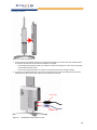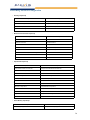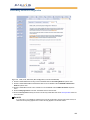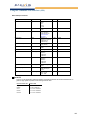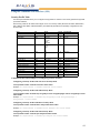
1
ORiNOCO AP-600 Access Point
User Guide
Copyright
© 2003-2004 Proxim Corporation. All rights reserved. Covered by one or more of the following U.S. patents:
5,231,634; 5,875,179; 6,006,090; 5,809,060; 6,075,812; 5,077,753. This user’s guide and the software described in it
are copyrighted with all rights reserved. No part of this publication may be reproduced, transmitted, transcribed, stored
in a retrieval system, or translated into any language in any form by any means without the written permission of
Proxim Corporation.
Trademarks
ORiNOCO is a registered trademark, and Proxim, and the Proxim logo are trademarks of Proxim Corporation. All other
trademarks mentioned herein are the property of their respective owners.
OpenSSL License Note
This product contains software developed by the OpenSSL Project for use in the OpenSSL Toolkit (http://
www.openssl.org/) and that is subject to the following copyright and conditions:
Copyright (c) 1998-2002 The OpenSSL Project. All rights reserved.
The names "OpenSSL Toolkit" and "OpenSSL Project" must not be used to refer to, endorse, or promote the products
or for any other purpose related to the products without prior written permission. For written permission, please contact
[email protected].
THIS SOFTWARE IS PROVIDED BY THE OPENSSL PROJECT “AS IS” AND ANY EXPRESSED OR IMPLIED
WARRANTIES, INCLUDING, BUT NOT LIMITED TO, THE IMPLIED WARRANTIES OF MERCHANTABILITY AND
FITNESS FOR A PARTICULAR PURPOSE ARE DISCLAIMED. IN NO EVENT SHALL THE OPENSSL PROJECT
OR ITS CONTRIBUTORS BE LIABLE FOR ANY DIRECT, INDIRECT, INCIDENTAL, SPECIAL, EXEMPLARY, OR
CONSEQUENTIAL DAMAGES (INCLUDING, BUT NOT LIMITED TO, PROCUREMENT OF SUBSTITUTE GOODS
OR SERVICES; LOSS OF USE, DATA, OR PROFITS; OR BUSINESS INTERRUPTION) HOWEVER CAUSED AND
ON ANY THEORY OF LIABILITY, WHETHER IN CONTRACT, STRICT LIABILITY, OR TORT (INCLUDING
NEGLIGENCE OR OTHERWISE) ARISING IN ANY WAY OUT OF THE USE OF THIS SOFTWARE, EVEN IF
ADVISED OF THE POSSIBILITY OF SUCH DAMAGE.
ORiNOCO AP-600 User’s Guide
Software v2.5.2
P/N 68667 R1 October 2004
2
Contents
1
Introduction . . . . . . . . . . . . . . . . . . . . . . . . . . . . . . . . . . . . . . . . . . . . . . . . . . . .12
Document Conventions . . . . . . . . . . . . . . . . . . . . . . . . . . . . . . . . . . . . . . . . . . . . . . . . . 12
Introduction to Wireless Networking . . . . . . . . . . . . . . . . . . . . . . . . . . . . . . . . . . . . . . . . 12
Guidelines for Roaming . . . . . . . . . . . . . . . . . . . . . . . . . . . . . . . . . . . . . . . . . . . . . . . . . . . . . . 13
IEEE 802.11 Specifications . . . . . . . . . . . . . . . . . . . . . . . . . . . . . . . . . . . . . . . . . . . . . . . 14
Management and Monitoring Capabilities . . . . . . . . . . . . . . . . . . . . . . . . . . . . . . . . . . . 14
HTTP/HTTPS Interface . . . . . . . . . . . . . . . . . . . . . . . . . . . . . . . . . . . . . . . . . . . . . . . . . . . . . . 14
Command Line Interface . . . . . . . . . . . . . . . . . . . . . . . . . . . . . . . . . . . . . . . . . . . . . . . . . . . . . 14
SNMP Management . . . . . . . . . . . . . . . . . . . . . . . . . . . . . . . . . . . . . . . . . . . . . . . . . . . . . . . . 15
SNMPv3 Secure Management . . . . . . . . . . . . . . . . . . . . . . . . . . . . . . . . . . . . . . . . . . . . . . 15
2
Getting Started . . . . . . . . . . . . . . . . . . . . . . . . . . . . . . . . . . . . . . . . . . . . . . . . . .16
Prerequisites . . . . . . . . . . . . . . . . . . . . . . . . . . . . . . . . . . . . . . . . . . . . . . . . . . . . . . . . . . 16
Product Package . . . . . . . . . . . . . . . . . . . . . . . . . . . . . . . . . . . . . . . . . . . . . . . . . . . . . . 17
5 GHz Antenna Adapter or AP-2000 11a Upgrade Kit. . . . . . . . . . . . . . . . . . . . . . . . . . . . . . . 17
System Requirements . . . . . . . . . . . . . . . . . . . . . . . . . . . . . . . . . . . . . . . . . . . . . . . . . . 17
Hardware Installation . . . . . . . . . . . . . . . . . . . . . . . . . . . . . . . . . . . . . . . . . . . . . . . . . . . 18
AP-2000 with Active Ethernet . . . . . . . . . . . . . . . . . . . . . . . . . . . . . . . . . . . . . . . . . . . . . . . . . 18
AP-2000 with Power Supply . . . . . . . . . . . . . . . . . . . . . . . . . . . . . . . . . . . . . . . . . . . . . . . . . . 19
5 GHz or AP-2000 11a Upgrade Kit. . . . . . . . . . . . . . . . . . . . . . . . . . . . . . . . . . . . . . . . . . . . . 22
Initialization . . . . . . . . . . . . . . . . . . . . . . . . . . . . . . . . . . . . . . . . . . . . . . . . . . . . . . . . . . . 24
ScanTool . . . . . . . . . . . . . . . . . . . . . . . . . . . . . . . . . . . . . . . . . . . . . . . . . . . . . . . . . . . . . . . . . 24
ScanTool Instructions . . . . . . . . . . . . . . . . . . . . . . . . . . . . . . . . . . . . . . . . . . . . . . . . . . . . . 24
Setup Wizard . . . . . . . . . . . . . . . . . . . . . . . . . . . . . . . . . . . . . . . . . . . . . . . . . . . . . . . . . . . . . . 26
Setup Wizard Instructions. . . . . . . . . . . . . . . . . . . . . . . . . . . . . . . . . . . . . . . . . . . . . . . . . . 26
Download the Latest Software . . . . . . . . . . . . . . . . . . . . . . . . . . . . . . . . . . . . . . . . . . . . 29
Setup your TFTP Server . . . . . . . . . . . . . . . . . . . . . . . . . . . . . . . . . . . . . . . . . . . . . . . . . . . . . 30
Download Updates from your TFTP Server using the Web Interface . . . . . . . . . . . . . . . . . . . 30
Download Updates from your TFTP Server using the CLI Interface . . . . . . . . . . . . . . . . . . . . 31
Additional Hardware Features . . . . . . . . . . . . . . . . . . . . . . . . . . . . . . . . . . . . . . . . . . . . 31
Installing the AP in a Plenum. . . . . . . . . . . . . . . . . . . . . . . . . . . . . . . . . . . . . . . . . . . . . . . . . . 31
Installing/Removing the Metal Faceplate . . . . . . . . . . . . . . . . . . . . . . . . . . . . . . . . . . . . . . 31
Active Ethernet . . . . . . . . . . . . . . . . . . . . . . . . . . . . . . . . . . . . . . . . . . . . . . . . . . . . . . . . . . . . 32
3
Contents
LED Indicators . . . . . . . . . . . . . . . . . . . . . . . . . . . . . . . . . . . . . . . . . . . . . . . . . . . . . . . . . . . . . 32
3
Viewing Status Information . . . . . . . . . . . . . . . . . . . . . . . . . . . . . . . . . . . . . . . .34
Logging into the HTTP Interface . . . . . . . . . . . . . . . . . . . . . . . . . . . . . . . . . . . . . . . . . . . 34
System Status . . . . . . . . . . . . . . . . . . . . . . . . . . . . . . . . . . . . . . . . . . . . . . . . . . . . . . . . . 35
4
Performing Advanced Configuration . . . . . . . . . . . . . . . . . . . . . . . . . . . . . . . .36
Configuring the AP Using the HTTP/HTTPS Interface . . . . . . . . . . . . . . . . . . . . . . . . . . 36
System . . . . . . . . . . . . . . . . . . . . . . . . . . . . . . . . . . . . . . . . . . . . . . . . . . . . . . . . . . . . . . 38
Dynamic DNS Support. . . . . . . . . . . . . . . . . . . . . . . . . . . . . . . . . . . . . . . . . . . . . . . . . . . . . . . 38
Access Point System Naming Convention . . . . . . . . . . . . . . . . . . . . . . . . . . . . . . . . . . . . . 38
Network . . . . . . . . . . . . . . . . . . . . . . . . . . . . . . . . . . . . . . . . . . . . . . . . . . . . . . . . . . . . . . 39
IP Configuration . . . . . . . . . . . . . . . . . . . . . . . . . . . . . . . . . . . . . . . . . . . . . . . . . . . . . . . . . . . . 39
DHCP Server . . . . . . . . . . . . . . . . . . . . . . . . . . . . . . . . . . . . . . . . . . . . . . . . . . . . . . . . . . . . . . 40
Link Integrity . . . . . . . . . . . . . . . . . . . . . . . . . . . . . . . . . . . . . . . . . . . . . . . . . . . . . . . . . . . . . . 41
Interfaces . . . . . . . . . . . . . . . . . . . . . . . . . . . . . . . . . . . . . . . . . . . . . . . . . . . . . . . . . . . . 42
Operational Mode . . . . . . . . . . . . . . . . . . . . . . . . . . . . . . . . . . . . . . . . . . . . . . . . . . . . . . . . . . 43
Operational Mode Selection . . . . . . . . . . . . . . . . . . . . . . . . . . . . . . . . . . . . . . . . . . . . . . . . 43
8Wireless-A and Wireless-B . . . . . . . . . . . . . . . . . . . . . . . . . . . . . . . . . . . . . . . . . . . . . . . . . . 43
Wireless A (802.11a) . . . . . . . . . . . . . . . . . . . . . . . . . . . . . . . . . . . . . . . . . . . . . . . . . . . . . 43
Wireless (802.11b) . . . . . . . . . . . . . . . . . . . . . . . . . . . . . . . . . . . . . . . . . . . . . . . . . . . . . . . 45
Wireless (802.11b/g). . . . . . . . . . . . . . . . . . . . . . . . . . . . . . . . . . . . . . . . . . . . . . . . . . . . . . 48
Wireless Distribution System (WDS) . . . . . . . . . . . . . . . . . . . . . . . . . . . . . . . . . . . . . . . . . 49
Ethernet . . . . . . . . . . . . . . . . . . . . . . . . . . . . . . . . . . . . . . . . . . . . . . . . . . . . . . . . . . . . . . . . . . 52
Management . . . . . . . . . . . . . . . . . . . . . . . . . . . . . . . . . . . . . . . . . . . . . . . . . . . . . . . . . . 53
Passwords . . . . . . . . . . . . . . . . . . . . . . . . . . . . . . . . . . . . . . . . . . . . . . . . . . . . . . . . . . . . . . . . 53
IP Access Table . . . . . . . . . . . . . . . . . . . . . . . . . . . . . . . . . . . . . . . . . . . . . . . . . . . . . . . . . . . . 53
Services . . . . . . . . . . . . . . . . . . . . . . . . . . . . . . . . . . . . . . . . . . . . . . . . . . . . . . . . . . . . . . . . . . 54
Secure Management . . . . . . . . . . . . . . . . . . . . . . . . . . . . . . . . . . . . . . . . . . . . . . . . . . . . . 54
SNMP Settings . . . . . . . . . . . . . . . . . . . . . . . . . . . . . . . . . . . . . . . . . . . . . . . . . . . . . . . . . . 54
HTTP Access . . . . . . . . . . . . . . . . . . . . . . . . . . . . . . . . . . . . . . . . . . . . . . . . . . . . . . . . . . . 54
HTTPS Access . . . . . . . . . . . . . . . . . . . . . . . . . . . . . . . . . . . . . . . . . . . . . . . . . . . . . . . . . . 54
Telnet Configuration Settings . . . . . . . . . . . . . . . . . . . . . . . . . . . . . . . . . . . . . . . . . . . . . . . 56
Secure Shell (SSH) Settings . . . . . . . . . . . . . . . . . . . . . . . . . . . . . . . . . . . . . . . . . . . . . . . 56
Serial Configuration Settings . . . . . . . . . . . . . . . . . . . . . . . . . . . . . . . . . . . . . . . . . . . . . . . 58
RADIUS Based Management Access . . . . . . . . . . . . . . . . . . . . . . . . . . . . . . . . . . . . . . . . 58
Automatic Configuration (AutoConfig) . . . . . . . . . . . . . . . . . . . . . . . . . . . . . . . . . . . . . . . . . . . 59
Auto Configuration and the CLI Batch File . . . . . . . . . . . . . . . . . . . . . . . . . . . . . . . . . . . . . 59
Hardware Configuration Reset (CHRP). . . . . . . . . . . . . . . . . . . . . . . . . . . . . . . . . . . . . . . . . . 62
Configuration Reset via Serial Port During Bootup . . . . . . . . . . . . . . . . . . . . . . . . . . . . . . 62
Configuring Hardware Configuration Reset . . . . . . . . . . . . . . . . . . . . . . . . . . . . . . . . . . . . 63
4
Contents
Procedure to Reset Configuration via the Serial Interface . . . . . . . . . . . . . . . . . . . . . . . . . 63
Filtering . . . . . . . . . . . . . . . . . . . . . . . . . . . . . . . . . . . . . . . . . . . . . . . . . . . . . . . . . . . . . . 64
Ethernet Protocol . . . . . . . . . . . . . . . . . . . . . . . . . . . . . . . . . . . . . . . . . . . . . . . . . . . . . . . . . . . 64
Static MAC . . . . . . . . . . . . . . . . . . . . . . . . . . . . . . . . . . . . . . . . . . . . . . . . . . . . . . . . . . . . . . . . 64
Static MAC Filter Examples . . . . . . . . . . . . . . . . . . . . . . . . . . . . . . . . . . . . . . . . . . . . . . . . 66
Advanced. . . . . . . . . . . . . . . . . . . . . . . . . . . . . . . . . . . . . . . . . . . . . . . . . . . . . . . . . . . . . . . . . 67
TCP/UDP Port . . . . . . . . . . . . . . . . . . . . . . . . . . . . . . . . . . . . . . . . . . . . . . . . . . . . . . . . . . . . . 67
Adding TCP/UDP Port Filters . . . . . . . . . . . . . . . . . . . . . . . . . . . . . . . . . . . . . . . . . . . . . . . 67
Editing TCP/UDP Port Filters . . . . . . . . . . . . . . . . . . . . . . . . . . . . . . . . . . . . . . . . . . . . . . . 68
Alarms . . . . . . . . . . . . . . . . . . . . . . . . . . . . . . . . . . . . . . . . . . . . . . . . . . . . . . . . . . . . . . . 69
Groups . . . . . . . . . . . . . . . . . . . . . . . . . . . . . . . . . . . . . . . . . . . . . . . . . . . . . . . . . . . . . . . . . . . 69
Severity Levels . . . . . . . . . . . . . . . . . . . . . . . . . . . . . . . . . . . . . . . . . . . . . . . . . . . . . . . . . . 72
Alarm Host Table . . . . . . . . . . . . . . . . . . . . . . . . . . . . . . . . . . . . . . . . . . . . . . . . . . . . . . . . . . . 72
Syslog . . . . . . . . . . . . . . . . . . . . . . . . . . . . . . . . . . . . . . . . . . . . . . . . . . . . . . . . . . . . . . . . . . . 72
Setting Syslog Event Notifications . . . . . . . . . . . . . . . . . . . . . . . . . . . . . . . . . . . . . . . . . . . 72
Configuring Syslog Event Notifications. . . . . . . . . . . . . . . . . . . . . . . . . . . . . . . . . . . . . . . . 72
Syslog Messages . . . . . . . . . . . . . . . . . . . . . . . . . . . . . . . . . . . . . . . . . . . . . . . . . . . . . . . . 73
Rogue Access Point Detection (RAD) . . . . . . . . . . . . . . . . . . . . . . . . . . . . . . . . . . . . . . . . . . . 74
RAD Configuration Requirements . . . . . . . . . . . . . . . . . . . . . . . . . . . . . . . . . . . . . . . . . . . 74
Configuring RAD. . . . . . . . . . . . . . . . . . . . . . . . . . . . . . . . . . . . . . . . . . . . . . . . . . . . . . . . . 75
Bridge . . . . . . . . . . . . . . . . . . . . . . . . . . . . . . . . . . . . . . . . . . . . . . . . . . . . . . . . . . . . . . . 76
Spanning Tree . . . . . . . . . . . . . . . . . . . . . . . . . . . . . . . . . . . . . . . . . . . . . . . . . . . . . . . . . . . . . 76
Storm Threshold . . . . . . . . . . . . . . . . . . . . . . . . . . . . . . . . . . . . . . . . . . . . . . . . . . . . . . . . . . . 76
Intra BSS . . . . . . . . . . . . . . . . . . . . . . . . . . . . . . . . . . . . . . . . . . . . . . . . . . . . . . . . . . . . . . . . . 76
Packet Forwarding (Pkt Fwd) . . . . . . . . . . . . . . . . . . . . . . . . . . . . . . . . . . . . . . . . . . . . . . . . . 77
QoS (Quality of Service) . . . . . . . . . . . . . . . . . . . . . . . . . . . . . . . . . . . . . . . . . . . . . . . . . 77
RADIUS Profiles . . . . . . . . . . . . . . . . . . . . . . . . . . . . . . . . . . . . . . . . . . . . . . . . . . . . . . . 78
RADIUS Servers per Authentication Mode and per VLAN . . . . . . . . . . . . . . . . . . . . . . . . . . . 78
RADIUS-based VLAN Assignment . . . . . . . . . . . . . . . . . . . . . . . . . . . . . . . . . . . . . . . . . . . 79
RADIUS Servers Enforcing VLAN Access Control . . . . . . . . . . . . . . . . . . . . . . . . . . . . . . . 79
Configuring RADIUS Profiles. . . . . . . . . . . . . . . . . . . . . . . . . . . . . . . . . . . . . . . . . . . . . . . . . . 79
Adding or Modifying a RADIUS Server Profile . . . . . . . . . . . . . . . . . . . . . . . . . . . . . . . . . . 80
MAC Access Control Via RADIUS Authentication . . . . . . . . . . . . . . . . . . . . . . . . . . . . . . . . . . 81
802.1x Authentication using RADIUS . . . . . . . . . . . . . . . . . . . . . . . . . . . . . . . . . . . . . . . . . . . 81
RADIUS Accounting . . . . . . . . . . . . . . . . . . . . . . . . . . . . . . . . . . . . . . . . . . . . . . . . . . . . . . . . 82
Session Length . . . . . . . . . . . . . . . . . . . . . . . . . . . . . . . . . . . . . . . . . . . . . . . . . . . . . . . . . . 82
SSID/VLAN/Security . . . . . . . . . . . . . . . . . . . . . . . . . . . . . . . . . . . . . . . . . . . . . . . . . . . . 83
Management VLAN . . . . . . . . . . . . . . . . . . . . . . . . . . . . . . . . . . . . . . . . . . . . . . . . . . . . . . . . . 83
VLAN Overview . . . . . . . . . . . . . . . . . . . . . . . . . . . . . . . . . . . . . . . . . . . . . . . . . . . . . . . . . 83
Enabling/Disabling VLAN Protocol . . . . . . . . . . . . . . . . . . . . . . . . . . . . . . . . . . . . . . . . . . . 85
MAC Access . . . . . . . . . . . . . . . . . . . . . . . . . . . . . . . . . . . . . . . . . . . . . . . . . . . . . . . . . . . . . . 86
5
Contents
Configuring MAC Access . . . . . . . . . . . . . . . . . . . . . . . . . . . . . . . . . . . . . . . . . . . . . . . . . . 86
Security Profiles. . . . . . . . . . . . . . . . . . . . . . . . . . . . . . . . . . . . . . . . . . . . . . . . . . . . . . . . . . . . 87
WEP Encryption . . . . . . . . . . . . . . . . . . . . . . . . . . . . . . . . . . . . . . . . . . . . . . . . . . . . . . . . . 87
802.1x Authentication . . . . . . . . . . . . . . . . . . . . . . . . . . . . . . . . . . . . . . . . . . . . . . . . . . . . . 87
Wi-Fi Protected Access (WPA) . . . . . . . . . . . . . . . . . . . . . . . . . . . . . . . . . . . . . . . . . . . . . . 88
Authentication Protocol Hierarchy . . . . . . . . . . . . . . . . . . . . . . . . . . . . . . . . . . . . . . . . . . . 89
VLANs and Security Profiles . . . . . . . . . . . . . . . . . . . . . . . . . . . . . . . . . . . . . . . . . . . . . . . 89
Configuring Security Profiles . . . . . . . . . . . . . . . . . . . . . . . . . . . . . . . . . . . . . . . . . . . . . . . 90
Wireless-A and Wireless-B . . . . . . . . . . . . . . . . . . . . . . . . . . . . . . . . . . . . . . . . . . . . . . . . . . . 93
Adding or Modifying an SSID/VLAN with VLAN Protocol Disabled . . . . . . . . . . . . . . . . . . 93
Adding or Modifying an SSID/VLAN with VLAN Protocol Enabled . . . . . . . . . . . . . . . . . . . 96
Broadcast SSID and Closed System . . . . . . . . . . . . . . . . . . . . . . . . . . . . . . . . . . . . . . . . . 99
5
Monitoring the AP-2000 . . . . . . . . . . . . . . . . . . . . . . . . . . . . . . . . . . . . . . . . . .100
Logging into the HTTP Interface . . . . . . . . . . . . . . . . . . . . . . . . . . . . . . . . . . . . . . . . . . 100
Version . . . . . . . . . . . . . . . . . . . . . . . . . . . . . . . . . . . . . . . . . . . . . . . . . . . . . . . . . . . . . 102
ICMP . . . . . . . . . . . . . . . . . . . . . . . . . . . . . . . . . . . . . . . . . . . . . . . . . . . . . . . . . . . . . . . 103
IP/ARP Table . . . . . . . . . . . . . . . . . . . . . . . . . . . . . . . . . . . . . . . . . . . . . . . . . . . . . . . . 103
Learn Table . . . . . . . . . . . . . . . . . . . . . . . . . . . . . . . . . . . . . . . . . . . . . . . . . . . . . . . . . . 104
IAPP . . . . . . . . . . . . . . . . . . . . . . . . . . . . . . . . . . . . . . . . . . . . . . . . . . . . . . . . . . . . . . . 104
RADIUS . . . . . . . . . . . . . . . . . . . . . . . . . . . . . . . . . . . . . . . . . . . . . . . . . . . . . . . . . . . . 105
Interfaces . . . . . . . . . . . . . . . . . . . . . . . . . . . . . . . . . . . . . . . . . . . . . . . . . . . . . . . . . . . 106
Station Statistics . . . . . . . . . . . . . . . . . . . . . . . . . . . . . . . . . . . . . . . . . . . . . . . . . . . . . . 107
Enabling and Viewing Station Statistics . . . . . . . . . . . . . . . . . . . . . . . . . . . . . . . . . . . . . . . . . 107
Refreshing Station Statistics . . . . . . . . . . . . . . . . . . . . . . . . . . . . . . . . . . . . . . . . . . . . . . . . . 107
Description of Station Statistics. . . . . . . . . . . . . . . . . . . . . . . . . . . . . . . . . . . . . . . . . . . . . 107
6
Performing Commands . . . . . . . . . . . . . . . . . . . . . . . . . . . . . . . . . . . . . . . . . .109
Logging into the HTTP Interface . . . . . . . . . . . . . . . . . . . . . . . . . . . . . . . . . . . . . . . . . . 109
Introduction to File Transfer via TFTP or HTTP . . . . . . . . . . . . . . . . . . . . . . . . . . . . . . 111
TFTP File Transfer Guidelines. . . . . . . . . . . . . . . . . . . . . . . . . . . . . . . . . . . . . . . . . . . . . . . . .111
HTTP File Transfer Guidelines . . . . . . . . . . . . . . . . . . . . . . . . . . . . . . . . . . . . . . . . . . . . . . . .111
Image Error Checking during File Transfer . . . . . . . . . . . . . . . . . . . . . . . . . . . . . . . . . . . . . . .111
Update AP via TFTP . . . . . . . . . . . . . . . . . . . . . . . . . . . . . . . . . . . . . . . . . . . . . . . . . . . 112
Update AP via HTTP . . . . . . . . . . . . . . . . . . . . . . . . . . . . . . . . . . . . . . . . . . . . . . . . . . 113
Retrieve File via TFTP . . . . . . . . . . . . . . . . . . . . . . . . . . . . . . . . . . . . . . . . . . . . . . . . . 115
Retrieve File via HTTP . . . . . . . . . . . . . . . . . . . . . . . . . . . . . . . . . . . . . . . . . . . . . . . . . 116
Reboot . . . . . . . . . . . . . . . . . . . . . . . . . . . . . . . . . . . . . . . . . . . . . . . . . . . . . . . . . . . . . 118
Reset . . . . . . . . . . . . . . . . . . . . . . . . . . . . . . . . . . . . . . . . . . . . . . . . . . . . . . . . . . . . . . 119
6
Contents
Help Link . . . . . . . . . . . . . . . . . . . . . . . . . . . . . . . . . . . . . . . . . . . . . . . . . . . . . . . . . . . . 120
7
Troubleshooting the AP-2000 . . . . . . . . . . . . . . . . . . . . . . . . . . . . . . . . . . . . .121
Troubleshooting Concepts . . . . . . . . . . . . . . . . . . . . . . . . . . . . . . . . . . . . . . . . . . . . . . 121
Symptoms and Solutions . . . . . . . . . . . . . . . . . . . . . . . . . . . . . . . . . . . . . . . . . . . . . . . 122
Connectivity Issues . . . . . . . . . . . . . . . . . . . . . . . . . . . . . . . . . . . . . . . . . . . . . . . . . . . . . . . . 122
AP Unit Will Not Boot - No LED Activity . . . . . . . . . . . . . . . . . . . . . . . . . . . . . . . . . . . . . . 122
Serial Link Does Not Work . . . . . . . . . . . . . . . . . . . . . . . . . . . . . . . . . . . . . . . . . . . . . . . . 122
Ethernet Link Does Not Work . . . . . . . . . . . . . . . . . . . . . . . . . . . . . . . . . . . . . . . . . . . . . . 122
Basic Software Setup and Configuration Problems. . . . . . . . . . . . . . . . . . . . . . . . . . . . . . . . 122
Lost AP, Telnet, or SNMP Password. . . . . . . . . . . . . . . . . . . . . . . . . . . . . . . . . . . . . . . . . 122
Client Computer Cannot Connect. . . . . . . . . . . . . . . . . . . . . . . . . . . . . . . . . . . . . . . . . . . 122
AP Has Incorrect IP Address . . . . . . . . . . . . . . . . . . . . . . . . . . . . . . . . . . . . . . . . . . . . . . 122
HTTP (browser) or Telnet Interface Does Not Work . . . . . . . . . . . . . . . . . . . . . . . . . . . . . 123
HTML Help Files Do Not Appear . . . . . . . . . . . . . . . . . . . . . . . . . . . . . . . . . . . . . . . . . . . 123
Telnet CLI Does Not Work . . . . . . . . . . . . . . . . . . . . . . . . . . . . . . . . . . . . . . . . . . . . . . . . 123
TFTP Server Does Not Work . . . . . . . . . . . . . . . . . . . . . . . . . . . . . . . . . . . . . . . . . . . . . . 123
Client Connection Problems . . . . . . . . . . . . . . . . . . . . . . . . . . . . . . . . . . . . . . . . . . . . . . . . . 124
Client Software Finds No Connection. . . . . . . . . . . . . . . . . . . . . . . . . . . . . . . . . . . . . . . . 124
Client PC Card Does Not Work . . . . . . . . . . . . . . . . . . . . . . . . . . . . . . . . . . . . . . . . . . . . 124
Intermittent Loss of Connection . . . . . . . . . . . . . . . . . . . . . . . . . . . . . . . . . . . . . . . . . . . . 124
Client Does Not Receive an IP Address - Cannot Connect to Internet . . . . . . . . . . . . . . 124
VLAN Operation Issues . . . . . . . . . . . . . . . . . . . . . . . . . . . . . . . . . . . . . . . . . . . . . . . . . . . . . 124
Verifying Proper Operation of the VLAN Feature . . . . . . . . . . . . . . . . . . . . . . . . . . . . . . . 124
VLAN Workgroups . . . . . . . . . . . . . . . . . . . . . . . . . . . . . . . . . . . . . . . . . . . . . . . . . . . . . . 124
Active Ethernet (AE) . . . . . . . . . . . . . . . . . . . . . . . . . . . . . . . . . . . . . . . . . . . . . . . . . . . . . . . 125
The AP Does Not Work . . . . . . . . . . . . . . . . . . . . . . . . . . . . . . . . . . . . . . . . . . . . . . . . . . 125
There Is No Data Link. . . . . . . . . . . . . . . . . . . . . . . . . . . . . . . . . . . . . . . . . . . . . . . . . . . . 125
“Overload” Indications . . . . . . . . . . . . . . . . . . . . . . . . . . . . . . . . . . . . . . . . . . . . . . . . . . . 125
Recovery Procedures . . . . . . . . . . . . . . . . . . . . . . . . . . . . . . . . . . . . . . . . . . . . . . . . . . 125
Reset to Factory Default Procedure . . . . . . . . . . . . . . . . . . . . . . . . . . . . . . . . . . . . . . . . . . . 126
Forced Reload Procedure . . . . . . . . . . . . . . . . . . . . . . . . . . . . . . . . . . . . . . . . . . . . . . . . . . . 126
Download a New Image Using ScanTool . . . . . . . . . . . . . . . . . . . . . . . . . . . . . . . . . . . . . 127
Download a New Image Using the Bootloader CLI . . . . . . . . . . . . . . . . . . . . . . . . . . . . . 128
Setting IP Address using Serial Port . . . . . . . . . . . . . . . . . . . . . . . . . . . . . . . . . . . . . . . . . . . 129
Hardware and Software Requirements. . . . . . . . . . . . . . . . . . . . . . . . . . . . . . . . . . . . . . . 129
Attaching the Serial Port Cable. . . . . . . . . . . . . . . . . . . . . . . . . . . . . . . . . . . . . . . . . . . . . 129
Initializing the IP Address using CLI . . . . . . . . . . . . . . . . . . . . . . . . . . . . . . . . . . . . . . . . . 129
Related Applications . . . . . . . . . . . . . . . . . . . . . . . . . . . . . . . . . . . . . . . . . . . . . . . . . . . 131
RADIUS Authentication Server . . . . . . . . . . . . . . . . . . . . . . . . . . . . . . . . . . . . . . . . . . . . . . . 131
TFTP Server . . . . . . . . . . . . . . . . . . . . . . . . . . . . . . . . . . . . . . . . . . . . . . . . . . . . . . . . . . . . . 131
7
Contents
A Using the Command Line Interface (CLI). . . . . . . . . . . . . . . . . . . . . . . . . . . .132
General Notes . . . . . . . . . . . . . . . . . . . . . . . . . . . . . . . . . . . . . . . . . . . . . . . . . . . . . . . . 132
Prerequisite Skills and Knowledge . . . . . . . . . . . . . . . . . . . . . . . . . . . . . . . . . . . . . . . . . . . . 132
Notation Conventions . . . . . . . . . . . . . . . . . . . . . . . . . . . . . . . . . . . . . . . . . . . . . . . . . . . . . . 132
Important Terminology . . . . . . . . . . . . . . . . . . . . . . . . . . . . . . . . . . . . . . . . . . . . . . . . . . . . . . 132
Navigation and Special Keys . . . . . . . . . . . . . . . . . . . . . . . . . . . . . . . . . . . . . . . . . . . . . . . . . 133
CLI Error Messages. . . . . . . . . . . . . . . . . . . . . . . . . . . . . . . . . . . . . . . . . . . . . . . . . . . . . . . . 133
Command Line Interface (CLI) Variations . . . . . . . . . . . . . . . . . . . . . . . . . . . . . . . . . . . 133
Bootloader CLI. . . . . . . . . . . . . . . . . . . . . . . . . . . . . . . . . . . . . . . . . . . . . . . . . . . . . . . . . . . . 134
CLI Command Types . . . . . . . . . . . . . . . . . . . . . . . . . . . . . . . . . . . . . . . . . . . . . . . . . . 135
Operational CLI Commands . . . . . . . . . . . . . . . . . . . . . . . . . . . . . . . . . . . . . . . . . . . . . . . . . 135
? (List Commands) . . . . . . . . . . . . . . . . . . . . . . . . . . . . . . . . . . . . . . . . . . . . . . . . . . . . . . 135
done, exit, quit . . . . . . . . . . . . . . . . . . . . . . . . . . . . . . . . . . . . . . . . . . . . . . . . . . . . . . . . . 137
download . . . . . . . . . . . . . . . . . . . . . . . . . . . . . . . . . . . . . . . . . . . . . . . . . . . . . . . . . . . . . 137
help . . . . . . . . . . . . . . . . . . . . . . . . . . . . . . . . . . . . . . . . . . . . . . . . . . . . . . . . . . . . . . . . . . 137
history . . . . . . . . . . . . . . . . . . . . . . . . . . . . . . . . . . . . . . . . . . . . . . . . . . . . . . . . . . . . . . . . 138
passwd . . . . . . . . . . . . . . . . . . . . . . . . . . . . . . . . . . . . . . . . . . . . . . . . . . . . . . . . . . . . . . . 138
reboot . . . . . . . . . . . . . . . . . . . . . . . . . . . . . . . . . . . . . . . . . . . . . . . . . . . . . . . . . . . . . . . . 138
search . . . . . . . . . . . . . . . . . . . . . . . . . . . . . . . . . . . . . . . . . . . . . . . . . . . . . . . . . . . . . . . . 138
upload. . . . . . . . . . . . . . . . . . . . . . . . . . . . . . . . . . . . . . . . . . . . . . . . . . . . . . . . . . . . . . . . 139
Parameter Control Commands . . . . . . . . . . . . . . . . . . . . . . . . . . . . . . . . . . . . . . . . . . . . . . . 139
“show” CLI Command. . . . . . . . . . . . . . . . . . . . . . . . . . . . . . . . . . . . . . . . . . . . . . . . . . . . 139
“set” CLI Command . . . . . . . . . . . . . . . . . . . . . . . . . . . . . . . . . . . . . . . . . . . . . . . . . . . . . 139
Configuring Objects that Require Reboot . . . . . . . . . . . . . . . . . . . . . . . . . . . . . . . . . . . . . 140
“set” and “show” Command Examples . . . . . . . . . . . . . . . . . . . . . . . . . . . . . . . . . . . . . . . 140
Using Tables & User Strings . . . . . . . . . . . . . . . . . . . . . . . . . . . . . . . . . . . . . . . . . . . . . 142
Working with Tables. . . . . . . . . . . . . . . . . . . . . . . . . . . . . . . . . . . . . . . . . . . . . . . . . . . . . . . . 142
Using Strings . . . . . . . . . . . . . . . . . . . . . . . . . . . . . . . . . . . . . . . . . . . . . . . . . . . . . . . . . . . . . 143
Configuring the AP using CLI commands . . . . . . . . . . . . . . . . . . . . . . . . . . . . . . . . . . . 143
Log into the AP using HyperTerminal . . . . . . . . . . . . . . . . . . . . . . . . . . . . . . . . . . . . . . . . . . 143
Log into the AP using Telnet . . . . . . . . . . . . . . . . . . . . . . . . . . . . . . . . . . . . . . . . . . . . . . . . . 143
Set Basic Configuration Parameters using CLI Commands . . . . . . . . . . . . . . . . . . . . . 144
Set System Name, Location and Contact Information . . . . . . . . . . . . . . . . . . . . . . . . . . . 144
Set Static IP Address for the AP . . . . . . . . . . . . . . . . . . . . . . . . . . . . . . . . . . . . . . . . . . . . 144
Change Passwords . . . . . . . . . . . . . . . . . . . . . . . . . . . . . . . . . . . . . . . . . . . . . . . . . . . . . 144
Set Network Names for the Wireless Interface. . . . . . . . . . . . . . . . . . . . . . . . . . . . . . . . . 145
Enable and Configure TX Power Control for the Wireless Interface(s) . . . . . . . . . . . . . . 145
Configure SSID (Network Name) and VLAN Pairs, and Profiles . . . . . . . . . . . . . . . . . . . 145
Download an AP Configuration File from your TFTP Server . . . . . . . . . . . . . . . . . . . . . . 147
Backup your AP Configuration File. . . . . . . . . . . . . . . . . . . . . . . . . . . . . . . . . . . . . . . . . . 147
8
Contents
Set up Auto Configuration . . . . . . . . . . . . . . . . . . . . . . . . . . . . . . . . . . . . . . . . . . . . . . . . 147
Other Network Settings . . . . . . . . . . . . . . . . . . . . . . . . . . . . . . . . . . . . . . . . . . . . . . . . . 147
Configure the AP as a DHCP Server . . . . . . . . . . . . . . . . . . . . . . . . . . . . . . . . . . . . . . . . 148
Configure the DNS Client . . . . . . . . . . . . . . . . . . . . . . . . . . . . . . . . . . . . . . . . . . . . . . . . . 148
Maintain Client Connections using Link Integrity . . . . . . . . . . . . . . . . . . . . . . . . . . . . . . . 148
Change your Wireless Interface Settings . . . . . . . . . . . . . . . . . . . . . . . . . . . . . . . . . . . . . 148
Set Ethernet Speed and Transmission Mode . . . . . . . . . . . . . . . . . . . . . . . . . . . . . . . . . . 150
Set Interface Management Services . . . . . . . . . . . . . . . . . . . . . . . . . . . . . . . . . . . . . . . . 150
Configure Syslog . . . . . . . . . . . . . . . . . . . . . . . . . . . . . . . . . . . . . . . . . . . . . . . . . . . . . . . 151
Configure Intra BSS . . . . . . . . . . . . . . . . . . . . . . . . . . . . . . . . . . . . . . . . . . . . . . . . . . . . . 151
Configure MAC Access Control . . . . . . . . . . . . . . . . . . . . . . . . . . . . . . . . . . . . . . . . . . . . 152
Set RADIUS Parameters . . . . . . . . . . . . . . . . . . . . . . . . . . . . . . . . . . . . . . . . . . . . . . . . . 153
Set Rogue Access Point Detection (RAD) Parameters . . . . . . . . . . . . . . . . . . . . . . . . . . 155
Set Hardware Configuration Reset Parameters . . . . . . . . . . . . . . . . . . . . . . . . . . . . . . . . 156
Set VLAN/SSID Parameters . . . . . . . . . . . . . . . . . . . . . . . . . . . . . . . . . . . . . . . . . . . . . . . 156
CLI Monitoring Parameters . . . . . . . . . . . . . . . . . . . . . . . . . . . . . . . . . . . . . . . . . . . . . . 156
Parameter Tables . . . . . . . . . . . . . . . . . . . . . . . . . . . . . . . . . . . . . . . . . . . . . . . . . . . . . 156
System Parameters . . . . . . . . . . . . . . . . . . . . . . . . . . . . . . . . . . . . . . . . . . . . . . . . . . . . . . . . 158
Inventory Management Information . . . . . . . . . . . . . . . . . . . . . . . . . . . . . . . . . . . . . . . . . 159
Network Parameters . . . . . . . . . . . . . . . . . . . . . . . . . . . . . . . . . . . . . . . . . . . . . . . . . . . . . . . 159
IP Configuration Parameters . . . . . . . . . . . . . . . . . . . . . . . . . . . . . . . . . . . . . . . . . . . . . . 159
DHCP Server Parameters . . . . . . . . . . . . . . . . . . . . . . . . . . . . . . . . . . . . . . . . . . . . . . . . 160
Link Integrity Parameters . . . . . . . . . . . . . . . . . . . . . . . . . . . . . . . . . . . . . . . . . . . . . . . . . 161
Interface Parameters . . . . . . . . . . . . . . . . . . . . . . . . . . . . . . . . . . . . . . . . . . . . . . . . . . . . . . . 162
Wireless Interface Parameters . . . . . . . . . . . . . . . . . . . . . . . . . . . . . . . . . . . . . . . . . . . . . 162
Wireless Interface SSID/VLAN/Profile Parameters . . . . . . . . . . . . . . . . . . . . . . . . . . . . . 165
Ethernet Interface Parameters . . . . . . . . . . . . . . . . . . . . . . . . . . . . . . . . . . . . . . . . . . . . . 166
Management Parameters . . . . . . . . . . . . . . . . . . . . . . . . . . . . . . . . . . . . . . . . . . . . . . . . . . . 166
Secure Management Parameters. . . . . . . . . . . . . . . . . . . . . . . . . . . . . . . . . . . . . . . . . . . 166
SNMP Parameters . . . . . . . . . . . . . . . . . . . . . . . . . . . . . . . . . . . . . . . . . . . . . . . . . . . . . . 166
HTTP (web browser) Parameters . . . . . . . . . . . . . . . . . . . . . . . . . . . . . . . . . . . . . . . . . . . 166
Telnet Parameters . . . . . . . . . . . . . . . . . . . . . . . . . . . . . . . . . . . . . . . . . . . . . . . . . . . . . . 167
Serial Port Parameters . . . . . . . . . . . . . . . . . . . . . . . . . . . . . . . . . . . . . . . . . . . . . . . . . . . 167
RADIUS Based Management Access Parameters. . . . . . . . . . . . . . . . . . . . . . . . . . . . . . 168
SSH Parameters. . . . . . . . . . . . . . . . . . . . . . . . . . . . . . . . . . . . . . . . . . . . . . . . . . . . . . . . 168
Auto Configuration Parameters . . . . . . . . . . . . . . . . . . . . . . . . . . . . . . . . . . . . . . . . . . . . 169
TFTP Server Parameters . . . . . . . . . . . . . . . . . . . . . . . . . . . . . . . . . . . . . . . . . . . . . . . . . 169
IP Access Table Parameters . . . . . . . . . . . . . . . . . . . . . . . . . . . . . . . . . . . . . . . . . . . . . . 169
Filtering Parameters . . . . . . . . . . . . . . . . . . . . . . . . . . . . . . . . . . . . . . . . . . . . . . . . . . . . . . . 170
Ethernet Protocol Filtering Parameters . . . . . . . . . . . . . . . . . . . . . . . . . . . . . . . . . . . . . . 170
Static MAC Address Filter Table . . . . . . . . . . . . . . . . . . . . . . . . . . . . . . . . . . . . . . . . . . . . 170
9
Contents
Proxy ARP Parameters . . . . . . . . . . . . . . . . . . . . . . . . . . . . . . . . . . . . . . . . . . . . . . . . . . 171
IP ARP Filtering Parameters . . . . . . . . . . . . . . . . . . . . . . . . . . . . . . . . . . . . . . . . . . . . . . 171
Broadcast Filtering Table . . . . . . . . . . . . . . . . . . . . . . . . . . . . . . . . . . . . . . . . . . . . . . . . . 171
TCP/UDP Port Filtering . . . . . . . . . . . . . . . . . . . . . . . . . . . . . . . . . . . . . . . . . . . . . . . . . . 171
Alarms Parameters . . . . . . . . . . . . . . . . . . . . . . . . . . . . . . . . . . . . . . . . . . . . . . . . . . . . . . . . 172
SNMP Table Host Table Parameters . . . . . . . . . . . . . . . . . . . . . . . . . . . . . . . . . . . . . . . . 172
Syslog Parameters . . . . . . . . . . . . . . . . . . . . . . . . . . . . . . . . . . . . . . . . . . . . . . . . . . . . . . 172
Bridge Parameters. . . . . . . . . . . . . . . . . . . . . . . . . . . . . . . . . . . . . . . . . . . . . . . . . . . . . . . . . 173
Spanning Tree Parameters. . . . . . . . . . . . . . . . . . . . . . . . . . . . . . . . . . . . . . . . . . . . . . . . 173
Storm Threshold Parameters . . . . . . . . . . . . . . . . . . . . . . . . . . . . . . . . . . . . . . . . . . . . . . 174
Intra BSS Subscriber Blocking . . . . . . . . . . . . . . . . . . . . . . . . . . . . . . . . . . . . . . . . . . . . . 174
Packet Forwarding Parameters . . . . . . . . . . . . . . . . . . . . . . . . . . . . . . . . . . . . . . . . . . . . 174
Security Parameters . . . . . . . . . . . . . . . . . . . . . . . . . . . . . . . . . . . . . . . . . . . . . . . . . . . . . . . 175
MAC Access Control Parameter. . . . . . . . . . . . . . . . . . . . . . . . . . . . . . . . . . . . . . . . . . . . 175
RADIUS Parameters . . . . . . . . . . . . . . . . . . . . . . . . . . . . . . . . . . . . . . . . . . . . . . . . . . . . . . . 175
Rogue Access Point Detection (RAD) Parameters . . . . . . . . . . . . . . . . . . . . . . . . . . . . . . . . 176
Hardware Configuration Reset . . . . . . . . . . . . . . . . . . . . . . . . . . . . . . . . . . . . . . . . . . . . . 176
VLAN/SSID Parameters . . . . . . . . . . . . . . . . . . . . . . . . . . . . . . . . . . . . . . . . . . . . . . . . . . . . 176
Security Profile Table . . . . . . . . . . . . . . . . . . . . . . . . . . . . . . . . . . . . . . . . . . . . . . . . . . . . . . . 177
Command Syntax and Examples of Configuring Security Profiles: . . . . . . . . . . . . . . . . . 177
Other Parameters . . . . . . . . . . . . . . . . . . . . . . . . . . . . . . . . . . . . . . . . . . . . . . . . . . . . . . . . . 178
IAPP Parameters . . . . . . . . . . . . . . . . . . . . . . . . . . . . . . . . . . . . . . . . . . . . . . . . . . . . . . . 178
SpectraLink VoIP Parameters (802.11b and bg Modes Only) . . . . . . . . . . . . . . . . . . . . . 178
CLI Batch File . . . . . . . . . . . . . . . . . . . . . . . . . . . . . . . . . . . . . . . . . . . . . . . . . . . . . . . . 179
Auto Configuration and the CLI Batch File . . . . . . . . . . . . . . . . . . . . . . . . . . . . . . . . . . . . . . 179
CLI Batch File Format and Syntax. . . . . . . . . . . . . . . . . . . . . . . . . . . . . . . . . . . . . . . . . . . . . 179
Sample CLI Batch File . . . . . . . . . . . . . . . . . . . . . . . . . . . . . . . . . . . . . . . . . . . . . . . . . . . 179
Reboot Behavior . . . . . . . . . . . . . . . . . . . . . . . . . . . . . . . . . . . . . . . . . . . . . . . . . . . . . . . . . . 180
CLI Batch File Error Log . . . . . . . . . . . . . . . . . . . . . . . . . . . . . . . . . . . . . . . . . . . . . . . . . . 180
B ASCII Character Chart . . . . . . . . . . . . . . . . . . . . . . . . . . . . . . . . . . . . . . . . . . .181
C Specifications . . . . . . . . . . . . . . . . . . . . . . . . . . . . . . . . . . . . . . . . . . . . . . . . . .182
Software Features . . . . . . . . . . . . . . . . . . . . . . . . . . . . . . . . . . . . . . . . . . . . . . . . . . . . 182
Management Functions . . . . . . . . . . . . . . . . . . . . . . . . . . . . . . . . . . . . . . . . . . . . . . . . . . . . . 182
Advanced Bridging Functions . . . . . . . . . . . . . . . . . . . . . . . . . . . . . . . . . . . . . . . . . . . . . . . . 183
Medium Access Control (MAC) Functions . . . . . . . . . . . . . . . . . . . . . . . . . . . . . . . . . . . . . . 183
Security Functions . . . . . . . . . . . . . . . . . . . . . . . . . . . . . . . . . . . . . . . . . . . . . . . . . . . . . . . . 183
Network Functions . . . . . . . . . . . . . . . . . . . . . . . . . . . . . . . . . . . . . . . . . . . . . . . . . . . . . . . . 184
Advanced Wireless Functions . . . . . . . . . . . . . . . . . . . . . . . . . . . . . . . . . . . . . . . . . . . . . . . 184
Hardware Specifications . . . . . . . . . . . . . . . . . . . . . . . . . . . . . . . . . . . . . . . . . . . . . . . . 184
Physical Specifications . . . . . . . . . . . . . . . . . . . . . . . . . . . . . . . . . . . . . . . . . . . . . . . . . . . . . 184
10
Electrical Specifications . . . . . . . . . . . . . . . . . . . . . . . . . . . . . . . . . . . . . . . . . . . . . . . . . . 185
Environmental Specifications . . . . . . . . . . . . . . . . . . . . . . . . . . . . . . . . . . . . . . . . . . . . . . 185
Ethernet Interface . . . . . . . . . . . . . . . . . . . . . . . . . . . . . . . . . . . . . . . . . . . . . . . . . . . . . . . . . 185
Serial Port Interface . . . . . . . . . . . . . . . . . . . . . . . . . . . . . . . . . . . . . . . . . . . . . . . . . . . . . . . . 185
Active Ethernet Interface . . . . . . . . . . . . . . . . . . . . . . . . . . . . . . . . . . . . . . . . . . . . . . . . . . . . 185
HTTP Interface . . . . . . . . . . . . . . . . . . . . . . . . . . . . . . . . . . . . . . . . . . . . . . . . . . . . . . . . . . . 185
Radio Specifications . . . . . . . . . . . . . . . . . . . . . . . . . . . . . . . . . . . . . . . . . . . . . . . . . . . 185
802.11a Channel Frequencies. . . . . . . . . . . . . . . . . . . . . . . . . . . . . . . . . . . . . . . . . . . . . . . . 186
802.11b Channel Frequencies. . . . . . . . . . . . . . . . . . . . . . . . . . . . . . . . . . . . . . . . . . . . . . . . 187
802.11g Channel Frequencies. . . . . . . . . . . . . . . . . . . . . . . . . . . . . . . . . . . . . . . . . . . . . . . . 187
Wireless Communication Range . . . . . . . . . . . . . . . . . . . . . . . . . . . . . . . . . . . . . . . . . . . . . . 188
802.11b . . . . . . . . . . . . . . . . . . . . . . . . . . . . . . . . . . . . . . . . . . . . . . . . . . . . . . . . . . . . . . 188
802.11a (5 GHz Upgrade Kit) . . . . . . . . . . . . . . . . . . . . . . . . . . . . . . . . . . . . . . . . . . . . . 189
802.11a (11a Upgrade Kit) . . . . . . . . . . . . . . . . . . . . . . . . . . . . . . . . . . . . . . . . . . . . . . . . 189
802.11b/g . . . . . . . . . . . . . . . . . . . . . . . . . . . . . . . . . . . . . . . . . . . . . . . . . . . . . . . . . . . . . 190
D Technical Support . . . . . . . . . . . . . . . . . . . . . . . . . . . . . . . . . . . . . . . . . . . . . .191
E Statement of Warranty . . . . . . . . . . . . . . . . . . . . . . . . . . . . . . . . . . . . . . . . . . .192
Warranty Coverage . . . . . . . . . . . . . . . . . . . . . . . . . . . . . . . . . . . . . . . . . . . . . . . . . . . . 192
Repair or Replacement . . . . . . . . . . . . . . . . . . . . . . . . . . . . . . . . . . . . . . . . . . . . . . . . . 192
Limitations of Warranty . . . . . . . . . . . . . . . . . . . . . . . . . . . . . . . . . . . . . . . . . . . . . . . . . . . . . 192
Support Procedures. . . . . . . . . . . . . . . . . . . . . . . . . . . . . . . . . . . . . . . . . . . . . . . . . . . . . . . . 192
Other Information . . . . . . . . . . . . . . . . . . . . . . . . . . . . . . . . . . . . . . . . . . . . . . . . . . . . . 193
Search Knowledgebase. . . . . . . . . . . . . . . . . . . . . . . . . . . . . . . . . . . . . . . . . . . . . . . . . . . . . 193
Ask a Question or Open an Issue . . . . . . . . . . . . . . . . . . . . . . . . . . . . . . . . . . . . . . . . . . . . . 193
Other Adapter Cards . . . . . . . . . . . . . . . . . . . . . . . . . . . . . . . . . . . . . . . . . . . . . . . . . . . . . . . 193
F
Regulatory Information . . . . . . . . . . . . . . . . . . . . . . . . . . . . . . . . . . . . . . . . . .194
Information to the User . . . . . . . . . . . . . . . . . . . . . . . . . . . . . . . . . . . . . . . . . . . . . . . . . 195
Wireless LAN and your Health. . . . . . . . . . . . . . . . . . . . . . . . . . . . . . . . . . . . . . . . . . . . . . . . 196
Regulatory Information . . . . . . . . . . . . . . . . . . . . . . . . . . . . . . . . . . . . . . . . . . . . . . . . . . . . . 196
United States FCC Information . . . . . . . . . . . . . . . . . . . . . . . . . . . . . . . . . . . . . . . . . . . 207
Canada IC Information . . . . . . . . . . . . . . . . . . . . . . . . . . . . . . . . . . . . . . . . . . . . . . . . . 208
Europe Information . . . . . . . . . . . . . . . . . . . . . . . . . . . . . . . . . . . . . . . . . . . . . . . . . . . . 209
Japan Information . . . . . . . . . . . . . . . . . . . . . . . . . . . . . . . . . . . . . . . . . . . . . . . . . . . . . 211
South Korea Information . . . . . . . . . . . . . . . . . . . . . . . . . . . . . . . . . . . . . . . . . . . . . . . . 212
Radio Approvals . . . . . . . . . . . . . . . . . . . . . . . . . . . . . . . . . . . . . . . . . . . . . . . . . . . . . . 213
11
Introduction
•
•
•
•
1
Document Conventions
Introduction to Wireless Networking
IEEE 802.11 Specifications
Management and Monitoring Capabilities
Document Conventions
•
•
•
•
•
•
•
•
The term, AP, refers to an Access Point.
The term, 802.11, is used to describe features that apply to the 802.11a, 802.11b, and 802.11g wireless standards.
A Single-radio AP is an Access Point that supports one IEEE radio standard. The AP-600 is a Single-radio AP.
An 802.11a AP is an Access Point that supports the IEEE 802.11a standard.
An 802.11b AP is an Access Point that supports the IEEE 802.11b standard.
An 802.11b/g AP is an Access Point that supports the IEEE 802.11g standard.
An 802.11a/g AP is an Access Point that supports the IEEE 802.11a/g standards.
Blue underlined text indicates a link to a topic or Web address. If you are viewing this documentation on your
computer, click the blue text to jump to the linked item.
NOTE
A Note indicates important information that helps you make better use of your computer.
!
CAUTION
A Caution indicates either potential damage to hardware or loss of data and tells you how to avoid the
problem.
Introduction to Wireless Networking
An AP extends the capability of an existing Ethernet network to devices on a wireless network. Wireless devices can
connect to a single Access Point, or they can move between multiple Access Points located within the same vicinity.
As wireless clients move from one coverage cell to another, they maintain network connectivity.
To determine the best location for an Access Point, Proxim recommends conducting a Site Survey before placing the
device in its final location. For information about how to conduct a Site Survey, contact your local reseller.
Before an Access Point can be configured for your specific networking requirements, it must first be initialized. See
Getting Started for details.
12
Introduction
Figure 1-1
Typical wireless network access infrastructure
Once initialized, the network administrator can configure each unit according to the network’s requirements. The AP
functions as a wireless network access point to data networks. An AP network provides:
•
•
•
•
Seamless client roaming
Easy installation and operation
Over-the-air encryption of data
High speed network links
Guidelines for Roaming
•
•
•
•
•
•
•
•
•
An AP can only communicate with client devices that support its wireless standard. For example, an 802.11a client
cannot communicate with an 802.11b AP and an 802.11b client cannot communicate with an 802.11a AP.
However, both 802.11b and 802.11g clients can communicate with an 802.11b/g AP.
All Access Points must have the same Network Name to support client roaming.
All workstations with an 802.11 client adapter installed must use either a Network Name of “any” or the same
Network Name as the Access Points that they will roam between. If an AP has Closed System enabled, a client
must have the same Network Name as the Access Point to communicate (see Interfaces).
All Access Points and clients must have the same security settings to communicate.
The Access Points’ cells must overlap to ensure that there are no gaps in coverage and to ensure that the roaming
client will always have a connection available.
The coverage area of an 802.11b or 802.11b/g AP is larger than the coverage area of an 802.11a AP. The 802.11b
and 802.11b/g APs operate in the 2.4 GHz frequency band; the 802.11a AP operates in the 5 GHz band. Products
that operate in the 2.4 GHz band offer greater range than products that operate in the 5 GHz band.
An 802.11a or 802.11b/g AP operates at faster data rates than the 802.11b AP. 802.11a and 802.11g products
operate at speeds of up to 54 Mbits/sec; 802.11b products operate at speeds of up to 11 Mbits/sec.
All Access Points in the same vicinity should use a unique, independent Channel. By default, the AP automatically
scans for available Channels during boot-up but you can also set the Channel manually (see Interfaces for details).
Access Points that use the same Channel should be installed as far away from each other as possible to reduce
potential interference.
13
Introduction
IEEE 802.11 Specifications
In 1997, the Institute of Electrical and Electronics Engineers (IEEE) adopted the 802.11 standard for wireless devices
operating in the 2.4 GHz frequency band. This standard includes provisions for three radio technologies: direct
sequence spread spectrum, frequency hopping spread spectrum, and infrared. Devices that comply with the 802.11
standard operate at a data rate of either 1 or 2 Megabits per second (Mbits/sec).
In 1999, the IEEE modified the 802.11 standard to support direct sequence devices that can operate at speeds of up to
11 Mbits/sec. The IEEE ratified this standard as 802.11b. 802.11b devices are backwards compatible with 2.4 GHz
802.11 direct sequence devices (that operate at 1 or 2 Mbits/sec). Available Frequency Channels vary by regulatory
domain and/or country. See 802.11b Channel Frequencies for details.
Also in 1999, the IEEE modified the 802.11 standard to support devices operating in the 5 GHz frequency band. This
standard is referred to as 802.11a. 802.11a devices are not compatible with 2.4 GHz 802.11 or 802.11b devices.
802.11a radios use a radio technology called Orthogonal Frequency Division Multiplexing (OFDM) to achieve data
rates of up to 54 Mbits/sec. Available Frequency Channels vary by regulatory domain and/or country. See 802.11a
Channel Frequencies for details.
In 2003, the IEEE introduced the 802.11g standard. 802.11g devices operate in the 2.4 GHz frequency band using
OFDM to achieve data rates of up to 54 Mbits/sec. In addition, 802.11g devices are backwards compatible with
802.11b devices. Available Frequency Channels vary by regulatory domain and/or country. See 802.11g Channel
Frequencies for details.
Management and Monitoring Capabilities
There are several management and monitoring interfaces available to the network administrator to configure and
manage an AP on the network:
•
•
•
HTTP/HTTPS Interface
Command Line Interface
SNMP Management
HTTP/HTTPS Interface
The HTTP Interface (Web browser Interface) provides easy access to configuration settings and network statistics
from any computer on the network. You can access the HTTP Interface over your LAN (switch, hub, etc.), over the
Internet, or with a “crossover” Ethernet cable connected directly to your computer’s Ethernet Port.
HTTPS provides an HTTP connection over a Secure Socket Layer. HTTPS is one of two available secure
management options on the AP; the other secure management option is SNMPv3. Enabling HTTPS allows the user to
access the AP in a secure fashion using Secure Socket Layer (SSL) over port 443. The AP supports SSLv3 with a
128-bit encryption certificate maintained by the AP for secure communications between the AP and the HTTP client.
All communications are encrypted using the server and the client-side certificate.
The AP comes pre-installed with all required SSL files: default certificate, private key and SSL Certificate Passphrase
installed.
Command Line Interface
The Command Line Interface (CLI) is a text-based configuration utility that supports a set of keyboard commands and
parameters to configure and manage an AP.
Users enter Command Statements, composed of CLI Commands and their associated parameters. Statements may
be issued from the keyboard for real time control, or from scripts that automate configuration.
For example, when downloading a file, administrators enter the download CLI Command along with IP Address, file
name, and file type parameters.
You access the CLI over a HyperTerminal serial connection or via Telnet. During initial configuration, you can use the
CLI over a serial port connection to configure an Access Point’s IP address. When accessing the CLI via Telnet, you
can communicate with the Access Point from over your LAN (switch, hub, etc.), from over the Internet, or with a
“crossover” Ethernet cable connected directly to your computer’s Ethernet Port.
See Using the Command Line Interface (CLI) for more information on the CLI and for a list of CLI commands and
parameters.
14
Introduction
SNMP Management
In addition to the HTTP and the CLI interfaces, you can also manage and configure an AP using the Simple Network
Management Protocol (SNMP). Note that this requires an SNMP manager program, like HP Openview or Castlerock’s
SNMPc.
The AP supports several Management Information Base (MIB) files that describe the parameters that can be viewed
and/or configured over SNMP:
–
–
–
–
–
MIB-II (RFC 1213)
Bridge MIB (RFC 1493)
Ethernet-like MIB (RFC 1643)
802.11 MIB
ORiNOCO Enterprise MIB
Proxim provides these MIB files on the CD included with each Access Point. You need to compile one or more of the
above MIBs into your SNMP program’s database before you can manage an Access Point using SNMP. Refer to the
documentation that came with your SNMP manager for instructions on how to compile MIBs.
The Enterprise MIB defines the read and read-write objects that can be viewed or configured using SNMP. These
objects correspond to most of the settings and statistics that are available with the other management interfaces. Refer
to the Enterprise MIB for more information; the MIB can be opened with any text editor, such as Microsoft Word,
Notepad, or WordPad.
SNMPv3 Secure Management
SNMPv3 is one of two available secure management options on the AP; the other secure management option is
HTTPS (HTTP connection over Secure Socket Layer). SNMPv3 is based on the existing SNMP framework, but
addresses security requirements for device and network management.
The security threats addressed by Secure Management are:
•
•
•
•
Modification of information: An entity could alter an in-transit message generated by an authorized entity in such a
way as to effect unauthorized management operations, including the setting of object values. The essence of this
threat is that an unauthorized entity could change any management parameter, including those related to
configuration, operations, and accounting
Masquerade: Management operations that are not authorized for some entity may be attempted by that entity by
assuming the identity of an authorized entity.
Message stream modification: SNMP is designed to operate over a connectionless transport protocol. There is a
threat that SNMP messages could be reordered, delayed, or replayed (duplicated) to effect unauthorized
management operations. For example, a message to reboot a device could be copied and replayed later.
Disclosure: An entity could observe exchanges between a manager and an agent and thereby learns the values of
managed objects and learn of notifiable events. For example, the observation of a set command that changes
passwords would enable an attacker to learn the new passwords.
To address the security threats listed above, SNMPv3 provides the following when secure management is enabled:
•
•
•
Authentication: Provides data integrity and data origin authentication.
Privacy (a.k.a Encryption): Protects against disclosure of message payload.
Access Control: Controls and authorizes access to managed objects
The default SNMPv3 username is administrator, with SHA authentication, and DES privacy protocol.
NOTE
The remainder of this guide describes how to configure an AP using the HTTP Web interface or the CLI
interface. For information on how to manage devices using SNMP, refer to the documentation that came with
your SNMP program. Also, refer to the MIB files for information on the parameters available via SNMP.
15
2
Getting Started
•
•
•
•
•
•
•
Prerequisites
Product Package
System Requirements
Hardware Installation
Initialization
Download the Latest Software
Additional Hardware Features
Prerequisites
Before installing an AP, you need to gather certain network information. The following section identifies the information
you need.
NOTE
Passwords must be configured with at least 6 characters in length.
Network Name (SSID of the wireless cards)
You must assign the Access Point a Primary Network Name before wireless users can
communicate with it. The clients also need the same Network Name. This is not the same
as the System Name, which applies only to the Access Point. The network administrator
typically provides the Network Name.
AP’s IP Address
If you do not have a DHCP server on your network, then you need to assign the
Access Point an IP address that is valid on your network.
HTTP Password
Each Access Point requires a read/write password to access the web interface. The default
password is “public”.
CLI Password
Each Access Point requires a read/write password to access the CLI interface. The default
password is “public”.
SNMP Read Password
Each Access Point requires a password to allow get requests from an SNMP manager.
The default password is “public”.
SNMP Read-Write Password
Each Access Point requires a password to allow get and set requests from an SNMP
manager. The default password is “public”. This password must be at least 6 characters in
length.
SNMPv3 Authentication Password
If Secure Management is enabled, each Access Point requires a password for sending
authenticated SNMPv3 messages. The default password is “public”.
The default SNMPv3 username is administrator, with SHA authentication, and DES
privacy protocol.
SNMPv3 Privacy Password
If Secure Management is enabled, each Access Point requires a password when sending
encrypted SNMPv3 data. The default password is “public”.
Security Settings
You need to determine what security features you will enable on the Access Point.
Authentication Method
A primary authentication server may be configured; a backup authentication server is
optional. The network administrator typically provides this information.
Authentication Server Shared Secret
This is a password shared between the Access Point and the RADIUS authentication
server (so both passwords must be the same), and is typically provided by the network
administrator.
Authentication Server Authentication Port
This is a port number (default is 1812) and is typically provided by the network
administrator.
Client IP Address Pool Allocation Scheme
The Access Point can automatically provide IP addresses to clients as they sign on. The
network administrator typically provides the IP Pool range.
DNS Server IP Address
The network administrator typically provides this IP Address.
16
Getting Started
Product Package
Each Single-radio AP comes with the following:
•
•
•
•
•
One metal base for ceiling or desktop mounting (includes two screws)
Mounting hardware
– Four 3.5 mm x 40 mm screws
– Four 6 mm x 35 mm plugs
One power supply
One Installation CD-ROM that contains the following:
– Software Installation Wizard
– ScanTool
– Solarwinds TFTP software
– HTML Help
– this user’s guide in PDF format
One Access Point Quick Start Guide
If any of these items are missing or damaged, please contact your reseller or Technical Support (see Technical
Support for contact information).
MiniPCI Upgrade Kits
Single-radio APs can be fitted with different radio types. MiniPCI upgrade kits are available for 802.11a/b/g and
802.11b/g wireless cards. Each kit is composed of a single miniPCI board with an integral antenna attached. The type
of radio is indicated on the label on the antenna and instructions on how to open your AP to replace the radio are
provided with the kit.
System Requirements
To begin using an AP, you must have the following minimum requirements:
•
•
•
A 10Base-T Ethernet or 100Base-TX Fast Ethernet switch or hub
At least one of the following IEEE 802.11-compliant devices:
– An 802.11a client device if you have an 802.11a AP
– An 802.11b or 802.11b/g client device if you have an 802.11b AP
– An 802.11b/g client device if you have an 802.11b/g AP
– An 802.11a/g client device if you have an 802.11a/g AP
A computer that is connected to the same IP network as the AP and has one of the following Web browsers
installed:
– Microsoft Internet Explorer 6 with Service Pack 1 or later and patch Q323308
– Netscape 6.1 or later
(The computer is required to configure the AP using the HTTP interface.)
17
Getting Started
Hardware Installation
Follow these steps to install a Single-radio AP:
1. Unpack the Access Point and accessories from the shipping box.
2. If you intend to install the unit free-standing or if you intend to mount it to the ceiling, use a Phillips screwdriver to
attach the metal base to the underside of the unit. The metal base and screws are provided. See Mounting Options
for additional information.
Figure 2-1
Attach the Metal Base
3. Press down on the cable-cover lock located in the front-center of the unit to release the cable cover.
cable-cover lock
Figure 2-2
Unlock the Cable Cover
4. Remove the cable cover from the unit.
18
Getting Started
Figure 2-3
Remove Cable Cover
5. Remove the front cover (the side with the LED indicators) from the unit.
Figure 2-4
Remove the Front Cover
6. Remove the back cover from the unit.
19
Getting Started
Figure 2-5
Remove the Back Cover
7. Connect one end of an Ethernet cable to the Access Point’s Ethernet port. The other end of the cable should not
be connected to another device until after the installation is complete.
•
Use a straight-through Ethernet cable if you intend to connect the Access Point to a hub, switch, patch panel,
or Active Ethernet power injector.
•
Use a cross-over Ethernet cable if you intend to connect the Access Point to a single computer.
8. If you are not using Active Ethernet (or you want to connect the Access Point to Active Ethernet and AC power
simultaneously), attach the AC power cable to the Access Point’s power port.
Power Cable
Ethernet Cable
Figure 2-6
Attach Ethernet Cable and Power Cable
20
Getting Started
NOTE
Once attached, the power cable locks into place. To disconnect the power cable, slide back the black plastic
fitting and gently pull the cable from the connector.
9. Connect the free end of the Ethernet cable to a hub, switch, patch panel, Active Ethernet power injector, or an
Ethernet port on a computer.
10. If using AC power, connect the power cord to a power source (such as a wall outlet) to turn on the unit.
11. Configure and test the unit. See Initialization for details.
12. Download the latest software to the unit, if necessary. See Download the Latest Software for details.
13. Place the unit in the final installation location. See Mounting Options for mounting options and instructions.
NOTE
Proxim recommends that you perform a Site Survey prior to determine the installation location for your AP
units. For information about how to conduct a Site Survey, contact your local reseller.
14. Replace the back cover, front cover, and cable cover. Be careful to avoid trapping the power and Ethernet cables
when replacing the cable cover.
Figure 2-7
Assembled Unit
15. If desired, you can attach a Kensington lock to secure the cable cover into place. This will protect the unit from
unauthorized tampering. See Kensington Security Slot for details.
16.
21
Getting Started
Initialization
Proxim provides two tools to simplify the initialization and configuration of an AP:
•
•
ScanTool
Setup Wizard
ScanTool is included on the Installation CD; the Setup Wizard launches automatically the first time you access the
HTTP interface.
NOTE
These initialization instructions describe how to configure an AP over an Ethernet connection using ScanTool
and the HTTP interface. If you want to configure the unit over the serial port, see Setting IP Address using
Serial Port for information on how to access the CLI over a serial connection and Using the Command Line
Interface (CLI) for a list of supported commands.
ScanTool
ScanTool is a software utility that is included on the installation CD-ROM. ScanTool allows you to find the IP address of
an Access Point by referencing the MAC address in a Scan List, or to assign an IP address if one has not been
assigned.
The tool automatically detects the Access Points installed on your network, regardless of IP address, and lets you
configure each unit’s IP settings. In addition, you can use ScanTool to download new software to an AP that does not
have a valid software image installed (see Client Connection Problems).
To access the HTTP interface and configure the AP, the AP must be assigned an IP address that is valid on its
Ethernet network. By default, the AP is configured to obtain an IP address automatically from a network Dynamic Host
Configuration Protocol (DHCP) server during boot-up. If your network contains a DHCP server, you can run ScanTool
to find out what IP address the AP has been assigned. If your network does not contain a DHCP server, the
Access Point’s IP address defaults to 169.254.128.132. In this case, you can use ScanTool to assign the AP a static IP
address that is valid on your network.
ScanTool Instructions
Follow these steps to install ScanTool, initialize the Access Point, and perform initial configuration:
1. Locate the unit’s Ethernet MAC address and write it down for future reference. The MAC address is printed on the
product label. Each unit has a unique MAC address, which is assigned at the factory.
2. Confirm that the AP is connected to the same LAN subnet as the computer that you will use to configure the AP.
3. Power up, reboot, or reset the AP.
– Result: The unit requests an IP Address from the network DHCP server.
4. Insert the Installation CD into the CD-ROM drive of the computer that you will use to configure the AP.
– Result: The installation program will launch automatically.
5. Follow the on-screen instructions to install the Access Point software and documentation.
NOTE
The ORiNOCO Installation program supports the following operating systems:
•
Windows 98SE
•
Windows 2000
•
Windows NT
•
Windows ME
•
Windows XP
6. After the software has been installed, double-click the ScanTool icon on the Windows desktop to launch the
program (if the program is not already running).
– Result: ScanTool scans the subnet and displays all detected Access Points. The ScanTool’s Scan List screen
appears, as shown in the following example.
22
Getting Started
NOTE
If your computer has more than one network adapter installed, you will be prompted to select the adapter that
you want ScanTool to use before the Scan List appears. If prompted, select an adapter and click OK. You
can change your adapter setting at any time by clicking the Select Adapter button on the Scan List screen.
Note that the ScanTool Network Adapter Selection screen will not appear if your computer only has one
network adapter installed.
Figure 2-8
Scan List
7. Locate the MAC address of the AP you want to initialize within the Scan List.
NOTE
If your Access Point does not show up in the Scan List, click the Rescan button to update the display. If the
unit still does not appear in the list, see Troubleshooting the AP-2000 for suggestions. Note that after
rebooting an Access Point, it may take up to five minutes for the unit to appear in the Scan List.
8. Do one of the following:
•
If the AP has been assigned an IP address by a DHCP server on the network, write down the IP address and
click Cancel to close ScanTool. Proceed to Setup Wizard for information on how to access the HTTP interface
using this IP address.
•
If the AP has not been assigned an IP address (in other words, the unit is using its default IP address,
169.254.128.132), follow these steps to assign it a static IP address that is valid on your network:
1. Highlight the entry for the AP you want to configure.
2. Click the Change button.
— Result: the Change screen appears.
23
Getting Started
Figure 2-9
3.
4.
5.
6.
7.
Scan Tool Change Screen
Set IP Address Type to Static.
Enter a static IP Address for the AP in the field provided. You must assign the unit a unique address that
is valid on your IP subnet. Contact your network administrator if you need assistance selecting an IP
address for the unit.
Enter your network’s Subnet Mask in the field provided.
Enter your network’s Gateway IP Address in the field provided.
Enter the SNMP Read/Write password in the Read/Write Password field (for new units, the default
SNMP Read/Write password is “public”).
NOTE
The TFTP Server IP Address and Image File Name fields are only available if ScanTool detects that the AP
does not have a valid software image installed. See Client Connection Problems.
8.
Click OK to save your changes.
— Result: The Access Point will reboot automatically and any changes you made will take effect.
9. When prompted, click OK a second time to return to the Scan List screen.
10. Click Cancel to close the ScanTool.
11. Proceed to Setup Wizard for information on how to access the HTTP interface.
Setup Wizard
The first time you connect to an AP’s HTTP interface, the Setup Wizard launches automatically. The Setup Wizard
provides step-by-step instructions for how to configure the Access Point’s basic operating parameter, such as Network
Name, IP parameters, system parameters, and management passwords.
Setup Wizard Instructions
Follow these steps to access the Access Point’s HTTP interface and launch the Setup Wizard:
1. Open a Web browser on a network computer.
– The HTTP interface supports the following Web browser:
•
Microsoft Internet Explorer 6 with Service Pack 1 or later
•
Netscape 6.1 or later
2. If necessary, disable the browser’s Internet proxy settings. For Internet Explorer users, follow these steps:
– Select Tools > Internet Options.
– Click the Connections tab.
– Click LAN Settings.
– If necessary, remove the check mark from the Use a proxy server box.
– Click OK twice to save your changes and return to Internet Explorer.
3. Enter the Access Point’s IP address in the browser’s Address field and press Enter.
– This is either the dynamic IP address assigned by a network DHCP server or the static IP address you
manually configured. See ScanTool for information on how to determine the unit’s IP address and manually
configure a new IP address, if necessary.
– Result: The Enter Network Password screen appears.
4. Enter the HTTP password in the Password field. Leave the User Name field blank. For new units, the default
HTTP password is “public”.
– Result: The Setup Wizard will launch automatically.
24
Getting Started
Figure 2-10
Enter Network Password
Figure 2-11
Setup Wizard
5. Click Setup Wizard to begin. If you want to configure the AP without using the Setup Wizard, click Exit and see
Performing Advanced Configuration.
The Setup Wizard supports the following navigation options:
•
Save & Next Button: Each Setup Wizard screen has a Save & Next button. Click this button to submit any
changes you made to the unit’s parameters and continue to the next page. The instructions below describe
how to navigate the Setup Wizard using the Save & Next buttons.
•
Navigation Panel: The Setup Wizard provides a navigation panel on the left-hand side of the screen. Click
the link that corresponds to the parameters you want to configure to be taken to that particular configuration
screen. Note that clicking a link in the navigation panel will not submit any changes you made to the unit’s
configuration on the current page.
•
Exit: The navigation panel also includes an Exit option. Click this link to close the Setup Wizard at any time.
!
CAUTION
If you exit from the Setup Wizard, any changes you submitted (by clicking the Save & Next button) up to that
point will be saved to the unit but will not take effect until it is rebooted.
6. Configure the System Configuration settings and click Save & Next. See System for more information.
7. Configure the Access Point’s Basic IP address settings, if necessary, and click Save & Next. See Basic IP
Parameters for more information.
25
Getting Started
8. Assign the AP new passwords to prevent unauthorized access and click Save & Next. Each management
interface has its own password:
— SNMP Read Password
— SNMP Read-Write Password
— SNMPv3 Authentication Password
— SNMPv3 Privacy Password
— CLI Password
— HTTP (Web) Password
By default, each of these passwords is set to “public”. See Passwords for more information.
9. Configure the basic wireless interface settings and click Save & Next.
•
The following options are available for an 802.11a AP:
— Primary Network Name (SSID): Enter a Network Name (between 1 and 32 characters long) for the
wireless network. You must configure each wireless client to use this name as well.
— Additional Network Names (SSIDs): The AP supports up to 16 SSIDs and VLANs per wireless interface
(radio). Refer to the Advanced Configuration chapter for information on the detailed rules on configuring
multiple SSIDs, VLANs, and security modes.
— Auto Channel Select: By default, the AP scans the area for other Access Points and selects the best
available communication channel, either a free channel (if available) or the channel with the least amount
of interference. Remove the check mark to disable this option. Note that you cannot disable Auto Channel
Select for 802.11a products in Europe (see Dynamic Frequency Selection (DFS) for details).
— Frequency Channel: When Auto Channel Select is enabled, this field is read-only and displays the
Access Point’s current operating channel. When Auto Channel Select is disabled, you can specify the
Access Point’s channel. If you decide to manually set the unit’s channel, ensure that nearby devices do
not use the same frequency. Available Channels vary based on regulatory domain. See 802.11a Channel
Frequencies. Note that you cannot manually set the channel for 802.11a products in Europe (see
Dynamic Frequency Selection (DFS) for details).
— Transmit Rate: Use the drop-down menu to select a specific transmit rate for the AP. Choose between 6,
9, 12, 18, 24, 36, 48, 54 Mbits/s, and Auto Fallback. The Auto Fallback feature allows the AP to select the
best transmit rate based on the cell size.
•
The following options are available for an 802.11b AP:
— Primary Network Name (SSID): Enter a Network Name (between 1 and 32 characters long) for the
wireless network. You must configure each wireless client to use this name as well.
— Additional Network Names (SSIDs): The AP supports up to 16 SSIDs and VLANs per wireless interface
(radio). Refer to the Advanced Configuration chapter for information on the detailed rules on configuring
multiple SSIDs, VLANs, and security modes.
— Auto Channel Select: By default, the AP scans the area for other Access Points and selects the best
available communication channel, either a free channel (if available) or the channel with the least amount
of interference. Remove the check mark to disable this option. If you are setting up a Wireless Distribution
System (WDS), it must be disabled. See Wireless Distribution System (WDS) for more information.
— Frequency Channel: When Auto Channel Select is enabled, this field is read-only and displays the
Access Point’s current operating channel. When Auto Channel Select is disabled, you can specify the
Access Point’s operating channel. If you decide to manually set the unit’s channel, ensure that nearby
devices do not use the same frequency (unless you are setting up a WDS). Available Channels vary
based on regulatory domain. See 802.11b Channel Frequencies.
— Distance Between APs: Set to Large, Medium, Small, Microcell, or Minicell depending on the site
survey for your system. The distance value is related to the Multicast Rate (described next). In general, a
larger distance between APs means that your clients operate a slower data rates (on average). This
feature is available only if you are using an Orinoco Classic Gold card. See Distance Between APs for
more information.
— Multicast Rate: Sets the rate at which Multicast messages are sent. This value is related to the Distance
Between APs parameter (described previously). The table below displays the possible Multicast Rates
based on the Distance between APs. This feature is available only if you are using an Orinoco Classic
Gold card. See Multicast Rate for more information.
26
Getting Started
Distance between APs Multicast Rate
•
Large
1 and 2 Mbits/sec
Medium
1, 2, and 5.5 Mbits/sec
Small
1, 2, 5.5 and 11 Mbits/sec
Minicell
1, 2, 5.5 and 11 Mbits/sec
Microcell
1, 2, 5.5 and 11 Mbits/sec
The following options are available for an 802.11b/g AP:
— Operational Mode: An 802.11b/g wireless interface can be configured to operate in the following modes:
— 802.11b mode only
— 802.11g mode only
— 802.11g-wifi mode
— 802.11b/g mode (default)
— Primary Network Name (SSID): Enter a Network Name (between 1 and 32 characters long) for the
wireless network. You must configure each wireless client to use this name as well.
— Additional Network Names (SSIDs): The AP supports up to 16 SSIDs and VLANs per wireless interface
(radio). Refer to the Advanced Configuration chapter for information on the detailed rules on configuring
multiple SSIDs, VLANs, and security modes.
— Auto Channel Select: By default, the AP scans the area for other Access Points and selects the best
available communication channel, either a free channel (if available) or the channel with the least amount
of interference. Remove the check mark to disable this option.
— Frequency Channel: When Auto Channel Select is enabled, this field is read-only and displays the
Access Point’s current operating channel. When Auto Channel Select is disabled, you can specify the
Access Point’s channel. If you decide to manually set the unit’s channel, ensure that nearby devices do
not use the same frequency. Available Channels vary based on regulatory domain. See 802.11g Channel
Frequencies.
— Transmit Rate: Select a specific transmit rate for the AP. The values available depend on the
Operational Mode. Auto Fallback is the default setting; it allows the AP to select the best transmit rate
based on the cell size.
— For 802.11b only -- Auto Fallback, 1, 2, 5.5, 11 Mbits/sec
— For 802.11g only -- Auto Fallback, 6, 9, 12, 18, 24, 36, 48, 54 Mbits/sec
— For 802.11b/g and 802.11g-wifi-- Auto Fallback, 1, 2, 5.5, 6, 9, 11, 12, 18, 24, 36, 48, 54 Mbits/sec
NOTE
Additional advanced settings are available in the Wireless Interface Configuration screen. See Wireless A
(802.11a), Wireless (802.11b), or Wireless (802.11b/g) for details. See SSID/VLAN/Security for more
information on security features.
10. Review the configuration summary. If you want to make any additional changes, use the navigation panel on the
left-hand side of the screen to return to an earlier screen. After making a change, click Save & Next to save the
change and proceed to the next screen.
11. When finished, click Reboot on the Summary screen to restart the AP and apply your changes.
Download the Latest Software
Proxim periodically releases updated software for the AP on its Web site at http://www.proxim.com. Proxim
recommends that you check the Web site for the latest updates after you have installed and initialized the unit.
Three types of files can be downloaded to the AP from a TFTP server:
—
—
—
image (AP software image or kernel)
config (configuration file)
UpgradeBSPBL (BSP/Bootloader firmware file)
27
Getting Started
Setup your TFTP Server
A Trivial File Transfer Protocol (TFTP) server allows you to transfer files across a network. You can upload files from
the AP for backup or copying, and you can download the files for configuration and AP Image upgrades. The
Solarwinds TFTP server software is located on the ORiNOCO AP Installation CD-ROM. You can also download the
latest TFTP software from Solarwind’s Web site at http://www.solarwinds.net.
NOTE
If a TFTP server is not available in the network, you can perform similar file transfer operations using the
HTTP interface.
After the TFTP server is installed:
•
•
•
Check to see that TFTP is configured to point to the directory containing the AP Image.
Make sure you have the proper TFTP server IP address, the proper AP Image file name, and that the TFTP server
is operational.
Make sure the TFTP server is configured to both Transmit and Receive files, with no automatic shutdown
or time-out.
Download Updates from your TFTP Server using the Web Interface
1.
2.
3.
4.
5.
6.
7.
8.
9.
Download the latest software from http://www.proxim.com.
Copy the latest software updates to your TFTP server.
In the Web Interface, click the Commands button and select the Update AP tab.
Enter the IP address of your TFTP server in the field provided.
Enter the File Name (including the file extension). Enter the full directory path and file name. If the file is located in
the default TFTP directory, you need enter only the file name.
Select the File Type from the drop-down menu (use Img for software updates).
Select Update AP & Reboot from the File Operation drop-down menu.
Click Update.
The Access Point will reboot automatically when the download is complete.
28
Getting Started
Download Updates from your TFTP Server using the CLI Interface
1.
2.
3.
4.
5.
Download the latest software from http://www.proxim.com.
Copy the latest software updates to your TFTP server.
Open the CLI interface via Telnet or a serial connection.
Enter the CLI password when prompted.
Enter the command: download <tftpaddr> <filename> img
– Result: The download will begin. Be patient while the image is downloaded to the Access Point.
6. When the download is complete, type reboot 0 and press Enter.
NOTE
See Using the Command Line Interface (CLI) for more information.
Additional Hardware Features
•
•
•
•
•
Mounting Options
Installing the AP in a Plenum
Kensington Security Slot
Active Ethernet
LED Indicators
Mounting Options
There are three mounting options for the AP, described below.
Desktop Mount
This is the standard installation for the AP. See Hardware Installation for instructions.
Wall Mount
Follow these steps to mount the AP on a wall:
1. Identify the location where you intend to mount the unit.
NOTE
For best results, mount the unit vertically. In other words, the antenna should be pointing up or down but not
sideways.
2.
3.
4.
5.
6.
7.
8.
9.
Unplug the Access Point’s power supply, if necessary.
Use a Phillips screwdriver to remove the metal base from the underside of the AP, if necessary.
Press down on the cable cover lock to release the cable cover. See Unlock the Cable Cover for an illustration.
Remove the cable cover from the unit. See Remove Cable Cover for an illustration.
Remove the front cover from the unit. See Remove the Front Cover for an illustration.
Remove the back cover from the unit. See Remove the Back Cover for an illustration.
Place the back cover on the mounting location and mark the center of the three mounting holes.
Remove the cover from the wall and drill a hole at each of the locations you marked above. Each hole should be
wide enough to hold a mounting plug (which is 6 mm x 35 mm).
10. Insert a plug into each hole. The AP comes with four 6 mm x 35 mm plugs; you only need to use three of these
when wall mounting the unit.
11. Insert a screw into each of the mounting holes molded into the back cover. The AP comes with four 3.5 mm x 40
mm pan-head screws; you only need to use three of these when wall mounting the unit.
12. Insert the screws into the wall plugs. Use a screwdriver to tighten the screws and attach the back cover to the wall.
In the following example, the back cover is mounted upside down (the two holes are at the bottom).
29
Getting Started
Figure 2-12
Attach the Back Cover to the Wall
13. Attach Ethernet and power cables to the AP unit, if necessary.
14. Snap the unit into the back cover. In the following example, the unit is mounted upside down and its antenna is
facing down.
Figure 2-13
AP Mounted on a Wall
30
Getting Started
15. Replace the front cover.
16. Replace the cable cover.
17. Turn on the AP.
Ceiling Mount
Follow these steps to mount the AP to a ceiling:
1. Unplug the Access Point’s power supply, if necessary.
2. Use a Phillips screwdriver to attach the metal base to the underside of the AP, if necessary. See Attach the Metal
Base for an illustration.
3. Feed a mounting screw through each of the four rubber feet. The AP comes with four 3.5 mm x 40 mm pan-head
screws.
4. Remove the screws from the rubber feet.
5. Turn the AP upside down position the base against the ceiling where you want to mount the unit.
6. Mark the center of the four mounting holes in the rubber feet.
7. Set the AP aside and drill a hole at each of the locations you marked above. Each hole should be wide enough to
hold a mounting plug (which is 6 mm x 35 mm).
8. Insert a plug into each hole. The AP comes with four 6 mm x 35 mm plugs.
9. Insert the screws into the holes you made previously in the rubber feet.
10. Insert the screws into the wall plugs. Use a screwdriver to tighten the screws and attach the Access Point’s metal
base to the ceiling.
Figure 2-14
Mounting the AP to the Ceiling
Installing the AP in a Plenum
In an office building, plenum is the space between the structural ceiling and the tile ceiling that is provided to help air
circulate. Many companies also use the plenum to house communication equipment and cables. However, these
products and cables must comply with certain safety requirements, such as Underwriter Labs (UL) Standard 2043:
“Standard for Fire Test for Heat and Visible Smoke Release for Discrete Products and Their Accessories Installed in
Air-Handling Spaces”.
31
Getting Started
The AP has been certified under UL Standard 2043 and can be installed in the plenum only when the following
conditions apply:
•
•
The unit uses Active Ethernet (AE) to receive power over a plenum-rated Category 5 Ethernet cable (the
power cable must not be connected to the unit).
The unit’s plastic covers have been removed (this includes the cable cover, the front cover, and the back
cover).
Kensington Security Slot
The AP enclosure includes a Kensington Security Slot for use with a Kensington locking mechanism. When properly
installed, a Kensington lock can prevent unauthorized personnel from stealing the AP. In addition, the Kensington locks
secures the cable cover in place, which prevents tampering with the Ethernet and power cables.
The Kensington Security Slot is shown in the illustrations below (the figure on the left shows the slot with the cable
cover attached; the figure on the right shows the slot with the cable cover removed). See http://www.kensington.com
for information on Kensington security solutions.
Figure 2-15
Kensington Security Slot
32
Getting Started
Active Ethernet
An Active Ethernet-enabled AP is equipped with an 802.3af-compliant Active Ethernet module. Active Ethernet (AE)
delivers both data and power to the access point over a single Ethernet cable. If you choose to use Active Ethernet,
there is no difference in operation; the only difference is in the power source.
–
–
–
The Active Ethernet (AE) integrated module receives ~48 VDC over a standard Category 5 Ethernet cable.
To use Active Ethernet, you must have an AE hub (also known as a power injector) connected to the network.
The cable length between the AE hub and the Access Point should not exceed 100 meters (approximately
325 feet).
The AE hub is not a repeater and does not amplify the Ethernet data signal.
If connected to an AE hub and an AC power simultaneously, the Access Point draws power from Active
Ethernet.
Maximum power supplied to an Access Point is 11 Watts; the unit typically draws approximately 10 Watts.
–
–
–
Also see Hardware Specifications.
NOTE
The AP’s 802.3af-compliant Active Ethernet module is backwards compatible with all ORiNOCO Active
Ethernet hubs that do not support the IEEE 802.3af standard.
LED Indicators
The AP has four LED indicators. The LEDs are identified in LED Indicators Illustrated and exhibit the following
behavior:
Power
Ethernet Link
Ethernet Activity
Wireless Activity
Indication
Solid Green
Green when link
exists
Green flash
with data activity
Green flash
with data activity
Normal Operation
Solid Amber
Solid Amber
Solid Amber
Solid Amber
Rebooting/Power on Self Test (POST)
Solid Green
Solid Amber
Solid Amber
Solid Amber
Reset to Factory Defaults command issued
Solid Red
Off
Off
Off
SDRAM Test Failure
Blinking Red
Blinking Red or Off
Blinking Red
Off
Hardware Timer Test Failure
Blinking Red
Off
Off
Blinking Red
Flash Test Failure
Solid Red
Blinking Red or Off
Solid Red
Off
Ethernet Test Failure
Solid Red
Off
Off
Solid Red
Wireless Test Failure
Blinking Amber
Blinking Amber or Off
Blinking Amber or Off Off
Missing or bad AP image
Solid Amber
Solid Amber
Solid Amber
Solid Amber
Missing or bad bootloader image (all LEDs
remain solid amber)
n/a
n/a
n/a
Red
Wireless radio is not working properly
n/a
n/a
Amber
Amber
Indicated interface in administrative down state
33
Getting Started
Power LED
Ethernet Link LED
Ethernet Activity LED
Wireless Activity LED
Figure 2-16
LED Indicators Illustrated
34
Getting Started
Related Topics
The Setup Wizard helps you configure the basic AP settings required to get the unit up and running. The AP supports
many other configuration and management options. The remainder of this user guide describes these options in detail.
–
–
–
–
–
See Performing Advanced Configuration for information on configuration options that are available within the
Access Point’s HTTP interface.
See Monitoring the AP-2000 for information on the statistics displayed within the Access Point’s HTTP interface.
See Performing Commands for information on the commands supported by the Access Point’s HTTP interface.
See Troubleshooting the AP-2000 for troubleshooting suggestions.
See Using the Command Line Interface (CLI) for information on the CLI interface and for a list of CLI commands.
35
Viewing Status Information
•
•
3
Logging into the HTTP Interface
System Status
Logging into the HTTP Interface
Once the AP has a valid IP Address and an Ethernet connection, you may use your web browser to monitor the
system status.
Follow these steps to monitor an AP’s operating statistics using the HTTP interface:
1. Open a Web browser on a network computer.
NOTE
The HTTP interface supports the following Web browser:
•
Microsoft Internet Explorer 6 with Service Pack 1 or later
•
Netscape 6.1 or later
2. If necessary, disable the Internet proxy settings. For Internet Explorer users, follow these steps:
– Select Tools > Internet Options....
– Click the Connections tab.
– Click LAN Settings....
– If necessary, remove the check mark from the Use a proxy server box.
– Click OK twice to save your changes and return to Internet Explorer.
3. Enter the Access Point’s IP address in the browser’s Address field and press Enter.
– Result: The Enter Network Password screen appears.
4. Enter the HTTP password in the Password field and click OK. Leave the User Name field blank. (By default, the
HTTP password is “public”).
– Result: The System Status screen appears.
Figure 3-1
Enter Network Password Screen
34
Viewing Status Information
System Status
System Status is the first screen to appear each time you connect to the HTTP interface. You can also return to this
screen by clicking the Status button.
Figure 3-2
System Status Screen
Each section of the System Status screen provides the following information:
–
–
System Status: This area provides system level information, including the unit’s IP address and contact
information. See System for information on these settings.
System Alarms: System traps (if any) appear in this area. Each trap identifies a specific severity level:
Critical, Major, Minor, and Informational. See Alarms for a list of possible alarms.
35
Performing Advanced Configuration
•
•
•
•
•
•
•
•
•
•
4
Configuring the AP Using the HTTP/HTTPS Interface
System: Configure specific system information such as system name and contact information.
Network: Configure IP settings, DNS client, DHCP server, and Link Integrity.
Interfaces: Configure the Access Point’s interfaces: Wireless and Ethernet. Also describes configuring a Wireless
Distribution System (WDS).
Management: Configure the Access Point’s management Passwords, IP Access Table, and Services such as
configuring secure or restricted access to the AP via SNMPv3, HTTPS, or CLI. Configure Secure Management,
SSL, Secure Shell (SSH), and RADIUS Based Access Management. Set up Automatic Configuration for Static IP.
Filtering: Configure Ethernet Protocol filters, Static MAC Address filters, Advanced filters, and Port filters.
Alarms: Configure the Alarm (SNMP Trap) Groups, the Alarm Host Table, and the Syslog features.
Bridge: Configure the Spanning Tree Protocol, Storm Threshold protection, Intra BSS traffic, and Packet
Forwarding.
RADIUS Profiles: Configure RADIUS features such as RADIUS Access Control and Accounting.
SSID/VLAN/Security: Configure security features such as MAC Access Control, WPA, WEP Encryption, and
802.1x. Configure up to 16 VLAN and SSID pairs per wireless interface, and assign Security and RADIUS Profiles
for each pair.
Configuring the AP Using the HTTP/HTTPS Interface
Follow these steps to configure an Access Point’s operating settings using the HTTP/HTTPS interface:
1. Open a Web browser on a network computer.
NOTE
The HTTP interface supports the following Web browser:
•
Microsoft Internet Explorer 6 with Service Pack 1 or later
•
Netscape 6.1 or later
2. If necessary, disable the Internet proxy settings. For Internet Explorer users, follow these steps:
– Select Tools > Internet Options....
– Click the Connections tab.
– Click LAN Settings....
– If necessary, remove the check mark from the Use a proxy server box.
– Click OK twice to save your changes and return to Internet Explorer.
3. Enter the Access Point’s IP address in the browser’s Address field and press Enter.
– Result: The Enter Network Password screen appears.
4. Enter the HTTP password in the Password field and click OK. Leave the User Name field blank. (By default, the
HTTP password is “public”).
– Result: The System Status screen appears.
36
Performing Advanced Configuration
Figure 4-1
Enter Network Password Screen
5. Click the Configure button located on the left-hand side of the screen.
Figure 4-2
Configure Main Screen
6. Click the tab that corresponds to the parameter you want to configure. For example, click Network to configure the
Access Point’s TCP/IP settings. The parameters contained in each of the configuration categories are described
later in this chapter.
7. Configure the Access Point’s parameters as necessary. After changing a configuration value, click OK to save the
change.
8. Reboot the Access Point for all of the changes to take effect.
37
Performing Advanced Configuration
System
You can configure and view the following parameters within the System Configuration screen:
•
•
•
•
•
•
•
•
•
Name: The name assigned to the AP. System name must be between 1-31 characters. Refer to the Dynamic DNS
Support and Access Point System Naming Convention sections for rules on naming the AP.
Location: The location where the AP is installed. Location must be between 1-255 characters.
Contact Name: The name of the person responsible for the AP. Name must be between 1-255 characters.
Contact Email: The email address of the person responsible for the AP. Email must be between 1-255 characters.
Contact Phone: The telephone number of the person responsible for the AP. Phone must be between 1-255
characters.
Object ID: This is a read-only field that displays the Access Point’s MIB definition; this information is useful if you
are managing the AP using SNMP.
Ethernet MAC Address: This is a read-only field that displays the unique MAC (Media Access Control) address
for the Access Point’s Ethernet interface. The MAC address is assigned at the factory.
Descriptor: This is a read-only field that reports the Access Point’s name, serial number, current image software
version, and current bootloader software version.
Up Time: This is a read-only field that displays how long the Access Point has been running since its last reboot.
Dynamic DNS Support
DNS is a distributed database mapping the user readable names and IP addresses (and more) of every registered
system on the Internet. Dynamic DNS is a lightweight mechanism which allows for modification of the DNS data of
host systems whose IP addresses change dynamically. Dynamic DNS is usually used in conjunction with DHCP for
assigning meaningful names to host systems whose IP addresses change dynamically.
Access Points provide DDNS support by adding the host name (option 12) in DHCP Client messages, which is used
by the DHCP server to dynamically update the DNS server.
Access Point System Naming Convention
The Access Point's system name is used as its host name. In order to prevent Access Points with default
configurations from registering similar host names in DNS, the default system name of the Access Point is uniquely
generated. Access Points generate unique system names by appending the last 3 bytes of the Access Point's MAC
address to the default system name.
The system name must be compliant with the encoding rules for host name as per DNS RFC 1123. The DNS host
name encoding rules are:
•
•
•
•
Characters have to be alphanumeric or hyphen.
The name cannot start or end with a hyphen.
The name cannot start with a digit.
The number of characters has to be 63 or less. (Currently the system name length is limited to 32 bytes).
Image upgrades could cause the system to boot with an older system name format that is not DNS compliant. To
prevent problems with dynamic DNS after an image upgrade, the system name will automatically be converted to a
DNS compliant system name.
The rules of conversion of older system names are:
•
•
•
If the length is greater than 63 then the string is truncated. (This will not happen since the system name is anyway
limited to 31 bytes)
All invalid characters at the beginning or end of the string are replaced with the character 'X'.
All other invalid characters are replaced with hyphens.
38
Performing Advanced Configuration
Network
The Network tab contains three sub-tabs.
–
–
–
IP Configuration
DHCP Server
Link Integrity
IP Configuration
You can configure and view the following parameters within the IP Configuration screen:
NOTE
You must reboot the Access Point in order for any changes to the Basic IP or DNS Client parameters take
effect.
Basic IP Parameters
•
•
•
•
IP Address Assignment Type: Set this parameter to Dynamic to configure the Access Point as a Dynamic Host
Configuration Protocol (DHCP) client; the Access Point will obtain IP settings from a network DHCP server
automatically during boot-up. If you do not have a DHCP server or if you want to manually configure the
Access Point’s IP settings, set this parameter to Static.
IP Address: The Access Point’s IP address. When IP Address Assignment Type is set to Dynamic, this field is
read-only and reports the unit’s current IP address. The Access Point will default to 169.254.128.132 if it cannot
obtain an address from a DHCP server.
Subnet Mask: The Access Point’s subnet mask. When IP Address Assignment Type is set to Dynamic, this field is
read-only and reports the unit’s current subnet mask. The subnet mask will default to 255.255.0.0 if the unit cannot
obtain one from a DHCP server.
Gateway IP Address: The IP address of the Access Point’s gateway. When IP Address Assignment Type is set to
Dynamic, this field is read-only and reports the IP address of the unit’s gateway. The gateway IP address will
default to 169.254.128.133 if the unit cannot obtain an address from a DHCP server.
DNS Client
If you prefer to use host names to identify network servers rather than IP addresses, you can configure the AP to act
as a Domain Name Service (DNS) client. When this feature is enabled, the Access Point contacts the network’s DNS
server to translate a host name to the appropriate network IP address. You can use this DNS Client functionality to
identify RADIUS servers by host name. See RADIUS Profiles for details.
•
•
•
•
Enable DNS Client: Place a check mark in the box provided to enable DNS client functionality. Note that this
option must be enabled before you can configure the other DNS Client parameters.
DNS Primary Server IP Address: The IP address of the network’s primary DNS server.
DNS Secondary Server IP Address: The IP address of a second DNS server on the network. The Access Point
will attempt to contact the secondary server if the primary server is unavailable.
DNS Client Default Domain Name: The default domain name for the Access Point’s network (for example,
“proxim.com”). Contact your network administrator if you need assistance setting this parameter.
Advanced
•
Default TTL (Time to Live): Time to Live (TTL) is a field in an IP packet that specifies how long in seconds the
packet can remain active on the network. The Access Point uses the default TTL for packets it generates for which
the transport layer protocol does not specify a TTL value. This parameter supports a range from 0 to 65535. By
default, TTL is 64.
39
Performing Advanced Configuration
DHCP Server
If your network does not have a DHCP Server, you can configure the AP as a DHCP server to assign dynamic IP
addresses to Ethernet nodes and wireless clients.
!
CAUTION
Make sure there are no other DHCP servers on the network and do not enable the DHCP server without
checking with your network administrator first, as it could bring down the whole network. Also, the AP must be
configured with a static IP address before enabling this feature.
When the DHCP Server functionality is enabled, you can create one or more IP address pools from which to assign
addresses to network devices.
Figure 4-3
DHCP Server Configuration Screen
40
Performing Advanced Configuration
You can configure and view the following parameters within the DHCP Server Configuration screen:
•
Enable DHCP Server: Place a check mark in the box provided to enable DHCP Server functionality.
NOTE
You cannot enable the DHCP Server functionality unless there is at least one IP Pool Table Entry configured.
•
•
•
•
•
•
Subnet Mask: This field is read-only and reports the Access Point’s current subnet mask. DHCP clients that
receive dynamic addresses from the AP will be assigned this same subnet mask.
Gateway IP Address: The AP will assign the specified address to its DHCP clients.
Primary DNS IP Address: The AP will assign the specified address to its DHCP clients.
Secondary DNS IP Address: The AP will assign the specified address to its DHCP clients.
Number of IP Pool Table Entries: This is a read-only field that reports the number of IP address pools currently
configured.
IP Pool Table Entry: This entry specifies a range of IP addresses that the AP can assign to its wireless clients.
The maximum number of entries allowed is 20. Click Add to create a new entry. Click Edit to change an existing
entry. Each entry contains the following field:
– Start IP Address
– End IP Address
– Default Lease Time (optional): The default time value for clients to retain the assigned IP address. DHCP
automatically renews IP Addresses without client notification. This parameter supports a range between 3600
and 86400 seconds. The default is 86400 seconds.
– Maximum Lease Time (optional): The maximum time value for clients to retain the assigned IP address.
DHCP automatically renews IP Addresses without client notification. This parameter supports a range
between 3600 and 86400 seconds. The default is 86400 seconds.
– Comment (optional)
– Status: IP Pools are enabled upon entry in the table. You can also disable or delete entries by changing this
field’s value.
NOTE
You must reboot the Access Point before changes to any of these DHCP server parameters take effect.
Link Integrity
The Link Integrity feature checks the link between the AP and the nodes on the Ethernet backbone. These nodes are
listed by IP address in the Link Integrity IP Address Table. The AP periodically pings the nodes listed within the table. If
the AP loses network connectivity (that is, the ping attempts fail), the AP disables its wireless interface until the
connection is restored. This forces the unit’s wireless clients to switch to another Access Point that still has a network
connection. Note that this feature does not affect WDS links (if applicable).
You can configure and view the following parameters within the Link Integrity Configuration screen:
•
•
•
•
Enable Link Integrity: Place a check mark in the box provided to enable Link Integrity.
Poll Interval (milliseconds): The interval between link integrity checks. Range is 500 - 15000 ms in increments of
500 ms; default is 500 ms.
Poll Retransmissions: The number of times a poll should be retransmitted before the link is considered down.
Range is 0 to 255; default is 5.
Target IP Address Entry: This entry specifies the IP address of a host on the network that the AP will periodically
poll to confirm connectivity. The table can hold up to five entries. By default, all five entries are set to 0.0.0.0. Click
Edit to update one or more entries. Each entry contains the following field:
– Target IP Address
– Comment (optional)
– Status: Set this field to Enable to specify that the Access Point should poll this device. You can also disable
an entry by changing this field’s value to Disable.
41
Performing Advanced Configuration
Figure 4-4
Link Integrity Configuration Screen
Interfaces
The Interfaces tab contains the following sub-tabs:
–
–
–
Operational Mode
8Wireless-A and Wireless-B
Ethernet
From these sub-tabs, you configure the Access Point’s operational mode, wireless interface settings and Ethernet
settings. You may also configure a Wireless Distribution System (WDS) for AP-to-AP communications.
For the wireless interface configuration, refer to the wireless parameters below that correspond to your radio type.
–
–
–
–
Wireless A (802.11a)
Wireless (802.11b)
Wireless (802.11b/g)
Wireless (802.11a/g)
42
Performing Advanced Configuration
Operational Mode
Operational Mode Selection
You can configure and view the following parameters within the Operational Mode screen.
•
Operational Mode: the mode of communication between the wireless clients and the Access Point:
•
802.11b only
•
802.11g only
•
802.11bg
•
802.11a
•
802.11g-wifi
IEEE 802.11d Support for Additional Regulatory Domains
The IEEE 802.11d specification allows conforming equipment to operate in more than one regulatory domain over
time. IEEE 802.11d support allows the AP to broadcast its radio’s regulatory domain information in its beacon and
probe responses to clients. This allows clients to passively learn what country they are in and only transmit in the
allowable spectrum. When a client enters a regulatory domain, it passively scans to learn at least one valid channel,
i.e., a channel upon which it detects IEEE Standard 802.11 frames.
The beacon frame contains information on the country code, the maximum allowable transmit power, and the channels
to be used for the regulatory domain.
The same information is transmitted in probe response frames in response to a client’s probe requests. Once the client
has acquired the information required to meet the transmit requirements of the regulatory domain, it configures itself
for operation in the regulatory domain.
The Wireless NIC determines the regulatory domain the AP is operating in. Depending on the regulatory domain, a
default country code is chosen that is transmitted in the beacon and probe response frames.
Configuring 802.11d Support
Perform the following procedure to enable 802.11d support, and select the country code:
1.
2.
3.
4.
5.
Click Configure > Interfaces > Operational Mode.
Select Enable 802.11d.
Select the Country Code from the ISO/IEC 3166-1 CountryCode drop-down menu.
Click OK.
Configure Transmit Power Control and transmit power level if required.
TX Power Control
Transmit Power Control uses standard 802.11d frames to control transmit power within an infrastructure BSS. This
method of power control is considered to be an interim way of controlling the transmit power of 802.11d enabled clients
in lieu of implementation of 802.11h.
The Transmit Power Control feature lets the user configure the transmit power level of the wireless interface at one of
four levels:
•
•
•
•
100% of the maximum transmit power level defined by the regulatory domain
50%
25%
12.5%
When Transmit Power Control is enabled, the transmit power level of the card in the AP is set to the configured
transmit power level. The power level is advertised in Beacon and Probe Response frames as the 802.11d maximum
transmit power level.
When an 802.11d-enabled client learns the regulatory domain related information from Beacon and Probe Response
frames, it learns the power level advertised in Beacon and Probe response frames as the maximum transmit power of
the regulatory domain and configures itself to operate with that power level.
As a result, the transmit power level of the BSS is configured to the power level set in the AP (assuming that the BSS
has only 802.11d enabled clients and an 802.11d enabled AP).
43
Performing Advanced Configuration
Configuring TX Power Control
1.
2.
3.
4.
Click Configure > Interfaces > Operational Mode.
Select Enable Transmit Power Control.
Select the transmit power level for interface A from the Wireless-A: Transmit Power Level drop-down menu.
Click OK.
8
Figure 4-5
Operational Mode
Wireless
Wireless A (802.11a)
You can configure and view the following parameters within the Wireless Interface Configuration screen for an
802.11a AP:
44
Performing Advanced Configuration
Abbildung 4-6
Wireless Interface Sub-tab
NOTE
You must reboot the Access Point before any changes to these parameters take effect.
•
•
•
•
•
Physical Interface Type: For an 802.11a AP, this field reports: “802.11a (OFDM 5 GHz).” OFDM stands for
Orthogonal Frequency Division Multiplexing; this is the name for the radio technology used by 802.11a devices.
MAC Address: This is a read-only field that displays the unique MAC (Media Access Control) address for the
Access Point’s wireless interface. The MAC address is assigned at the factory.
Regulatory Domain: Reports the regulatory domain for which the AP is certified. Not all features or channels are
available in all countries. The available regulatory domains include:
— FCC - U.S./Canada, Mexico, and Australia
— ETSI - Europe and the United Kingdom
— TELEC: Japan
— SG: Singapore
— ASIA: China and South Korea
— TW: Taiwan and Hong Kong
Network Name (SSID): Enter a Network Name (between 1 and 32 characters long) for the wireless network. You
must configure each wireless client to use this name as well.
Auto Channel Select: The AP scans the area for other Access Points and selects a free or relatively unused
communication channel. This helps prevent interference problems and increases network performance. By default
this feature is enabled. See 802.11a Channel Frequencies for a list of Channels.
45
Performing Advanced Configuration
NOTE
You cannot disable Auto Channel Select for 802.11a products in Europe (see Dynamic Frequency Selection
(DFS) for details).
•
•
•
•
•
•
Frequency Channel: When Auto Channel Select is enabled, this field is read-only and displays the Access Point’s
current operating Channel. When Auto Channel Select is disabled, you can specify the Access Point’s channel. If
you decide to manually set the unit’s Channel, ensure that nearby devices do not use the same frequency.
Available Channels vary based on regulatory domain. See 802.11a Channel Frequencies. Note that you cannot
manually set the channel for 802.11a products in Europe (see Dynamic Frequency Selection (DFS) for details).
Transmit Rate: Use the drop-down menu to select a specific transmit rate for the AP. Choose a particular rate
available for protocol being used or Auto Fallback. Auto Fallback is the default setting; it allows the AP unit to
select the best transmit rate based on the cell size.
DTIM Period: The Deferred Traffic Indicator Map (DTIM) is used with clients that have power management
enabled. DTIM should be left at 1, the default value, if any clients have power management enabled. This
parameter supports a range between 1 and 255.
RTS/CTS Medium Reservation: This parameter affects message flow control and should not be changed under
normal circumstances. Range is 0 to 2347. When set to a value between 0 and 2347, the Access Point uses the
RTS/CTS mechanism for packets that are the specified size or greater. When set to 2347 (the default setting),
RTS/CTS is disabled. See RTS/CTS Medium Reservation for more information.
Closed System: Check this box to allow only clients configured with the Access Point’s specific Network Name to
associate with the Access Point. When enabled, a client configured with the Network Name “ANY” cannot connect
to the AP. This option is disabled by default. See Broadcast SSID and Closed System for more information.
Wireless Service Status: Select shutdown to shutdown the wireless service on a wireless interface, or resume
to resume wireless service. See Wireless Service Status for more information.
Dynamic Frequency Selection (DFS)
802.11a APs sold in Europe use a technique called Dynamic Frequency Selection (DFS) to automatically select an
operating channel. During boot-up, the AP scans the available frequency and selects a channel that is free of
interference. If the AP subsequently detects interference on its channel, it automatically reboots and selects another
channel that is free of interference.
DFS only applies to 802.11a APs used in Europe (i.e., units whose regulatory domain is set to ETSI). The European
Telecommunications Standard Institute (ETSI) requires that 802.11a devices use DFS to prevent interference with
radar systems and other devices that already occupy the 5 GHz band.
If you are using an 802.11a AP in Europe, keep in mind the following:
•
•
•
DFS is not a configurable parameter. It is always enabled and cannot be disabled.
You cannot manually select the device’s operating channel; you must let DFS select the channel.
You cannot configure the Auto Channel Select option. Within the HTTP interface, this option always appears
enabled.
RTS/CTS Medium Reservation
The 802.11 standard supports optional RTS/CTS communication based on packet size. Without RTS/CTS, a sending
radio listens to see if another radio is already using the medium before transmitting a data packet. If the medium is
free, the sending radio transmits its packet. However, there is no guarantee that another radio is not transmitting a
packet at the same time, causing a collision. This typically occurs when there are hidden nodes (clients that can
communicate with the Access Point but are out of range of each other) in very large cells.
When RTS/CTS occurs, the sending radio first transmits a Request to Send (RTS) packet to confirm that the medium
is clear. When the receiving radio successfully receives the RTS packet, it transmits back a Clear to Send (CTS)
packet to the sending radio. When the sending radio receives the CTS packet, it sends the data packet to the receiving
radio. The RTS and CTS packets contain a reservation time to notify other radios (including hidden nodes) that the
medium is in use for a specified period. This helps to minimize collisions. While RTS/CTS adds overhead to the radio
network, it is particularly useful for large packets that take longer to resend after a collision occurs.
RTS/CTS Medium Reservation is an advanced parameter and supports a range between 0 and 2347 bytes. When set
to 2347 (the default setting), the RTS/CTS mechanism is disabled. When set to 0, the RTS/CTS mechanism is used for
all packets. When set to a value between 0 and 2347, the Access Point uses the RTS/CTS mechanism for packets that
46
Performing Advanced Configuration
are the specified size or greater. You should not need to enable this parameter for most networks unless you suspect
that the wireless cell contains hidden nodes.
Wireless Service Status
The user can shutdown (or resume) the wireless service on the wireless interface of the AP through the CLI, HTTP, or
SNMP interface. When the wireless service on a wireless interface is shutdown, the AP will:
•
•
•
•
•
Stop the AP services to wireless clients connected on that wireless interface by disassociating them
Disable the associated BSS ports on that interface
Disable the transmission and reception of frames on that interface
Indicate the wireless service shutdown status of the wireless interface through LED and traps
Enable Ethernet interface so that it can receive a wireless service resume command through CLI/HTTP/SNMP
interface
NOTE
WSS disables only BSS ports; WDS ports are still operational.
In shutdown state, AP will not transmit and receive frames from the wireless interface and will stop transmitting
periodic beacons. Moreover, none of the frames received from the Ethernet interface will be forwarded to that wireless
interface.
Wireless service on a wireless interface of the AP can be resumed through CLI/HTTP/SNMP management interface.
When wireless service on a wireless interface is resumed, the AP will:
•
•
•
•
Enable the transmission and reception of frames on that wireless interface
Enable the associated BSS port on that interface
Start the AP services to wireless clients
Indicate the wireless service resume status of the wireless interface through LED and traps
After wireless service resumes, the AP resumes beaconing, transmitting and receiving frames to/from the wireless
interface and bridging the frames between the Ethernet and the wireless interface.
Traps Generated During Wireless Service Shutdown (and Resume)
The following traps are generated during wireless service shutdown and resume, and are also sent to any configured
Syslog server.
When the wireless service is shutdown on a wireless interface, the AP generates a trap called
oriTrapWirelessServiceShutdown.
When the wireless service is resumed on a wireless interface, the AP generate a trap called
oriTrapWirelessServiceResumed.
Wireless Interface Activity LED and Wireless Service Shutdown
When the wireless service is shutdown on a wireless interface, the Wireless Interface Activity LED for that interface
changes to an amber color.
When wireless service is resumed on a wireless interface, the Wireless Interface Activity LED for that interface
maintains an OFF state while there is no wireless link activity and changes to green color when there is wireless link
activity.
Wireless (802.11b)
You can configure and view the following parameters within the Wireless Interface Configuration screen for an
802.11b AP:
NOTE
You must reboot the Access Point before any changes to these parameters take effect.
•
•
Physical Interface Type: For 802.11b AP, this field reports: “802.11b (DSSS 2.4 GHz).” DSSS stands for Direct
Sequence Spread Spectrum; this is the name for the radio technology used by 802.11b devices.
MAC Address: This is a read-only field that displays the unique MAC (Media Access Control) address for the
Access Point’s wireless interface. The MAC address is assigned at the factory.
47
Performing Advanced Configuration
•
•
•
•
•
•
Regulatory Domain: Reports the regulatory domain for which the AP is certified. Not all features or channels are
available in all countries. The available regulatory domains include:
— FCC - U.S./Canada, Mexico, and Australia
— ETSI - Most of Europe, including the United Kingdom, Ireland, Singapore, and Hong Kong
— TELEC: Japan
— IL - Israel
Network Name (SSID): Enter a Network Name (between 1 and 32 characters long) for the wireless network. You
must configure each wireless client to use this name as well.
Auto Channel Select: The AP scans the area for other Access Points and selects a free or relatively unused
communication channel. This helps prevent interference problems and increases network performance. By default
this feature is enabled; see 802.11b Channel Frequencies for a list of Channels. However, if you are setting up a
Wireless Distribution System (WDS), it must be disabled. See Wireless Distribution System (WDS) for more
information.
Frequency Channel: When Auto Channel Select is enabled, this field is read-only and displays the Access Point’s
current operating channel. When Auto Channel Select is disabled, you can specify the Access Point’s operating
channel. If you decide to manually set the unit’s channel, ensure that nearby devices do not use the same
frequency (unless you are setting up a WDS). Available Channels vary based on regulatory domain. See 802.11b
Channel Frequencies.
Distance Between APs: Set to Large, Medium, Small, Microcell, or Minicell depending on the site survey for
your system. By default, this parameter is set to Large. The distance value is related to the Multicast Rate
(described next). In general, a larger distance between APs means that your clients operate a slower data rates
(on average). This feature is available only if you are using an Orinoco Classic Gold card. See Distance Between
APs for more information.
Multicast Rate: Sets the rate at which Multicast messages are sent. This value is related to the Distance Between
APs parameter (described previously). The table below displays the possible Multicast Rates based on the
Distance between APs setting. By default, this parameter is set to 2 Mbits/sec. This feature is available only if you
are using an Orinoco Classic Gold card. See Multicast Rate for more information.
Distance between APs Multicast Rate
Large
•
•
•
•
•
•
1 and 2 Mbits/sec
Medium
1, 2, and 5.5 Mbits/sec
Small
1, 2, 5.5 and 11 Mbits/sec
Minicell
1, 2, 5.5 and 11 Mbits/sec
Microcell
1, 2, 5.5 and 11 Mbits/sec
DTIM Period: The Deferred Traffic Indicator Map (DTIM) is used with clients that have power management
enabled. DTIM should be left at 1, the default value, if any clients have power management enabled. This
parameter supports a range between 1 and 255.
RTS/CTS Medium Reservation: This parameter affects message flow control and should not be changed under
normal circumstances. Range is 0 to 2347. When set to a value between 0 and 2347, the Access Point uses the
RTS/CTS mechanism for packets that are the specified size or greater. When set to 2347 (the default setting),
RTS/CTS is disabled. See RTS/CTS Medium Reservation for more information.
Interference Robustness: Enable this option if other electrical devices in the 2.4 GHz frequency band (such as a
microwave oven or a cordless phone) may be interfering with the wireless signal. The AP will automatically
fragment large packets into multiple smaller packets when interference is detected to increase the likelihood that
the messages will be received in the presence of interference. The receiving radio reassembles the original packet
once all fragments have been received. This feature is available only if you are using an Orinoco Classic Gold
card. This option is disabled by default.
Closed System: Check this box to allow only clients configured with the Access Point’s specific Network Name to
associate with the Access Point. When enabled, a client configured with the Network Name “ANY” cannot connect
to the AP. This option is disabled by default. See Broadcast SSID and Closed System for more information.
Wireless Service Status: Select shutdown to shutdown the wireless service on a wireless interface, or resume
to resume wireless service. See Wireless Service Status for more information.
Load Balancing: Enable this option so clients can evaluate which Access Point to associate with, based on
current AP loads. This feature is enabled by default; it helps distribute the wireless load between APs. This feature
is not available if you are using an ORiNOCO ComboCard or a non-ORiNOCO client with the AP.
48
Performing Advanced Configuration
•
Medium Density Distribution: When enabled, the Access Point automatically notifies wireless clients of its
Distance Between APs, Interference Robustness, and RTS/CTS Medium Reservation settings. This feature is
enabled by default and allows clients to automatically adopt the values used by its current Access Point (even if
these values differ from the client’s default values or from the values supported by other Access Points). Note that
this feature is available only if you are using an Orinoco Classic Gold card. Proxim recommends that you leave this
parameter enabled, particularly if you have ORiNOCO clients on your wireless network (leaving this parameter
enabled should not adversely affect the performance of any ORiNOCO ComboCards or non-ORiNOCO cards on
your network).
Distance Between APs
Distance Between APs defines how far apart (physically) your AP devices are located, which in turn determines the
size of your cell. Cells of different sizes have different capacities and, therefore, suit different applications. For
instance, a typical office has many stations that require high bandwidth for complex, high-speed data processing. In
contrast, a typical warehouse has a few forklifts requiring low bandwidth for simple transactions.
NOTE
This feature is available only if you are using an Orinoco Classic Gold card.
Cell capacities are compared in the following table, which shows that small cells suit most offices and large cells suit
most warehouses:
Small Cell
Physically accommodates few stations
Large Cell
Physically accommodates many stations
High cell bandwidth per station
Lower cell bandwidth per station
High transmit rate
Lower transmit rate
Coverage
The number of Access Points in a set area determines the network coverage for that area. A large number of
Access Points covering a small area is a high-density cell. A few Access Points, or even a single unit, covering the
same small area would result in a low-density cell, even though in both cases the actual area did not change — only
the number of Access Points covering the area changed.
In a typical office, a high density area consists of a number of Access Points installed every 20 feet and each
Access Point generates a small radio cell with a diameter of about 10 feet. In contrast, a typical warehouse might have
a low density area consisting of large cells (with a diameter of about 90 feet) and Access Points installed every
200 feet.
Figure 4-7
Low Density vs. Ultra High Density Network
The Distance Between Cells parameter supports five values: Large, Medium, Small, Minicell, and Microcell.
49
Performing Advanced Configuration
!
CAUTION
The distance between APs should not be approximated. It is calculated by means of a manual Site Survey, in
which an AP is set up and clients are tested throughout the area to determine signal strength and coverage,
and local limits such as physical interference are investigated. From these measurements the appropriate cell
size and density is determined, and the optimum distance between APs is calculated to suit your particular
business requirements. Contact your reseller for information on how to conduct a Site Survey.
Multicast Rate
The multicast rate determines the rate at which broadcast and multicast packets are transmitted by the Access Point to
the wireless network. Stations that are closer to the Access Point can receive multicast packets at a faster data rate
than stations that are farther away from the AP. Therefore, you should set the Multicast Rate based on the size of the
Access Point’s cell. For example, if the Access Point’s cell is very small (e.g., Distance Between APs is set to
Microcell), you can expect that all stations should be able to successfully receive multicast packets at 11 MBits/sec so
you can set Multicast Rate to 11 Mbits/sec. However, if the Access Point’s cell is large, you need to accommodate
stations that may not be able to receive multicast packets at the higher rates; in this case, you should set Multicast
Rate to 1 or 2 Mbits/sec.
11 Mbits/s
1 Mbit/s
Figure 4-8
1 Mbits/s and 11 Mbits/s Multicast Rates
NOTE
There is an inter-dependent relationship between the Distance between APs and the Multicast Rate. In
general, larger systems operate at a lower average transmit rate. The variation between Multicast Rate and
Distance Between APs is presented in the following table:
1.0 Mbit/s
2.0 Mbits/s
Large
yes
yes
5.5 Mbits/s
11 Mbits/s
Medium
yes
yes
yes
Small
yes
yes
yes
yes
Minicell
yes
yes
yes
yes
Microcell
yes
yes
yes
yes
50
Performing Advanced Configuration
The Distance Between APs must be set before the Multicast Rate, because when you select the Distance
Between APs, the appropriate range of Multicast values automatically populates the drop-down menu. This
feature is not available if you are using an ORiNOCO ComboCard or a non-ORiNOCO client with the AP.
Wireless (802.11b/g)
You can configure the following radio parameters for an 802.11b/g AP:
NOTE
You must reboot the Access Point before any changes to these parameters take effect.
•
Operational Mode: An 802.11b/g wireless interface can be configured to operate in the following modes:
– 802.11b mode only: The radio uses the 802.11b standard only.
– 802.11g mode only: The radio is optimized to communicate with 802.11g devices. This setting will provide the
best results if this radio interface will only communicate with 802.11g devices.
– 802.11b/g mode: This is the default mode. Use this mode if you want to support a mix of 802.11b and 802.11g
devices.
– 802.11g-wifi: This mode was developed for Wi-Fi compliance testing purposes. It is similar to 802.11g only
mode.
In general, you should use either 802.11g only mode (if you want to support 802.11g devices only) or 802.11b/g
mode to support a mix of 802.11b and 802.11g devices.
•
Physical Interface Type: Depending on the Operational Mode, this field reports:
– For 802.11b mode only: "802.11b (CCK/DSSS 2.4 GHz)"
– For 802.11g and 802.11g-wifi modes: "802.11g (OFDM/DSSS 2.4 GHz)"
– For 802.11b/g mode: "802.11b/g (ERP-CCK/DSSS/OFDM 2.4 GHz)"
OFDM stands for Orthogonal Frequency Division Multiplexing; this is the name for the radio technology used by
802.11a devices. DSSS stands for Direct Sequence Spread Spectrum; this is the name for the radio technology
used by 802.11b devices.
MAC Address: This is a read-only field that displays the unique MAC (Media Access Control) address for the
Access Point’s wireless interface. The MAC address is assigned at the factory.
Regulatory Domain: Reports the regulatory domain for which the AP is certified. Not all features or channels are
available in all countries. The available regulatory domains include:
— FCC - U.S./Canada, Mexico, and Australia
— ETSI - Europe, including the United Kingdom
— TELEC - Japan
— IL - Israel
Network Name (SSID): Enter a Network Name (between 1 and 32 characters long) for the wireless network. You
must configure each wireless client to use this name as well.
Auto Channel Select: The AP scans the area for other Access Points and selects a free or relatively unused
communication channel. This helps prevent interference problems and increases network performance. By default
this feature is enabled; see 802.11g Channel Frequencies for a list of Channels.
Frequency Channel: When Auto Channel Select is enabled, this field is read-only and displays the Access Point’s
current operating channel. When Auto Channel Select is disabled, you can specify the Access Point’s operating
channel. If you decide to manually set the unit’s channel, ensure that nearby devices do not use the same
frequency (unless you are setting up a WDS). Available Channels vary based on regulatory domain. See 802.11g
Channel Frequencies.
Transmit Rate: Select a specific transmit rate for the AP. The values available depend on the Operational Mode.
Auto Fallback is the default setting; it allows the AP to select the best transmit rate based on the cell size.
— For 802.11b only -- Auto Fallback, 1, 2, 5.5, 11 Mbits/sec
— For 802.11g only -- Auto Fallback, 6, 9, 12, 18, 24, 36, 48, 54 Mbits/sec
— For 802.11b/g and 802.11g-wifi -- Auto Fallback, 1, 2, 5.5, 6, 9, 11, 12, 18, 24, 36, 48, 54 Mbits/sec
DTIM Period: The Deferred Traffic Indicator Map (DTIM) is used with clients that have power management
enabled. DTIM should be left at 1, the default value, if any clients have power management enabled. This
parameter supports a range between 1 and 255.
•
•
•
•
•
•
•
51
Performing Advanced Configuration
•
•
RTS/CTS Medium Reservation: This parameter affects message flow control and should not be changed under
normal circumstances. Range is 0 to 2347. When set to a value between 0 and 2347, the Access Point uses the
RTS/CTS mechanism for packets that are the specified size or greater. When set to 2347 (the default setting),
RTS/CTS is disabled. See RTS/CTS Medium Reservation for more information.
Closed System: Check this box to allow only clients configured with the Access Point’s specific Network Name to
associate with the Access Point. When enabled, a client configured with the Network Name "ANY” cannot connect
to the AP. This option is disabled by default. See Broadcast SSID and Closed System for more information.
Wireless (802.11a/g)
You can configure and view the following parameters within the Wireless Interface Configuration screen for an
802.11a/g AP:
NOTE
You must reboot the Access Point before any changes to these parameters take effect.
•
Operational Mode: An 802.11b/g wireless interface can be configured to operate in the following modes:
– 802.11b mode only: The radio uses the 802.11b standard only.
– 802.11g mode only: The radio is optimized to communicate with 802.11g devices. This setting will provide the
best results if this radio interface will only communicate with 802.11g devices.
– 802.11a mode only: The radio uses the 802.11a standard only.
– 802.11b/g mode: This is the default mode. Use this mode if you want to support a mix of 802.11b and 802.11g
devices.
– 802.11g-wifi: This mode was developed for Wi-Fi compliance testing purposes. It is similar to 802.11g only
mode.
In general, you should use either 802.11g only mode (if you want to support 802.11g devices only) or 802.11b/g
mode to support a mix of 802.11b and 802.11g devices.
•
Physical Interface Type: Depending on the Operational Mode, this field reports:
– For 802.11b mode only: "802.11b (CCK/DSSS 2.4 GHz)"
– For 802.11g and 802.11g-wifi modes: "802.11g (OFDM/DSSS 2.4 GHz)"
– For 802.11b/g mode: "802.11b/g (ERP-CCK/DSSS/OFDM 2.4 GHz)"
– For 802.11a mode only, this field reports: “802.11a (OFDM 5 GHz).”
OFDM stands for Orthogonal Frequency Division Multiplexing; this is the name for the radio technology used by
802.11a devices. DSSS stands for Direct Sequence Spread Spectrum; this is the name for the radio technology
used by 802.11b devices.
MAC Address: This is a read-only field that displays the unique MAC (Media Access Control) address for the
Access Point’s wireless interface. The MAC address is assigned at the factory.
Regulatory Domain: Reports the regulatory domain for which the AP is certified. Not all features or channels are
available in all countries. The available regulatory domains include:
— FCC - U.S./Canada, Mexico, and Australia
— ETSI - Europe and the United Kingdom
— TELEC: Japan
— SG: Singapore
— ASIA: China, Hong Kong, and South Korea
— TW: Taiwan
— FCC - U.S./Canada, Mexico, and Australia
— ETSI - Europe and the United Kingdom
— TELEC: Japan
— SG: Singapore
— ASIA: China and South Korea
— TW: Taiwan and Hong Kong
Network Name (SSID): Enter a Network Name (between 1 and 32 characters long) for the wireless network. You
must configure each wireless client to use this name as well.
•
•
•
52
Performing Advanced Configuration
•
Auto Channel Select: The AP scans the area for other Access Points and selects a free or relatively unused
communication channel. This helps prevent interference problems and increases network performance. By default
this feature is enabled. See 802.11a Channel Frequencies and 802.11g Channel Frequencies for a list of
Channels.
NOTE
You cannot disable Auto Channel Select for 802.11a products in Europe (see Dynamic Frequency Selection
(DFS) for details).
•
•
•
•
•
Frequency Channel: When Auto Channel Select is enabled, this field is read-only and displays the Access Point’s
current operating Channel. When Auto Channel Select is disabled, you can specify the Access Point’s channel. If
you decide to manually set the unit’s Channel, ensure that nearby devices do not use the same frequency.
Available Channels vary based on regulatory domain. See 802.11a Channel Frequencies and 802.11g Channel
Frequencies. Note that you cannot manually set the channel for 802.11a products in Europe (see Dynamic
Frequency Selection (DFS) for details).
Transmit Rate: Select a specific transmit rate for the AP. The values available depend on the Operational Mode.
Auto Fallback is the default setting; it allows the AP to select the best transmit rate based on the cell size. Use the
drop-down menu to select a specific transmit rate for the AP.
— For 802.11b only -- Auto Fallback, 1, 2, 5.5, 11 Mbits/sec
— For 802.11g only -- Auto Fallback, 6, 9, 12, 18, 24, 36, 48, 54 Mbits/sec
— For 802.11b/g and 802.11g-wifi -- Auto Fallback, 1, 2, 5.5, 6, 9, 11, 12, 18, 24, 36, 48, 54 Mbits/sec
— For 802.11a only -- Auto Fallback, 6, 9, 12, 18, 24, 36, 48, 54 Mbits/s. Auto Fallback is the default setting;
it allows the AP unit to select the best transmit rate based on the cell size.
DTIM Period: The Deferred Traffic Indicator Map (DTIM) is used with clients that have power management
enabled. DTIM should be left at 1, the default value, if any clients have power management enabled. This
parameter supports a range between 1 and 255.
RTS/CTS Medium Reservation: This parameter affects message flow control and should not be changed under
normal circumstances. Range is 0 to 2347. When set to a value between 0 and 2347, the Access Point uses the
RTS/CTS mechanism for packets that are the specified size or greater. When set to 2347 (the default setting),
RTS/CTS is disabled. See RTS/CTS Medium Reservation for more information.
Closed System: Check this box to allow only clients configured with the Access Point’s specific Network Name to
associate with the Access Point. When enabled, a client configured with the Network Name “ANY” cannot connect
to the AP. This option is disabled by default.
Wireless Distribution System (WDS)
A Wireless Distribution System (WDS) creates a link between two 802.11a, 802.11b, or 802.11b/g APs over their radio
interfaces. This link relays traffic from one AP that does not have Ethernet connectivity to a second AP that has
Ethernet connectivity. WDS allows you to configure up to six (6) point-to-point links between Access Points.
In the WDS Example below, AP 1 and AP 2 communicate over a WDS link (represented by the blue line). This link
provides Client 1 with access to network resources even though AP 1 is not directly connected to the Ethernet
network. Packets destined for or sent by the client are relayed between the Access Points over the WDS link.
53
Performing Advanced Configuration
AP 2
AP 1
Client 1
Figure 4-9
Client 2
WDS Example
Bridging WDS
Each WDS link is mapped to a logical WDS port on the AP. WDS ports behave like Ethernet ports rather than like
standard wireless interfaces: on a BSS port, an Access Point learns by association and from frames; on a WDS or
Ethernet port, an Access Point learns from frames only. When setting up a WDS, keep in mind the following:
•
•
•
•
•
•
•
The WDS link shares the communication bandwidth with the clients. Therefore, while the maximum data rate for
the Access Point’s cell is still 11 Mb, client throughput will decrease when the WDS link is active.
If there is no partner MAC address configured in the WDS table, the WDS port remains disabled.
Each WDS port on a single AP should have a unique partner MAC address. Do not enter the same MAC address
twice in an AP’s WDS port list.
Each Access Point that is a member of the WDS must have the same Channel setting to communicate with each
other.
Each Access Point that is a member of the WDS must have the same network domain.
Each Access Point that is a member of the WDS must have the same WEP Encryption settings. WDS does not
use 802.1x. Therefore, if you want to encrypt the WDS link, you must configure each Access Point to use WEP
encryption, and each Access Point must have the same Encryption Key(s). See SSID/VLAN/Security.
If your network does not support spanning tree, be careful to avoid creating network loops between APs. For
example, creating a WDS link between two Access Points connected to the same Ethernet network will create a
network loop (if spanning tree is disabled). For more information, refer to the Spanning Tree section.
WDS Setup Procedure
NOTE
You must disable Auto Channel Select to create a WDS. Each Access Point that is a member of the WDS
must have the same Channel setting to communicate with each other.
NOTE
For radio cards that belong to the ETSI regulatory domain, ACS is enabled by default, and cannot be disabled.
Therefore, it is not possible to set up a WDS link. This only applies to ETSI 802.11a wireless radios.
To setup a wireless backbone follow the steps below for each AP that you wish to include in the Wireless Distribution
System.
1. Confirm that Auto Channel Select is disabled.
54
Performing Advanced Configuration
2.
3.
4.
5.
Write down the MAC Address of the radio that you wish to include in the Wireless Distribution System.
Click on Interfaces > Wireless.
Scroll down to the Wireless Distribution System heading.
Click the Edit button to update the Wireless Distribution System (WDS) Table (see Figure 4-8).
Figure 4-10
WDS Edit Entry Screen
The WDS Configuration screen will be displayed (see Figure 4-9).
Figure 4-11
WDS Configuration Screen
6. If desired, enable security by checking the Enable WDS Security Mode box.
7. If security mode is enabled, enter a value for Encryption Key 0.
55
Performing Advanced Configuration
8. Click OK.
9. Enter the MAC Address that you wrote down in Step 2 in one of the Partner MAC Address field of the Wireless
Distribution Setup window.
10. Set the Status of the device to Enable.
11. Click OK.
12. Reboot the AP.
Ethernet
Select the desired speed and transmission mode from the drop-down menu. Half-duplex means that only one side can
transmit at a time and full-duplex allows both sides to transmit. When set to auto-duplex, the AP negotiates with its
switch or hub to automatically select the highest throughput option supported by both sides.
For best results, Proxim recommends that you configure the Ethernet setting to match the speed and transmission
mode of the device the Access Point is connected to (such as a hub or switch). If in doubt, leave this setting at its
default, auto-speed-auto-duplex. Choose between:
•
•
•
10 Mbit/s - half duplex, full duplex, or auto duplex
100 Mbit/s - half duplex or full duplex
auto speed - half duplex or auto duplex
56
Performing Advanced Configuration
Management
The Management tab contains five sub-tabs.
–
–
–
–
–
Passwords
IP Access Table
Services
Automatic Configuration (AutoConfig)
Hardware Configuration Reset (CHRP)
Passwords
The following passwords are configurable:
•
•
•
•
•
•
SNMP Read Community Password: The password for read access to the AP using SNMP. Enter a password in
both the Password field and the Confirm field. This password must be between 6 and 32 characters. The default
password is “public”.
SNMP Read/Write Community Password: The password for read and write access to the AP using SNMP. Enter
a password in both the Password field and the Confirm field. This password must be between 6 and 32
characters. The default password is “public”.
SNMPv3 Authentication Password: The password used when sending authenticated SNMPv3 messages. Enter
a password in both the Password field and the Confirm field. This password must be between 6 and 32
characters, but a length of at least at least 8 characters is recommended. The default password is “public”. Secure
Management (Services tab) must be enabled to configure SNMPv3.
The default SNMPv3 username is administrator, with SHA authentication, and DES privacy protocol.
SNMPv3 Privacy Password: The password used when sending encrypted SNMPv3 data. Enter a password in
both the Password field and the Confirm field. This password must be between 6 and 32 characters, but a length
of at least at least 8 characters is recommended. The default password is “public”. Secure Management (Services
tab) must be enabled to configure SNMPv3.
Telnet (CLI) Password: The password for the CLI interface (via serial or Telnet). Enter a password in both the
Password field and the Confirm field. This password must be between 6 and 32 characters. The default password
is “public”.
HTTP (Web) Password: The password for the Web browser HTTP interface. Enter a password in both the
Password field and the Confirm field. This password must be between 6 and 32 characters. The default password
is “public”.
NOTE
For security purposes Proxim recommends changing ALL PASSWORDS from the default “public”
immediately, to restrict access to your network devices to authorized personnel. If you lose or forget your
password settings, you can always perform the Reset to Factory Default Procedure.
IP Access Table
The Management IP Access table limits in-band management access to the IP addresses or range of IP addresses
specified in the table. This feature applies to all management options (SNMP, HTTP, and CLI) except for CLI
management over the serial port. To configure this table, click Add and set the following parameters:
•
•
•
IP Address: Enter the IP Address for the management station.
IP Mask: Enter a mask that will act as a filter to limit access to a range of IP Addresses based on the IP Address
you already entered.
– The IP mask 255.255.255.255 would authorize the single station defined by the IP Address to configure the
Access Point. The AP would ignore commands from any other IP address. In contrast, the IP mask
255.255.255.0 would allow any device that shares the first three octets of the IP address to configure the AP.
For example, if you enter an IP address of 10.20.30.1 with a 255.255.255.0 subnet mask, any IP address
between 10.20.30.1 and 10.20.30.254 will have access to the AP’s management interfaces.
Comment: Enter an optional comment, such as the station name.
To edit or delete an entry, click Edit. Edit the information, or select Enable, Disable, or Delete from the Status
pull-down menu.
57
Performing Advanced Configuration
Services
You can configure the following management services:
NOTE
You must reboot the Access Point if you change the HTTP Port or Telnet Port.
Secure Management
Secure Management allows the use of encrypted and authenticated communication protocols such as SNMPv3, and
Secure Socket Link (SSL), to manage the Access Point.
•
Secure Management Status: Enables the further configuration of HTTPS Access, and SNMPv3. After enabling
Secure Management, you can choose to configure HTTPS (SSL) access on the Services tab, and configure
SNMPv3 passwords on the Passwords tab.
SNMP Settings
•
SNMP Interface Bitmask: Configure the interface or interfaces (Ethernet, Wireless, All Interfaces) from which
you will manage the AP via SNMP. Select Disabled to prevent a user from accessing the AP via SNMP.
HTTP Access
•
•
•
HTTP Interface Bitmap: Configure the interface or interfaces (Ethernet, Wireless, All Interfaces) from which you
will manage the AP via the Web interface. For example, to allow Web configuration via the Ethernet network only,
set HTTP Interface Bitmask to Ethernet. Select Disabled to prevent a user from accessing the AP from the Web
interface.
HTTP Port: Configure the HTTP port from which you will manage the AP via the Web interface. By default, the
HTTP port is 80. You must reboot the Access Point if you change the HTTP Port.
HTTP Setup Wizard: The Setup Wizard appears automatically the first time you access the HTTP interface. If you
exited out of the Setup Wizard and want to relaunch it, enable this option, click OK, and then close your browser or
reboot the AP. The Setup Wizard will appear the next time you access the HTTP interface.
HTTPS Access
•
•
HTTPS (Secure Web Status): The user can access the AP in a secure fashion using Secure Socket Layer (SSL)
over port 443. The AP comes pre-installed with all required SSL files: default certificate and private key installed.
Check this box to enable SSL on the AP.
SSL Certificate Passphrase: After enabling SSL, the only configurable parameter is the SSL passphrase. The
default SSL passphrase is proxim.
The AP supports SSLv3 with a 128-bit encryption certificate maintained by the AP for secure communications
between the AP and the HTTP client. All communications are encrypted using the server and the client-side
certificate.
If you decide to upload a new certificate and private key (using TFTP or HTTP File Transfer), you need to change
the SSL Certificate Passphrase for the new SSL files.
NOTE
SSL requires Internet Explorer version 6, 128 bit encryption, Service Pack 1, and patch Q323308.
NOTE
You need to reboot the AP after enabling or disabling SSL for the changes to take effect.
Accessing the AP through the HTTPS interface
•
The user should use a SSL intelligent browser to access the AP through the HTTPS interface. After configuring
SSL, access the AP using https:// followed by the AP’s management IP address.
58
Performing Advanced Configuration
Figure 4-12
Management Services Configuration Screen
59
Performing Advanced Configuration
Telnet Configuration Settings
•
•
•
•
Telnet Interface Bitmask: Select the interface (Ethernet, Wireless, All Interfaces) from which you can manage
the AP via telnet. This parameter can also be used to Disable telnet management.
Telnet Port: The default port number for Telnet applications is 23. However, you can use this field if you want to
change the Telnet port for security reasons (but your Telnet application also must support the new port number you
select). You must reboot the Access Point if you change the Telnet Port.
Login Idle Timeout (seconds): Enter the number of seconds the system will wait for a login attempt. The AP
terminates the session when it times out. The range is 1 to 300 seconds; the default is 30 seconds.
Session Idle Timeout (seconds): Enter the number of seconds the system will wait during a session while there
is no activity. The AP will terminate the session on timeout. The range is 1 to 36000 seconds; the default is 900
seconds.
Secure Shell (SSH) Settings
The AP supports SSH version 2, for secure remote CLI (Telnet) sessions. SSH provides strong authentication and
encryption of session data.
The SSH server (AP) has host keys - a pair of assymetric keys - a private key that resides on the AP and a public
key that is distributed to clients that need to connect to the AP. As the client has knowledge of the server host keys,
the client can verify that it is communicating with the correct SSH server. The client authentication can be performed in
two ways:
•
•
Using asymmetric keys. This method requires all the client keys to be installed on the AP.
Using a username/password pair to authenticate the user over a secure channel created using SSH.
SSH Session Setup
An SSH session is setup through the following process:
•
•
•
•
The SSH server public key is transferred to the client using out-of-band or in-band mechanisms.
The SSH client verifies the correctness of the server using the server’s public key.
The user/client authenticates to the server.
An encrypted data session starts. The maximum number of SSH sessions is limited to two. If there is no activity for
a specified amount of time (the Telnet Session Timeout parameter), the AP will timeout the connection.
SSH Clients
The following SSH clients have been verified to interoperate with the AP’s server. The following table lists the clients,
version number, and the website of the client.
Clients
Version
Website
OpenSSH
V3.4-2
http://www.openssh.com
Putty
Rel 0.53b
http://www.chiark.greenend.org.uk
Zoc
5.00
http://www.emtec.com
Axessh
V2.5
http://www.labf.com
For key generation, OpenSSH client has been verified.
Configuring SSH
Perform the following procedure to enable or disable SSH and set the SSH host key:
1. Click Configure -> Management -> Services.
2. To enable SSH, select “Enable” from the Enable SSH (Secure Shell) drop down menu.
NOTE
When Secure Management is enabled on the AP, SSH will be enabled by default and cannot be disabled.
3. Select the SSH Host Key Status from the drop-down menu.
Host keys must either be generated externally and uploaded to the AP (see Uploading Externally Generated Host
Keys), generated manually, or auto-generated at the time of SSH initialization if SSH is enabled and no host keys are
present. There is no key present in an AP that is in a factory default state.
60
Performing Advanced Configuration
To manually generate or delete host keys on the AP:
•
•
Select Create to generate a new pair of host keys.
Select Delete to remove the host keys from the AP. If no host keys are present, the AP will not allows connections
using SSH. When host keys are created or deleted, the AP updates the fingerprint information displayed on the
Management -> Services page.
!
WARNING
SSH Host key creation may take 3 to 4 minutes during which time the AP may not respond.
Uploading Externally Generated Host Keys
Perform the following procedure to upload externally generated host keys to the AP. You must upload both the SSH
public key and SSH private key for SSH to work.
1. Verify that the host keys have been externally generated. The OpenSSH client has been verify to interoperate with
AP’s SSH server.
2. Click Commands -> Update AP -> via HTTP (or via TFTP).
Figure 4-13
Uploading an Externally Generated SSH Public Key and SSH Private Key
3. Select “SSH Public Key” from the File Type drop-down menu.
4. Click Browse, select the SSH Public Key file on your local machine.
5. Click Open.
6. to initiate the file transfer, click the Update AP button.
7. Select “SSH Private Key” from the File Type drop-down menu.
8. Click Browse, select the SSH Private Key on your local machine.
9. Click Open.
10. To initiate the file transfer, click the Update AP button.
The fingerprint of the new SSH public key will be displayed in the Management -> Services page.
61
Performing Advanced Configuration
Serial Configuration Settings
The serial port interface on the AP is enabled at all times. See Setting IP Address using Serial Port for information on
how to access the CLI interface via the serial port. You can configure and view following parameters:
–
–
Serial Baud Rate: Select the serial port speed (bits per second). Choose between 2400, 4800, 9600, 19200,
38400, or 57600; the default Baud Rate is 9600.
Serial Flow Control: Select either None (default) or Xon/Xoff (software controlled) data flow control.
NOTE
To avoid potential problems when communicating with the AP through the serial port, Proxim recommends
that you leave the Flow Control setting at None (the default value).
•
•
•
Serial Data Bits: This is a read-only field and displays the number of data bits used in serial communication
(8 data bits by default).
Serial Parity: This is a read-only field and displays the number of parity bits used in serial communication
(no parity bits by default).
Serial Stop Bits: This is a read-only field that displays the number of stop bits used in serial communication
(1 stop bit by default).
NOTE
The serial port bit configuration is commonly referred to as 8N1.
RADIUS Based Management Access
User management of APs can be centralized by using a RADIUS server to store user credentials. The AP
cross-checks credentials using RADIUS protocol and the RADIUS server accepts or rejects the user.
HTTP/HTTPS and Telnet/SSH users can be managed with RADIUS. Serial CLI and SNMP cannot be managed by
RADIUS. Two types of users can be supported using centralized RADIUS management:
•
•
Super User: The super user has access to all functionality of a management interface. A super user is configured
in the RADIUS server by setting the filter ID attribute (returned in the RADIUS Accept packet) for the user to a
value of “super user” (not case sensitive). A user is considered a super user if the value of the filter-id attribute
returned in the RADIUS Accept packet for the user is “super user” (not case sensitive).
Limited User: A limited user has access to only a limited set of functionality on a management interface. All users
who are not super users are considered limited users. However, a limited user is configured in the RADIUS server
by setting the filter-id attribute (returned in the RADIUS Accept packet) to “limited user” (not case sensitive).
Limited users do not have access to the following configuration capabilities:
– Update/retrieve files to and from APs
– Reset the AP to factory defaults
– Reboot the AP
– Change management properties related to RADIUS, management modes, and management passwords.
When RADIUS Based Management is enabled, a local user can be configured to provide Telnet, SSH, and HTTP(S)
access to the AP when RADIUS servers fail. The local user has super user capabilities. When secure management is
enabled, the local user can only login using secure means (i.e., SSH or SSL). When the local user option is disabled
the only access to the AP when RADIUS servers are down will be through serial CLI or SNMP.
The Radius Based Management Access parameters allows you to enable HTTP or Telnet Radius Management
Access, to configure a RADIUS Profile for management access control, and to enable or disable local user access,
and configure the local user password. You can configure and view the following parameters:
•
•
•
•
•
HTTP RADIUS Access Control Status: Enable RADIUS management of HTTP/HTTPS users.
Telnet RADIUS Access Control Status: Enable RADIUS management of Telnet/SSH users.
RADIUS Profile for Management Access Control: Specifies the RADIUS Profile to be used for RADIUS Based
Management Access.
Local User Status: Enables or disables the local user when RADIUS Based Management is enabled. The default
local user ID is root.
Local User Password and Confirm Password: The default local user password is public. “Root” cannot be
configured as a valid user for Radius based management access when local user access is enabled.
62
Performing Advanced Configuration
Automatic Configuration (AutoConfig)
The Automatic Configuration feature which allows an AP to be automatically configured by downloading a specific
configuration file from a TFTP server during the boot up process.
Automatic Configuration is disabled by default. The configuration process for Automatic Configuration varies
depending on whether the AP is configured for dynamic or static IP.
When an AP is configured for dynamic IP, the Configuration filename and the TFTP server IP address are contained in
the DHCP response when the AP gets its IP address dynamically from the DHCP server. When configured for static IP,
these parameters are instead configured in the AP interface.
After setting up automatic configuration you must reboot the AP. When the AP reboots it receives the new
configuration information and must reboot one additional time. If Syslog is configured, a Syslog message will appear
indicating the success or failure of the Automatic Configuration.
Auto Configuration and the CLI Batch File
The Auto Configuration feature allows download of the TLV (tag, length, value) format configuration file or the CLI
Batch file. The AP detects whether the file uploaded is TLV format or a CLI Batch file. If the AP detects a CLI Batch file
(a file with extension .cli), the AP executes the file immediately.
The AP will reboot after executing the CLI Batch file. Auto Configuration will not result in repeated reboots if the CLI
Batch file contains rebootable parameters.
For more information, refer to CLI Batch File.
Set up Automatic Configuration for Static IP
Perform the following procedure to enable and set up Automatic Configuration when you have a static IP address for
the TFTP server.
1. Click Configure > Management > AutoConfig.
The Automatic Configuration Screen appears.
2. Check Enable Auto Configuration.
3. Enter the Configuration Filename.
4. Enter the IP address of the TFTP server in the TFTP Server Address field.
NOTE
The default filename is “config”. The default TFTP IP address is “169.254.128.133” for AP-600.
5. Click OK to save the changes.
6. Reboot the AP. When the AP reboots it receives the new configuration information and must reboot one additional
time. If a Syslog server was configured, the following messages can be observed on the Syslog server:
• AutoConfig for Static IP
• TFTP server address and configuration filename
• AutoConfig Successful
63
Performing Advanced Configuration
Figure 4-14
Automatic Configuration Screen
Set up Automatic Configuration for Dynamic IP
Perform the following procedure to enable and set up Automatic Configuration when you have a dynamic IP address
for the TFTP server via DHCP.
The Configuration filename and the TFTP server IP address are contained in the DHCP response when the AP gets its
IP address dynamically from the DHCP server. A Syslog server address is also contained in the DHCP response,
allowing the AP to send Auto Configuration success and failure messages to a Syslog server.
NOTE
The configuration filename and TFTP server IP address are configured only when the AP is configured for
Static IP. If the AP is configured for Dynamic IP these parameters are not used and obtained from DHCP.
1. Click Configure > Management > AutoConfig.
The Automatic Configuration Screen appears.
2. Check Enable Auto Configuration.
When the AP is Configured with Dynamic IP, the DHCP server should be configured with the TFTP Server IP address
("Boot Server Host Name", option 66) and Configuration file ("Bootfile name", option 67) as follows (note that this
example uses a Windows 2000 server):
3. Select DHCP Server > DHCP Option > Scope.
The DHCP Options: Scope Screen appears.
64
Performing Advanced Configuration
Figure 4-15
DHCP Options: Setting the Boot Server Host Name
4. Add the Boot Server Host Name and Boot Filename parameters to the Active Options list.
5. Set the value of the Boot Server Host Name Parameter to the host name or IP Address of the TFTP server. For
example: 11.0.0.7.
Figure 4-16
DHCP Options: Setting the Boot Server Host Name
6. Set the value of the Bootfile Name parameter to the Configuration filename. For example: AP-Config
7. If using Syslog, set the Log server IP address (option 7, Log Servers).
8. Reboot the AP. When the AP reboots it receives the new configuration information and must reboot one additional
time. If a Syslog server was configured, the following messages can be observed on the Syslog server:
• AutoConfig for Dynamic IP
• TFTP server address and configuration filename
• AutoConfig Successful
65
Performing Advanced Configuration
Hardware Configuration Reset (CHRP)
Hardware Configuration Reset Status is a parameter that defines the hardware configuration reset behavior of the AP
(i.e., what effect pressing the reload button has on an AP operating in normal operating mode).
If a user loses or forgets the AP’s HTTP/Telnet/SNMP password, the reset button on the AP provides a way to reset
the AP to default configuration values to gain access to the AP. However, in AP deployments where physical access to
the AP is not protected, an unauthorized person could reset the AP to factory defaults and thus gain control of the AP.
The user can disable the hardware configuration reset functionality to prevent unauthorized access.
The hardware configuration reset feature operates as follows:
•
•
•
•
•
•
When hardware configuration reset is enabled, the user can press the hardware reload button for 10 seconds
when the AP is in normal operational mode in order to delete the AP configuration.
When hardware configuration reset is disabled, pressing the reload button when the AP is in normal operational
mode does not have any effect on the AP.
The hardware configuration reset parameter does not have any effect on the functionality of the reload button to
delete the AP image during AP boot loaded execution.
The default hardware configuration reset status is enabled. When disabling hardware configuration reset, the user
is recommended to configure a configuration reset password. A configuration reset option appears on the serial
port during boot up, before the AP reads its configuration and initializes.
Whenever the AP is reset to factory default configuration, hardware configuration reset status is enabled and the
configuration reset password is set to the default, “public”.
If secure mode is enabled in the AP, only secure (SSL, SNMPv3, SSH) users can modify the values of the
Hardware Configuration Reset Status and the configuration reset password.
Configuration Reset via Serial Port During Bootup
If hardware configuration reset is disabled, the user gets prompted by a configuration reset option to reset the AP to
factory defaults during boot up from the serial interface. By pressing a key sequence (ctrl-R), the user gets prompted to
enter a configuration reset password before the configuration is reset.
NOTE
It is important to safely store the configuration reset password. If a user forgets the configuration reset
password, the user will be unable to reset the AP to factory default configuration if the AP becomes
inaccessible and the hardware configuration reset functionality is disabled.
66
Performing Advanced Configuration
Configuring Hardware Configuration Reset
Perform the following procedure to configure Hardware Configuration Reset and to set the Configuration Reset
Password.
1. Click Configure -> Management -> CHRD.
2. Check (enable) or uncheck (disable) the Enable Hardware Configuration Reset checkbox.
3. Change the default Configuration Reset Password in the “Configuration Reset Password” and “Confirm” fields.
NOTE
It is important to safely store the configuration reset password. If a user forgets the configuration reset
password, the user will be unable to reset the AP to factory default configuration if the AP becomes
inaccessible and the hardware configuration reset functionality is disabled.
Figure 4-17
Hardware Configuration Reset
Procedure to Reset Configuration via the Serial Interface
1. During boot up, observe the message output on the serial interface.
The AP prompts the user with the message: “Press ctrl-R in 3 seconds to choose configuration reset option.”
2. Enter ctrl-R within 3 seconds after being prompted.
The AP prompts the user with “Press ctrl-Z to continue with normal boot up or enter password to reset configuration.” If
the user enters ctrl-Z, the AP continues to boot with the stored configuration.
3. Enter the configuration reset password. The default configuration reset password is “public”.
When the correct configuration reset password is entered, the AP gets reset to factory defaults and displays the
message “AP has been reset to Factory Default Settings.” The AP continues to boot up. If an incorrect configuration
reset password is entered, the AP shows an error message and reprompts the user. If the incorrect password is
entered three times in a row, the AP proceeds to boot up.
67
Performing Advanced Configuration
Filtering
The Access Point’s Packet Filtering features help control the amount of traffic exchanged between the wired and
wireless networks. There are four sub-tabs under the Filtering tab:
–
–
–
–
Ethernet Protocol
Static MAC
Advanced
TCP/UDP Port
Ethernet Protocol
The Ethernet Protocol Filter blocks or forwards packets based on the Ethernet protocols they support.
Follow these steps to configure the Ethernet Protocol Filter:
1. Select the interface or interfaces that will implement the filter from the Ethernet Protocol Filtering drop-down
menu.
•
Ethernet: Packets are examined at the Ethernet interface
•
Wireless: Packets are examined at the Wireless A interface
•
All Interfaces: Packets are examined at both interfaces
•
Disabled: The filter is not used
2. Select the Filter Operation Type.
•
If set to Passthru, only the enabled Ethernet Protocols listed in the Filter Table will pass through the bridge.
•
If set to Block, the bridge will block enabled Ethernet Protocols listed in the Filter Table.
3. Configure the Ethernet Protocol Filter Table. This table is pre-populated with existing Ethernet Protocol Filters,
however, you may enter additional filters by specifying the appropriate parameters.
•
To add an entry, click Add, and then specify the Protocol Number and a Protocol Name.
— Protocol Number: Enter the protocol number. See http://www.iana.org/assignments/ethernet-numbers
for a list of protocol numbers.
— Protocol Name: Enter related information, typically the protocol name.
•
To edit or delete an entry, click Edit and change the information, or select Enable, Disable, or Delete from the
Status drop-down menu.
•
An entry’s status must be enabled in order for the protocol to be subject to the filter.
4. Reboot the AP for any changes to the Ethernet Protocol Filter Table to take effect.
Static MAC
The Static MAC Address filter optimizes the performance of a wireless (and wired) network. When this feature is
properly configured, the AP can block traffic between wired devices and wireless devices based on MAC address.
For example, you can set up a Static MAC filter to prevent wireless clients from communicating with a specific server
on the Ethernet network. You can also use this filter to block unnecessary multicast packets from being forwarded to
the wireless network.
NOTE
The Static MAC Filter is an advanced feature. You may find it easier to control wireless traffic via other filtering
options, such as Ethernet Protocol Filtering.
Each static MAC entry contains the following fields:
•
•
•
•
•
•
Wired MAC Address
Wired Mask
Wireless MAC Address
Wireless Mask
Comment: This field is optional.
Status
Each MAC Address or Mask is comprised of 12 hexadecimal digits (0-9, A-F) that correspond to a 48-bit identifier.
(Each hexadecimal digit represents 4 bits (0 or 1).)
68
Performing Advanced Configuration
Taken together, a MAC Address/Mask pair specifies an address or a range of MAC addresses that the AP will look for
when examining packets. The AP uses Boolean logic to perform an “AND” operation between the MAC Address and
the Mask at the bit level. However, for most users, you do not need to think in terms of bits. It should be sufficient to
create a filter using only the hexadecimal digits 0 and F in the Mask (where 0 is any value and F is the value specified
in the MAC address). A Mask of 00:00:00:00:00:00 corresponds to all MAC addresses, and a Mask of
FF:FF:FF:FF:FF:FF applies only to the specified MAC Address.
For example, if the MAC Address is 00:20:A6:12:54:C3 and the Mask is FF:FF:FF:00:00:00, the AP will examine the
source and destination addresses of each packet looking for any MAC address starting with 00:20:A6. If the Mask is
FF:FF:FF:FF:FF:FF, the AP will only look for the specific MAC address (in this case, 00:20:A6:12:54:C3).
When creating a filter, you can configure the Wired parameters only, the Wireless parameters only, or both sets of
parameters. Which parameters to configure depends upon the traffic that you want block:
–
–
–
To prevent all traffic from a specific wired MAC address from being forwarded to the wireless network, configure
only the Wired MAC Address and Wired Mask (leave the Wireless MAC Address and Wireless Mask set to all
zeros).
To prevent all traffic from a specific wireless MAC address from being forwarded to the wired network, configure
only the Wireless MAC address and Wireless Mask (leave the Wired MAC Address and Wired Mask set to all
zeros).
To block traffic between a specific wired MAC address and a specific wireless MAC address, configure all four
parameters.
To create an entry, click Add and enter the appropriate MAC addresses and Masks to setup a filter. The entry is
enabled automatically when saved. To edit an entry, click Edit. To disable or remove an entry, click Edit and change
the Status field from Enable to Disable or Delete.
Figure 4-18
Static MAC Configuration Screen
69
Performing Advanced Configuration
Static MAC Filter Examples
Consider a network that contains a wired server and three wireless clients. The MAC address for each unit is as
follows:
–
–
–
–
Wired Server: 00:40:F4:1C:DB:6A
Wireless Client 1: 00:02:2D:51:94:E4
Wireless Client 2: 00:02:2D:51:32:12
Wireless Client 3: 00:20:A6:12:4E:38
Prevent Two Specific Devices from Communicating
Configure the following settings to prevent the Wired Server and Wireless Client 1 from communicating:
•
•
•
•
Wired MAC Address: 00:40:F4:1C:DB:6A
Wired Mask: FF:FF:FF:FF:FF:FF
Wireless MAC Address: 00:02:2D:51:94:E4
Wireless Mask: FF:FF:FF:FF:FF:FF
Result: Traffic between the Wired Server and Wireless Client 1 is blocked. Wireless Clients 2 and 3 can still
communicate with the Wired Server.
Prevent Multiple Wireless Devices From Communicating With a Single Wired Device
Configure the following settings to prevent Wireless Clients 1 and 2 from communicating with the Wired Server.
•
•
•
•
Wired MAC Address: 00:40:F4:1C:DB:6A
Wired Mask: FF:FF:FF:FF:FF:FF
Wireless MAC Address: 00:02:2D:51:94:E4
Wireless Mask: FF:FF:FF:00:00:00
Result: When a logical “AND” is performed on the Wireless MAC Address and Wireless Mask, the result corresponds
to any MAC address beginning with the 00:20:2D prefix. Since Wireless Client 1 and Wireless Client 2 share the same
prefix (00:02:2D), traffic between the Wired Server and Wireless Clients 1 and 2 is blocked. Wireless Client 3 can still
communicate with the Wired Server since it has a different prefix (00:20:A6).
Prevent All Wireless Devices From Communicating With a Single Wired Device
Configure the following settings to prevent all three Wireless Clients from communicating with Wired Server 1.
•
•
•
•
Wired MAC Address: 00:40:F4:1C:DB:6A
Wired Mask: FF:FF:FF:FF:FF:FF
Wireless MAC Address: 00:00:00:00:00:00
Wireless Mask: 00:00:00:00:00:00
Result: The Access Point blocks all traffic between Wired Server 1 and all wireless clients.
Prevent A Wireless Device From Communicating With the Wired Network
Configure the following settings to prevent Wireless Client 3 from communicating with any device on the Ethernet.
•
•
•
•
Wired MAC Address: 00:00:00:00:00:00
Wired Mask: 00:00:00:00:00:00
Wireless MAC Address: 00:20:A6:12:4E:38
Wireless Mask: FF:FF:FF:FF:FF:FF
Result: The Access Point blocks all traffic between Wireless Client 3 and the Ethernet network.
Prevent Messages Destined for a Specific Multicast Group from Being Forwarded to the Wireless LAN
If there are devices on your Ethernet network that use multicast packets to communicate and these packets are not
required by your wireless clients, you can set up a Static MAC filter to preserve wireless bandwidth. For example, if
routers on your network use a specific multicast address (such as 01:00:5E:00:32:4B) to exchange information, you
can set up a filter to prevent these multicast packets from being forwarded to the wireless network:
•
Wired MAC Address: 01:00:5E:00:32:4B
70
Performing Advanced Configuration
•
•
•
Wired Mask: FF:FF:FF:FF:FF:FF
Wireless MAC Address: 00:00:00:00:00:00
Wireless Mask: 00:00:00:00:00:00
Result: The Access Point does not forward any packets that have a destination address of 01:00:5E:00:32:4B to the
wireless network.
Advanced
You can configure the following advanced filtering options:
•
•
•
•
Enable Proxy ARP: Place a check mark in the box provided to allow the Access Point to respond to Address
Resolution Protocol (ARP) requests for wireless clients. When enabled, the AP answers ARP requests for wireless
stations without actually forwarding them to the wireless network. If disabled, the Access Point will bridge ARP
requests for wireless clients to the wireless LAN.
Enable IP/ARP Filtering: Place a check mark in the box provided to allow IP/ARP filtering based on the IP/ARP
Filtering Address and IP Mask. Leave the box unchecked to prevent filtering. If enabled, you should also configure
the IP/ARP Filtering Address and IP/ARP IP Mask.
IP/ARP Filtering Address: Enter the Network filtering IP Address.
IP/ARP IP Mask: Enter the Network Mask IP Address.
The following protocols are listed in the Advanced Filter Table:
•
•
•
•
•
Deny IPX RIP
Deny IPX SAP
Deny IPX LSP
Deny IP Broadcasts
Deny IP Multicasts
The AP can filter these protocols in the wireless-to-Ethernet direction, the Ethernet-to-wireless direction, or in both
directions. Click Edit and use the Status field to Enable or Disable the filter.
TCP/UDP Port
Port-based filtering enables you to control wireless user access to network services by selectively blocking TCP/UDP
protocols through the AP. A user specifies a Protocol Name, Port Number, Port Type (TCP, UDP, or TCP/UDP), and
filtering interfaces (Only Ethernet, Only Wireless, All Interfaces) in order to block access to services, such as Telnet
and FTP, and traffic, such as NETBIOS and HTTP.
For example, an AP with the following configuration would discard frames received on its Ethernet interface with a
UDP destination port number of 137, effectively blocking NETBIOS Name Service packets.
Protocol Type
(TCP/UDP)
Destination
Port Number
Protocol Name
Interface
Status
(Enable/Disable)
UDP
137
NETBIOS
Name Service
Ethernet
Enable
Adding TCP/UDP Port Filters
1.
2.
3.
4.
Place a check mark in the box labeled Enable TCP/UDP Port Filtering.
Click Add under the TCP/UDP Port Filter Table heading.
In the TCP/UDP Port Filter Table, enter the Protocol Names to filter.
Set the destination Port Number (a value between 1 and 65535) to filter. See the IANA Web site at
http://www.iana.org/assignments/port-numbers for a list of assigned port numbers and their descriptions.
5. Set the Port Type for the protocol: TCP, UDP, or both (TCP/UDP).
6. Set the Interface to:
•
Only Ethernet
•
Only Wireless
71
Performing Advanced Configuration
•
All Interfaces
7. Click OK.
Editing TCP/UDP Port Filters
1.
2.
3.
4.
Click Edit under the TCP/UDP Port Filter Table heading.
Make any changes to the Protocol Name or Port Number for a specific entry, if necessary.
Modify the Port Type, Interface, and Status using the drop down menus, as appropriate.
Select OK.
72
Performing Advanced Configuration
Alarms
This tab has three sub-tabs.
–
–
–
–
Groups
Alarm Host Table
Syslog
Rogue Access Point Detection (RAD)
Groups
The AP can be configured to generate and send alarms/notifications/traps as version 1 or a version 2c. Use the
drop-down menu to select SNMP alarm type.
There are seven alarm groups that can be enabled or disabled via the Web interface. Place a check mark in the box
provided to enable a specific group. Remove the check mark from the box to disable the alarms. Alarm Severity Levels
vary.
Figure 4-19
•
Syslog Configuration Screen
Configuration Trap Group
Trap Name
Description
DNS IP Address not Configured
oriTrapDNSIPNotConfigured
RADIUS Authentication not Configured
oriTrapRADIUSAuthenticationNotConfigured
RADIUS Accounting not Configured
oriTrapRADIUSAccountingNotConfigured
Duplicate IP Address Encountered
oriTrapDuplicateIPAddressEncountered
VLAN ID Invalid Configuration
oriTrapVLANIDInvalidConfiguration
Auto Configuration Failure
oriTrapAutoConfigFailure
CLI Configuration Execution Failure
oriTrapBatchExecFailure
CLI Configuration Execution Start
oriTrapBatchFileExecStart
CLI Configuration Execution End
oriTrapBatchFileExecEnd
73
Performing Advanced Configuration
•
Security Trap Group
Trap Name
•
Description
Authentication Failure
oriTrapAuthenticationFailure
Unauthorized Manager Detected
oriTrapUnauthorizedManagerDetected
RAD Scan Complete
oriTrapRADScanComplete
RAD Scan Results
oriTrapRADScanResults
Wireless Interface/Card Trap Group
Trap Name
•
Description
Wireless Card Not Present
oriTrapWLCNotPresent
Wireless Card Failure
oriTrapWLCFailure
Wireless Card Removal
oriTrapWLCRemoval
Incompatible Firmware
oriTrapWLCIncompatibleFirmware
Incompatible Vendor
oriTrapWLCIncompatibleVendor
Firmware Download Failure (classic card only)
oriTrapWLCFirmwareDownloadFailure
Firmware Failure
oriTrapWLCFirmwareFailure
Radar Interference Detected
oriTrapWLCRadarInterferenceDetected
Operational Trap Group
Trap Name
•
Description
Unrecoverable Software Error Detected
oriTrapUnrecoverableSoftwareErrorDetected
RADIUS Server Not Responding
oriTrapRADIUSServerNotResponding
Module Not Initialized
oriTrapModuleNotInitialized
Device Rebooting
oriTrapDeviceRebooting
Task Suspended
oriTrapTaskSuspended
BootP Failed
oriTrapBootPFailed
DHCP Client Failed
oriTrapDHCPFailed
DNS Client Lookup Failure
oriTrapDNSClientLookupFailure
SSL Initialization Failure
oriTrapSSLInitializationFailure
SSH Initialization Status
oriTrapSSHInitializationStatus
Assigned User VLAN ID
oriTrapVLANIDUserAssignment
DHCP Lease Renewal
oriTrapDHCPLeaseRenewal
Flash Memory Trap Group
Trap Name
Flash Memory Empty
Description
oriTrapFlashMemoryEmpty
74
Performing Advanced Configuration
•
Flash Memory Corrupted
oriTrapFlashMemoryCorrupted
Restoring Last Known Good Configuration File
oriTrapFlashMemoryRestoringLastKnownGoodConfiguration
TFTP Trap Group
Trap Name
•
Description
TFTP Operation Failure
oriTrapTFTPFailedOperation
TFTP Operation Initiated
oriTrapTFTPOperationInitiated
TFTP Operation Completed
oriTrapTFTPOperationCompleted
Image Trap Group
Trap Name
Description
Zero Size Image
oriTrapZeroSizeImage
Invalid Image
oriTrapInvalidImage
Image Too Large
oriTrapImageTooLarge
Incompatible Image
oriTrapIncompatibleImage
Invalid Image Digital Signature
oriTrapInvalidImageDigitalSignature
In addition, the AP supports these standard traps, which are always enabled:
•
RFC 1215-Trap
Trap Name
•
Description
coldStart
The AP has been turned on or rebooted.
Trap Severity Level: Informational
linkUp
The AP's Ethernet interface link is up (working).
Trap Severity Level: Informational
linkDown
The AP's Ethernet interface link is down (not working).
Trap Severity Level: Informational
Bridge MIB (RFC 1493) Alarms
Trap Name
Description
newRoot
This trap indicates that the AP has become the new root in the Spanning Tree
network.
Trap Severity Level: Informational
topologyChange
This trap is sent by the AP when any of its configured ports transitions from the
Learning state to the Forwarding state, or from the Forwarding state to the
Blocking state.
This trap is not sent if a newRoot trap is sent for the same transition.
Trap Severity Level: Informational
All these alarm groups correspond to System Alarms that are displayed in the System Status screen, including the
traps that are sent by the AP to the SNMP managers specified in the Alarm Host Table.
75
Performing Advanced Configuration
Severity Levels
There are three severity levels for system alarms:
–
–
–
Critical
Major
Informational
Critical alarms will often result in severe disruption in network activity or an automatic reboot of the AP
Major alarms are usually activated due to a breach in the security of the system. Clients cannot be authenticated or an
attempt at unauthorized access into the AP has been detected.
Informational alarms are there to provide the network administrator with some general information about the activities
the AP is performing.
Alarm Host Table
To add an entry and enable the AP to send SNMP trap messages to a Trap Host, click Add, and then specify the IP
Address and Password for the Trap Host.
NOTE
Up to 10 entries are possible in the Alarm Host table.
•
•
•
IP Address: Enter the Trap Host IP Address.
Password: Enter the password in the Password field and the Confirm field.
Comment: Enter an optional comment, such as the alarm (trap) host station name.
To edit or delete an entry, click Edit. Edit the information, or select Enable, Disable, or Delete from the Status
drop-down menu.
Syslog
The Syslog messaging system enables the AP to transmit event messages to a central server for monitoring and
troubleshooting. The AP can send messages to multiple Syslog servers. The access point logs “Session Start (Log-in)”
and “Session Stop (Log-out)” events for each wireless client as an alternative to RADIUS accounting.
See RFC 3164 at http://www.rfc-editor.org for more information on the Syslog standard.
Setting Syslog Event Notifications
Syslog Events are logged according to the level of detail specified by the administrator. Logging only urgent system
messages will create a far smaller, more easily read log then a log of every event the system encounters. Determine
which events to log by selecting a priority defined by the following scale:
Event
Priority
Description
LOG_EMERG
0
system is unusable
LOG_ALERT
1
action must be taken immediately
LOG_CRIT
2
critical conditions
LOG_ERR
3
error conditions
LOG_WARNING
4
warning conditions
LOG_NOTICE
5
normal but significant condition
LOG_INFO
6
informational
LOG_DEBUG
7
debug-level messages
Configuring Syslog Event Notifications
You can configure the following Syslog settings from the HTTP interface:
•
•
•
Enable Syslog: Place a check mark in the box provided to enable system logging.
Syslog Port Number: This field is read-only and displays the port number (514) assigned for system logging.
Syslog Lowest Priority Logged: The AP will send event messages to the Syslog server that correspond to the
selected priority and above. For example, if set to 6, the AP will transmit event messages labeled priority 0 to 6 to
the Syslog server(s). This parameter supports a range between 1 and 7; 6 is the default.
76
Performing Advanced Configuration
•
•
•
Syslog Heartbeat Status: Enables or disables the sending of heartbeat messages from the AP to the configured
Syslog servers.
Syslog Heartbeat Interval: Specifies the interval (in seconds) at which Syslog Heartbeat messages are sent to
the configured Syslog servers.
Syslog Host Table: This table specifies the IP addresses of a network servers that the AP will send Syslog
messages to. Click Add to create a new entry. Click Edit to change an existing entry. Each entry contains the
following field:
– IP Address: Enter the IP Address for the management host.
– Comment: Enter an optional comment such as the host name.
– Status: The entry is enabled automatically when saved (so the Status field is only visible when editing an
entry). Disable or delete entries by changing this field’s value.
Syslog Messages
The following messages are supported in the AP:
Message
Severity
Auto Configuration via DHCP
Informational
Auto Configuration for static IP
Informational
TFTP server IP/Config filename missing in DHCP response
Minor
AutoConfig TFTP server IP address used is <IP address>
Informational
AutoConfig filename used is <filename>
Informational
AutoConfig TFTP download failed
Minor
Image Error check, invalid image
Minor
AP Heartbeat status
Minor
Client Authentication State
Informational
Accounting
Informational
RADIUS Responses
Informational
77
Performing Advanced Configuration
Rogue Access Point Detection (RAD)
The Rogue AP Detection (RAD) feature provides an additional security level for wireless LAN deployments. Rogue AP
detection provides a mechanism for detecting Rogue Access Points by utilizing the coverage of the trusted Access
Point deployment.
The Rogue AP Scan employs background scanning using low-level 802.11 scanning functions for effective wireless
detection of Access Points in its coverage area with minimal impact on the normal operation of the Access Point.
This RAD feature can be enabled on an Access Point via its HTTP, CLI, or SNMP Interfaces. The scan repetition
duration is configurable. The Access Point will periodically scan the wireless network and report all the available
Access Points within its coverage area using SNMP traps. For additional reliability the results are stored in the Access
Point in a table, which can be queried via SNMP. The BSSID and Channel number of the detected Access Points are
provided in the scan results.
The RAD scan is done on a channel list initialized based on the regulatory domain of the device. The RAD Scan then
performs background scanning on all the channels in this channel list using 802.11 MAC scanning functions. It will
either actively scan the network by sending probe requests or passively scan by only listening for beacons. The access
point information is then gathered from the probe responses and beacons.
To minimize traffic disruption and maximize the scanning efficiency, the RAD feature employs an enhanced
background-scanning algorithm and uses the CTS to Self mechanism to keep the clients silent. The scanning
algorithm allows traffic to be serviced between each channel scan. Before start of every scan (except scan on the
working channel) the CTS to self-mechanism is used to set the NAV values of clients to keep them silent during the
scanning period. In addition, the scan repetition duration can also be configured to reduce the frequency of RAD scan
cycles to maximize Access Point performance.
RAD Configuration Requirements
The RAD feature can be configured/monitored via the HTTP, CLI, or SNMP management interfaces.
The following management options are provided:
•
•
•
The RAD feature can be enabled or disabled.
The repetition interval of RAD can be configured.
SNMP Traps are sent after completion of a RAD scan cycle and also whenever a new Access Point is detected.
78
Performing Advanced Configuration
Example Rogue AP Detection Deployment
Figure 4-20
Example Rogue AP Detection Deployment
Additionally, the RAD scan results are maintained in a table that can be queried via SNMP. The system administrator
has to enable RAD on the Access Points in the wireless network and also configure the Trap Host on all these Access
Points to the IP address of the management station. The Access Points on detecting a new Access Point sends a RAD
Scan Result Trap to the management station.
An example network deployment is shown. The Trusted AP has Rogue Access Detection enabled and the trap host is
configured to be the management station. The Trusted AP on detecting the Rogue AP will send a trap to the
management station with the Channel and BSSID of the Rogue Access Point.
Configuring RAD
Perform this procedure to enable and configure RAD.
The RAD screen also displays the time of the last scan and the number of new access points detected in the last scan.
1. Enable the Security Alarm Group. Select the Security Alarm Group link from the RAD screen. Configure a Trap
Host to receive the list of access points detected during the scan.
2. Click Configure > Alarms > RAD.
3. Enable RAD by checking Enable Rogue AP Detection.
4. Enter the Scan Interval.
•
The Scan Interval specifies the time period in minutes between scans and can be set to any value between 15
and 1440 minutes.
5. Click OK.
The results of the RAD scan be viewed in the Status page in the HTTP interface.
79
Performing Advanced Configuration
Figure 4-21
Rogue Access Point Detection Screen
80
Performing Advanced Configuration
Bridge
The AP is a bridge between your wired and wireless networking devices. As a bridge, the functions performed by the
AP include:
•
•
•
MAC address learning
Forward and filtering decision making
Spanning Tree protocol used for loop avoidance
Once the AP is connected to your network, it learns which devices are connected to it and records their MAC
addresses in the Learn Table. The table can hold up to 10,000 entries. To view the Learn Table, click on the Monitor
tab and select the Learn Table tab.
The Bridge tab has four sub-tabs.
–
–
–
–
Spanning Tree
Storm Threshold
Intra BSS
Packet Forwarding (Pkt Fwd)
Spanning Tree
A Spanning Tree is used to avoid redundant communication loops in networks with multiple bridging devices. Bridges
do not have any inherent mechanism to avoid loops, because having redundant systems is a necessity in certain
networks. However, redundant systems can cause Broadcast Storms, multiple frame copies, and MAC address table
instability problems.
Complex network structures can create multiple loops within a network. The Spanning Tree configuration blocks
certain ports on AP devices to control the path of communication within the network, avoiding loops and following a
spanning tree structure.
For more information on Spanning Tree protocol, see Section 8.0 of the IEEE 802.1d standard. The Spanning Tree
configuration options are advanced settings. Proxim recommends that you leave these parameters at their default
values unless you are familiar with the Spanning Tree protocol.
Storm Threshold
Storm Threshold is an advanced Bridge setup option that you can use to protect the network against data overload by:
•
•
Specifying a maximum number of frames per second as received from a single network device (identified by its
MAC address).
Specifying an absolute maximum number of messages per port.
The Storm Threshold parameters allow you to specify a set of thresholds for each port of the AP, identifying separate
values for the number of broadcast messages/second and Multicast messages/second.
When the number of frames for a port or identified station exceeds the maximum value per second, the AP will ignore
all subsequent messages issued by the particular network device, or ignore all messages of that type.
–
–
–
Address Threshold: Enter the maximum allowed number of packets per second.
Ethernet Threshold: Enter the maximum allowed number of packets per second.
Wireless Threshold: Enter the maximum allowed number of packets per second.
Intra BSS
The wireless clients (or subscribers) that associate with a certain AP form the Basic Service Set (BSS) of a network
infrastructure. By default, wireless subscribers in the same BSS can communicate with each other. However, some
administrators (such as wireless public spaces) may wish to block traffic between wireless subscribers that are
associated with the same AP to prevent unauthorized communication and to conserve bandwidth. This feature
enables you to prevent wireless subscribers within a BSS from exchanging traffic.
Although this feature is generally enabled in public access environments, Enterprise LAN administrators use it to
conserve wireless bandwidth by limiting communication between wireless clients. For example, this feature prevents
peer-to-peer file sharing or gaming over the wireless network.
81
Performing Advanced Configuration
To block Intra BSS traffic, set Intra BSS Traffic Operation to Block. To allow Intra BSS traffic, set Intra BSS Traffic
Operation to Passthru.
Packet Forwarding (Pkt Fwd)
The Packet Forwarding feature enables you to redirect traffic generated by wireless clients that are all associated to
the same AP to a single MAC address. This filters wireless traffic without burdening the AP and provides additional
security by limiting potential destinations or by routing the traffic directly to a firewall. You can redirect to a specific port
(Ethernet or WDS) or allow the bridge’s learning process (and the forwarding table entry for the selected MAC
address) to determine the optimal port.
NOTE
The gateway to which traffic will be redirected should be node on the Ethernet network. It should not be a
wireless client.
To configure interfaces for packet forwarding, specifying interface port(s) to which packets are redirected and a
destination MAC address, as follows:
1. Within the Packet Forwarding Configuration screen, check the box labeled Enable Packet Forwarding.
2. Specify a destination Packet Forwarding MAC Address. The AP will redirect all unicast, multicast, and broadcast
packets received from wireless clients to the address you specify.
3. Select a Packet Forwarding Interface Port from the drop-down menu. You can redirect traffic to:
– Any Interface (traffic is redirected to a port based on the bridge learning process)
– Ethernet
– A WDS connection (see Wireless Distribution System (WDS) for details)
4. Click OK to save your changes.
QoS (Quality of Service)
This feature is not supported in the AP. Clicking on this tab displays the following message: “The Quality of Service
(QoS) feature is not implemented on the AP-600 and AP-2000.”
82
Performing Advanced Configuration
RADIUS Profiles
Configuring RADIUS Profiles on the AP define a profile for RADIUS Servers used by the system or by a VLAN. The
network administrator can define RADIUS Servers per Authentication Mode and per VLAN.
The AP communicates with the RADIUS server defined in a profile to provide the following features:
–
–
–
MAC Access Control Via RADIUS Authentication
802.1x Authentication using RADIUS
RADIUS Accounting
Also, RADIUS Based Management Access allows centralized user management.
The network administrator can configure default RADIUS authentication servers to be used on a system-wide basis, or
in networks with VLANs enabled the administrator can also configure separate authentication servers to be used for
MAC authentication, EAP authentication, or Accounting in each VLAN. You can configure the AP to communicate with
up to six different RADIUS servers per VLAN/SSID:
•
•
•
•
•
•
Primary Authentication Server (MAC-based authentication)
Back-up Authentication Server (MAC-based authentication)
Primary Authentication Server (EAP/802.1x authentication)
Back-up Authentication Server (EAP/802.1x authentication)
Primary Accounting Server
Back-up Accounting Server
The back-up servers are optional, but when configured, the AP will communicate with the back-up server if the primary
server is off-line. After the AP has switched to the backup server, it will periodically check the status of the primary
RADIUS server every five (5) minutes. Once the primary RADIUS server is again online, the AP automatically reverts
from the backup RADIUS server back to the primary RADIUS server. All subsequent requests are then sent to the
primary RADIUS server.
You can view monitoring statistics for each of the configured RADIUS servers.
RADIUS Servers per Authentication Mode and per VLAN
The user can configure separate RADIUS authentication servers for each authentication mode and for each SSID
(VLAN). For example:
•
•
the user can configure separate RADIUS servers for RADIUS MAC authentication and 802.1x authentication
the user can configure separate RADIUS servers for each VLAN: the Sales VLAN could support only WEP clients,
whereas the Marketing VLAN could support 802.1x and WEP clients.
AP
Figure 4-22
RADIUS Servers per VLAN
This figure shows a network with separate authentication servers for each authentication type and for each VLAN. The
clients in VLAN 1 are authenticated using the authentication servers configured for VLAN 1. The type of authentication
83
Performing Advanced Configuration
server used depends on whether the authentication is done for an 802.1x client or non-802.1x client. The clients in
VLAN 2 are authenticated using a different set of authentication servers configured for authenticating users in VLAN 2.
Authentication servers for each VLAN are configured as part of the configuration options for that VLAN. You can also
configure authentication servers on a system-wide basis; these are called the default authentication servers. For each
VLAN, the user could opt to use the default authentication servers, or to configure separate authentication servers to
be used for a particular authentication type in that VLAN.
RADIUS-based VLAN Assignment
The AP currently supports two methods of assigning a wireless client a VLAN ID. The wireless client can either be
assigned the static VLAN ID configured for the SSID the wireless client is associated to, or the wireless client can be
assigned a VLAN ID which is returned by the RADIUS server during authentication.
A VLAN ID can only be assigned to a wireless client by a RADIUS server if they are associated to an SSID that is
configured to a RADIUS-based authentication security mode/protocol (802.1X, WPA, 802.11i/WPA2, and RADIUS
based MAC Address Authentication). If the wireless client is associated to an SSID that does not provide
RADIUS-based authentication (such as None, WEP, WPA-PSK, and 802.11i/WPA2-PSK), then the wireless client will
be assigned the static VLAN ID configured for respective SSID. See SSID/VLAN/Security for more information.
RADIUS Servers Enforcing VLAN Access Control
A RADIUS server can be used to enforce VLAN access control in two ways:
•
Authorize the SSID the client uses to connect to the AP. The SSID determines the VLAN that the client gets
assigned to.
Assigning the user to a VLAN by specifying the VLAN membership information of the user.
Configuring RADIUS Profiles
A RADIUS server Profile consists of a Primary and a Secondary RADIUS server that get assigned to act as either
MAC Authentication servers, 802.1x/EAP Authentication servers, or Accounting Servers in the VLAN Configuration.
Refer to SSID/VLAN/Security.
The RADIUS Profiles tab allows you to add new RADIUS profiles or modify or delete existing profiles.
Figure 4-23
RADIUS Server Profiles
84
Performing Advanced Configuration
Adding or Modifying a RADIUS Server Profile
Perform the following procedure to add a RADIUS server profile and to configure its parameters.
1. Click Add to create a new profile. To Modify an existing profile, select the profile and click Edit. To delete an
existing profile, select the profile and click Delete. You cannot delete a RADIUS server profile if you are using it in
an SSID. Also, the four default RADIUS server profiles cannot be deleted.
Figure 4-24
Add RADIUS Server Profile
Configure the following parameters for the RADIUS Server profile:
NOTE
This page configures only the Primary RADIUS Server associated with the profile. After configuring these
parameters, save them by clicking OK. Then, to configure the Secondary RADIUS Server, edit the profile from
the main page.
•
•
•
•
•
Server Profile Name: the profile name. This is the name used to associated a VLAN to the profile. Refer to
SSID/VLAN/Security.
MAC Address Format Type: This parameter should correspond to the format in which the clients’ 12-digit MAC
addresses are listed within the RADIUS server. Available options are:
•
Dash delimited: dash between each pair of digits: xx-yy-zz-aa-bb-cc
•
Colon delimited: colon between each pair of digits: xx:yy:zz:aa:bb:cc
•
Single dash delimited: dash between the sixth and seventh digits: xxyyzz-aabbcc
•
No delimiters: No characters or spaces between pairs of hexidecimal digits: xxyyzzaabbcc
Accounting Inactivity Timer: Enter the accounting inactivity timer. This parameter supports a value from 1-60
minutes. The default is 5 minutes.
Authorization Lifetime: Enter the time, in seconds, each client session may be active before being automatically
re-authenticated. This parameter supports a value between 900 and 43200 seconds. The default is 900 sec.
Server Addressing Format: select IP Address or Name. If you want to identify RADIUS servers by name, you
must configure the AP as a DNS Client. See DNS Client for details.
85
Performing Advanced Configuration
•
•
Server Name/IP Address: Enter the server’s name or IP address.
Destination Port: Enter the port number which the AP and the server will use to communicate. By default,
RADIUS servers communicate on port 1812.
• Server VLAN ID: Indicates the VLAN that uses this RADIUS server profile. If VLAN is disabled, the text “VLAN is
disabled” will appear.
• Shared Secret and Confirm Shared Secret: Enter the password shared by the RADIUS server and the AP. The
same password must also be configured on the RADIUS server.
• Response Time (seconds): Enter the maximum time, in seconds, that the AP should wait for the RADIUS server
to respond to a request. The range is 1-10 seconds; the default is 3 seconds.
• Maximum Retransmissions (0-4): Enter the maximum number of times an authentication request may be
transmitted. The range is 0 to 4, the default is 3.
• Server Status: Select Enable from the drop-down box to enable the RADIUS Server Profile.
2. Click OK.
3. Select the Profile and click Edit to configure the Secondary RADIUS Server, if required.
4. Reboot the AP.
MAC Access Control Via RADIUS Authentication
If you want to control wireless access to the network and if your network includes a RADIUS Server, you can store the
list of MAC addresses on the RADIUS server rather than configure each AP individually. You can define a RADIUS
Profile that specifies the IP Address of the server that contains a central list of MAC Address values identifying the
authorized stations that may access the wireless network. You must specify information for at least the primary
RADIUS server. The back-up RADIUS server is optional.
NOTE
Each VLAN can be configured to use a separate RADIUS server (and backup server) for MAC authentication.
NOTE
Contact your RADIUS server manufacturer if you have problems configuring the server or have problems
using RADIUS authentication.
802.1x Authentication using RADIUS
You must configure a primary EAP/802.1x Authentication server to use 802.1x security. A back-up server is optional.
NOTE
Each VLAN can be configured to use a separate RADIUS server (and backup server) for 802.1x
authentication. 802.1x authentication (“EAP authentication”) can be separately enabled for each VLAN.
86
Performing Advanced Configuration
RADIUS Accounting
Using an external RADIUS server, the AP can track and record the length of client sessions on the access point by
sending RADIUS accounting messages per RFC2866. When a wireless client is successfully authenticated, RADIUS
accounting is initiated by sending an “Accounting Start” request to the RADIUS server. When the wireless client
session ends, an “Accounting Stop” request is sent to the RADIUS server.
Session Length
Accounting sessions continue when a client reauthenticates to the same AP. Sessions are terminated when:
•
•
•
A client disassociates.
A client does not transmit any data to the AP for a fixed amount of time.
A client is detected on a different interface.
If the client roams from one AP to another, one session is terminated and a new session is begun.
NOTE
This feature requires RADIUS authentication using MAC Access Control or 802.1x. Wireless clients
configured in the Access Point’s static MAC Access Control list are not tracked.
87
Performing Advanced Configuration
SSID/VLAN/Security
The AP provides several security features to protect your network from unauthorized access.
Virtual Local Area Networks (VLANs) are logical groupings of network hosts. Defined by software settings, other VLAN
members or resources appear (to clients) to be on the same physical segment, no matter where they are attached on
the logical LAN or WAN segment. They simplify traffic flow between clients and their frequently-used or restricted
resources.
The AP uses Security Profiles to define allowed wireless clients, and authentication and encryption types and RADIUS
Profiles to define RADIUS Servers used by the system or by a VLAN.
The SSID/VLAN/Security tab contains the following sub-tabs:
•
•
•
•
Management VLAN
Security Profiles
MAC Access
Wireless-A and Wireless-B
Management VLAN
VLAN Overview
Virtual Local Area Networks (VLANs) are logical groupings of network hosts. Defined by software settings, other VLAN
members or resources appear (to clients) to be on the same physical segment, no matter where they are attached on
the logical LAN or WAN segment. They simplify traffic flow between clients and their frequently-used or restricted
resources.
VLANs now extend as far as the reach of the access point signal. Clients can be segmented into wireless
sub-networks via SSID and VLAN assignment. A Client can access the network by connecting to an AP configured to
support its assigned SSID/VLAN.
AP devices are fully VLAN-ready; however, by default VLAN support is disabled. Before enabling VLAN support,
certain network settings should be configured, and network resources such as a VLAN-aware switch, a RADIUS
server, and possibly a DHCP server should be available.
Once enabled, VLANs are used to conveniently, efficiently, and easily manage your network in the following ways:
–
–
–
–
Manage adds, moves, and changes from a single point of contact
Define and monitor groups
Reduce broadcast and multicast traffic to unnecessary destinations
•
Improve network performance and reduce latency
Increase security
•
Secure network restricts members to resources on their own VLAN
•
Clients roam without compromising security
VLAN tagged data is collected and distributed through an AP's wireless interface(s) based on Network Name (SSID).
An Ethernet port on the access point connects a wireless cell or network to a wired backbone. The access points
communicate across a VLAN-capable switch that analyzes VLAN-tagged packet headers and directs traffic to the
appropriate ports. On the wired network, a RADIUS server authenticates traffic and a DHCP server manages IP
addresses for the VLAN(s). Resources like servers and printers may be present, and a hub may include multiple APs,
extending the network over a larger area.
In this figure, the numbered items correspond to the following components:
1.
2.
3.
4.
5.
6.
7.
VLAN-enabled access point
VLAN-aware switch (IEEE 802.1Q uplink)
AP management via wired host (SNMP, Web interface or CLI)
DHCP Server
RADIUS Server
VLAN 1
VLAN 2
88
Performing Advanced Configuration
Figure 4-25
Components of a typical VLAN
VLAN Workgroups and Traffic Management
Access Points that are not VLAN-capable typically transmit broadcast and multicast traffic to all wireless Network
Interface Cards (NICs). This process wastes wireless bandwidth and degrades throughput performance. In
comparison, VLAN-capable AP is designed to efficiently manage delivery of broadcast, multicast, and unicast traffic to
wireless clients.
The AP assigns clients to a VLAN based on a Network Name (SSID). The AP can support up to 16 VLAN/SSID pairs
per radio (based on model type).
The ability to configure up to 16 VLAN/SSID pairs and to configure a security profile per SSID is available only
for AP-600a/b/g and AP-600b/g.
The AP matches packets transmitted or received to a network name with the associated VLAN. Traffic received by a
VLAN is only sent on the wireless interface associated with that same VLAN. This eliminates unnecessary traffic on
the wireless LAN, conserving bandwidth and maximizing throughput.
In addition to enhancing wireless traffic management, the VLAN-capable AP supports easy assignment of wireless
users to workgroups. In a typical scenario, each user VLAN represents a workgroup; for example, one VLAN could be
used for an EMPLOYEE workgroup and the other, for a GUEST workgroup.
In this scenario, the AP would assign every packet it accepted to a VLAN. Each packet would then be identified as
EMPLOYEE or GUEST, depending on which wireless NIC received it. The AP would insert VLAN headers or “tags”
with identifiers into the packets transmitted on the wired backbone to a network switch.
Finally, the switch would be configured to route packets from the EMPLOYEE workgroup to the appropriate corporate
resources such as printers and servers. Packets from the GUEST workgroup could be restricted to a gateway that
allowed access to only the Internet. A member of the GUEST workgroup could send and receive e-mail and access the
Internet, but would be prevented from accessing servers or hosts on the local corporate network.
Typical User VLAN Configurations
VLANs segment network traffic into workgroups, which enable you to limit broadcast and multicast traffic. Workgroups
enable clients from different VLANs to access different resources using the same network infrastructure. Clients using
the same physical network are limited to those resources available to their workgroup.
The AP can segment users into a maximum of 16 different workgroups (32 if using two cards in a Dual-radio AP)
based on an SSID/VLAN pair (also referred as a VLAN Workgroup or a Sub-network).
The ability to configure up to 16 VLAN/SSID pairs and to configure a security profile per SSID is available only
for AP-600a/b/g and AP-600b/g.
89
Performing Advanced Configuration
The three primary scenarios for using VLAN workgroups are as follows:
1. VLAN disabled: Your network does not use VLANs, and you cannot configure the AP to use multiple SSIDs.
2. VLAN enabled, each VLAN workgroup uses a different VLAN ID Tag
3. VLAN enabled, a mixture of Tagged and Untagged workgroups
Enabling/Disabling VLAN Protocol
Control Access to the AP
Management access to the AP can easily be secured by making management stations or hosts and the AP itself
members of a common VLAN. Simply configure a non-zero management VLAN ID and enable VLAN to restrict
management of the AP to members of the same VLAN.
!
CAUTION
If a non-zero management VLAN ID is configured then management access to the AP is restricted to wired or
wireless hosts that are members of the same VLAN. Ensure your management platform or host is a member
of the same VLAN before attempting to manage the AP.
1. Click Configure > SSID/VLAN/Security.
2. Set the VLAN Management ID to a value between -1 and 4094 (a value of 0 disables VLAN management).
3. Place a check mark in the Enable VLAN Protocol box.
Provide Access to a Wireless Host in the Same Workgroup
The VLAN feature can allow wireless clients to manage the AP. If the VLAN Management ID matches a VLAN User ID,
then those wireless clients who are members of that VLAN will have AP management access.
!
CAUTION
Once a VLAN Management ID is configured and is equivalent to one of the VLAN User IDs on the AP, all
members of that User VLAN will have management access to the AP. Be careful to restrict VLAN membership
to those with legitimate access to the AP.
1. Click Configure > SSID/VLAN/Security.
2. Set the VLAN Management ID to use the same VLAN ID as one of the configured SSID/VLAN pairs. See Typical
User VLAN Configurations for details.
3. Place a check mark in the Enable VLAN Protocol box.
Disable VLAN Management
1. Click Configure > SSID/VLAN/Security.
2. Remove the check mark from the Enable VLAN Protocol box to disable all VLAN functionality.
90
Performing Advanced Configuration
MAC Access
The MAC Access sub-tab allows you to build a list of stations, identified by their MAC addresses, authorized to access
the network through the AP. The list is stored inside each AP within your network. Note that you must reboot the AP for
any changes to the MAC Access Control Table to take effect.
The “MAC ACL Status” parameter (configurable on the SSID/VLAN -> Wireless sub-tab) is per VLAN if VLAN
Management is enabled. All other parameters besides “MAC ACL Status” are configured per AP, even if VLAN is
enabled.
Configuring MAC Access
NOTE
MAC Access Control status is enabled or disabled when configuring each Security Profile.
•
•
Operation Type: Choose between Passthru and Block. This determines how the stations identified in the MAC
Access Control Table are filtered.
•
If set to Passthru, only the addresses listed in the Control Table will pass through the bridge.
•
If set to Block, the bridge will block traffic to or from the addresses listed in the Control Table.
MAC Access Control Table: Click Add to create a new entry. Click Edit to change an existing entry. Each entry
contains the following field:
– MAC Address: Enter the wireless client’s MAC address.
– Comment: Enter an optional comment such as the client’s name.
•
Status: The entry is enabled automatically when saved (so the Status field is only visible when editing an
entry). You can also disable or delete entries by changing this field’s value.
NOTE
For larger networks that include multiple Access Points, you may prefer to maintain this list on a centralized
location using the MAC Access Control Via RADIUS Authentication.
Figure 4-26
MAC Access Configuration Screen
91
Performing Advanced Configuration
Security Profiles
The AP supports the following Security features:
•
•
•
WEP Encryption: The original encryption technique specified by the IEEE 802.11 standard.
802.1x Authentication: An IEEE standard for client authentication.
Wi-Fi Protected Access (WPA): A new standard that provides improved encryption security over WEP.
WEP Encryption
The IEEE 802.11 standards specify an optional encryption feature, known as Wired Equivalent Privacy or WEP, that is
designed to provide a wireless LAN with a security level equal to what is found on a wired Ethernet network. WEP
encrypts the data portion of each packet exchanged on an 802.11 network using an Encryption Key (also known as a
WEP Key).
When Encryption is enabled, two 802.11 devices must have the same Encryption Keys and both devices must be
configured to use Encryption in order to communicate. If one device is configured to use Encryption but a second
device is not, then the two devices will not communicate, even if both devices have the same Encryption Keys.
•
•
An 802.11b AP supports 64-bit and 128-bit encryption:
– For 64-bit encryption, an encryption key is 10 hexadecimal characters (0-9 and A-F) or 5 ASCII characters
(see ASCII Character Chart).
– For 128-bit encryption, an encryption key is 26 hexadecimal characters or 13 ASCII characters.
An 802.11a or 802.11b/g AP supports 64-bit, 128-bit, and 152-bit encryption:
– For 64-bit encryption, an encryption key is 10 hexadecimal characters (0-9 and A-F) or 5 ASCII characters
(see ASCII Character Chart).
– For 128-bit encryption, an encryption key is 26 hexadecimal characters or 13 ASCII characters.
– For 152-bit encryption, an encryption key is 32 hexadecimal characters or 16 ASCII characters.
802.1x Authentication
IEEE 802.1x is a standard that provides a means to authenticate and authorize network devices attached to a LAN
port. A port in the context of IEEE 802.1x is a point of attachment to the LAN, either a physical Ethernet connection or
a wireless link to an Access Point. 802.1x requires a RADIUS server and uses the Extensible Authentication Protocol
(EAP) as a standards-based authentication framework, and supports automatic key distribution for enhanced security.
The EAP-based authentication framework can easily be upgraded to keep pace with future EAP types.
Popular EAP types include:
•
•
•
•
EAP-Message Digest 5 (MD5): Username/Password-based authentication; does not support automatic key
distribution
EAP-Transport Layer Security (TLS): Certificate-based authentication (a certificate is required on the server and
each client); supports automatic key distribution
EAP-Tunneled Transport Layer Security (TTLS): Certificate-based authentication (a certificate is required on the
server; a client’s username/password is tunneled to the server over a secure connection); supports automatic key
distribution
PEAP - Protected EAP with MS-CHAP v2: Secure username/password-based authentication; supports automatic
key distribution
Different servers support different EAP types and each EAP type provides different features. Refer to the
documentation that came with your RADIUS server to determine which EAP types it supports.
NOTE
The AP supports the following EAP types when Authentication Mode is set to 802.1x, WPA or 802.11i
(WPA2): EAP-TLS, PEAP, and EAP-TTLS. When Authentication Mode is set to Mixed, the AP supports the
following EAP types: EAP-TLS, PEAP, EAP-TLLS, and EAP-MD5 (MD5 does not support automatic key
distribution; therefore, if you choose this method you need to manually configure each client with the network's
encryption key).
92
Performing Advanced Configuration
Authentication Process
There are three main components in the authentication process. The standard refers to them as:
1.
2.
3.
supplicant (client PC)
authenticator (Access Point)
authentication server (RADIUS server)
When using Authentication Mode to 802.1x, WPA, Mixed mode (802.1x and WEP), or 802.11i, you need to configure
your RADIUS server for authentication purposes.
Prior to successful authentication, an unauthenticated client PC cannot send any data traffic through the AP device to
other systems on the LAN. The AP inhibits all data traffic from a particular client PC until the client PC is authenticated.
Regardless of its authentication status, a client PC can always exchange 802.1x messages in the clear with the AP
(the client begins encrypting data after it has been authenticated).
Figure 4-27
RADIUS Authentication Illustrated
The AP acts as a pass-through device to facilitate communications between the client PC and the RADIUS server. The
AP (2) and the client (1) exchange 802.1x messages using an EAPOL (EAP Over LAN) protocol (A). Messages sent
from the client station are encapsulated by the AP and transmitted to the RADIUS (3) server using EAP extensions (B).
Upon receiving a reply EAP packet from the RADIUS, the message is typically forwarded to the client, after translating
it back to the EAPOL format. Negotiations take place between the client and the RADIUS server. After the client has
been successfully authenticated, the client receives an Encryption Key from the AP (if the EAP type supports
automatic key distribution). The client uses this key to encrypt data after it has been authenticated.
For 802.11a and 802.11b/g clients that communicate with an AP, each client receives its own unique encryption key;
this is known as Per User Per Session Encryption Keys.
Wi-Fi Protected Access (WPA)
Wi-Fi Protected Access (WPA) is a security standard designed by the Wi-Fi Alliance in conjunction with the Institute of
Electrical and Electronics Engineers (IEEE). THE AP supports WPA2, based on the IEEE 802.11i security standard.
NOTE
For Single-radio APs: WPA is available for AP-600a/b/g and AP-600b/g (or APs that have an 802.11a/b/g or
802.11b/g upgrade kit). WPA is NOT available for the AP-600a or AP-600b. Note that while you can select
WPA on AP-600a units, WPA is not supported for the AP-600a unless you have installed an 802.11a/b/g
upgrade kit.
WPA is a replacement for Wired Equivalent Privacy (WEP), the encryption technique specified by the original 802.11
standard. WEP has several vulnerabilities that have been widely publicized. WPA addresses these weaknesses and
provides a stronger security system to protect wireless networks.
WPA provides the following new security measures not available with WEP:
•
•
Improved packet encryption using the Temporal Key Integrity Protocol (TKIP) and the Michael Message Integrity
Check (MIC).
Per-user, per-session dynamic encryption keys:
93
Performing Advanced Configuration
•
•
– Each client uses a different key to encrypt and decrypt unicast packets exchanged with the AP
– A client's key is different for every session; it changes each time the client associates with an AP
– The AP uses a single global key to encrypt broadcast packets that are sent to all clients simultaneously
– Encryption keys change periodically based on the Re-keying Interval parameter
– WPA uses 128-bit encryption keys
Dynamic Key distribution
– The AP generates and maintains the keys for its clients
– The AP securely delivers the appropriate keys to its clients
Client/server mutual authentication
– 802.1x
– Pre-shared key (for networks that do not have an 802.1x solution implemented)
NOTE
For more information on WPA, see the Wi-Fi Alliance Web site at http://www.wi-fi.org.
The AP supports the following WPA authentication modes:
•
•
•
•
WPA: The AP uses 802.1x to authenticate clients. You should only use an EAP that supports mutual authentication
and session key generation, such as EAP-TLS, EAP-TTLS, and PEAP. See 802.1x Authentication for details.
WPA-PSK (Pre-Shared Key): For networks that do not have 802.1x implemented, you can configure the AP to
authenticate clients based on a Pre-Shared Key. This is a shared secret that is manually configured on the AP and
each of its clients. The Pre-Shared Key must be 256 bits long, which is 64 hexadecimal digits. The AP also
supports a PSK Pass Phrase option to facilitate the creation of the Pre-Shared Key (so a user can enter an
easy-to-remember phrase rather than a string of characters).
802.11i (also known as WPA2): The AP authenticates clients according to the 802.11i draft standard, using 802.1x
authentication, an AES cipher, and re-keying.
802.11i-PSK (also known as WPA2 PSK): The AP uses an AES cipher, and authenticates clients based on a
Pre-Shared Key. The Pre-Shared Key must be 256 bits long, which is either 64 hexadecimal digits. The AP also
supports a PSK Pass Phrase option to facilitate the creation of the Pre-Shared Key (so a user can enter an
easy-to-remember phrase rather than a string of characters).
Authentication Protocol Hierarchy
There is a hierarchy of authentication protocols defined for the AP.
The hierarchy is as follows, from Highest to lowest:
•
•
•
802.1x authentication
MAC Access Control via RADIUS Authentication
MAC Access Control through individual APs' MAC Access Control Lists
If you have both 802.1x and MAC authentication enabled, the 802.1x results will take effect. This is required in
order to propagate the WEP keys to the clients in such cases. Once you disable 802.1x on the AP, you will see
the effects of MAC authentication.
VLANs and Security Profiles
The AP600allows you to segment wireless networks into multiple sub-networks based on Network Name (SSID) and
VLAN membership. A Network Name (SSID) identifies a wireless network. Clients associate with Access Points that
share an SSID. During installation, the Setup Wizard prompts you to configure a Primary Network Name for each
wireless interface.
After initial setup and once VLAN is enabled, the AP can be configured to support up to 16 SSIDs per wireless
interface to segment wireless networks based on VLAN membership.
Each VLAN can be associated to a Security Profile and RADIUS Server Profiles. A Security Profile defines the allowed
wireless clients, and authentication and encryption types. Refer to VLANs and Security Profiles for configuration
details.
The ability to configure up to 16 VLAN/SSID pairs and to configure a security profile per SSID is available only
for AP-600a/b/g and AP-600b/g.
94
Performing Advanced Configuration
Configuring Security Profiles
Security policies can be configured and applied on the AP as a whole, or on a per VLAN basis. When VLAN is disabled
on the AP, the user can configure a security profile for each interface of the AP. When VLANs are enabled and Security
per SSID is enabled, the user can configure a security profile for each VLAN.
The user defines a security policy by specifying one or more values for the following parameters:
•
•
•
Wireless STA types (WPA station, 802.11i station, 802.1x station, WEP station) that can associate to the AP.
Authentication mechanisms (802.1x, RADIUS MAC authentication) that are used to authenticate clients for each
type of station.
Cipher Suites (CCMP, TKIP, WEP) used for encapsulating the wireless data for each type of station.
Up to 16 security profiles can be configured per wireless interface.
1. Click Configure -> SSID/VLAN/Security -> Security Profile.
Figure 4-28
Security Profile Sub-tab
2. Click Add in the Security Profile Table to create a new entry. To modify an existing profile, select the profile and
click Edit. To delete an existing profile, select the profile and click Delete. You cannot delete a Security Profile used
in an SSID. Also, the first Security Profile (index 1.1 to 1.7) cannot be deleted.
3. Configure one or more types of wireless stations (security modes) that are allowed access to the AP under the
security profile. The WEP/PSK parameters are separately configurable for each security mode. To enable a
security mode in the profile (Non Secure Station, WEP Station, 802.1x Station, WPA Station, WPA-PSK Station,
802.11i Station, 802.11i-PSK Station), check the box next to the mode. See Figure 4-27 on page 92.
If the security mode selected in a profile is WEP, WPA-PSK, or 802.11i-PSK, then you must configure the WEP or
Pre-Shared Keys.
4. Configure the parameters as follows for each enabled security mode. Refer to Figure 4-27 on page 92.
• Non Secure Station:
•
Authentication Mode: None. The AP allows access to Stations without authentication.
•
Non secure station should be used only with WEP or 802.1x security mode.
•
Cipher: None
• WEP Station:
•
Authentication Mode: None
•
Cipher: WEP
•
Encryption Key 0, Encryption Key 1, Encryption Key 2, Encryption Key 3
•
Encryption Transmit Key: select Key 0, Key 1, Key 2, or Key 3
• 802.1x Station:
95
Performing Advanced Configuration
•
•
•
Authentication Mode: 802.1x
Cipher: WEP
Encryption Key Length: 64 or 128 Bits.
•
If 802.1x is enabled simultaneously with WEP, the 802.1x Station’s encryption key length is determined by
the WEP encryption key.
• WPA Station:
•
Authentication Mode: 802.1x
•
Cipher: TKIP
• WPA-PSK Station:
•
Authentication Mode: PSK
•
Cipher: TKIP
•
PSK Passphrase: an 8-63 character user-defined phrase. It is recommended a passphrase of at least 13
characters, including both letters and numbers, and upper and lower case characters to ensure that the
generated key cannot be easily deciphered by network infiltrators.
• 802.11i Station:
•
Authentication Mode: 802.1x
•
Cipher: AES
• 802.11i-PSK Station:
•
Authentication Mode: PSK
•
Cipher: AES
•
PSK Passphrase: an 8-63 character user-defined phrase. It is recommended a passphrase of at least 13
characters, including both letters and numbers, and upper and lower case characters to ensure that the
generated key cannot be easily deciphered by network infiltrators.
5. When finished configuring all parameters, click OK.
6. If you selected a Security Mode of 802.1x Station, WPA Station, or 802.11i Station, you must configure a RADIUS
802.1x/EAP server. Refer to the Configuring RADIUS Profiles section.
Security Profile 1 will be used by default for all wireless interfaces.
7. Refer to the following section for advanced VLAN configuration options: Adding or Modifying an SSID/VLAN with
VLAN Protocol Disabled and Adding or Modifying an SSID/VLAN with VLAN Protocol Enabled.
8. Reboot the AP.
96
Performing Advanced Configuration
Figure 4-29
Security Profile Table - Add Entries
97
Performing Advanced Configuration
Wireless
Each SSID/VLAN can have its own Security Profile that defines its security mode, authentication mechanism, and
encryption, so that customers can have multiple types of clients (non-WEP, WEP, 802.1x, WPA) on the same system,
but separated per VLAN. Refer to the Security Profiles section for more information. These parameters are
configurable from the Wireless sub-tab.
Adding or Modifying an SSID/VLAN with VLAN Protocol Disabled
1. Click on SSID/VLAN/Security > Wireless-.
This tab allows you to select the index of the SSID/VLAN to be added or edited. It also allows you to configure the
RADIUS Accounting and Authentication Status, the MAC ACL Status, the Rekeying Interval, the Security Profile,
and the RADIUS Server Profiles for the VLAN.
2. Scroll down to the SSID and VLAN table
3. Click Add to configure additional SSIDs, VLANs, and their associated security profiles and RADIUS server
profiles, or click Edit to modify an existing VLAN/SSID. See Figure 4-28.
Figure 4-30
SSID and VLAN Table
The Add Entry or Edit Entry screen appears. See Figure 4-29 and Figure 4-30 on page 94.
Figure 4-31
SSID/VLAN Add Entries Screen (VLAN Protocol Disabled)
98
Performing Advanced Configuration
Figure 4-32
SSID/VLAN Edit Entries Screen (VLAN Protocol Disabled)
4. Enter a unique Network Name (SSID), between 1 and 32 characters. This parameter is mandatory.
5. Enter a unique VLAN ID. This parameter is mandatory.
– You must specify a unique VLAN ID for each SSID on the interface. A VLAN ID is a number from -1 to 4094. A
value of -1 means that an entry is “untagged.”
– You can set the VLAN ID to “-1” or “untagged” if you do not want clients that are using a specific SSID to be
members of a VLAN workgroup. Only one “untagged” VLAN ID is allowed per interface.
– The VLAN ID must match an ID used by your network; contact your network administrator if you need
assistance defining the VLAN IDs.
6. If editing an entry, enable or disable the VLAN using the Status drop-down menu. If adding an entry, this field will
not appear.
7. Click OK to return to Wireless Security Configuration Screen. See Figure 4-31 on page 95.
99
Performing Advanced Configuration
Figure 4-33
SSID, VLAN, and Security Data Configuration (VLAN Protocol Disabled)
8. Enable or disable RADIUS accounting on the VLAN/SSID under the Accounting Status drop-down menu.
9. Enable or disable RADIUS MAC authentication status on the VLAN/SSID under the RADIUS Authentication
Status drop-down menu.
10. Enable or disable MAC Access Control List status on the VLAN/SSID under the MAC ACL Status drop-down
menu.
11. Enter the Rekeying Interval in seconds. The default interval is 900 seconds.
12. Enter the Security Profile used by the VLAN in the Security Profile field. Refer to the Security Profiles section for
more information.
NOTE
If you have two or more SSIDs per interface using a security Profile with a security mode of Non Secure, be
aware that security being applied in the VLAN is not being applied in the wireless network.
100
Performing Advanced Configuration
13. Define the RADIUS Server Profile Configuration for the VLAN/SSID:
•
RADIUS MAC Authentication Profile
•
RADIUS EAP Authentication Profile
•
RADIUS Accounting Profile
If 802.1x, WPA, or 802.11i security mode is used, the RADIUS EAP Authentication Profile must have a value.
A RADIUS Server Profile for authentication for each VLAN shall be configured as part of the configuration options for
that VLAN. RADIUS profiles are independent of VLANs. The user can define any profile to be the default and
associate all VLANs to that profile. Four profiles are created by default, “MAC Authentication”, “EAP Authentication”,
Accounting”, and “Management”.
14. Reboot the AP.
Adding or Modifying an SSID/VLAN with VLAN Protocol Enabled
1. Click SSID/VLAN/Security > Wireless.
This tab allows you to select the index of the SSID/VLAN to be added or edited. It also allows you to enable
Security Per SSID, and configure the RADIUS Accounting and Authentication Status, the MAC ACL Status, the
Rekeying Interval, the Security Profile, and the RADIUS Server Profiles for the VLAN.
2. Select the Enable Security Per SSID option. The screen will update to the following:
Figure 4-34
SSID/VLAN Configuration (VLAN Protocol Enabled)
3. Click Add to configure additional SSIDs, VLANs, and their associated security profiles and RADIUS server
profiles, or click Edit to modify an existing VLAN/SSID.
101
Performing Advanced Configuration
The Add Entry or Edit Entry screen appears. See Figure 4-33 below and Figure 4-34 on page 98.
Figure 4-35
SSID/VLAN Add Entries Screen (VLAN Protocol Enabled)
102
Performing Advanced Configuration
Figure 4-36
SSID/VLAN Edit Entries Screen (VLAN Protocol Enabled)
4. Enter a unique Network Name (SSID), between 1 and 32 characters. This parameter is mandatory.
5. Enter a unique VLAN ID. This parameter is mandatory.
– You must specify a unique VLAN ID for each SSID on the interface. A VLAN ID is a number from -1 to 4094. A
value of -1 means that an entry is “untagged.”
– You can set the VLAN ID to “-1” or “untagged” if you do not want clients that are using a specific SSID to be
members of a VLAN workgroup. Only one “untagged” VLAN ID is allowed per interface.
– The VLAN ID must match an ID used by your network; contact your network administrator if you need
assistance defining the VLAN IDs.
6. If editing an entry, enable or disable the VLAN using the VLAN Status drop-down menu. If adding, this drop-down
menu will not appear.
7. Enable or disable the SSID Authorization status from the drop-down menu.
SSID Authorization is the RADIUS based authorization of the SSID for a particular client. The authorized SSIDs
are sent as the tunnel attributes.
8. Enable or disable RADIUS accounting on the VLAN/SSID under the Accounting Status drop-down menu.
9. Enable or disable RADIUS MAC authentication status on the VLAN/SSID under the RADIUS Authentication
Status drop-down menu.
10. Enable or disable MAC Access Control List status on the VLAN/SSID under the MAC ACL Status drop-down
menu.
11. Enter the Rekeying Interval in seconds. The default interval is 900 seconds.
12. Enter the Security Profile used by the VLAN in the Security Profile field.
103
Performing Advanced Configuration
NOTE
If you have two or more SSIDs per interface using a security Profile with a security mode of Non Secure, be
aware that security being applied in the VLAN is not being applied in the wireless network.
13. Define the RADIUS Server Profile Configuration for the VLAN/SSID:
•
RADIUS MAC Authentication Profile
•
RADIUS EAP Authentication Profile
•
RADIUS Accounting Profile
If 802.1x, WPA, or 802.11i security mode is used, the RADIUS EAP Authentication Profile must have a value.
A RADIUS Server Profile for authentication for each VLAN shall be configured as part of the configuration options for
that VLAN. RADIUS profiles are independent of VLANs. The user can define any profile to be the default and
associate all VLANs to that profile. Four profiles are created by default, “MAC Authentication”, “EAP Authentication”,
Accounting”, and “Management”.
14. Reboot the AP.
Broadcast SSID and Closed System
Broadcast SSID allows the broadcast of a single SSID when the AP is configured for multiple SSIDs. Broadcast SSID
may only be enabled for a single SSID. This object can only be configured using the CLI and SNMP using a MIB
browser or network management application.
Closed System manages the way probe requests are handled. If enabled, the AP will respond to probe requests with
an SSID only if the client has specified the SSID in the probe request. If the client sends a probe request with a null or
“ANY” SSID, the AP will respond with a null SSID. If disabled, the AP will respond with each configured SSID, whether
or not an SSID has been specified in the probe request. This option is disabled by default.
To enable Closed System, click on Interfaces > Wireless and check the Enable Closed System box.
For more information, on Broadcast SSID and Closed System, refer to Technical Bulletin 69680 at
http://support.proxim.com.
104
Monitoring the AP-600
•
•
•
•
•
•
•
•
•
5
Logging into the HTTP Interface
Version: Provides version information for the Access Point’s system components.
ICMP: Displays statistics for Internet Control Message Protocol packets sent and received by the AP.
IP/ARP Table: Displays the AP’s IP Address Resolution table.
Learn Table: Displays the list of nodes that the AP has learned are on the network.
IAPP: Provides statistics for the Inter-Access Point Protocol messages sent and received by the AP.
RADIUS: Provides statistics for the configured primary and backup RADIUS server(s).
Interfaces: Displays the Access Point’s interface statistics (Wireless and Ethernet).
Station Statistics: Displays statistics for stations and Wireless Distribution System links.
Logging into the HTTP Interface
Once the AP has a valid IP Address and an Ethernet connection, you may use your web browser to monitor network
statistics.
The Command Line Interface (CLI) also provides a method for viewing network statistics using Telnet or a serial
connection. This section covers only use of the HTTP interface. For more information about viewing network statistics
with the CLI, refer to Using the Command Line Interface (CLI).
Follow these steps to monitor an AP’s operating statistics using the HTTP interface:
1. Open a Web browser on a network computer.
NOTE
The HTTP interface supports the following Web browser:
•
Microsoft Internet Explorer 6 with Service Pack 1 or later
•
Netscape 6.1 or later
2. If necessary, disable the Internet proxy settings. For Internet Explorer users, follow these steps:
– Select Tools > Internet Options....
– Click the Connections tab.
– Click LAN Settings....
– If necessary, remove the check mark from the Use a proxy server box.
– Click OK twice to save your changes and return to Internet Explorer.
3. Enter the Access Point’s IP address in the browser’s Address field and press Enter.
– Result: The AP Enter Network Password screen appears.
4. Enter the HTTP password in the Password field and click OK. Leave the User Name field blank. (By default, the
HTTP password is “public”).
– Result: The System Status screen appears.
100
Monitoring the AP-600
Figure 5-1
Enter Network Password Screen
5. Click the Monitor button located on the left-hand side of the screen.
Figure 5-2
Monitor Main Screen
6. Click the tab that corresponds to the statistics you want to review. For example, click Learn Table to see the list of
nodes that the AP has discovered on the network.
7. If applicable, click the Refresh
button to update the statistics.
101
Monitoring the AP-600
Version
From the HTTP interface, click the Monitor button and select the Version tab. The list displayed provides you with
information that may be pertinent when calling Technical Support. With this information, your Technical Support
representative can verify compatibility issues and make sure the latest software are loaded. This screen displays the
following information for each Access Point component:
•
•
•
•
•
Serial Number: The component’s serial number, if applicable.
Component Name
ID: The AP identifies a system component based on its ID. Each component has a unique identifier.
Variant: Several variants may exist of the same component (for example, a hardware component may have two
variants, one with more memory than the other).
Version: Specifies the component’s version or build number. The Software Image version is the most useful
information on this screen for the typical end user.
Figure 5-3
Version Information Screen
102
Monitoring the AP-600
ICMP
This tab provides statistical information for both received and transmitted messages directed to the AP. Not all ICMP
traffic on the network is counted in the ICMP (Internet Control Message Protocol) statistics.
Figure 5-4
ICMP Monitoring Screen
IP/ARP Table
This tab provides information based on the Address Resolution Protocol (ARP), which relates MAC Address and IP
Addresses.
Figure 5-5
IP/ARP Table
103
Monitoring the AP-600
Learn Table
This tab displays information relating to network bridging. It reports the MAC address for each node that the device has
learned is on the network and the interface on which the node was detected. There can be up 10,000 entries in the
Learn Table.
Figure 5-6
Learn Table
IAPP
This tab displays statistics relating to client handovers and communications between ORiNOCO Access Points.
Figure 5-7
IAPP Screen
104
Monitoring the AP-600
RADIUS
This tab provides RADIUS authentication, EAP/802.1x authentication, and accounting information for both the Primary
and Backup RADIUS servers.
NOTE
RADIUS authentication and accounting must be enabled for this information to be valid.
Figure 5-8
RADIUS Monitoring Screen
105
Monitoring the AP-600
Interfaces
This tab displays statistics for the Ethernet and wireless interfaces. The Operational Status can be up, down, or testing.
Figure 5-9
Wireless Interface Monitoring
106
Monitoring the AP-600
Station Statistics
This tab displays information on wireless clients attached to the AP and on Wireless Distribution System links.
Enabling and Viewing Station Statistics
To enable the monitoring of Stations Statistics, perform the following procedure:
1. Click on the Monitor tab on the left on the web page.
2. Click on the Station Statistics tab on the Monitor screen.
3. Enable the Monitoring Station Statistics feature (Station Statistics are disabled by default) by checking Enable
Monitoring Station Statistics and click OK.
You do not need to reboot the AP for the changes to take effect. If clients are connected to the device or WDS links are
configured for the device, the statistics will now be shown on the screen.
Refreshing Station Statistics
Click on the Refresh button in the browser window to view the latest statistics. If any new clients associate to the AP,
you can see the statistics of the new clients after you click the refresh button.
Figure 5-10
Station Statistics Screen
Description of Station Statistics
•
•
The following stations statistics are displayed:
MAC Address: The MAC address of the wireless client for which the statistics are gathered. For WDS links, this is
the partner MAC address of the link.
IP Address: The IP address of the associated wireless station for which the Statistics are gathered. (0.0.0.0 for
WDS links)
107
Monitoring the AP-600
•
•
•
•
•
•
•
•
•
•
•
Interface to which the Station is connected: The interface number on which the client is connected with the AP.
For WDS links this is the interface on which the link is configured.
Station Type: The type of wireless client (STA or WDS).
MAC Protocol: The MAC protocol for this wireless client (or WDS link partner). The possible values are 802.11a,
802.11b, 802.11g
Signal / Noise: The Signal /Noise Level measured at the AP when frames are received from the associated
wireless station (or WDS link partner)
Time since Last Packet Received: The time elapsed since the last frame from the associated wireless station (or
WDS link partner) was received.
Number of Clients: The number of stations and WDS links monitored.
The following stations statistics are not displayed in the Graphical User Interface, but can be viewed from a MIB
browser:
Octets Received: The number of octets received from the associated wireless station (or WDS link partner) by the
AP.
Unicast Frames Received: The number of Unicast frames received from the associated wireless station (or WDS
link partner) by the AP.
Non-Unicast Frames Received: The number of Non-Unicast frames received (i.e. broadcast or multicast) from
the associated wireless station (or WDS link partner) by the AP.
Octets Transmitted: The number of octets sent to the associated wireless station (or WDS link partner) from the
AP.
Unicast Frames Transmitted: The number of Unicast frames transmitted to the associated wireless station (or
WDS link partner) from the AP.
108
Performing Commands
•
•
•
•
•
•
•
•
•
6
Logging into the HTTP Interface
Introduction to File Transfer via TFTP or HTTP: Describes the available file transfer methods.
Update AP via TFTP: Download files from a TFTP server to the AP.
Update AP via HTTP: Download files to the AP from HTTP.
Retrieve File via TFTP: Upload configuration files from the AP to a TFTP server.
Retrieve File via HTTP: Upload configuration files from the AP via HTTP.
Reboot: Reboot the AP in the specified number of seconds.
Reset: Reset all of the Access Point’s configuration settings to factory defaults.
Help Link: Configure the location where the AP Help files can be found.
Logging into the HTTP Interface
Once the AP has a valid IP Address and an Ethernet connection, you may use your web browser to issue commands.
The Command Line Interface (CLI) also provides a method for issuing commands using Telnet or a serial connection.
This section covers only use of the HTTP Interface. For more information about issuing commands with the CLI, refer
to Using the Command Line Interface (CLI).
Follow these steps to view the available commands supported by the AP’s HTTP interface:
1. Open a Web browser on a network computer.
NOTE
The HTTP interface supports the following Web browser:
•
Microsoft Internet Explorer 6 with Service Pack 1 or later
•
Netscape 6.1 or later
2. If necessary, disable the Internet proxy settings. For Internet Explorer users, follow these steps:
– Select Tools > Internet Options....
– Click the Connections tab.
– Click LAN Settings....
– If necessary, remove the check mark from the Use a proxy server box.
– Click OK twice to save your changes and return to Internet Explorer.
3. Enter the Access Point’s IP address in the browser’s Address field and press Enter.
– Result: The Enter Network Password screen appears.
4. Enter the HTTP password in the Password field and click OK. Leave the User Name field blank. (By default, the
HTTP password is “public”).
– Result: The System Status screen appears.
109
Performing Commands
Figure 6-1
Enter Network Password Screen
5. Click the Commands button located on the left-hand side of the screen.
Figure 6-2
Commands Main Screen
6. Click the tab that corresponds to the command you want to issue. For example, click Reboot to restart the unit.
110
Performing Commands
Introduction to File Transfer via TFTP or HTTP
There are two methods of transferring files to or from the AP, TFTP or HTTP (or HTTPS if enabled).
The following procedures describe downloading Configuration, AP Image, Bootloader, Private Key, and Certificate files
to the AP:
•
•
Update AP via TFTP
Update AP via HTTP
The following procedures describe uploading Configuration files from the AP:
•
•
Retrieve File via TFTP
Retrieve File via HTTP
TFTP File Transfer Guidelines
A TFTP server must be running and configured to point to the directory containing the file.
If you do not have a TFTP server installed on your system, install the TFTP server from the ORiNOCO CD.
HTTP File Transfer Guidelines
HTTP file transfer can be performed either with or without SSL enabled.
HTTP file transfers with SSL require enabling Secure Management and Secure Socket Layer. HTTP transfers that use
SSL may take additional time.
NOTE
SSL requires Internet Explorer version 6, 128 bit encryption, Service Pack 1, and patch Q323308.
Image Error Checking during File Transfer
The Access Point performs checks to verify that an image downloaded through HTTP or TFTP is valid. The following
checks are performed on the downloaded image:
•
•
•
•
•
Zero Image size
Large image size
Non VxWorks image
AP image
Digital signature verification
If any of the above checks fail on the downloaded image, the Access Point deletes the downloaded image and retains
the old image. Otherwise, if all checks pass successfully, the AP deletes the old image and retains the downloaded
image.
These checks are to ensure that the AP does not enter an invalid image state. The storage of the two images is only
temporary to ensure the proper verification; the two images will not be stored in the AP permanently.
Image error checking functions automatically in the background. No user configuration is required.
111
Performing Commands
Update AP via TFTP
Use the Update AP via TFTP tab to download Configuration, AP Image, Bootloader files, and Certificate and Private
Key files to the AP. A TFTP server must be running and configured to point to the directory containing the file.
Figure 6-3
Update AP via TFTP Command Screen
If you do not have a TFTP server installed on your system, install the TFTP server from the ORiNOCO CD. You can
either install the TFTP server from the CD Wizard or run OEM-TFTP-Server.exe found in the CD’s Xtras/SolarWinds
sub-directory.
The Update AP via TFTP tab shows version information and allows you to enter TFTP information as described
below.
•
•
•
•
Server IP Address: Enter the TFTP server IP Address.
– Double-click the TFTP server icon on your desktop and locate the IP address assigned to the TFTP server.
Note: This is the IP address that will be used to point the Access Point to the AP Image file.
File Name: Enter the name of the file to be downloaded (including the file extension).
– Copy the updated AP Image file to the TFTP server’s root folder. The default AP Image is located at
C:/Program Files/ORiNOCO/AP/.
File Type: Select the proper file type. Choices include:
– Config for configuration information, such as System Name, Contact Name, and so on.
– Image for the AP Image (executable program).
– UpgradeBspBl for the Bootloader software.
– SSL Certificate: the digital certificate for authentication in SSL communications.
– SSL Private Key: the private key for encryption in SSL communications.
– SSH Public Key: the public key in SSH communications. Refer to Secure Shell (SSH) for more information.
– SSH Private Key: the private key in SSH communications. Refer to Secure Shell (SSH) for more information.
– CLI Batch File: a CLI Batch file that contains CLI commands to configure the AP. This file will be executed by
the AP immediately after being uploaded. Refer to CLI Batch File for more information.
File Operation: Select either Update AP or Update AP & Reboot. You should reboot the AP after
downloading files.
112
Performing Commands
Update AP via HTTP
Use the Update AP via HTTP tab to download Configuration, AP Image, Bootloader files, and Certificate and Private
Key files to the AP.
Once on the Update AP screen, click on the via HTTP tab.
Figure 6-4
Update AP via HTTP Command Screen
The Update AP via HTTP tab shows version information and allows you to enter HTTP information as described
below.
•
Select the File Type that needs to be updated from the drop-down box. Choices include:
– Config for configuration information, such as System Name, Contact Name, and so on.
– Image for the AP Image (executable program).
– Upgrade BSPBL: for the Bootloader software.
– SSL Certificate: the digital certificate for authentication in SSL communications.
– SSL Private Key: the private key for encryption in SSL communications.
– SSH Public Key: the public key in SSH communications. Refer to Secure Shell (SSH) for more information.
– SSH Private Key: the private key in SSH communications. Refer to Secure Shell (SSH) for more information.
– CLI Batch File: a CLI Batch file that contains CLI commands to configure the AP. This file will be executed by
the AP immediately after being uploaded. Refer to CLI Batch File for more information.
Use the Browse button or manually type in the name of the file to be downloaded (including the file extension) in the
File Name field. If typing the file name, you must include the full path and the file extension in the file name text box.
To initiate the HTTP Update operation, click the Update AP button.
A warning message gets displayed that advises the user that a reboot of the device will be required for changes to take
effect.
113
Performing Commands
Figure 6-5
Warning Message
Click OK to continue with the operation or Cancel to abort the operation.
NOTE
An HTTP file transfer using SSL may take extra time.
If the operation completes successfully the following screen appears.
Figure 6-6
Update AP Successful
If the operation did not complete successfully the following screen appears, and the reason for the failure is displayed.
Figure 6-7
Update AP Unsuccessful
114
Performing Commands
Retrieve File via TFTP
Use the Retrieve File via TFTP tab to upload files from the AP to the TFTP server. The TFTP server must be running
and configured to point to the directory to which you want to copy the uploaded file. We suggest you assign the file a
meaningful name, which may include version or location information.
If you don’t have a TFTP server installed on your system, install the TFTP server from the ORiNOCO CD. You can
either install the TFTP server from the CD Wizard or run OEM-TFTP-Server.exe found in the CD’s Xtras/SolarWinds
sub-directory.
The Retrieve AP via TFTP tab shows version information and allows you to enter TFTP information as described
below.
•
•
•
Server IP Address: Enter the TFTP server IP Address.
– Double-click the TFTP server icon on your desktop and locate the IP address assigned to the TFTP server.
File Name: Enter the name of the file to be uploaded.
File Type: Select the type of file to be uploaded: Config file, CLI Batch File, or CLI Batch (Error) Log.
NOTE
Use the following procedure to retrieve a file from an AP to a TFTP server:
1. If retrieving a Configuration file, configure all the required parameters in their respective tabs. Reboot the device.
2. Retrieve and store the file. Click the Retrieve File button to initiate the upload of the file from the AP to the TFTP
server.
3. If you retrieved a Configuration file, update the file as necessary.
4. If you retrieved a CLI Batch File or CLI Batch Log, you can examine the file using a standard text editor. For more
information on CLI Batch Files, refer to CLI Batch File.
Figure 6-8
Retrieve File via TFTP Command Screen
115
Performing Commands
Retrieve File via HTTP
Use the Retrieve File via HTTP tab to retrieve configuration files, CLI Batch Files, or CLI Batch Logs from the AP.
Select the type of file (Config, CLI Batch File, or CLI Batch Log) from the File Type drop-down menu.
For more information on CLI Batch Files and CLI Batch Logs refer to CLI Batch File.
Figure 6-9
Retrieve File via HTTP Command Screen
A confirmation message gets displayed that asks if the user wants to proceed with retrieving the file. Click OK to
continue with the operation or Cancel to abort the operation.
Figure 6-10
Retrieve File Confirmation Dialog
116
Performing Commands
Figure 6-11
File Download Dialog Box
On clicking the Save button the following Save As window displays, where the user is prompted to choose the
filename and location where the file is to be downloaded. Select an appropriate filename and location and click OK.
Figure 6-12
Retrieve File Save As Dialog
117
Performing Commands
Reboot
Use the Reboot tab to save configuration changes (if any) and reset the AP. Entering a value of 0 (zero) seconds
causes an immediate reboot. Note that Reset, described below, does not save configuration changes.
!
CAUTION
Rebooting the AP will cause all users who are currently connected to lose their connection to the network until
the AP has completed the restart process and resumed operation.
Figure 6-13
Reboot Command Screen
118
Performing Commands
Reset
Use the Reset tab to restore the AP to factory default conditions. The AP may also be reset from the RESET button
located on the side of the unit. Since this will reset the Access Point’s current IP address, a new IP address must be
assigned. Refer to Recovery Procedures for more information.
!
CAUTION
Resetting the AP to its factory default configuration will permanently overwrite all changes that have made to
the unit. The AP will reboot automatically after this command has been issued.
Figure 6-14
Reset to Factory Defaults Command Screen
119
Performing Commands
Help Link
To open Help, click the Help button on any display screen.
During initialization, the AP on-line help files are downloaded to the default location:
C:/Program Files/ORiNOCO/AP/HTML/index.htm.
NOTE
Use the forward slash character ("/") rather than the backslash character ("\") when configuring the Help Link
location.
NOTE
Add the AP’s management IP address into the Internet Explorer list of Trusted Sites.
The ORiNOCO AP Help information is available in English, French, German, Italian, Spanish, and Japanese. The Help
files are copied to your computer in one language only.
If you want to place these files on a shared drive, copy the Help Folder to the new location, and then specify the new
path in the Help Link box.
Figure 6-15
Help Link Configuration Screen
120
Troubleshooting the AP-600
•
•
•
•
7
Troubleshooting Concepts
Symptoms and Solutions
Recovery Procedures
Related Applications
NOTE
This section helps you locate problems related to the AP device setup. For details about RADIUS, TFTP, serial
communication programs (such as HyperTerminal), Telnet applications, or web browsers, please refer to the
documentation that came with the application for assistance.
Troubleshooting Concepts
The following list identifies important troubleshooting concepts and topics. The most common initialization and
installation problems relate to IP addressing. For example, you must have valid IP addresses for both the AP and the
management computer to access the unit’s HTTP interface.
•
•
•
•
•
•
IP Address management is fundamental.
Factory default units are set for “Dynamic” (DHCP) IP Address assignment. The default IP address for the AP
is 169.254.128.132 if your network does not have a DHCP server. If you connect the AP to a network with an active
DHCP server, then use ScanTool to locate the IP address of your unit. If a DHCP server is not active on your
subnet, then use ScanTool to assign a static IP address to the unit.
The Trivial File Transfer Protocol (TFTP) provides a means to download and upload files. These files include
the AP Image (executable program) and configuration files.
If the AP password is lost or forgotten, you will need to reset to default values. The Reset to Factory Default
Procedure resets configuration, but does not change the current AP Image.
If all else fails… Use the Forced Reload Procedure to erase the current AP Image and then download a new
image. Once the new image is loaded, use the Reset to Factory Default Procedure to set the unit to factory default
values and reconfigure the unit.
The AP Supports a Command Line Interface (CLI). If you are having trouble locating your AP on the network,
connect to the unit directly using the serial interface and refer to Using the Command Line Interface (CLI) for CLI
command syntax and parameter names.
121
Troubleshooting the AP-600
Symptoms and Solutions
Connectivity Issues
Connectivity issues include any problem that prevents you from powering up or connecting to the AP.
AP Unit Will Not Boot - No LED Activity
1. Make sure your power source is operating.
2. Make sure all cables are connected to the AP correctly.
3. If you are using Active Ethernet, make sure you are using a Category 5, foiled, twisted pair cable to power the AP.
Serial Link Does Not Work
1. Make sure you are using a standard, straight-through, 9-pin serial cable.
2. Double-check the physical network connections.
3. Make sure your PC terminal program (such as HyperTerminal) is active and configured to the following values:
– Com Port: (COM1, COM2, etc. depending on your computer);
– Baud rate: 9600; Data bits: 8; Stop bits: 1; Flow Control: None; Parity: None;
– Line Feeds with Carriage Returns
(In HyperTerminal select:
File -> Properties -> Settings -> ASCII Setup -> Send Line Ends with Line Feeds)
Ethernet Link Does Not Work
1. Double-check the physical network connections. Use a known-good unit to make sure the network connection is
present. Once you have the AP IP address, you can use the “Ping” command over Ethernet to test the IP Address.
If the AP responds to the Ping, then the Ethernet Interface is working properly.
2. By default, the Access Point will attempt to automatically detect the Ethernet settings. However, if you are having
problems with the Ethernet link, manually configure the Access Point’s Ethernet settings. For example, if your
switch operates at 100 Mbits/sec/Full Duplex, manually configure the Access Point to use these settings (see
Ethernet). If you cannot access the unit over Ethernet, then use the CLI interface over the serial port to configure
the Ethernet port (see Using the Command Line Interface (CLI) and Set Ethernet Speed and Transmission Mode).
3. Perform network infrastructure troubleshooting (check switches, routers, etc.).
Basic Software Setup and Configuration Problems
Lost AP, Telnet, or SNMP Password
1. Perform the Reset to Factory Default Procedure in this guide. This procedure resets system and network
parameters, but does not affect the AP Image.
The default AP HTTP password is “public”, and the default Telnet password is also “public”.
Client Computer Cannot Connect
1. Client computers should have the same Network Name and security settings as the AP.
2. Network Names should be allocated and maintained by the Network Administrator.
3. Refer to the documentation that came with your client card for additional troubleshooting suggestions.
AP Has Incorrect IP Address
1. Default IP Address Assignment mode is dynamic (DHCP). If you do not have a DHCP server on your network, the
default IP Address is 169.254.128.132. If you have more than one unintialized AP connected to the network, they
will all have the same default IP address and you will not be able to communicate with them (due to an IP address
conflict). In this case, assign each AP a static IP address via the serial cable or turn off all units but one and change
the IP address using ScanTool one at a time.
122
Troubleshooting the AP-600
2. The AP only contacts a DHCP server during boot-up. If your network’s DHCP server is not available while the AP is
booting, the device will retain the last IP Address it had. Reboot the AP once your DHCP server is on-line again or
use the ScanTool to find the Access Point’s current IP address.
3. To find the unit’s current IP address if using DHCP, open the IP Client Table in the DHCP Server and match the
Access Point’s IP address to its MAC address (found on the product label). Alternatively, use ScanTool to identify
an Access Point’s current IP address.
4. Once you have the current IP address, use the HTTP or CLI Interface to change the unit’s IP settings, if necessary.
5. If you use static IP Address assignments, and cannot access the unit over Ethernet, use the Initializing the IP
Address using CLI procedure. Once the IP Address is set, you can use the Ethernet Interface to complete
configuration.
6. Perform the Reset to Factory Default Procedure in this guide. This will reset the unit to “DHCP” mode. If there is a
DHCP Server on the network, the DHCP Server will assign an IP Address to the AP.
HTTP (browser) or Telnet Interface Does Not Work
1. Make sure you are using a compatible browser:
•
Microsoft Internet Explorer 6 with Service Pack 1 or later
•
Netscape 6.1 or later
2. Make sure you have the proper IP address. Enter your Access Point’s IP Address in the browser address bar,
similar to this example:
http://192.168.1.100
When the Enter Network Password window appears, leave the User Name field empty and enter the HTTP
password in the Password field. The default HTTP password is “public”.
3. Use the CLI over the serial port to check the IP Access Table, which can be restricting access to Telnet and HTTP.
HTML Help Files Do Not Appear
1. Verify that the HTML Help files are installed in the default directory:
C:\Program Files\ORiNOCO\AP\HTML\
2. If the Help files are not located in this folder, contact your network administrator to find out where the Help files are
located on your server.
3. Perform the following steps to verify the location or to enter the pathname for the Help files:
a. Click the Commands button in the HTTP interface.
b. Select the Help tab located at the top of the screen.
c. Enter the pathname where the Help files are located in the Help Link box.
d. Click OK when finished.
Telnet CLI Does Not Work
1. Make sure you have the proper IP Address. Enter your AP IP address in the Telnet connection dialog, from a DOS
prompt, type:
C:\> telnet <AP IP Address>
2. Confirm that your computer has an IP address in the same IP subnet as your Access Point.
3. Use the CLI over the serial port to check the IP Access Table, which can be restricting access to Telnet and HTTP.
TFTP Server Does Not Work
1. Make sure the TFTP Server has been started.
2. Verify the IP address of the TFTP Server. The server may be local or remote, so long as it has a valid IP address.
3. Configure the TFTP Server to “point” to the folder containing the file to be downloaded (or to the folder in which the
file is to be uploaded).
4. Verify that you have entered the proper AP Image file name (including the file extension) and directory path.
5. If you have a problem uploading a file, verify that the TFTP server is configured to allow uploads (typically the
default setting is to allow only downloads).
123
Troubleshooting the AP-600
Client Connection Problems
Client Software Finds No Connection
Make sure you have configured your client software with the proper Network Name and Security settings. Network
Names and WEP Keys are typically allocated and maintained by your network administrator.
Client PC Card Does Not Work
1. Make sure you are using the latest PC Card driver software.
2. Download and install the latest ORiNOCO client software from http://www.proxim.com.
Intermittent Loss of Connection
1. Make sure you are within range of an active AP.
2. You can check the signal strength using the signal strength gauge on your client software.
Client Does Not Receive an IP Address - Cannot Connect to Internet
1. If the AP is configured as a DHCP server, open the Web-browser Interface and select the Configure button and
then the Network tab to make sure the proper DHCP settings are being used.
2. If you are not using the DHCP server feature on the AP, then make sure that your local DHCP server is accessible
from the Access Point’s subnet.
3. From the client computer, use the “ping” network command to test the connection with the AP. If the AP responds,
but you still cannot connect to the Internet, there may be a physical network configuration problem (contact your
network support staff).
4. If using Active Ethernet, make sure you are not using a crossover Ethernet cable between the AP and the hub.
VLAN Operation Issues
Verifying Proper Operation of the VLAN Feature
The correct VLAN configuration can be verified by “pinging” both wired and wireless hosts from both sides of the AP
device and the network switch. Traffic can be “sniffed” on both the wired (Ethernet) and wireless (WDS) backbones (if
configured). Bridge frames generated by wireless clients and viewed on one of the backbones should contain IEEE
802.1Q compliant VLAN headers or tags. The VLAN ID in the headers should correspond to one of the VLAN User IDs
configured for the AP.
NOTE
16 VLAN/SSID pairs are available for the AP-600a/b/g, AP-600b/g, and APs that have an 802.11a/b/g or
802.11b/g Upgrade Kit installed. The AP-600a and AP-600b only support one VLAN/SSID pair.
VLAN Workgroups
The correct VLAN assignment can be verified by pinging the AP to ensure connectivity, by pinging the switch to ensure
VLAN properties, and by pinging hosts past the switch to confirm the switch is functional. Ultimately, traffic can be
“sniffed” on the Ethernet or WDS interfaces (if configured) using third-party packages. Most problems can be avoided
by ensuring that 802.1Q compliant VLAN tags containing the proper VLAN ID have been inserted in the bridged
frames. The VLAN ID in the header should correspond to the user’s assigned network name.
What if network traffic is being directed to a nonexistent host?
–
–
All sessions are disconnected, traffic is lost, and a manual override is necessary
Workaround: you can configure the switch to mimic the nonexistent host
124
Troubleshooting the AP-600
I have just configured the Management ID and now I can't manage the AP?
–
Check to ensure your password is correct. If your password is incorrect or all inbound packets do NOT have the
correct tag, then a manual override is necessary.
!
CAUTION
The manual override process disconnects all users and resets all values to factory defaults.
Active Ethernet (AE)
The AP Does Not Work
1. Verify that you are using a standard UTP Category 5 cable.
2. Try a different port on the same AE hub (remember to move the input port accordingly) – if it works, there is
probably a faulty port or bad RJ-45 port connection.
3. If possible, try to connect the AP to a different AE hub.
4. Try using a different Ethernet cable – if it works, there is probably a faulty connection over the long cable, or a bad
RJ-45 connection.
5. Check power plug and hub.
6. If the Ethernet link goes down, check the cable, cable type, switch, and hub.
There Is No Data Link
1. Verify that the indicator for the port is “on.”
2. Verify that the AE hub is connected to the Ethernet network with a good connection.
3. Verify that the Ethernet cable is Category 5 or better and is less than 100 meters (approximately 325 feet) in length
from the Ethernet source to the AP.
4. Try to connect a different device to the same port on the AE hub – if it works and a link is established, there is
probably a faulty data link in the AP.
5. Try to re-connect the AP to a different output port (remember to move the input port accordingly) – if it works, there
is probably a faulty output or input port in the AE hub or a bad RJ-45 connection.
“Overload” Indications
1. Verify that you are not using a cross-over cable between the AE output port and the AP.
2. Verify that there is no short over any of the twisted pair cables.
3. Move the device into a different output port – if it works, there is probably a faulty port or bad RJ-45 connection.
Recovery Procedures
The most common installation problems relate to IP addressing. For example, without the TFTP server IP Address,
you will not be able to download a new AP Image to the AP. IP Address management is fundamental. We suggest you
create a chart to document and validate the IP addresses for your system.
If the password is lost or forgotten, you will need to reset the AP to default values. The Reset to Factory Default
Procedure resets configuration settings, but does not change the current AP Image.
If the AP has a corrupted software image, follow the Forced Reload Procedure to erase the current AP Image and
download a new image.
125
Troubleshooting the AP-600
Reset to Factory Default Procedure
Use this procedure to reset the network configuration values, including the Access Point’s IP address and subnet
mask. The current AP Image is not deleted. Follow this procedure if you forget the Access Point’s password:
1. Press and hold the RELOAD button for 10 seconds.
NOTE
See RELOAD and RESET Buttons to identify the buttons. You need to use a pin or the end of a paperclip to
press a button.
Result: The AP reboots, and the factory default network values are restored.
2. If not using DHCP, use the ScanTool or CLI over a serial connection to set the IP address, subnet mask, and other
IP parameters. See Using the Command Line Interface (CLI) for CLI information.
RESET
RELOAD
Figure 7-1
RELOAD and RESET Buttons
Forced Reload Procedure
Use this procedure to erase the current AP Image and download a new AP Image. In some cases, specifically when a
missing or corrupted AP Image prevents successful booting, you may need to use ScanTool or the Bootloader CLI to
download a new executable AP Image.
NOTE
This does not delete the AP’s configuration (in other words, the Forced Reload Procedure does not reset to
device to factory defaults). If you need to force the AP to the factory default state after loading a new AP
image, use the Reset to Factory Default Procedure above.
126
Troubleshooting the AP-600
For this procedure, you will first erase the AP Image currently installed on the unit and then use either ScanTool or the
Bootloader CLI (over the serial port) to set the IP address and download a new AP Image. Follow these steps:
1. While the unit is running, press the RESET button.
NOTE
See RELOAD and RESET Buttons to identify the buttons. You need to use a pin or the end of a paperclip to
press a button.
Result: The AP reboots and the indicators begin to flash.
!
CAUTION
By completing Step 2, the firmware in the AP will be erased. You will need an Ethernet connection, a TFTP
server, and a serial cable (if using the Bootloader CLI) to reload firmware.
2. Press and hold the RELOAD button for about 20 seconds until the POWER LED turns amber.
Result: The AP deletes the current AP Image.
3. Follow one of the procedures below to load a new AP Image to the Access Point:
– Download a New Image Using ScanTool
– Download a New Image Using the Bootloader CLI
Download a New Image Using ScanTool
To download the AP Image, you will need an Ethernet connection to the computer on which the TFTP server resides
and to a computer that is running ScanTool (this is either two separate computers connected to the same network or a
single computer running both programs).
ScanTool detects if an Access Point does not have a valid software image installed. In this case, the TFTP Server and
Image File Name parameters are enabled in the ScanTool’s Change screen so you can download a new image to the
unit. (These fields are grayed out if ScanTool does not detect a software image problem.)
Preparing to Download the AP Image
Before starting, you need to know the Access Point’s IP address, subnet mask, the TFTP Server IP Address, and the
AP Image file name. Make sure the TFTP server is running and configured to point to the folder containing the image
to be downloaded.
Download Procedure
Follow these steps to use ScanTool to download a software image to an Access Point with a missing image:
1.
2.
3.
4.
5.
Download the latest software from http://www.proxim.com.
Copy the latest software updates to your TFTP server.
Launch ScanTool.
Highlight the entry for the AP you want to update and click Change.
Set IP Address Type to Static.
NOTE
You need to assign static IP information temporarily to the Access Point since its DHCP client functionality is
not available when no image is installed on the device.
6. Enter an unused IP address that is valid on your network in the IP Address field. You may need to contact your
network administrator to get this address.
7. Enter the network’s Subnet Mask in the field provided.
8. Enter the network’s Gateway IP Address, if necessary. You may need to contact your network administrator to get
this address. You should only need to enter the default gateway address if the Access Point and the TFTP server
are separated by a router.
9. Enter the IP address of your TFTP server in the field provided.
10. Enter the Image File Name (including the file extension). Enter the full directory path and file name. If the file is
located in the default TFTP directory, you need enter only the file name.
127
Troubleshooting the AP-600
11. Click OK.
– Result: The Access Point will reboot and the download will begin automatically. You should see downloading
activity begin after a few seconds within the TFTP server’s status screen.
12. Click OK when prompted that the device has been updated successfully to return to the Scan List screen.
13. Click Cancel to close the ScanTool.
14. When the download process is complete, configure the AP as described in Getting Started and Performing
Advanced Configuration.
Download a New Image Using the Bootloader CLI
To download the AP Image, you will need an Ethernet connection to the computer on which the TFTP server resides.
This can be any computer on the LAN or connected to the AP with a cross-over Ethernet cable.
You must also connect the AP to a computer with a standard serial cable and use a terminal client, such as
HyperTerminal. From the terminal, enter CLI Commands to set the IP address and download an AP Image.
Preparing to Download the AP Image
Before starting, you need to know the Access Point’s IP address, subnet mask, the TFTP Server IP Address, and the
AP Image file name. Make sure the TFTP server is running and configured to point to the folder containing the image
to be downloaded.
Download Procedure
1. Download the latest software from http://www.proxim.com.
2. Copy the latest software updates to your TFTP server’s default directory.
3. Use a straight-through serial cable to connect the Access Point’s serial port to your computer’s serial port.
NOTE
You must remove the Access Point’s cable cover and front cover to access the serial port.
4. Open your terminal emulation program (like HyperTerminal) and set the following connection properties:
•
Com Port: <COM1, COM2, etc., depending on your computer>
•
Baud rate: 9600
•
Data Bits: 8
•
Stop bits: 1
•
Flow Control: None
•
Parity: None
5. Under File -> Properties -> Settings -> ASCII Setup, enable the Send line ends with line feeds option.
Result: HyperTerminal sends a line return at the end of each line of code.
6. Press the RESET button on the AP.
Result: The terminal display shows Power On Self Tests (POST) activity. After approximately 30 seconds, a
message indicates: Sending Traps to SNMP manager periodically. After this message appears, press the
ENTER key repeatedly until the following prompt appears:
[Device name]>
128
Troubleshooting the AP-600
7. Enter only the following statements:
[Device name]> set ipaddrtype static
[Device name]> set ipaddr <Access Point IP Address>
[Device name]> set ipsubmask <IP Mask>
[Device name]> set tftpipaddr <TFTP Server IP Address>
[Device name]> set tftpfilename <AP Image File Name, including file extension>
[Device name]> set ipgw <Gateway IP Address>
[Device name]> show ip (to confirm your new settings)
[Device name]> show tftp (to confirm your new settings)
[Device name]> reboot 0
Example:
[Device name]> set ipaddrtype static
[Device name]> set ipaddr 10.0.0.12
[Device name]> set ipsubmask 255.255.255.0
[Device name]> set tftpipaddr 10.0.0.20
[Device name]> set tftpfilename MyImage.bin
[Device name]> set ipgw 10.0.0.30
[Device name]> show ip
[Device name]> show tftp
[Device name]> reboot 0
Result: The AP will reboot and then download the image file. You should see downloading activity begin after a few
seconds within the TFTP server’s status screen.
8. When the download process is complete, configure the AP as described in Getting Started and Performing
Advanced Configuration.
Setting IP Address using Serial Port
Use the following procedure to set an IP address over the serial port using the CLI. The network administrator typically
provides the AP IP address.
Hardware and Software Requirements
•
•
Standard straight-through serial data (RS-232) cable with a one male DB-9 connector and one female DB-9
connector. The AP comes with a female 9-pin serial port.
ASCII Terminal software, such as HyperTerminal.
Attaching the Serial Port Cable
1.
2.
3.
4.
Unlock and remove the cable cover from the AP.
Remove the front cover from the AP to reveal the serial port.
Connect one end of the serial cable to the AP and the other end to a serial port on your computer.
Power on the computer and AP, if necessary.
Initializing the IP Address using CLI
After installing the serial port cable, you may use the CLI to communicate with the AP. CLI supports most generic
terminal emulation programs, such as HyperTerminal (which is included with the Windows operating systems). In
addition, many web sites offer shareware or commercial terminal programs you can download. Once the IP address
has been assigned, you can use the HTTP interface or the CLI over Telnet to complete configuration.
129
Troubleshooting the AP-600
Follow these steps to assign the AP an IP address:
1. Open your terminal emulation program (like HyperTerminal) and set the following connection properties:
•
Com Port: <COM1, COM2, etc., depending on your computer>
•
Baud rate: 9600
•
Data Bits: 8
•
Stop bits: 1
•
Flow Control: None
•
Parity: None
2. Under File -> Properties -> Settings -> ASCII Setup, enable the Send line ends with line feeds option.
Result: HyperTerminal sends a line return at the end of each line of code.
3. Press the RESET button on the AP (see RELOAD and RESET Buttons to identify the location of the RESET
button).
Result: The terminal display shows Power On Self Tests (POST) activity, and then displays a CLI prompt, similar to
the example below. This process may take up to 90 seconds.
[Device name]> Please enter password:
4. Enter the CLI password (default is public).
Result: The terminal displays a welcome message and then the CLI Prompt:
[Device name]>
5. Enter show ip. Result: Network parameters appear:
Figure 7-2
Result of “show ip” CLI Command
6. Change the IP address and other network values using set and reboot CLI commands, similar to the example
below (use your own IP address and subnet mask). Note that IP Address Type is set to Dynamic by default. If you
have a DHCP server on your network, you should not need to manually configure the Access Point’s IP address;
the Access Point will obtain an IP address from the network’s DHCP server during boot-up.
Result: After each entry the CLI reminds you to reboot; however wait to reboot until all commands have been
entered.
[Device name]> set ipaddrtype static
[Device name]> set ipaddr <IP Address>
[Device name]> set ipsubmask <IP Subnet Mask>
[Device name]> set ipgw <Default Gateway IP Address>
[Device name]> show ip (to confirm your new settings)
[Device name]> reboot 0
7. After the AP reboots, verify the new IP address by reconnecting to the CLI and enter a show ip command.
Alternatively, you can ping the AP from a network computer to confirm that the new IP address has taken effect.
8. When the proper IP address is set, use the HTTP interface or CLI over Telnet to configure the rest of the unit’s
operating parameters.
130
Troubleshooting the AP-600
Related Applications
RADIUS Authentication Server
If you enabled RADIUS Authentication on the AP, make sure that your network’s RADIUS servers are operational.
Otherwise, clients will not be able to log in. There are several reasons the authentication server services might be
unavailable, here are two typical things to check:
•
•
Make sure you have the proper RADIUS authentication server information setup configured in the AP. Check the
RADIUS Authentication Server’s Shared Secret and Destination Port number (default is 1812; for RADIUS
Accounting, the default is 1813).
Make sure the RADIUS authentication server RAS setup matches the AP.
TFTP Server
The “Trivial File Transfer Protocol” (TFTP) server allows you to transfer files across a network. You can upload
configuration files from the AP for backup or copying, and you can download configuration files or new software
images. The TFTP software is located on the ORiNOCO AP Installation CD-ROM.
If a TFTP server is not configured and running, you will not be able to download and upload images and configuration
files to/from the AP. Remember that the TFTP server does not have to be local, so long as you have a valid TFTP IP
address. Note that you do not need a TFTP server running unless you want to transfer files to or from the AP.
After the TFTP server is installed:
•
•
•
Check to see that TFTP is configured to point to the directory containing the AP Image.
Make sure you have the proper TFTP server IP Address, the proper AP Image file name, and that the TFTP server
is connected.
Make sure the TFTP server is configured to both send and receive, with no time-out.
131
Using the Command Line Interface (CLI)
A
This section describes the AP’s Command Line (CLI) Interface. CLI commands can be used to initialize, configure, and
manage the Access Point.
–
–
–
CLI commands may be entered in real time through a keyboard or submitted with CLI scripts.
A CLI Batch file is a user-editable configuration file that provides a user-friendly way to change the AP
configuration through a file upload. The CLI Batch file is an ASCII file that facilitates Auto Configuration
because it does not require the user to access one of the AP’s management interfaces to make configuration
changes as is required with the proprietary TLV format configuration file.
The CLI is available through both the Serial Port interface and over the Ethernet interface using Telnet.
NOTE
All CLI commands and parameters are case-sensitive.
•
•
•
•
•
•
•
•
•
•
General Notes
Command Line Interface (CLI) Variations
CLI Command Types
Using Tables & User Strings
Configuring the AP using CLI commands
Set Basic Configuration Parameters using CLI Commands
Other Network Settings
CLI Monitoring Parameters
Parameter Tables
CLI Batch File
General Notes
Prerequisite Skills and Knowledge
To use this document effectively, you should have a working knowledge of Local Area Networking (LAN) concepts,
network access infrastructures, and client-server relationships. In addition, you should be familiar with software setup
procedures for typical network operating systems and servers.
Notation Conventions
•
•
•
•
Computer prompts are shown as constant width type. For example: [Device-Name]>
Information that you input as shown is displayed in bold constant width type. For example:
[Device name]> set ipaddr 10.0.0.12
The names of keyboard keys, software buttons, and field names are displayed in bold type. For example: Click the
Configure button.
Screen names are displayed in bold italics. For example, the System Status screen.
Important Terminology
•
Configuration Files - Database files containing the current Access Point configuration. Configuration items include
the IP Address and other network-specific values. Config files may be downloaded to the Access Point or uploaded
for backup or troubleshooting.
132
Using the Command Line Interface (CLI)
•
•
•
•
•
•
Download vs. Upload - Downloads transfer files to the Access Point. Uploads transfer files from the Access Point.
The TFTP server performs file transfers in both directions.
Group - A logical collection of network parameter information. For example, the System Group is composed of
several related parameters. Groups can also contain Tables. All items for a given Group can be displayed with a
show <Group> CLI Command.
Image File - The Access Point software executed from RAM. To update an Access Point you typically download a
new Image File. This file is often referred to as the “AP Image”.
Parameter - A fundamental network value that can be displayed and may be changeable. For example, the Access
Point must have a unique IP Address and the Wireless interface must be assigned an SSID. Change parameters
with the CLI set Command, and view them with the CLI show Command.
Table - Tables hold parameters for several related items. For example, you can add several potential managers to
the SNMP Table. All items for a given Table can be displayed with a show <Table> CLI Command.
TFTP - Refers to the TFTP Server, used for file transfers.
Navigation and Special Keys
This CLI supports the following navigation and special key functions to move the cursor along the prompt line.
Key Combination
Operation
Delete or Backspace
Delete previous character
Ctrl-A
Move cursor to beginning of line
Ctrl-E
Move cursor to end of line
Ctrl-F
Move cursor forward one character
Ctrl-B
Move cursor back one character
Ctrl-D
Delete the character the cursor is on
Ctrl-U
Delete all text to left of cursor
Ctrl-P
Go to the previous line in the history buffer
Ctrl-N
Go to the next line in the history buffer
Tab
Complete the command line
?
List available commands
CLI Error Messages
The following table describes the error messages associated with improper inputs or expected CLI behavior.
Error Message
Description
Syntax Error
Invalid syntax entered at the command prompt.
Invalid Command
A non-existent command has been entered at the command prompt.
Invalid Parameter Name
An invalid parameter name has been entered at the command prompt.
Invalid Parameter Value
An invalid parameter value has been entered at the command prompt.
Invalid Table Index
An invalid table index has been entered at the command prompt.
Invalid Table Parameter
An invalid table parameter has been entered at the command prompt.
Invalid Table Parameter Value
An invalid table parameter value has been entered at the command prompt.
Read Only Parameter
User is attempting to configure a read-only parameter.
Incorrect Password
An incorrect password has been entered in the CLI login prompt.
Download Unsuccessful
The download operation has failed due to incorrect TFTP server IP Address or file name.
Upload Unsuccessful
The upload operation has failed due to incorrect TFTP server IP Address or file name.
Command Line Interface (CLI) Variations
Administrators use the CLI to control Access Point operation and monitor network statistics. The AP supports two
types of CLI: the Bootloader CLI and the normal CLI. The Bootloader CLI provides a limited command set, and is used
when the current AP Image is bad or missing. The Bootloader CLI allows you to assign an IP Address and download a
new image. Once the image is downloaded and running, the Access Point uses the normal CLI. This guide covers the
normal CLI unless otherwise specified.
133
Using the Command Line Interface (CLI)
Bootloader CLI
The Bootloader CLI is a minimal subset of the normal CLI used to perform initial configuration of the AP. This interface
is only accessible via the serial interface if the AP does not contain a software image or a download image command
over TFTP has failed.
The Bootloader CLI provides you with the ability to configure the initial setup parameters as well as download a
software image to the device.
The following functions are supported by the Bootloader CLI:
–
–
–
–
configuration of initial device parameters using the set command
show command to view the device’s configuration parameters
help command to provide additional information on all commands supported by the Bootloader CLI
reboot command to reboot the device
The parameters supported by the Bootloader CLI (for viewing and modifying) are:
–
–
–
–
–
–
–
System Name
IP Address Assignment Type
IP Address
IP Mask
Gateway IP Address
TFTP Server IP Address
Image File Name (including the file extension)
The following lists display the results of using the help command in the Bootloader CLI:
Figure A-1
Results of “help” bootloader CLI command
The following lists display the results of using the show command in the Bootloader CLI:
Figure A-2
Results of “show” bootloader CLI command
134
Using the Command Line Interface (CLI)
CLI Command Types
This guide divides CLI Commands into two categories: Operational and Parameter Controls.
Operational CLI Commands
These commands affect Access Point behavior, such as downloading, rebooting, and so on. After entering commands
(and parameters, if any) press the Enter key to execute the Command Line.
Operational commands include:
•
•
•
•
•
•
•
•
•
?: Typing a question mark lists CLI Commands or parameters, depending on usage (you do not need to type Enter
after typing this command)
done, exit, quit: Terminates the CLI session
download: Uses a TFTP server to download “image” files, “config” files, “bootloader upgrade” files, “SSL
certificates”, “SSL private keys”, “SSH public keys”, “SSH private keys”, or “CLI Batch Files” to the Access Point
help: Displays general CLI help information or command help information, such as command usage and syntax
history: Remembers commands to help avoid re-entering complex statements
passwd: Sets the Access Point’s CLI password
reboot: Reboots the Access Point in the specified time
search: Lists the parameters in a specified Table
upload: Uses TFTP server to upload “config” files from Access Point to TFTP default directory or specified path
? (List Commands)
This command can be used in a number of ways to display available commands and parameters.
The following table lists each operation and provides a basic example. Following the table are detailed examples and
display results for each operation.
Operation
Basic Example
Display the Command List (Example 1)
[Device-Name]>?
[Device-Name]>s?
[Device-Name]>set ?
[Device-Name]>show ipa?
[Device-Name]>download ?
Display commands that start with specified letters (Example 2)
Display parameters for set and show Commands (Examples 3a and 3b)
Prompt to enter successive parameters for Commands (Example 4)
Example 1. Display Command list
To display the Command List, enter ?.
[Device-Name]>?
Figure A-3
Result of “?” CLI command
Example 2. Display specific Commands
To show all commands that start with specified letters, enter one or more letters, then ? with no space between letters
and ?.
[Device-Name]>s?
135
Using the Command Line Interface (CLI)
Figure A-4
Result of “s?” CLI command
Example 3. Display parameters for set and show
Example 3a allows you to see every possible parameter for the set (or show) commands. Notice from example 3a that
the list is very long. Example 3b shows how to display a subset of the parameters based on initial parameter letters.
Example 3a. Display every parameter that can be changed
[Device-Name]>set ?
.
.
.
.
Figure A-5
Result of “set ?” CLI command
Example 3b. Display parameters based on letter sequence
This example shows entries for parameters that start with the letter “i”. The more letters you enter, the fewer the results
returned. Notice that there is no space between the letters and the question mark.
[Device-Name]> show ipa?
Figure A-6
Result of “show ipa?” CLI command
[Device-Name]> show iparp?
Figure A-7
Result of “show iparp?” CLI command
136
Using the Command Line Interface (CLI)
Example 4. Display Prompts for Successive Parameters
Enter the command, a space, and then ?. Then, when the parameter prompt appears, enter the parameter value.
Result: The parameter is changed and a new CLI line is echoed with the new value (in the first part of the following
example, the value is the IP Address of the TFTP server).
After entering one parameter, you may add another ? to the new CLI line to see the next parameter prompt, and so on
until you have entered all of the required parameters. The following example shows how this is used for the download
Command. The last part of the example shows the completed download Command ready for execution.
[Device-Name]> download ?
<TFTP IP Address>
[Device-Name]> download 192.168.0.101 ?
<File Name>
[Device-Name]> download 192.168.0.101 apimage ?
<file type (config/img/bootloader)>
[Device-Name]> download 192.168.0.101 apimage img <CR>
done, exit, quit
Each of the following commands ends a CLI session:
[Device-Name]> done
[Device-Name]> exit
[Device-Name]> quit
download
Downloads the specified file from a TFTP server to the Access Point. Executing download in combination with the
asterisks character (“*”) will make use of the previously set TFTP parameters. Executing download without parameters
will display command help and usage information.
1. Syntax to download a file:
Device-Name]>download <tftp server address> <path and filename> <file type>
Example:
[Device-Name]>download 192.168.1.100 APImage2 img
2. Syntax to display help and usage information:
[Device-Name]>download
3.
Syntax to execute the download Command using previously set (stored) TFTP Parameters:
[Device-Name]>download *
help
Displays instructions on using control-key sequences for navigating a Command Line and displays command
information and examples.
1. Using help as the only argument:
[Device-Name]>help
137
Using the Command Line Interface (CLI)
Figure A-8
Results of “help” CLI command
2. Complete command description and command usage can be provided by:
[Device-Name]>help <command name>
[Device-Name]><command name> help
history
Shows content of Command History Buffer. The Command History Buffer stores command statements entered in the
current session. To avoid re-entering long command statements, use the keyboard “up arrow” (Ctrl-P) and “down
arrow” (Ctrl-N) keys to recall previous statements from the Command History Buffer. When the desired statement
reappears, press the Enter key to execute, or you may edit the statement before executing it.
[Device-Name]> history
passwd
Changes the CLI Password.
[Device-Name]> passwd oldpassword newpassword newpassword
reboot
Reboots Access Point after specified number of seconds. Specify a value of 0 (zero) for immediate reboot.
[Device-Name]> reboot 0
[Device-Name]> reboot 30
search
Lists the parameters supported by the specified table. This list corresponds to the table information displayed in the
HTTP interface. In this example, the CLI returns the list of parameters that make up an entry in the IP Access Table.
[Device-Name]> search mgmtipaccesstbl
Figure A-9
Results of “search mgmtipaccesstbl” CLI command
138
Using the Command Line Interface (CLI)
upload
Uploads a text-based configuration file from the AP to the TFTP Server. Executing upload with the asterisk character
(“*”) will make use of the previously set/stored TFTP parameters. Executing upload without parameters will display
command help and usage information.
1. Syntax to upload a file:
[Device-Name]>upload <tftp server address> <path and filename> <filetype>
Example:
[Device-Name]>upload 192.168.1.100 APconfig.sys config
2. Syntax to display help and usage information:
[Device-Name]>help upload
3. Syntax to execute the upload command using previously set (stored) TFTP Parameters:
[Device-Name]>upload *
Parameter Control Commands
The following sections cover the two Parameter Control Commands (show and set) and include several tables
showing parameter properties. These commands allow you to view (show) all parameters and statistics and to change
(set) parameters.
•
•
show: To see any Parameter or Statistic value, you can specify a single parameter, a Group, or a Table.
set: Use this CLI Command to change parameter values. You can use a single CLI statement to modify Tables, or
you can modify each parameter separately.
“show” CLI Command
Displays the value of the specified parameter, or displays all parameter values of a specified group (parameter table).
Groups contain Parameters and Tables. Tables contain parameters for a series of similar entities.
To see a definition and syntax example, type only show and then press the Enter key. To see a list of available
parameters, enter a question mark (?) after show (example: show ?).
Syntax:
[Device-Name]>show <parameter>
[Device-Name]>show <group>
[Device-Name]>show <table>
Examples:
[Device-Name]>show ipaddr
[Device-Name]>show network
[Device-Name]>show mgmtipaccesstbl
“set” CLI Command
Sets (modifies) the value of the specified parameter. To see a definition and syntax example, type only set and then
press the Enter key. To see a list of available parameters, enter a space, then a question mark (?) after set (example:
set?).
Syntax:
[Device-Name]>set <parameter> <value>
[Device-Name]>set <table> <index> <argument 1> <value 1> ... <argument N> <value N>
Example:
[Device-Name]>set sysloc “Main Lobby”
[Device-Name]>set mgmtipaccesstbl 0 ipaddr 10.0.0.10 ipmask 255.255.0.0
139
Using the Command Line Interface (CLI)
Configuring Objects that Require Reboot
Certain objects supported by the Access Point require a device reboot in order for the changes to take effect. In order
to inform the end-user of this behavior, the CLI provides informational messages when the user has configured an
object that requires a reboot. The following messages are displayed as a result of the configuring such object or
objects.
Example 1: Configuring objects that require the device to be rebooted
The following message is displayed every time the user has configured an object that requires the device to be
rebooted.
[Device-Name]>set ipaddr 135.114.73.10
The following elements require reboot
ipaddr
Example 2: Executing the “exit”, “quit”, or “done” commands when an object that requires reboot has
been configured
In addition to the above informational message, the CLI also provides a message as a result of the exit, quit, or done
command if changes have been made to objects that require reboot. If you make changes to objects that require
reboot and execute the exit command the following message is displayed:
[Device-Name]>exit<CR> OR quit<CR> OR done<CR>
Modifications have been made to parameters that require the device to be rebooted. These
changes will only take effect after the next reboot.
“set” and “show” Command Examples
In general, you will use the CLI show Command to view current parameter values and use the CLI set Command to
change parameter values. As shown in the following examples, parameters may be set individually or all parameters
for a given table can be set with a single statement.
Example 1 - Set the Access Point IP Address Parameter
Syntax:
[Device-Name]>set <parameter name> <parameter value>
Example:
[Device-Name]> set ipaddr 10.0.0.12
Result: IP Address will be changed when you reboot the Access Point. The CLI reminds you when rebooting is
required for a change to take effect. To reboot immediately, enter reboot 0 (zero) at the CLI prompt.
Example 2 - Create a table entry or row
Use 0 (zero) as the index to a table when creating an entry. When creating a table row, only the mandatory table
elements are required (comment is usually an optional table element). For optional table elements, the default value is
generally applied if you do not specify a value.
Syntax:
[Device-Name]>set <table name> <table index> <element 1> <value 1> …
<element n> <value n>
Example:
[Device-Name]> set mgmtipaccesstbl 0 ipaddr 10.0.0.10 ipmask 255.255.0.0
Result: A new table entry is created for IP address 10.0.0.10 with a 255.255.0.0 subnet mask.
140
Using the Command Line Interface (CLI)
Example 3 - Modify a table entry or row
Use the index to be modified and the table elements you would like to modify. For example, suppose the IP Access
Table has one entry and you wanted to modify the IP address:
[Device-Name]>set mgmtipaccesstbl 1 ipaddr 10.0.0.11
You can also modify several elements in the table entry. Enter the index number and specific table elements you would
like to modify. (Hint: Use the search Command to see the elements that belong to the table.)
[Device-Name]>set mgmtipaccesstbl 1 ipaddr 10.0.0.12 ipmask 255.255.255.248
cmt “First Row”
Example 4 - Enable, Disable, or Delete a table entry or row
The following example illustrates how to manage the second entry in a table.
Syntax:
[Device-Name]>set <Table> index status <enable, disable, delete>
[Device-Name]>set <Table> index status <1=enable, 2=disable, 3=delete>
Example:
[Device-Name]>set
[Device-Name]>set
[Device-Name]>set
[Device-Name]>set
mgmtipaccesstbl
mgmtipaccesstbl
mgmtipaccesstbl
mgmtipaccesstbl
2
2
2
2
status
status
status
status
enable
disable
delete
2
NOTE
You may need to enable a disabled table entry before you can change the entry’s elements.
Example 5 - Show the Group Parameters
This example illustrates how to view all elements of a group or table.
Syntax:
[Device-Name]> show <group name>
Example:
[Device-Name]>show network
Result: The CLI displays network group parameters. Note show network and show ip return the same data.
Figure A-10 Results of “show network” and “show ip” CLI Commands
141
Using the Command Line Interface (CLI)
Example 6 - Show Individual and Table Parameters
1. View a single parameter.
Syntax:
[Device-Name]>show <parameter name>
Example:
[Device-Name]> show ipaddr
Result: Displays the Access Point IP address.
Figure A-11 Result of “show ipaddr” CLI Command
2. View all parameters in a table.
Syntax:
[Device-Name]> show <table name>
Example:[Device-Name]> show mgmtipaccesstbl
Result: Displays the IP Access Table and its entries.
Using Tables & User Strings
Working with Tables
Each table element (or parameter) must be specified, as in the example below.
[Device-Name]>set mgmtipaccesstbl 0 ipaddr 10.0.0.10 ipmask 255.255.0.0
Below are the rules for creating, modifying, enabling/disabling, and deleting table entries.
•
•
•
•
Creation
– The table name is required.
– The table index is required – for table entry/instance creation the index is always zero (0).
– The order in which the table arguments or objects are entered in not important.
– Parameters that are not required can be omitted, in which case they will be assigned the default value.
Modification
– The table name is required.
– The table index is required – to modify the table, “index” must be the index of the entry to be modified.
– Only the table objects that are to be modified need to be specified. Not all the table objects are required.
– If multiple table objects are to be modified the order in which they are entered is not important.
– If the entire table entry is to be modified, all the table objects have to be specified.
Enabling/Disabling
– The table name is required.
– The table index is required – for table enabling/disabling the index should be the index of the entry to be
enabled/disabled.
– The entry’s new state (either “enable” or “disable”) is required.
Deletion
– The table name is required.
– The table index is required – for table deletion the index should be the index of the entry to be deleted.
– The word “delete” is required.
142
Using the Command Line Interface (CLI)
Using Strings
Since there are several string objects supported by the AP, a string delimiter is required for the strings to be interpreted
correctly by the command line parser. For this CLI implementation, the single quote or double quote character can be
used at the beginning and at the end of the string.
For example:
[Device-Name]> set sysname Lobby - Does not need quote marks
[Device-Name]> set sysname “Front Lobby” - Requires quote marks.
The scenarios supported by this CLI are:
“My Desk in the office”
Double Quotes
‘My Desk in the office’
Single Quotes
“My ‘Desk’ in the office”
Single Quotes within Double Quotes
‘My “Desk” in the office’
Double Quotes within Single Quotes
“Daniel’s Desk in the office”
One Single Quote within Double Quotes
‘Daniel”s Desk in the office’
One Double Quote within Single Quotes
The string delimiter does not have to be used for every string object. The single quote or double quote only has to be
used for string objects that contain blank space characters. If the string object being used does not contain blank
spaces, then the string delimiters, single or double quotes, mentioned in this section are not required.
Configuring the AP using CLI commands
Log into the AP using HyperTerminal
1.
2.
3.
Open your terminal emulation program (like HyperTerminal) and set the following connection properties:
•
Com Port: <COM1, COM2, etc., depending on your computer>
•
Baud rate: 9600
•
Data Bits: 8
•
Stop bits: 1
•
Flow Control: None
•
Parity: None
Under File -> Properties -> Settings -> ASCII Setup, enable the Send line ends with line feeds option.
Result: HyperTerminal sends a line return at the end of each line of code.
Enter the CLI password (default is public).
NOTE
Proxim recommends changing your default passwords immediately. To perform this operation using CLI
commands, refer to Change Passwords.
Log into the AP using Telnet
The CLI commands can be used to access, configure, and manage the AP using Telnet. Follow these steps:
1.
Confirm that your computer’s IP address is in the same IP subnet as the AP.
NOTE
If you have not previously configured the Access Point’s IP address and do not have a DHCP server on the
network, the Access Point will default to an IP address of 169.254.128.132.
2.
3.
4.
Go to the DOS command prompt on your computer.
Type telnet <IP Address of the unit>.
Enter the CLI password (default is public).
143
Using the Command Line Interface (CLI)
NOTE
Proxim recommends changing your default passwords immediately. To perform this operation using CLI
commands, refer to Change Passwords.
Set Basic Configuration Parameters using CLI Commands
There are a few basic configuration parameters that you may want to setup right away when you receive the AP. For
example:
–
–
–
–
–
–
–
–
–
–
Set System Name, Location and Contact Information
Set Static IP Address for the AP
Download an AP Configuration File from your TFTP Server
Set up Auto Configuration
Set Network Names for the Wireless Interface
Enable 802.11d Support and Set the Country Code
Enable and Configure TX Power Control for the Wireless Interface(s)
Configure SSID (Network Name) and VLAN Pairs, and Profiles
Download an AP Configuration File from your TFTP Server
Backup your AP Configuration File
Set System Name, Location and Contact Information
[Device-Name]>set sysname <system name> sysloc <Unit Location>
[Device-Name]>set sysctname <Contact Name (person responsible for system)>
[Device-Name]>set sysctphone <Contact Phone Number> sysctemail <Contact E-mail address>
[Device-Name]>show system
Figure A-12 Result of “show system” CLI Command
Set Static IP Address for the AP
NOTE
The IP Subnet Mask of the AP must match your network’s Subnet Mask.
[Device-Name]>set ipaddrtype static
[Device-Name]>set ipaddr <fixed IP address of unit>
[Device-Name]>set ipsubmask <IP Mask>
[Device-Name]>set ipgw <gateway IP address>
[Device-Name]>show network
Change Passwords
[Device-Name]>passwd <Old Password> <New Password> <Confirm Password> (CLI password)
[Device-Name]>set httppasswd <New Password> (HTTP interface password)
[Device-Name]>set snmprpasswd <New Password> (SNMP read password)
144
Using the Command Line Interface (CLI)
[Device-Name]>set snmprwpasswd <New Password> (SNMP read/write)
[Device-Name]>set snmpv3authpasswd <New Password> (SNMPv3 authentication password)
[Device-Name]>set snmpv3privpasswd <New Password> (SNMPv3 privacy password)
[Device-Name]>reboot 0
!
CAUTION
Proxim strongly urges you to change the default passwords to restrict access to your network devices to
authorized personnel. If you lose or forget your password settings, you can always perform the Reset to
Factory Default Procedure.
Set Network Names for the Wireless Interface
[Device-Name]>set wif <index 3> netname <Network Name (SSID) for wireless interface>
[Device-Name]>show wif
Figure A-13 Results of “show wif” CLI command for an AP
145
Using the Command Line Interface (CLI)
Enable 802.11d Support and Set the Country Code
Perform the following commands to enable IEEE 802.11d support for additional regulatory domains and set the
country code:
[Device-Name]>set sys 11d <enable> country <country>
Enable and Configure TX Power Control for the Wireless Interface(s)
The TX Power Control feature lets the user configure the transmit power level of the card in the AP at one of four
levels:
•
•
•
•
100% of the maximum transmit power level of the card
50%
25%
12.5%
Perform the following commands to enable TX Power Control and set the transmit power level:
[Device-Name]>set txpowercontrol enable
[Device-Name]>set wif <interface number> currenttxpowerlevel <value>
Allowed values are: 1 (100%), 2 (50%), 3 (25%), 4 (12.5%)
Configure SSID (Network Name) and VLAN Pairs, and Profiles
Perform the following command to configure an SSID/VLAN pair, and to assign a Security Profile and RADIUS Profiles
to it.
[Device-Name]>set wifssidtbl <Index.subindex> ssid <Network Name> vlanid <-1 to 1094>
ssidauth <enable/disable> acctstatus <enable/disable> secprofile <Security Profile
Nmuber> radmacprofile <MAC Authentication Profile Name> radeapprofile <EAP
Authentication Profile Name> radacctprofile <Accounting Profile Name> radmacauthstatus
<enable/disable> aclstatus <enable/disable> denynonencrypted <enable/disable>
Example:
[Device-Name]>set wifssidtbl 3.1 ssid accesspt1 vlanid 22 ssidauth enable acctstatus
enable secprofile 1 radmacprofile "MAC Authentication" radeapprofile "EAP
Authentication" radacctprofile "Accounting" radmacauthstatus enable aclstatus enable
146
Using the Command Line Interface (CLI)
Download an AP Configuration File from your TFTP Server
Begin by starting your TFTP program. It must be running and configured to transmit and receive.
[Device-Name]>set tftpfilename <file name> tftpfiletype config
tftpipaddr <IP address of your TFTP server>
[Device-Name]>show tftp (to ensure the filename, file type, and the IP address are correct)
[Device-Name]>download *
[Device-Name]>reboot 0
After following the complete process (above) once, you can download a file of the same name (so long as all the other
parameters are the same), with the following command:
[Device-Name]>download *
Backup your AP Configuration File
Begin by starting your TFTP program. It must be running and configured to transmit and receive.
[Device-Name]>upload <TFTP Server IP address> <tftpfilename (such as “config.sys”)> config
[Device-Name]>show tftp (to ensure the filename, file type, and the IP address are correct)
After setting the TFTP parameters, you can backup your current file (so long as all the other parameters are the same),
with the following command:
[Device-Name]>upload *
Set up Auto Configuration
The Auto Configuration feature which allows an AP to be automatically configured by downloading a specific
configuration file from a TFTP server during the boot up process.
Perform the following commands to enable and set up automatic configuration:
NOTE
The configuration filename and TFTP server IP address are configured only when the AP is configured for
Static IP. If the AP is configured for Dynamic IP these parameters are not used and obtained from DHCP.
The default filename is “config”. The default TFTP IP address is “169.254.128.133” for AP-600.
[Device-Name]>set autoconfigstatus <enable/disable>
[Device-Name]>set autoconfigfilename <filename>
Enter the filename of the configuration file that is used if the AP is configured for
Static IP.
[Device-Name]>set autoconfigTFTPaddr <IP address>
Enter the TFTP server address that is used if the AP is configured for Static IP.
Other Network Settings
There are other configuration settings that you may want to set for the AP. Some of them are listed below.
–
–
–
–
–
–
–
–
–
–
Configure the AP as a DHCP Server
Configure the DNS Client
Maintain Client Connections using Link Integrity
Change your Wireless Interface Settings
Set Ethernet Speed and Transmission Mode
Set Interface Management Services
Configure MAC Access Control
Set RADIUS Parameters
Set Rogue Access Point Detection (RAD) Parameters
Set VLAN/SSID Parameters
147
Using the Command Line Interface (CLI)
NOTE
Refer to Performing Advanced Configuration for more information on these settings.
Configure the AP as a DHCP Server
NOTE
You must have at least one entry in the DHCP Server IP Address Pool Table before you can set the DHCP
Server Status to Enable.
[Device-Name]>set dhcpstatus disable
[Device-Name]>set dhcpippooltbl 0 startipaddr <start ip address>
endipaddr <end ip address>
[Device-Name]>set dhcpgw <gateway ip address>
[Device-Name]>set dhcppridnsipaddr <primary dns ip address>
[Device-Name]>set dhcpsecdnsipaddr <secondary dns ip address>
[Device-Name]>set dhcpstatus enable
[Device-Name]>reboot 0
!
CAUTION
Before enabling this feature, confirm that the IP address pools you have configured are valid addresses on the
network and do not overlap the addresses assigned by any other DHCP server on the network. Enabling this
feature with incorrect address pools will cause problems on your network.
Configure the DNS Client
[Device-Name]>set dnsstatus enable
[Device-Name]>set dnsprisvripaddr <IP address of primary DNS server>
[Device-Name]>set dnssecsvripaddr <IP address of secondary DNS server>
[Device-Name]>set dnsdomainname <default domain name>
[Device-Name]>show dns
Figure A-14 Results of “show dns” CLI command
Maintain Client Connections using Link Integrity
[Device-Name]>show linkinttbl (this shows the current links)
[Device-Name]>set linkinttbl <1-5 (depending on what table row you wish to address)>
ipaddr <ip address of the host computer you want to check>
[Device-Name]>set linkintpollint <the interval between link integrity checks>
[Device-Name]>set linkintpollretx <number of times to retransmit before considering
the link down>
[Device-Name]>set linkintstatus enable
[Device-Name]>show linkinttbl (confirm new settings)
[Device-Name]>reboot 0
Change your Wireless Interface Settings
See Interfaces for information on the parameters listed below. Single-radio APs use index 3.
148
Using the Command Line Interface (CLI)
Operational Mode
[Device-Name]>set wif <index> mode <see table>
mode
Operational Mode
1
dot11b-only
2
dot11g-only
3
dot11bg
4
dot11a-only
5
dot11g-wifi
Autochannel Select (ACS)
ACS is enabled by default. Reboot after disabling or enabling ACS.
[Device-Name]>set wif <index> autochannel <enable/disable>
[Device-Name]>reboot 0
Enable/Disable Closed System
[Device-Name]>set wif <index> closedsys <enable/disable>
Shutdown/Resume Wireless Service
[Device-Name]>set wif <index> wssstatus <1 (resume)/2 (shutdown)>
Enable/Disable Interference Robustness (802.11b Only)
[Device-Name]>set wif <index> interrobust <enable/disable>
Enable/Disable Load Balancing (802.11b Only)
[Device-Name]>set wif <index> ldbalance <enable/disable>
Enable/Disable Medium Density Distribution (802.11b Only)
[Device-Name]>set wif <index> meddendistrib <enable/disable>
Set the Distance Between APs (802.11b Only)
[Device-Name]>set wif <index> distaps <large, medium, small, minicell, microcell>
[Device-Name]>reboot 0
NOTE
The distance between APs should not be approximated. It is calculated by means of a manual Site Survey, in
which an AP is set up and clients are tested throughout the area to determine signal strength and coverage,
and local limits such as physical interference are investigated. From these measurements the appropriate cell
size and density is determined, and the optimum distance between APs is calculated to suit your particular
business requirements.
149
Using the Command Line Interface (CLI)
Set the Multicast Rate (802.11b Only)
[Device-Name]>set wif <index> multrate <1,2,5.5,11 (Mbits/sec)>
NOTE
The Distance Between APs must be set before the Multicast Rate.
Enable/Disable Super Mode (802.11a/g only)
[Device-Name]>set wif 3 super <enable/disable>
Enable/Disable Turbo Mode (802.11a/g only)
[Device-Name]>set wif 3 turbo <enable/disable>
NOTE
Super mode must be enabled on the interface before Turbo mode can be enabled.
Set Ethernet Speed and Transmission Mode
[Device-Name]>set etherspeed <value (see below)>
[Device-Name]>reboot 0
Ethernet Speed and Transmission Mode
Value
10 Mbits/sec - half duplex
10halfduplex
10 Mbits/sec - full duplex
10fullduplex
10 Mbits/sec - auto duplex
10autoduplex
100 Mbits/sec - half duplex
100halfduplex
100 Mbits/sec - full duplex
100fullduplex
Auto Speed - half duplex
autohalfduplex
Auto Speed - auto duplex
autoautoduplex (default)
Set Interface Management Services
Edit Management IP Access Table
[Device-Name]>set mgmtipaccesstbl <index> ipaddr <IP address> ipmask <subnet mask>
Configure Management Ports
[Device-Name]>set snmpifbitmask <(see below)>
[Device-Name]>set httpifbitmask <(see below)>
[Device-Name]>set telifbitmask <(see below)>
Choose from the following values:
Interface bitmask
Description
0 or 2 = disable (all interfaces)
All management channels disabled
1 or 3 = Ethernet only
Ethernet only enabled
4 or 6 = Wireless only
Wireless only enabled
5 or 7 = all interfaces
All management channels enabled
Set Communication Ports
[Device-Name]>set httpport <HTTP port number (default is 80)>
[Device-Name]>set telport <Telnet port number (default is 23)>
150
Using the Command Line Interface (CLI)
Configure Secure Socket Layer (HTTPS)
Enabling SSL and configuring a passphrase allows encrypted Secure Socket Layer communications to the AP through
the HTTPS interface.
[Device-Name]>set sslstatus <enable/disable>
The user must change the SSL passphrase when uploading a new certificate/private key pair, which will have a
corresponding passphrase.
[Device-Name]>set sslpassphrase <SSL certificate passphrase>
[Device-Name]>show http
To view all HTTP configuration information including SSL.
HTTP Group Parameters
=====================
httpifbitmask
httppasswd
httpport
httphelplink
httpsetupwiz
sslstatus
sslpassphrase
:
:
:
:
:
:
:
15
********
80
file:///C:/Program Files/ORiNOCO/AP2000/HTML/home.htm
disable
enable
********
Set Telnet Session Timeouts
[Device-Name]>set tellogintout <time in seconds between 1 and 300 (default is 30)>
[Device-Name]>set telsessiontout <time in seconds between 1 and 36000 (default is 900)>
Configure Serial Port Interface
NOTE
To avoid unexpected performance issues, leave Flow Control at the default setting (none) unless you are sure
what this setting should be.
[Device-Name]>set serbaudrate <2400, 4800, 9600, 19200, 38400, 57600>
[Device-Name]>set serflowctrl <none, xonxoff>
[Device-Name]>show serial
Figure A-15 Result of “show serial” CLI Command
Configure Syslog
[Device-Name]>set
[Device-Name]>set
[Device-Name]>set
[Device-Name]>set
[Device-Name]>set
<enable/disable>
syslogpriority <1-7 (default is 6)>
syslogstatus <enable/disable>
sysloghbstatus <enable/disable> (default is disable)
sysloghbinterval <1 - 604800> (default is 900 seconds)
sysloghosttbl <index> ipaddr <ipaddress> cmt <comment> status
Configure Intra BSS
[Device-Name]>set intrabssoptype <passthru (default)/block)>
151
Using the Command Line Interface (CLI)
Configure MAC Access Control
Setup MAC (Address) Access Control
[Device-Name]>set macaclstatus enable
[Device-Name]>set macacloptype <passthru, block>
[Device-Name]>reboot 0
Add an Entry to the MAC Access Control Table
[Device-Name]>set macacltbl <index> macaddr <MAC Address> status enable
[Device-Name]>show macacltbl
Disable or Delete an Entry in the MAC Access Control Table
[Device-Name]>set macacltbl <index> status <disable/delete>
[Device-Name]>show macacltbl
NOTE
For larger networks that include multiple Access Points, you may prefer to maintain this list on a centralized
location using the RADIUS parameters (see Set RADIUS Parameters).
152
Using the Command Line Interface (CLI)
Set RADIUS Parameters
Configure RADIUS Authentication servers
Perform the following command to configure a RADIUS Server and assign it to a VLAN. The RADIUS Server Profile
index is specified by the index parameter and the subindex parameter specifies whether you are configuring a primary
or secondary RADIUS server.
[Device-Name]>set radiustbl <Index> profname <Profile Name> seraddrfmt <1 - IP Address
2 - Name> sernameorip <IP Address or Name> port <value> ssecret <value> responsetm
<value> maxretx <value> acctupdtintrvl <value> macaddrfmt <value> authlifetm <value>
radaccinactivetmr <value> vlanid <vlan id -1 to 4094> status enable
Examples of Configuring Primary and Secondary RADIUS Servers and Displaying the RADIUS
Configuration
Primary server configuration:
set radiustbl 1.1 profname "MAC Authentication" seraddrfmt 1 sernameorip 20.0.0.20 port
1812 ssecret public responsetm 3 maxretx 3 acctupdtintrvl 0 macaddrfmt 1 authlifetm 900
radaccinactivetmr 5 vlanid 22 status enable
Secondary server configuration:
set radiustbl 1.2 profname "MAC Authentication" seraddrfmt 1 sernameorip 20.0.0.30 port
1812 ssecret public responsetm 3 maxretx 3 acctupdtintrvl 0 macaddrfmt 1 authlifetm 900
radaccinactivetmr 5 vlanid 33 status enable
[Device-Name]>show radiustbl
Index
Primary/Backup
Profile Name
Server Status
Server Addressing Format
IP Address/Host Name
Destination Port
VLAN Identifier
MAC Address Format
Response Time
Maximum Retransmission
Authorization Lifetime
Accounting Update Interval
Accounting Inactivity Timer
:
:
:
:
:
:
:
:
:
:
:
:
:
:
1
Primary
MAC Authentication
notReady
ipaddr
0.0.0.0
1812
-1
dashdelimited
3
3
0
0
5
Index
Primary/Backup
Profile Name
Server Status
Server Addressing Format
IP Address/Host Name
Destination Port
VLAN Identifier
MAC Address Format
Response Time
Maximum Retransmission
Authorization Lifetime
Accounting Update Interval
Accounting Inactivity Timer
:
:
:
:
:
:
:
:
:
:
:
:
:
:
1
Backup
MAC Authentication
notReady
ipaddr
0.0.0.0
1812
-1
dashdelimited
3
3
0
0
5
153
Using the Command Line Interface (CLI)
Index
Primary/Backup
Profile Name
Server Status
Server Addressing Format
IP Address/Host Name
Destination Port
VLAN Identifier
MAC Address Format
Response Time
Maximum Retransmission
Authorization Lifetime
Accounting Update Interval
Accounting Inactivity Timer
:
:
:
:
:
:
:
:
:
:
:
:
:
:
2
Primary
EAP Authentication
notReady
ipaddr
0.0.0.0
0
-1
dashdelimited
3
3
0
0
5
Index
Primary/Backup
Profile Name
Server Status
Server Addressing Format
IP Address/Host Name
Destination Port
VLAN Identifier
MAC Address Format
Response Time
Maximum Retransmission
Authorization Lifetime
Accounting Update Interval
Accounting Inactivity Timer
:
:
:
:
:
:
:
:
:
:
:
:
:
:
2
Backup
EAP Authentication
notReady
ipaddr
0.0.0.0
0
-1
dashdelimited
3
3
0
0
5
Index
Primary/Backup
Profile Name
Server Status
Server Addressing Format
IP Address/Host Name
Destination Port
VLAN Identifier
MAC Address Format
Response Time
Maximum Retransmission
Authorization Lifetime
Accounting Update Interval
Accounting Inactivity Timer
:
:
:
:
:
:
:
:
:
:
:
:
:
:
3
Primary
Accounting
notReady
ipaddr
0.0.0.0
1813
-1
dashdelimited
3
3
0
0
5
Index
Primary/Backup
Profile Name
Server Status
Server Addressing Format
IP Address/Host Name
Destination Port
VLAN Identifier
MAC Address Format
Response Time
Maximum Retransmission
Authorization Lifetime
:
:
:
:
:
:
:
:
:
:
:
:
3
Backup
Accounting
notReady
ipaddr
0.0.0.0
1813
-1
dashdelimited
3
3
0
154
Using the Command Line Interface (CLI)
Accounting Update Interval
Accounting Inactivity Timer
: 0
: 5
Index
Primary/Backup
Profile Name
Server Status
Server Addressing Format
IP Address/Host Name
Destination Port
VLAN Identifier
MAC Address Format
Response Time
Maximum Retransmission
Authorization Lifetime
Accounting Update Interval
Accounting Inactivity Timer
:
:
:
:
:
:
:
:
:
:
:
:
:
:
4
Primary
Management Access
notReady
ipaddr
0.0.0.0
1812
-1
dashdelimited
3
3
0
0
5
Index
Primary/Backup
Profile Name
Server Status
Server Addressing Format
IP Address/Host Name
Destination Port
VLAN Identifier
MAC Address Format
Response Time
Maximum Retransmission
Authorization Lifetime
Accounting Update Interval
Accounting Inactivity Timer
:
:
:
:
:
:
:
:
:
:
:
:
:
:
4
Backup
Management Access
notReady
ipaddr
0.0.0.0
1812
-1
dashdelimited
3
3
0
0
5
Set Rogue Access Point Detection (RAD) Parameters
The Rogue AP Detection (RAD) feature enables an additional security level for wireless LAN deployments. The RAD
feature provides a mechanism for detecting Rogue Access Points by utilizing the coverage of the trusted Access Point
deployment.
The Rogue AP Scan employs background scanning using low-level 802.11 scanning functions for effective wireless
detection of Access Points in its coverage area with minimal impact on the normal operation of the Access Point.
The set radstatus command enables Rogue Access Point Detection. The scan repetition duration (radscanint) is
also configurable.
[Device-Name]>set radstatus enable
[Device-Name]>set radscanint <15-1440>
[Device-Name]>show rad
Figure A-16 Results of “show rad” CLI command
155
Using the Command Line Interface (CLI)
Set Hardware Configuration Reset Parameters
The Hardware Configuration Reset commands allows you to enable or disable the hardware reset functionality and to
change the password to be used for configuration reset during boot up.
To disable hardware configuration reset, enter:
[Device-Name]>set hwconfigresetstatus disable
To enable hardware configuration reset, enter:
[Device-Name]>set hwconfigresetstatus enable
To define the Configuration Reset Password to be used for configuration reset during boot up, enter the following
command
[Device-Name]>set configresetpasswd <password>]
It is important to safely store the configuration reset password. If a user forgets the configuration reset password, the
user will be unable to reset the AP to factory default configuration if the AP becomes inaccessible and the hardware
configuration reset functionality is disable.
NOTE
Set VLAN/SSID Parameters
Enable VLAN Management
[Device-Name]>set vlanstatus enable
[Device-Name]>set vlanmgmtid <-1-4094>
[Device-Name]>show wifssidtbl (to review your settings)
[Device-Name]>reboot 0
Disable VLAN Management
[Device-Name]>set vlanstatus disable or 2
[Device-Name]>set vlanmgmtid 0
[Device-Name]>reboot 0
CLI Monitoring Parameters
Using the show command with the following table parameters will display operating statistics for the AP (these are the
same statistics that are described in Monitoring the AP-2000 for the HTTP Web interface).
–
–
–
–
–
–
–
–
–
staticmp: Displays the ICMP Statistics.
statarptbl: Displays the IP ARP Table Statistics.
statbridgetbl: Displays the Learn Table.
statiapp: Displays the IAPP Statistics.
statradius: Displays the RADIUS Authentication Statistics.
statif: Displays information and statistics about the Ethernet and wireless interfaces.
stat802.11: Displays additional statistics for the wireless interfaces.
statethernet: Displays additional statistics for the Ethernet interface.
statmss: Displays station statistics and Wireless Distribution System links.
Parameter Tables
Objects contain groups that contain both parameters and parameter tables. Use the following Tables to configure the
Access Point. Columns used on the tables include:
— Name - Parameter, Group, or Table Name
— Type - Data type
— Values - Value range, and default value, if any
156
Using the Command Line Interface (CLI)
— Access = access type, R = Read Only (show), RW = Read-Write (can be “set”), W = Write Only
— CLI Parameter - Parameter name as used in the Access Point
Access Point network objects are associated with Groups. The network objects are listed below and associated
parameters are described in the following Parameter Tables:
• System Parameters - Access Point system information
– Inventory Management Information - Hardware, firmware, and software version information
• Network Parameters - IP and Network Settings
– IP Configuration Parameters - Configure the Access Point’s IP settings
— DNS Client for RADIUS Name Resolution - Configure the Access Point as a DNS client
– DHCP Server Parameters - Enable or disable dynamic host configuration
– Link Integrity Parameters - Monitor link status
• Interface Parameters - Configure Wireless and Ethernet settings
– Wireless Interface Parameters
— Wireless Distribution System (WDS) Parameters - Configure the WDS partnerships
– Wireless Interface SSID/VLAN/Profile Parameters - Configure the SSID and VLAN pairs and the security and
RADIUS profiles for each pair. Up to 16 pairs can be configured per wireless interface.
– Wireless Distribution System (WDS) Security Table Parameters
– Ethernet Interface Parameters - Set the speed and duplex of the Ethernet port
• Management Parameters - Control access to the AP’s management interfaces
– SNMP Parameters - Set read and read/write passwords
– HTTP (web browser) Parameters - Set up the graphical web browser interface. If required, enable SSL and
configure the SSL certificate passphrase.
– Telnet Parameters - Telnet Port setup
– Serial Port Parameters - Serial Port setup
– RADIUS Based Management Access Parameters - Configure RADIUS Based Management Access for HTTP
and Telnet access.
– SSH Parameters - Enable SSH and configure the host key.
– TFTP Server Parameters - Set up for file transfers; specify IP Address, file name, and file type
– IP Access Table Parameters - Configure range of IP addresses that can access the AP
– Auto Configuration Parameters - Configure the Auto Configuration feature which allows an AP to be
automatically configured by downloading a configuration file from a TFTP server during boot up.
• Filtering Parameters
– Ethernet Protocol Filtering Parameters - Control network traffic based on protocol type
– Static MAC Address Filter Table - Enable and disable specific addresses
– Proxy ARP Parameters - Enable or disable proxy ARP for wireless clients
– IP ARP Filtering Parameters - Control which ARP messages are sent to wireless clients based on IP settings
– Broadcast Filtering Table - Control the type of broadcast packets forwarded to the wireless network
– TCP/UDP Port Filtering - Filter IP packets based on TCP/UDP port
• Alarms Parameters
– SNMP Table Host Table Parameters - Enter the list of IP addresses that will receive alarms from the AP
– Syslog Parameters - Configure the AP to send Syslog information to network servers
• Bridge Parameters
– Spanning Tree Parameters - Used to help prevent network loops
– Storm Threshold Parameters - Set threshold for number of broadcast packets
– Intra BSS Subscriber Blocking - Enable or disable peer to peer traffic on the same AP
– Packet Forwarding Parameters - Redirect traffic from wireless clients to a specified MAC address
• RADIUS Parameters
– Set RADIUS Parameters - Configure RADIUS Servers and assign them to VLANs.
• Security Parameters - Access Point security settings
– MAC Access Control Parameter - Control wireless access based on MAC address
– Rogue Access Point Detection (RAD) Parameters - Enable and configure Rogue Access Point Detection.
157
Using the Command Line Interface (CLI)
–
•
Hardware Configuration Reset - Disable or enable hardware configuration reset and configure a configuration
reset password.
– VLAN/SSID Parameters - Enable the configuration of multiple subnetworks based on VLAN ID and SSID
pairs.
– Security Profile Table - Configure Security Profiles that define allowed security modes (wireless clients), and
encryption and authentication mechanisms.
Other Parameters
– IAPP Parameters - Enable or disable the Inter-Access Point Protocol.
– SpectraLink VoIP Parameters (802.11b and bg Modes Only) - Enable or disable SpectraLink Voice over IP
feature.
System Parameters
Name
Type
Values
System
Group
N/A
Name
DisplayString
User Defined
RW
Location
DisplayString
User Defined
RW
sysloc
Contact Name
DisplayString
User Defined
RW
sysctname
Contact E-mail
DisplayString
User Defined
RW
sysctemail
Contact Phone
DisplayString
User Defined
max 254 characters
RW
sysctphone
FLASH Backup Interval
Integer
0 - 65535 seconds
RW
sysflashbckint
0
1
RW
sysflashupdate
Flash Update
Access
R
CLI Parameter
system
sysname
System OID
DisplayString
N/A
R
sysoid
Descriptor
DisplayString
System Name, flash
version, S/N, bootloader
version
R
sysdescr
Up Time
Integer
dd:hh:mm:ss
dd – days
hh – hours
mm – minutes
ss – seconds
R
sysuptime
Emergency Restore to defaults
Resets all parameters to
default factory values
RW
sysresettodefaults
Note: You must enter the
following command twice to
reset to defaults:
set sysresettodefaults 1
158
Using the Command Line Interface (CLI)
Inventory Management Information
Name
Type
Values
System Inventory Management
Subgroup
N/A
Access
R
sysinvmgmt
CLI Parameter
Component Table
Subgroup
N/A
R
sysinvmgmtcmptbl
Component Interface Table
Subgroup
N/A
R
sysinvmgmtcmpiftbl
NOTE
The inventory management commands display advanced information about the AP’s installed components.
You may be asked to report this information to a representative if you contact customer support.
Network Parameters
IP Configuration Parameters
Name
Type
Values
Network
Group
N/A
Access
R
network
CLI Parameter
IP Configuration
Group
N/A
R
ip (Note: The network and
ip parameters display the
same information)
IP Address
IpAddress
User Defined
RW
ipaddr
IP Mask
IpAddress
User Defined
RW
ipmask
Default Router IP Address
IpAddress
User Defined
RW
ipgw
Default TTL
Integer
User Defined (seconds)
64 (default)
RW
ipttl
Address Type
Integer
static
dynamic (default)
RW
ipaddrtype
NOTE
The IP Address Assignment Type (ipaddrtype) must be set to static before the IP Address (ipaddr), IP Mask
(ipmask) or Default Gateway IP Address (ipgw) values can be entered.
DNS Client for RADIUS Name Resolution
Name
Type
Values
DNS Client
Group
N/A
Access
DNS Client status
Integer
enable
disable (default)
RW
dnsstatus
Primary DNS Server IP
Address
IpAddress
User Defined
RW
dnspridnsipaddr
Secondary DNS Server
IP Address
IpAddress
User Defined
RW
dnssecdnsipaddr
Default Domain Name
Integer32
User Defined (up to 254
characters)
RW
dnsdomainname
R
CLI Parameter
dns
159
Using the Command Line Interface (CLI)
DHCP Server Parameters
Name
Type
Values
DHCP Server
Group
N/A
DHCP Server Status
Integer
enable (1) (default)
disable (2)
delete (3)
Gateway IP Address
Access
R
RW
CLI Parameter
dhcp
dhcpstatus
IpAddress
User Defined
RW
dhcpgw
Primary DNS IP Address IpAddress
User Defined
RW
dhcppridnsipaddr
Secondary DNS IP
Address
User Defined
RW
dhcpsecdnsipaddr
IpAddress
Number of IP Pool Table Integer32
Entries
N/A
R
dhcpippooltblent
NOTE
The DHCP Server (dhcpstatus) can only be enabled after a DHCP IP Pool table entry has been created.
DHCP Server table for IP pools
Name
Type
Values
DHCP Server IP Address
Pool Table
Table
N/A
Access
Table Index
Integer
User Defined
N/A
Start IP Address
IpAddress
User Defined
RW
startipaddr
End IP Address
IpAddress
User Defined
RW
endipaddr
Width
Integer
User Defined
RW
width
Default Lease Time
(optional)
Integer32
360086400 sec (default)
RW
defleasetm
Maximum Lease Time
(optional)
Integer32
360086400 sec (default)
RW
maxleasetm
Comment (optional)
DisplayString
User Defined
RW
cmt
Status (optional)
Integer
enable (1)
disable (2)
delete (3)
RW
status
R
CLI Parameter
dhcpippooltbl
index
NOTE
Set either End IP Address or Width (but not both) when creating an IP address pool.
160
Using the Command Line Interface (CLI)
Link Integrity Parameters
Name
Type
Values
Link Integrity
Group
N/A
Access
Link Integrity Status
Integer
enable
disable (default)
RW
linkintstatus
Link Integrity Poll
Interval
Integer
500 - 15000 ms
(in increments of 500ms)
500 ms (default)
RW
linkintpollint
Link Integrity Poll
Retransmissions
Integer
0 - 255
5 (default)
RW
linkintpollretx
R
CLI Parameter
linkint
Link Integrity IP Target Table
Name
Type
Values
Link Integrity IP Target
Table
Table
N/A
Access
R
CLI Parameter
Table Index
Integer
1-5
N/A
Target IP Address
IpAddress
User Defined
RW
ipaddr
Comment (optional)
DisplayString
User Defined (up to 254
characters)
RW
cmt
Status (optional)
Integer
enable
disable (default)
delete
RW
status
linkinttbl
index
161
Using the Command Line Interface (CLI)
Interface Parameters
Wireless Interface Parameters
The wireless interface group parameter is wif. For Single-radio APs, the wireless interface uses table index 3.
Common Parameters to 802.11a, 802.11b, and 802.11b/g APs
Name
Type
Values
Wireless Interfaces
Group
N/A
Access
CLI Parameter
Table Index
Integer
3
Network Name
DisplayString
2 – 31 characters
My Wireless Network
(default)
RW
netname
Auto Channel Select (ACS)1
Integer
enable (default)
disable
RW
autochannel
DTIM Period
Integer
1 – 255
1 = default
RW
dtimperiod
RTS/CTS Medium Reservation
Integer
0 – 2347
Default is 2347 (off)
RW
medres
R
wif
R
index
MAC Address
PhyAddress
12 hex digits
R
macaddr
Closed System
Integer
enable
disable (default)
RW
closedsys
Wireless Service Status
Integer
1 = resume
2= shutdown
RW
wssstatus
Supported Frequency Channels
Octet String
Depends on Regulatory
Domain
Load Balancing
Integer
enable (default)
disable
R
RW
suppchannels
ldbalance
Note 1: For 802.11a APs in Europe, Auto Channel Select is a read-only parameter; it is always enabled.
802.11a Only Parameters
Name
Type
Values
Operating Frequency Channel
Integer
Varies by regulatory
domain and country. See
802.11a Channel
Frequencies
Access
Supported Data Rates
Octet String
See Transmit Rate,
below
Transmit Rate
Integer32
0 - Auto Fallback
(default)
6 Mbits/sec
9 Mbits/sec
12 Mbits/sec
18 Mbits/sec
24 Mbits/sec
36 Mbits/sec
48 Mbits/sec
54 Mbits/sec
Physical Layer Type
Integer
ofdm (orthogonal
frequency division
multiplexing) for 802.11a
SuperMode
Integer
enable
disable (default)
RW
supermode
TurboMode
Integer
enable
disable (default)
RW
turbomode
RW
R
RW
R
CLI Parameter
channel
suppdatarates
txrate
phytype
Note 1: Super Mode must be enabled first on the wireless interface before Turbo Mode can be enabled.
162
Using the Command Line Interface (CLI)
802.11b Only Parameters
Name
Type
Values
Distance between APs
Integer
large (default)
medium
small
minicell
microcell
Access
RW
distaps
CLI Parameter
Interference Robustness
Integer
enable (default)
disable
RW
interrobust
Operating Frequency Channel
Integer
1 - 14; available channels
vary by regulatory
domain/country; see
802.11b Channel
Frequencies
RW
channel
Multicast Rate
Integer
1 Mbits/sec (1)
2 Mbits/sec (2) (default)
5.5 Mbits/sec (3)
11 Mbits/sec (4)
RW
multrate
Closed Wireless System
Integer
enable
disable (default)
RW
closedsys
Medium Distribution
Integer
enable (default)
disable
RW
meddendistrib
MAC Address
PhyAddress
12 hex digits
R
macaddr
Supported Data Rates
Octet String
1 Mbits/sec
2 Mbits/sec
5.5 Mbits/sec
11 Mbits/sec
R
suppdatarates
Transmit Rate
Integer32
0 (auto fallback - default)
1 Mbits/sec
2 Mbits/sec
5.5 Mbits/sec
11 Mbits/sec
RW
Supported Frequency Channels
Octet String
Depends on Regulatory
Domain
R
suppchannels
Physical Layer Type
Integer
dsss (direct sequence
spread spectrum) for
802.11b
R
phytype
Regulatory Domain List
DisplayString
U.S./Canada -- FCC
Europe -- ETSI
Japan -- MKK
R
regdomain
txrate
NOTE
There is an inter-dependent relationship between the Distance between APs and the Multicast Rate. In
general, larger systems operate a lower average transmit rates.
Distance between APs
Multicast Rate
Large
1 and 2 Mbits/sec
Medium
1, 2, and 5.5 Mbits/sec
Small
1, 2, 5.5 and 11 Mbits/sec
Minicell
1, 2, 5.5 and 11 Mbits/sec
Microcell
1, 2, 5.5 and 11 Mbits/sec
163
Using the Command Line Interface (CLI)
802.11b/g Only Parameters
Name
Type
Values
Wireless Operational Mode
Integer
dot11b-only
dot11g-only
dot11bg (default)
dot11g-wifi
Access
RW
mode
Operating Frequency Channel
Integer
1 - 14; available
channels vary by
regulatory
domain/country; see
802.11g Channel
Frequencies
RW
channel
Supported Data Rates
Octet String
See Transmit Rate,
below
R
Transmit Rate
Integer32
For 802.11b-only mode:
0 (auto fallback - default)
1 Mbits/sec
2 Mbits/sec
5.5 Mbits/sec
11 Mbits/sec
For 802.11g-only mode:
0 (auto fallback - default)
6 Mbits/sec
9 Mbits/sec
12 Mbits/sec
18 Mbits/sec
24 Mbits/sec
36 Mbits/sec
48 Mbits/sec
54 Mbits/sec
For 802.11g-wifi and
802.11bg modes:
0 (auto fallback - default)
1 Mbits/sec
2 Mbits/sec
5.5 Mbits/sec
11 Mbits/sec
6 Mbits/sec
9 Mbits/sec
12 Mbits/sec
18 Mbits/sec
24 Mbits/sec
36 Mbits/sec
48 Mbits/sec
54 Mbits/sec
Physical Layer Type
Integer
ERP (Extended Rate
Protocol)
SuperMode
Integer
enable
disable (default)
RW
supermode
TurboMode
Integer
enable
disable (default)
RW
turbomode
RW
R
CLI Parameter
suppdatarates
txrate
phytype
Note 1: Super Mode must be enabled first on the wireless interface before Turbo Mode can be enabled.
Wireless Distribution System (WDS) Parameters
Name
Type
Values
WDS Table
Table
N/A
Access
R
CLI Parameter
wdstbl
Port Index
Integer
3.1 - 3.6 (Wireless)
R
portindex
Status
Integer
enable, disable
RW
status
Partner MAC Address
PhysAddress
User Defined
RW
partnermacaddr
164
Using the Command Line Interface (CLI)
Wireless Interface SSID/VLAN/Profile Parameters
The Wireless Interface SSID table manages the SSID/VLAN pairs, and the Security Profile and RADIUS Profiles
associated to the VLAN
The ability to configure up to 16 VLAN/SSID pairs and to configure security and RADIUS profiles per SSID is
available only for AP-600a/b/g and AP-600b/g.
Name
Type
Values
Access
CLI Parameter
Wireless Interface SSID Table
Table
N/A
R
wifssidtbl
Table Index
Integer
Primary Wireless
Interface = 3
Secondary Wireless
Interface = 4
R
index
Table Index
Integer
1 - 16 (SSID index)
R
ssidindex
SSID
DisplayString
0 - 32 characters
RW
ssid
VLAN ID
VlanId
-1 - 4094
RW
vlanid
Table Row Status
RowStatus
Enable
Disable
RW
status
SSID Authorization
Status per VLAN
Integer
Enable
Disable
RW
ssidauth
RADIUS Accounting
Status per VLAN
Integer
Enable
Disable
RW
acctstatus
MAC ACL Status per
VLAN
Integer
Enable
Disable
RW
macaclstatus
Security Profile
Integer
1-32
RADIUS MAC Profile
Integer
RW
secprofile
RW
radmacprofile
RADIUS EAP Profile
Integer
RW
radeapprofile
RADIUS Accounting
Profile
Integer
RW
radacctprofile
Deny Non Encrypted
Data
Integer
R/W
denynonencrypted
Enable
Disable
Wireless Distribution System (WDS) Security Table Parameters
The WDS Security Table manages WDS related security objects.
Name
Type
Values
WDS Security Table
Table
N/A
Access
R
wdssectbl
CLI Parameter
Table Index
Integer
Primary Wireless
Interface = 3
Secondary Wireless
Interface = 4
R
index
Security Mode
Integer
none, wep
RW
secmode
Encryption Key 0
WEPKeyType
N/A
WO
encryptkey0
165
Using the Command Line Interface (CLI)
Ethernet Interface Parameters
Name
Type
Values
Ethernet Interface
Group
N/A
Speed
Integer
10halfduplex
10fullduplex
10autoduplex
100halfduplex
100fullduplex
autohalfduplex
autoautoduplex (default)
MAC Address
PhyAddress
N/A
Access
R
RW
R
CLI Parameter
ethernet
etherspeed
ethermacaddr
Management Parameters
Secure Management Parameters
Name
Type
Values
Secure Management
Integer
Enable/Disable
Access
RW
CLI Parameter
securemgmtstatus
SNMP Parameters
Name
Type
Values
SNMP
Group
N/A
SNMP Management
Interface Bitmask
Interface Bitmask
0 or 2 - no interfaces
(disable)
1 or 3 - Ethernet
4 or 6 - Wireless
5 or 7 - all interfaces
(default is 7)
Read Password
DisplayString
Read/Write Password
Access
R
CLI Parameter
snmp
RW
snmpifbitmask
User Defined
public (default)
max 63 characters
W
snmprpasswd
DisplayString
User Defined
public (default)
max 63 characters
W
snmprwpasswd
SNMPv3 Authentication DisplayString
Password
User Defined
public (default)
max 63 characters
W
snmpv3authpasswd
SNMPv3 Privacy
Password
User Defined
public (default)
max 63 characters
W
snmpv3privpasswd
DisplayString
HTTP (web browser) Parameters
Name
Type
Values
HTTP
Group
N/A
HTTP Management
Interface Bitmask
Interface Bitmask
0 or 2 - no interfaces
(disable)
1 or 3 - Ethernet
4 or 6 - Wireless
5 or 7 - all interfaces
(default is 7)
HTTP Password
DisplayString
User Defined
max 64 characters
HTTP Port
Integer
User Defined
Default = 80
Access
R
CLI Parameter
http
RW
httpifbitmask
W
httppasswd
RW
httpport
Help Link
DisplayString
User Defined
RW
httphelplink
SSL Status
Integer
Enable/Disable
RW
sslstatus
166
Using the Command Line Interface (CLI)
SSL Certificate
Passphrase
DisplayString
User Defined
Write-only sslpassphrase
NOTE
The default path for the Help files is C:/Program Files/ORiNOCO/AP/HTML/index.htm. (Use the forward
slash character ("/") rather than the backslash character ("\") when configuring the Help Link location.) The
AP Help information is available in English, French, German, Italian, Spanish, and Japanese.
Telnet Parameters
Name
Type
Values
Telnet
Group
N/A
Access
Telnet Management
Interface Bitmask
Interface Bitmask
0 or 2 - no interfaces
(disable)
1 or 3 - Ethernet
4 or 6 - Wireless
5 or 7 - all interfaces
(default is 7)
RW
telifbitmask
Telnet Port
Integer
User Defined
23 (default)
RW
telport
Telnet Login Inactivity
Time-out
Integer
1 – 300 seconds
30 sec (default)
RW
tellogintout
Telnet Session Idle
Time-out
Integer
1 - 900 seconds
900 sec (default)
RW
telsessiontout
R
CLI Parameter
telnet
Serial Port Parameters
Name
Type
Values
Serial
Group
N/A
Baud Rate
Integer
2400, 4800,
9600 (default),
19200, 38400, 57600
Data Bits
Integer
Parity
Integer
Stop Bits
Flow Control
Access
R
CLI Parameter
serial
RW
serbaudrate
8
R
serdatabits
none
R
serparity
Integer
1
R
serstopbits
Value
none (default)
xonxoff
RW
serflowctrl
167
Using the Command Line Interface (CLI)
RADIUS Based Management Access Parameters
The RADIUS Based Management Access parameters allow you to enable HTTP or Telnet Radius Management
Access, enable or disable local user access, and configure the local user password.
The default local user ID is root and the default local user password is public. “Root” cannot be configured as a valid
user for RADIUS based management access when local user access is enabled.
Name
Type
Values
Access
Radius Local User Status
Integer
Enable
Disable
RW
radlocaluserstatus
CLI Parameter
Radius Local User Password
DisplayString
User Defined
RW
radlocaluserpasswd
HTTP Radius Management
Access
Integer
Enable
Disable
RW
httpradiusmgmtaccess
Telnet Radius Management
Access
Integer
Enable
Disable
RW
telradiusmgmtaccess
SSH Parameters
The following commands enable or disable SSH and set the SSH host key.
Name
Type
Values
Access
SSH Status
Integer
Enable
Disable
RW
CLI Parameter
SSH Public Host Key Fingerprint
DisplayString
User Defined
RW
sshkeyfprint
SSH Host Key Status
Integer
Create
Delete
RW
sshkeystatus
sshstatus
The AP SSH feature, open-SSH, confirms to the SSH protocol, and supports SSH version 2.
The following SSH clients have been verified to interoperate with the AP’s server. The following table lists the clients,
version number, and the website of the client.
Clients
Version
Website
OpenSSH
V3.4-2
http://www.openssh.com
Putty
Rel 0.53b
http://www.chiark.greenend.org.uk
Zoc
5.00
http://www.emtec.com
Axessh
V2.5
http://www.labf.com
For key generation, only the OpenSSH client has been verified.
168
Using the Command Line Interface (CLI)
Auto Configuration Parameters
These parameters relate to the Auto Configuration feature which allows an AP to be automatically configured by
downloading a specific configuration file from a TFTP server during the boot up process.
Name
Type
Values
Auto Configuration
Group
N/A
Access
CLI Parameter
Auto Configuration
Status
Integer
enable (default)
disable
Auto Config File Name
DisplayString
User Defined
RW
autoconfigfilename
Auto Config TFTP
Server IP Address
IpAddress
User Defined
RW
autoconfigTFTPaddr
R
autoconfig
RW
autoconfigstatus
TFTP Server Parameters
These parameters relate to upload and download commands.
When a user executes an upload and/or download Command, the specified arguments are stored in TFTP parameters
for future use. If nothing is specified in the command line when issuing subsequent upload and/or download
commands, the stored arguments are used.
Name
Type
Values
TFTP
Group
N/A
Access
R
CLI Parameter
tftp
TFTP Server IP Address IpAddress
User Defined
RW
tftpipaddr
TFTP File Name
DisplayString
User Defined
RW
tftpfilename
TFTP File Type
Integer
img
config
bootloader
sslcertificate
sslprivatekey
sshprivatekey
sshpublickey
clibatchfile (CLI Batch File)
cbflog (CLI Batch Error Log)
RW
tftpfiletype
IP Access Table Parameters
When creating table entries, you may either specify the argument name followed by argument value or simply entering
the argument value. When only the argument value is specified, then enter the values in the order depicted by the
following table. CLI applies default values to the omitted arguments. Due to the nature of the information, the only
argument that can be omitted is the “comment” argument.
Name
Type
Values
IP Access Table
Table
N/A
Access
Table Index
Integer
User Defined
N/A
index
IP Address
IpAddress
User Defined
RW
ipaddr
IP Mask
IpAddress
User Defined
RW
ipmask
Comment (optional)
DisplayString
User Defined
RW
cmt
Status (optional)
Integer
enable (default)
disable
delete
RW
status
R
CLI Parameter
mgmtipaccesstbl
169
Using the Command Line Interface (CLI)
Filtering Parameters
Ethernet Protocol Filtering Parameters
Name
Type
Values
Ethernet Filtering
Group
N/A
Filtering Interface
Bitmask
Interface Bitmask
0 or 2 - no interfaces
(disable)
1 or 3 - Ethernet
4 or 6 - Wireless
5 or 7 - all interfaces
(default is 7)
RW
etherfltifbitmask
passthru
block
RW
etherfltoptype
Access
CLI Parameter
Operation Type
Access
R
CLI Parameter
etherflt
Ethernet Protocol Filtering Table
Identify the different filters by using the table index.
Name
Type
Values
Ethernet Protocol
Filtering Table
Table
N/A
Table Index
N/A
Protocol Number
Octet String
R
etherflttbl
N/A
R
index
N/A
RW
Protocol Name (optional) DisplayString
Status (optional)
Integer
enable (1)
disable (2)
delete (3)
protonumber
RW
protoname
RW
status
NOTE
The filter Operation Type (passthru or block) applies only to the protocol filters that are enabled in this table.
NOTE
The AP requires a reboot for changes to the Ethernet Protocol Filtering Table to take effect.
Static MAC Address Filter Table
Name
Type
Values
Static MAC Address
Filter Table
Table
N/A
Access
CLI Parameter
Table Index
N/A
N/A
Static MAC Address on
Wired Network
PhysAddress
User Defined
RW
wiredmacaddr
Static MAC Address
Mask on Wired Network
PhysAddress
User Defined
RW
wiredmask
Static MAC Address on
Wireless Network
PhysAddress
User Defined
RW
wirelessmacaddr
Static MAC Address
Mask on Wireless
Network
PhysAddress
User Defined
RW
wirelessmask
Comment (optional)
DisplayString
max 255 characters
RW
cmt
Status (optional)
Integer
enable (default)
disable
delete
RW
status
R
staticmactbl
R
index
170
Using the Command Line Interface (CLI)
Proxy ARP Parameters
Name
Type
Values
Proxy ARP
Group
N/A
Status
Integer
enable
disable (default)
Access
R
RW
CLI Parameter
parp
parpstatus
IP ARP Filtering Parameters
Name
Type
Values
IP ARP Filtering
Group
N/A
Status
Integer
enable
disable (default)
Access
R
RW
CLI Parameter
iparp
iparpfltstatus
IP Address
IpAddress
User Defined
RW
iparpfltipaddr
Subnet Mask
IpAddress
User Defined
RW
iparpfltsubmask
Broadcast Filtering Table
Name
Type
Values
Access
CLI Parameter
Broadcast Filtering
Table
Table
N/A
R
broadcastflttbl
Index
Integer
1-5
N/A
R
index
Protocol Name
DisplayString
N/A
Direction
Integer
ethertowireless
wirelesstoether
both (default)
RW
direction
protoname
Status
Integer
enable
disable (default)
RW
status
TCP/UDP Port Filtering
The following parameters are used to enable/disable the Port filter feature.
Name
Type
Values
Port Filtering
Group
N/A
Port Filter Status
Integer
enable (default)
disable
Access
R
RW
CLI
portflt
portfltstatus
TCP/UDP Port Filtering Table
The following parameters are used to configure TCP/UDP Port filters.
Name
Type
Values
Port Filtering Table
Table
N/A
Access
R
portflttbl
Table Index
N/A
User Defined
(there are also 4
pre-defined indices, see
Port Number below for
more information)
R
index
Port Type
Octet String
tcp
udp
tcp/udp
RW
CLI
porttype
171
Using the Command Line Interface (CLI)
Port Number
Octet String
User Defined
(there are also 4
pre-defined protocols:
Index 1: NetBios Name
Service – 137, Index 2:
NetBios Datagram
Service – 138, Index 3:
NetBios Session
Service – 139, Index 4:
SNMP Service – 161)
RW
portnum
Protocol Name
DisplayString
User Defined
(there are also 4
pre-defined protocols,
see Port Number above)
RW
protoname
Interface Bitmask
Integer32
0 or 2 - no interfaces
(disable)
1 or 3 - Ethernet
4 or 6 - Wireless
5 or 7 - all interfaces
(default is 7)
RW
ifbitmask
Status (optional)
Integer
enable (default for new
entries)
disable (default for
pre-defined entries)
delete
RW
status
Alarms Parameters
SNMP Table Host Table Parameters
When creating table entries, you may either specifying the argument name followed by argument value. CLI applies
default values to the omitted arguments. Due to the nature of the information, the only argument that can be omitted is
the “comment” argument.
NOTE
Up to 10 entries can be added to the SNMP Trap Host Table.
Name
Type
Values
SNMP Trap Host Table
Table
N/A
Access CLI Parameter
Table Index
Integer
User Defined
N/A
IP Address
IpAddress
User Defined
RW
Password
DisplayString
User Defined (up to 64
characters)
W
Comment (optional)
DisplayString
User Defined (up to 254
characters)
RW
cmt
Status (optional)
Integer
enable (default)
disable
delete
RW
status
R
snmptraphosttbl
index
ipaddr
passwd
Syslog Parameters
The following parameters configure the Syslog settings.
Name
Type
Values
Access
CLI
Syslog
Group
N/A
R
syslog
Syslog Status
Integer
enable
disable (default)
RW
syslogstatus
Syslog Port
Octet String
514
R
syslogport
172
Using the Command Line Interface (CLI)
Syslog Lowest Priority
Logged
Integer
1–7
1 = LOG_ALERT
2 = LOG_CRIT
3 = LOG_ERR
4 = LOG_WARNING
5 = LOG_NOTICE
6 = LOG_INFO (default)
7 = LOG_DEBUG
RW
syslogpritolog
Heartbeat Status
Integer
enable (1)
disable (2) (default)
RW
sysloghbstatus
1 – 604800 seconds;
900 sec. (default)
RW
sysloghbinterval
Heartbeat Interval (seconds) Integer
NOTE
The Heartbeat parameters are advanced settings not available via the HTTP interface. When Heartbeat is
enabled, the AP periodically sends a message to the Syslog server to indicate that it is active. The frequency
with which the heartbeat message is sent depends upon the setting of the Heartbeat Interval.
Syslog Host Table
The table described below configures the Syslog hosts that will receive message from the AP. You can configure up to
ten Syslog hosts.
Name
Type
Values
Syslog Host Table
Table
N/A
Access
Table Index
Integer
1 – 10
N/A
IP Address
IpAddress
User Defined
RW
ipaddr
Comment (optional)
DisplayString
User Defined
RW
cmt
Status (optional)
Integer
enable
disable
delete
RW
status
R
CLI Parameter
sysloghosttbl
index
Bridge Parameters
Spanning Tree Parameters
Name
Type
Values
Spanning Tree
Group
N/A
Access
Spanning Tree Status
Integer
enable (default)
disable
RW
stpstatus
Bridge Priority
Integer
0 – 65535
32768 (default)
RW
stppriority
Maximum Age
Integer
600 – 4000
(in 0.01 sec intervals;
i.e., 6 to 40 seconds)
2000 (default)
RW
stpmaxage
Hello Time
Integer
100 – 1000
(in 0.01 sec intervals;
i.e., 1 to 10 seconds)
200 (default)
RW
stphellotime
Forward Delay
Integer
400 – 3000
(in 0.01 sec intervals;
i.e., 4 to 30 seconds)
1500 (default)
RW
stpfwddelay
R
CLI Parameter
stp
Spanning Tree Priority and Path Cost Table
Name
Type
Values
Spanning Tree Table
Table
N/A
Access
R
CLI Parameter
stpbl
Table Index (Port)
N/A
1 – 15
R
index
173
Using the Command Line Interface (CLI)
Priority
Integer
0 – 255
128 (default)
RW
priority
Path Cost
Integer
1 – 65535
100 (default)
RW
pathcost
State
Integer
disable
blocking
listening
learning
forwarding
broken
Status
Integer
R
state
enable
disable
RW
status
Access
Storm Threshold Parameters
Name
Type
Values
Storm Threshold
Group
N/A
N/A
stmthres
CLI Parameter
Broadcast Threshold
Integer
0 – 255 packets/sec
(default is 0)
RW
stmbrdthres
Multicast Threshold
Integer
0 – 255 packets/sec
(default is 0)
RW
stmmultithres
Name
Type
Values
Storm Threshold Table
Table
N/A
R
stmthrestbl
Table Index
Integer
1 = Ethernet
3 = Wireless
R
index
Broadcast Threshold
Integer
0 – 255 packets/sec
(default is 0)
RW
bcast
Multicast Threshold
Integer
0 – 255 packets/sec
(default is 0)
RW
mcast
Storm Threshold Table
Access
CLI Parameter
Intra BSS Subscriber Blocking
The following parameters control the Intra BSS traffic feature, which prevent wireless clients that are associated with
the same AP from communicating with each other:
Name
Type
Values
Intra BSS Traffic
Group
N/A
Intra BSS Traffic
Operation
Integer
passthru (default)
block
Access
R
RW
CLI
intrabss
intrabssoptype
Packet Forwarding Parameters
The following parameters control the Packet Forwarding feature, which redirects wireless traffic to a specific MAC address:
Name
Type
Values
Access
R
CLI
Packet Forwarding MAC Group
Address
N/A
pktfwd
Packet Forwarding MAC MacAddress
Address
User Defined
RW
pktfwdmacaddr
Packet Forwarding
Status
Integer
enable
disable (default)
RW
pktfwdstatus
Packet Forwarding
Interface Port
Integer
0 (any) (default)
1 (Ethernet)
2 (WDS 1)
3 (WDS 2)
4 (WDS 3)
5 (WDS 4)
6 (WDS 5)
7 (WDS 6)
RW
pktfwdif
174
Using the Command Line Interface (CLI)
NOTE
The Wireless Distribution System (WDS) feature is not available for 802.11a or 802.11b/g APs at this time.
Security Parameters
MAC Access Control Parameter
Name
Type
Values
MAC Address Control
Group
N/A
Access
Status
Integer
enable
disable (default)
RW
macaclstatus
Operation Type
Integer
passthru (default)
block
RW
macacloptype
R
CLI Parameter
macacl
MAC Access Control Table
Name
Type
Values
MAC Address Control
Table
Table
N/A
Access
CLI Parameter
Table Index
N/A
N/A
MAC Address
PhysAddress
User Defined
RW
macaddr
Comment (optional)
DisplayString
User Defined
max 254 characters
RW
cmt
Status (optional)
Integer
enable (default)
disable
delete
RW
status
R
macacltbl
R
index
RADIUS Parameters
General RADIUS Parameters
Name
Type
Values
RADIUS
Group
N/A
Access
R
radius
CLI Parameter
Client Invalid Server
Address
Counter32
N/A
R
radcliinvsvradd
RADIUS Server Configuration Parameters
NOTE
Use a server name only if you have enabled the DNS Client functionality. See DNS Client for RADIUS Name
Resolution.
Name
Type
Values
RADIUS Authentication
Table
N/A
Access
R
radiustbl
CLI Parameter
Table Index (Profile
Index)
Integer
N/A
R
index
Primary/Secondary
Index
Integer
Primary (1)
Secondary (2)
R
subindex
Status
Integer
Enable
Disable
RW
status
Server Address Format
Integer
Ipaddr
Name
RW
seraddrfmt
175
Using the Command Line Interface (CLI)
Server IP Address or
Name
IpAddress
DisplayString
User defined (enter an
IP address if seraddrfmt
is ipaddr or a name if set
to name; up to 254
characters if using a
name)
RW
ipaddr
Port (optional)
Integer
User Defined
1812 (default)
RW
port
Shared Secret
DisplayString
User Defined
6-32 characters
W
Response Time
(optional)
Integer
1 – 10 seconds
3 (default)
RW
responsetm
Maximum
Retransmissions
(optional)
Integer
0–4
3 (default)
RW
maxretx
RADIUS MAC Address
Format
Integer
dashdelimited
colondelimited
singledashdelimited
nodelimiter
RW
radmacaddrformat
RADIUS Accounting
Inactivity Timer
Integer32
1-60 minutes
RW
radaccinactivetmr
Authorization Lifetime
Integer32
900-43200 seconds
RADIUS Accounting
Update Interval
Integer32
10-3600 minutes
VLAN ID
vlanID
W
ssecret
radauthlifetm
RW
radacctupdinterval
RW
radvlanid
Rogue Access Point Detection (RAD) Parameters
Name
Type
Values
Access
CLI Parameter
Rogue Access Point Detection (RAD) Group
N/A
R
rad
Status
Integer
enable
disable (default)
RW
radstatus
Scan Interval
Integer
15-1440 (minutes)
RW
radscanint
Hardware Configuration Reset
The Hardware Configuration Reset commands allows you to enable or disable the feature and to change the password
to be used for configuration reset during boot up.
Name
Type
Values
Hardware Configuration Reset
Status
Integer
Enable (1)
Disable (2)
Access
Configuration Reset Password
DisplayString
User Defined
CLI Parameter
R
hwconfigresetstatus
RW
configresetpasswd
VLAN/SSID Parameters
Name
Type
Values
Access
CLI Parameter
VLAN
Group
N/A
R
vlan
Status
Integer
enable
disable (default)
RW
vlanstatus
Management ID
VlanId
-1 (untagged)
or 1-4094
RW
vlanmgmtid
176
Using the Command Line Interface (CLI)
Security Profile Table
The Security Profile Table allows you to configure security profiiles. A maximum of 16 security profiles are supported
per wireless interface.
Each security profile can be enable and configure one or more security modes (None Secure Station, WEP Station,
802.1x Station, WPA Station, WPA-PSK Station). The WEP/PSK parameters are separately configurable for each
security mode.
Name
Type
Values
Security Profile Table
Table
N/A
Access
R
secprofiletbl
CLI Parameter
Table Index
Integer
1.1 to 5.5
R
index
Security Mode
Integer
nonsecsta
wepsta
802.1xsta
wpasta
wpapsksta
R
secmode
Authentication Mode
Integer
none
802.1x
radius
acl
psk
RW
authmode
Cipher
Integer
none
wep
tkip
aes
R
ciphersuite
Encryption Key 1
Integer
User defined
RW
secprofileencryptkey1
Encryption Key 2
Integer
User defined
RW
secprofileencryptkey2
Encryption Key 3
Integer
User defined
RW
secprofileencryptkey3
Encryption Key 4
Integer
User defined
RW
secprofileencryptkey4
Encryption Transmit Key
Integer
1-4
RW
encryptkeytx
Encryption Key Length
Integer
RW
encryptkeylength
Rekey Interval
Integer
RW
rekeyint
WPA PSK Value
Integer
RW
pskkey
WPA PSK Pass Phrase
Integer
RW
passphrase
RADIUS EAP Profile
Integer
RW
radeapprofile
Command Syntax and Examples of Configuring Security Profiles:
Configuring a Security Profile with Non Secure Security Mode
set secprofiletbl <index> secmode nonsecure status enable
Example: set secprofiletbl 2 secmode nonsecure status enable
Configuring a Security Profile with WEP Security Mode
set secprofiletbl <index> secmode wep encryptkey0 <value> encryptkeylength <vakue> encryptkeytx <value>
status enable
Example: set secprofiletbl 3 secmode wep encryptkey0 12345 encryptkeylength 1
encryptkeytx 0 status enable
Configuring a Security Profile with 802.1x Security Mode
set secprofiletbl <index> secmode 802.1x rekeyint 900 status enable
Example: set secprofiletbl 4 secmode 802.1x rekeyint 900 status enable
Configuring a Security Profile with WPA Security Mode
set secprofiletbl <index> secmode wpa rekeyint 900 status enable
Example: set secprofiletbl 5 secmode wpa rekeyint 900 status enable
177
Using the Command Line Interface (CLI)
Configuring a Security Profile with WPA-PSK Security Mode
set secprofiletbl <index> secmode wpa-psk passphrase <value> status enable
Example: set secprofiletbl 6 secmode wpa-psk passphrase 12345678 status enable
Configuring a Security Profile with 802.11i Security Mode
set secprofiletbl <index> secmode 802.11i rekeyint <value> status enable
Example: set secprofiletbl 7 secmode 802.11i rekeyint 900 status enable
Configuring a Security Profile with 802.11i-PSK Security Mode
set secprofiletbl <index> secmode 802.11i-psk passphrase <value> status enable
Example: set secprofiletbl 8 secmode 802.11i-psk passphrase 12345678 status enable
Other Parameters
IAPP Parameters
Name
Type
Values
IAPP
Group
N/A
Access
IAPP Status
Integer
enable (default)
disable
RW
iappstatus
Periodic Announce
Interval (seconds)
Integer
80
120 (default)
160
200
RW
iappannint
Announce Response
Time
Integer
2 seconds
Handover Time-out
Integer
Max. Handover
Retransmissions
Send Announce
Request on Startup
R
CLI Parameter
iapp
R
iappannresp
410 ms
512 ms (default)
614 ms
717 ms
819 ms
RW
iapphandtout
Integer
1 - 4 (default 4)
RW
iapphandretx
Integer
enable (default)
disable
RW
iappannreqstart
NOTE
These parameters configure the Inter Access Point Protocol (IAPP) for roaming. Leave these settings at their
default value unless a technical representative asks you to change them.
SpectraLink VoIP Parameters (802.11b and bg Modes Only)
These parameters enable or disable the SpectraLink Voice over IP feature.
The Spectralink Legacy Support parameter should be enabled if the AP is operating in 802.11bg mode and legacy
802.11 Spectralink telephones are used. This parameter will set the basic rates of the AP to be 1 and 2 Mbps in
802.11bg mode and will allow old telephones that operate only at the 1 and 2 Mbps basic rate to connect to the AP.
Name
Type
Values
Spectralink VoIP
Group
N/A
Access
Spectralink VoIP Status
Integer
enable
disable (default)
RW
speclinkstatus
Spectralink Legacy
Support
Integer
enable
disable (default)
RW
speclinklegacysupport
R
CLI Parameter
spectralink
178
Using the Command Line Interface (CLI)
CLI Batch File
A CLI Batch file is a user-editable configuration file that provides a user-friendly way to change the AP configuration
through a file upload. The CLI Batch file is an ASCII file that facilitates Auto Configuration because it does not require
the user to access one of the AP’s management interfaces to make configuration changes as is required with the
proprietary TLV format configuration file.
The CLI Batch file does not replace the existing TLV format configuration file, which continues to define the
configuration of the AP.
The CLI Batch file contains a list of CLI commands that the AP will execute. The AP performs the commands in the file
immediately after the file is uploaded to the AP manually or during Auto Configuration.
The AP parses the file and executes the CLI commands. Commands that do not require a reboot take effect
immediately, while commands that require a reboot (typically commands affecting a wireless interface) will take effect
after reboot.
Auto Configuration and the CLI Batch File
The Auto Configuration feature allows download of the TLV format configuration file or the CLI Batch file. The AP
detects whether the file uploaded is TLV format or a CLI Batch file. If the AP detects a CLI Batch file (a file with
extension .cli), the AP executes the file immediately.
The AP will reboot after executing the CLI Batch file. Auto Configuration will not result in repeated reboots if the CLI
Batch file contains rebootable parameters.
CLI Batch File Format and Syntax
The CLI Batch file must be named with a .cli extension to be recognized by the AP. The maximum file size allowed is
100 Kbytes, and files with larger sizes cannot be uploaded to the AP. The CLI commands supported in the CLI Batch
File are a subset of the legal AP CLI commands.
The follow commands are supported:
•
•
•
Set commands
Reboot command (the reboot command ignores the argument (time))
Passwd command
Each command must be separated by a new line. Refer to Appendix A, CLI Command Reference for detailed
command syntax.
NOTE
The following commands are not supported: Show command, Debug command, Undebug command, Upload
command, Download command, Kill command, and the Exit, Quit, and Done commands.
Sample CLI Batch File
The following is a sample CLI Batch File:
set sysname system1
set sysloc sunnyvale
set sysctname contact1
set sysctphone 1234567890
set sysctemail [email protected]
set ipaddr 11.0.0.66
set ipaddrtype static
set ipsubmask 255.255.255.0
set ipgw 11.0.0.1
set wif 4 autochannel disable
set wif 4 mode 1
set syslogstatus enable
set sysloghbstatus enable
set sysloghbinterval 5
set wif 4 netname london
reboot
179
Using the Command Line Interface (CLI)
Reboot Behavior
When a CLI Batch file contains a reboot command, the reboot will occur only after the entire CLI Batch file has been
executed.
There are two methods of uploading the CLI Batch File:
•
•
Upload
Upload and reboot (this option is to be used for a CLI Batch file containing the configuration parameters that
require a reboot)
CLI Batch File Error Log
If there is any error during the execution of the CLI Batch file, the AP will stop executing the file. The AP generates
traps for all errors and each trap contains the following information:
•
•
•
•
Start of execution
Original filename of the uploaded file
End of execution (along with the status of execution)
Line number and description of failures that occurred during execution
The AP logs all the errors during execution and stores them in the Flash memory in a CLI Batch File Error Log named
“CBFERR.LOG”. The CLI Batch File Error Log can be downloaded though TFTP, HTTP, or CLI file transfer to a
specified host.
180
B
ASCII Character Chart
You can configure WEP Encryption Keys in either Hexadecimal or ASCII format. Hexadecimal digits are 0-9 and A-F
(not case sensitive). ASCII characters are 0-9, A-F, a-f (case sensitive), and punctuation marks. Each ASCII character
corresponds to two hexadecimal digits.
The table below lists the ASCII characters that you can use to configure WEP Encryption Keys. It also lists the
Hexadecimal equivalent for each ASCII character.
ASCII
Character
Hex
Equivalent
ASCII
Character
Hex
Equivalent
ASCII
Character
!
21
"
22
Hex
Equivalent
ASCII
Character
9
39
:
3A
Hex
Equivalent
Q
51
i
69
R
52
j
6A
#
23
;
3B
S
53
k
6B
$
24
<
3C
T
54
l
6C
%
25
=
3D
U
55
m
6D
&
26
>
3E
V
56
n
6E
'
27
?
3F
W
57
o
6F
(
28
@
40
X
58
p
70
)
29
A
41
Y
59
q
71
*
2A
B
42
Z
5A
r
72
+
2B
C
43
[
5B
s
73
,
2C
D
44
\
5C
t
74
-
2D
E
45
]
5D
u
75
.
2E
F
46
^
5E
v
76
/
2F
G
47
_
5F
w
77
78
0
30
H
48
`
60
x
1
31
I
49
a
61
y
79
2
32
J
4A
b
62
z
7A
3
33
K
4B
c
63
{
7B
4
34
L
4C
d
64
|
7C
5
35
M
4D
e
65
}
7D
6
36
N
4E
f
66
~
7E
7
37
O
4F
g
67
8
38
P
50
h
68
181
C
Specifications
•
•
•
Software Features
Hardware Specifications
Radio Specifications
Software Features
The tables below compare the software features available depending on the card type in the Access Point:
•
•
•
•
•
•
•
Number of Stations per BSS
Management Functions
Advanced Bridging Functions
Medium Access Control (MAC) Functions
Security Functions
Network Functions
Advanced Wireless Functions
Number of Stations per BSS
Feature
AP-600b
AP-600a
AP-600b/g
& 11b/g Kit
AP-600a/b/g
& 11a/b/g Kit
Without encryption
up to 250
up to 250
up to 250
up to 250
With WEP encryption
up to 120
up to 120
up to 120
up to 120
With 802.1x Authentication
up to 88
up to 88
up to 88
up to 88
With WPA
N/A
N/A
up to 27
up to 27
Management Functions
802.11b
802.11a
Web User Interface
Feature
yes
yes
802.11b/g
yes
Telnet / CLI
yes
yes
yes
SNMP Agent
yes
yes
yes
TFTP
yes
yes
yes
182
Specifications
Advanced Bridging Functions
802.11b
802.11a
802.11b/g
IEEE 802.1d Bridging
Feature
yes
yes
yes
WDS Relay
yes
yes
yes
Roaming
yes
yes
yes
Protocol Filtering
yes
yes
yes
Multicast/Broadcast Storm Filtering
yes
yes
yes
Proxy ARP
yes
yes
yes
TCP/UDP Port Filtering
yes
yes
yes
Blocking Intra BSS Clients
yes
yes
yes
Packet Forwarding
yes
yes
yes
Medium Access Control (MAC) Functions
802.11b
802.11a
Automatic Channel Selection (ACS)
Feature
yes
yes
802.11b/g
yes
Dynamic Frequency Selection (DFS) 1
N/A
yes
N/A
Closed System Feature
yes
yes
yes
Wireless Service Shutdown
yes
yes
yes
802.11d Support
yes
yes
yes
TX Power Control
N/A
Available with
802.11a upgrade kit.
Not available with
5Ghz upgrade kit.
yes
Note 1: A user cannot manually select a channel for products sold in Europe; these products require automatic
channel selection using Dynamic Frequency Selection (DFS).
Security Functions
802.11b
802.11a
Security Profiles per VLAN
Feature
yes
yes
802.11b/g
yes
RADIUS Profiles per VLAN
yes
yes
yes
IEEE 802.11 WEP 1
yes
yes
yes
MAC Access Control
yes
yes
yes
RADIUS Based Management Access Control
yes
yes
yes
RADIUS MAC-based Access Control
yes
yes
yes
IEEE 802.1x Authentication 2
yes
yes
yes
Multiple Authentication Server Support per VLAN 4
yes
yes
yes
Rogue Access Point Detection
no
yes
yes
Per User Per Session (PUPS) Encryption 3
N/A
yes
yes
Wi-Fi Protected Access (WPA)
N/A
Available with AP-600a/b/g
or 802.11a/b/g Upgrade Kit
Not available with AP-600a
yes
Note 1: Key lengths supported by 802.11a: 64-bit, 128-bit, and 152-bit.
Key lengths supported by 802.11b: 64-bit and 128-bit.
Key lengths supported by 802.11b/g: 64-bit, 128-bit, and 152-bit.
Note 2: EAP-MD5, EAP-TLS, EAP-TTLS, and PEAP client supplicant supported.
Note 3: Use in conjunction with WPA or 802.1x Authentication.
Note 4: Support is provided for a primary and backup RADIUS authentication server for both MAC-based
authentication and 802.1x authentication.
183
Specifications
Network Functions
802.11b
802.11a
DHCP Client
Feature
yes
yes
802.11b/g
yes
DHCP Server
yes
yes
yes
Inter Access Point Protocol (IAPP)
yes
yes
yes
Link Integrity
yes
yes
yes
System Logging (Syslog)
yes
yes
yes
RADIUS Accounting Support 1
yes
yes
yes
DNS Client
yes
yes
yes
yes
yes
TCP/IP Protocol Support
Virtual LAN Support
yes
One VLAN ID per
wireless interface
AP-600a: One VLAN per
Up to 16 VLAN IDs per
wireless interface
wireless interface
AP-600a/b/g or AP-600a
with 802.11a/b/g upgrade
kit: Up to 16 VLAN IDs per
wireless interface
Note 1: Includes Fallback to Primary RADIUS Server, RADIUS Session Timeout, RADIUS Multiple MAC Address
Formats, RADIUS DNS Host Name Support, RADIUS Start/Stop Accounting.
Advanced Wireless Functions
802.11b
802.11a
802.11b/g
WEP Plus
(Weak Key Avoidance)
Feature
yes
—
—
Remote Link Test
yes
—
—
Link Test Responder 2
yes
yes
—
Load Balancing 2
yes
yes
—
AP List 2
yes
—
—
Medium Density Distribution 3
yes
—
—
Distance between APs3
yes
—
—
Interference Robustness
yes
—
—
SpectraLink VoIP Support
yes
—
yes
Note 1: Available only one way (AP to client) if using an ORiNOCO ComboCard or a non-ORiNOCO client.
Note 2: No client support in 802.11a or 802.11b/g.
Note 3: This feature is not available if you are using an ORiNOCO ComboCard or a non-ORiNOCO client with an
802.11b AP.
Hardware Specifications
Physical Specifications
AP-600 (without metal base)
Dimensions (H x W x L) = 3.5 x 17 x 21.5 cm (1.5 x 6.75 x 8.5 in.)
Weight = 0.68 kg (1.50 lb.)
Electrical Specifications
Using the Power Adapter
Voltage (Input) = 100 to 240 VAC (50-60 Hz) @ 0.4 A
Voltage (Output) = 12 VDC
Power Consumption = 10 Watts
184
Specifications
Using Active Ethernet
Input Voltage = 42 to 60 VDC
Output Current = 200mA at 48V
Power Consumption = 10 Watts
185
Specifications
Environmental Specifications
AP-600 Unit
Operating Temperature = 0° to +55°C ambient temperature (without plastic cabinet)
Operating Humidity = 95% maximum (non condensing)
Storage Temperature = -20 to +75°C ambient temperature
Storage Humidity = 95% maximum (non condensing)
NOTE
For AP-600b/g units operating at temperatures above 50°C (122°F), we recommend that the plastic
enclosure be removed.
Ethernet Interface
10/100 Base-TX, RJ-45 female socket
Serial Port Interface
Standard RS-232C interface with DB-9, female connector
Active Ethernet Interface
Category 5, foiled, twisted pair cables must be used to ensure compliance with FCC Part 15, subpart B,
Class B requirements
Standard 802.3af pin assignments
HTTP Interface
•
•
Microsoft Internet Explorer 6 with Service Pack 1 or later
Netscape 6.1 or later
Radio Specifications
•
•
•
•
802.11a Channel Frequencies
802.11b Channel Frequencies
802.11g Channel Frequencies
Wireless Communication Range
NOTE
Refer to the Regulatory Flyer included with the AP for the latest regulatory information.
802.11a Channel Frequencies
The available 802.11a Channels varies by regulatory domain and/or country. 802.11a radio certification is available in
the following regions:
–
–
–
–
–
–
FCC: U.S., Canada, and Australia
ETSI: Europe and the United Kingdom
TELEC: Japan
SG: Singapore
ASIA: China, Hong Kong, and South Korea
TW: Taiwan
There are five sets of frequency bands that determine the available channels depending on the regulatory domain.
186
Specifications
Some countries restrict 802.11a operation to specific frequency bands. The Web interface and CLI display the
available channels for a radio's particular regulatory domain. In the CLI, any channels that are not available are labeled
"Not Supported".
Frequency
Band
Lower Band
(36 = default)
Middle Band
(52 = default)
H Band
Upper Band
(149 = default)
ISM Band
Channel ID
FCC
(GHz)
ETSI
(GHz)
TELEC
(GHz)
SG
(GHz)
ASIA
(GHz)
TW
(GHz)
34
—
—
5.170 1
—
—
—
36
5.180
5.180
—
5.180
—
—
38
—
—
5.190
—
—
—
40
5.200
5.200
—
5.200
—
—
42
—
—
5.210
—
—
—
44
5.220
5.220
—
5.220
—
—
46
—
—
5.230
—
—
—
48
5.240
5.240
—
5.240
—
—
52
5.260
5.260
—
—
—
5.260
56
5.280
5.280
—
—
—
5.280
58
5.300
5.300
—
—
—
5.300
60
5.320
5.320
—
—
—
5.320
100
—
5.500
—
—
—
—
104
—
5.520
—
—
—
—
108
—
5.540
—
—
—
—
112
—
5.560
—
—
—
—
116
—
5.580
—
—
—
—
120
—
5.600
—
—
—
—
124
—
5.620
—
—
—
—
128
—
5.640
—
—
—
—
132
—
5.660
—
—
—
—
136
—
5.680
—
—
—
—
140
—
5.700
—
—
—
—
149
5.745
—
—
5.745
5.745
5.745
153
5.675
—
—
5.675
5.675
5.675
157
5.785
—
—
5.785
5.785
5.785
161
5.805
—
—
5.805
5.805
5.805
165
5.825
—
—
5.825
—
5.825
Note 1: Channel 34 is the default channel for Japan
187
Specifications
802.11b Channel Frequencies
The available 802.11b channels vary by regulatory domain and/or country. 802.11b radio certification is available in
the following regions:
—
—
—
—
FCC - U.S./Canada, Mexico, South America, India, Korea, Australia, and South Africa
ETSI - Most of Europe, including the United Kingdom, Ireland, Singapore, and Hong Kong
TELEC - Japan
IL - Israel
Some countries restrict 802.11b operation to specific frequency bands. The web interface will always display the
available channels depending in the cards regulatory domain. In the CLI, any channels that are not available are
labeled "Not Supported".
Channel ID
FCC
(GHz)
ETSI
(GHz)
TELEC
(GHz)
IL
(GHz)
1
2.412
2.412
2.412
-
2
2.417
2.417
2.417
-
3
2.422
2.422
2.422
-
4
2.427
2.427
2.427
2.427
5
2.432
2.432
2.432
2.432
6
2.437
2.437
2.437
2.437
7
2.442
2.442
2.442
2.442
8
2.447
2.447
2.447
2.447
9
2.452
2.452
2.452
-
10
2.457
2.4571
2.457
-
11
2.462
2.4621
2.462
-
12
-
2.4671
2.467
-
13
-
2.4721
2.472
-
14
-
-
2.484
-
Note 1: France is restricted to these four channels.
802.11g Channel Frequencies
The available 802.11g channels vary by regulatory domain and/or country. 802.11g radio certification is available in
the following regions:
—
—
—
—
—
FCC - U.S./Canada, Mexico, and Australia
ETSI - Europe and the United Kingdom
ETSI - Europe, including the United Kingdom, China, and South Korea
TELEC - Japan
IL - Israel
Some countries restrict 802.11g operation to specific frequency bands. The web interface will always display the
available channels depending in the cards regulatory domain. In the CLI, any channels that are not available are
labeled "Not Supported".
Channel ID
FCC
(GHz)
ETSI
(GHz)
TELEC
(GHz)
IL
(GHz)
1
2.412
2.412
2.412
-
2
2.417
2.417
2.417
-
3
2.422
2.422
2.422
-
4
2.427
2.427
2.427
2.427
5
2.432
2.432
2.432
2.432
6
2.437
2.437
2.437
2.437
7
2.442
2.442
2.442
2.442
8
2.447
2.447
2.447
2.447
9
2.452
2.452
2.452
-
10
2.457
2.4571
2.457
-
11
2.462
2.4621
2.462
-
188
Specifications
Channel ID
FCC
(GHz)
ETSI
(GHz)
TELEC
(GHz)
IL
(GHz)
12
-
2.4671
2.467
-
13
-
2.4721
2.472
-
14
-
-
2.4842
-
Note 1: France is restricted to these channels.
Note 2: Channel 14 is only available when using 802.11b only mode.
Wireless Communication Range
The range of the wireless signal is related to the composition of objects in the radio wave path and the transmit rate of
the wireless communication. Communications at a lower transmit range may travel longer distances. The range values
listed in the Communications Range Chart are typical distances as calculated by Proxim’s development team for
FCC-certified products. These values provide a rule of thumb and may vary according to the actual radio conditions at
the location where the product is used.
The range of your wireless devices can be affected when the antennas are placed near metal surfaces and solid
high-density materials. Range is also impacted due to “obstacles” in the signal path of the radio that may either absorb
or reflect the radio signal.
In Open Office environments, antennas can “see” each other (no physical obstructions between them). In Semi-open
Office environments, workspace is divided by shoulder-height, hollow wall elements; antennas are at desktop level. In
a Closed Office environment, solid walls and other obstructions may affect signal strength.
The following tables show typical range values for various environments for FCC-certified products (range may differ
for products certified in other regulatory domains).
AP-600a
Range
54 Mbits/s
48 Mbits/s
36 Mbits/s
24 Mbits/s
18 Mbits/s
12 Mbits/s
9 Mbits/s
6 Mbits/s
Open Office
37 m
(121 ft.)
57 m
(187 ft.)
82 m
(269 ft.)
118 m
(387 ft.)
146 m
(479 ft.)
169 m
(554 ft.)
181 m
(594 ft.)
195 m
(640 ft.)
Semi-Open Office
26 m
(85 ft.)
39 m
(128 ft.)
57 m
(187 ft.)
81 m
(266 ft.)
101 m
(331 ft.)
116 m
(381 ft.)
125 m
(410 ft.)
134 m
(440 ft.)
Closed Office
18 m
(59 ft.)
27 m
(89 ft.)
39 m
(128 ft.)
56 m
(184 ft.)
69 m
(226 ft.)
80 m
(262 ft.)
86 m
(282 ft.)
92 m
(302 ft.)
Tx Power (dBm)
12
14
15
16
16
16
16
16
Receiver Sensitivity
(dBm)
-69
-73
-77
-81
-84
-86
-87
-88
Antenna Gain
Table C-1
4 dBi (integrated diversity antenna module; 5.15-5.85 GHz)
AP-600a: 802.11a Wireless communication ranges
AP-600b
Range
11 Mbits/s
5.5 Mbits/s
2 Mbits/s
1 Mbits/s
Open Office
177 m
(581 ft.)
219 m
(718 ft.)
272 m
(892 ft.)
338 m
(1109 ft.)
Semi-Open Office
122 m
(400 ft.)
151 m
(495 ft.)
187 m
(614 ft.)
232 m
(761 ft.)
Closed Office
84 m
(276 ft.)
104 m
(341 ft.)
129 m
(423 ft.)
160 m
(525 ft.)
Tx Power (dBm)
15
15
15
15
Receiver Sensitivity
(dBm)
-82
-85
-88
-91
Antenna Gain
Table C-2
3 dBi (integrated diversity antenna module; 2.4-2.5 GHz)
AP-600b: 802.11b Wireless communication ranges
189
Specifications
AP-600b/g
Range
54
Mbits/s
48
Mbits/s
36
Mbits/s
24
Mbits/s
18
Mbits/s
12
Mbits/s
9
Mbits/s
6
Mbits/s
11
Mbits/s
5.5
Mbits/s
2
Mbits/s
1
Mbits/s
Open
Office
60 m
(197 ft.)
75 m
(246 ft.)
123 m
(404 ft.)
164 m
(538 ft.)
204 m
(669 ft.)
253 m
(830 ft.)
272 m
(892 ft.)
292 m
(258 ft.)
190m
(623 ft.)
219 m
(718 ft.)
236 m
(774 ft.)
314 m
(1030 ft.)
SemiOpen
Office
41 m
(135 ft.)
51 m
(167 ft.)
85 m
(279 ft.)
113 m
(371 ft.)
140 m
(459 ft.)
174 m
(571 ft.)
187 m
(614 ft.)
201 m
(659 ft.)
131 m
(430 ft.)
151 m
(495 ft.)
162 m
(531 ft.)
216 m
(709 ft.)
Closed
Office
28 m
(92 ft.)
35 m
(115 ft.)
58 m
(190 ft.)
78 m
(256 ft.)
97 m
(318 ft.)
120 m
(394 ft.)
129 m
(423 ft.)
138 m
(453 ft.)
90 m
(295 ft.)
104 m
(341 ft.)
111 m
(364 ft.)
149 m
(489 ft.)
Tx Power
(dBm)
12
13
14
15
15
15
15
15
15
15
15
15
Receiver
Sensitivity
(dBm)
-70
-72
-78
-81
-84
-87
-88
-89
-83
-85
-86
-90
Antenna
Gain
3 dBi (integrated diversity antenna module; 2.4-2.5 GHz)
Table C-3
AP-600b/g: 802.11b/g Wireless communication ranges
190
Technical Support
D
If you are having a problem using an AP and cannot resolve it with the information in Troubleshooting the AP-2000,
gather the following information and contact ORiNOCO Technical Support:
•
•
•
•
List of ORiNOCO products installed on your network; include the following:
– Product names and quantity
– Part numbers (P/N)
– Serial numbers (S/N)
List of ORiNOCO software versions installed
– Check the HTTP interface’s Version screen
– Include the source of the software version (e.g., pre-loaded on unit, installed from CD, downloaded from
Proxim Web site, etc.)
Information about your network
– Network operating system (e.g., Microsoft Networking); include version information
– Protocols used by network (e.g., TCP/IP, NetBEUI, IPX/SPX, AppleTalk)
– Ethernet frame type (e.g., 802.3, Ethernet II), if known
– IP addressing scheme (include address range and whether static or DHCP)
– Network speed and duplex (10 or 100 Mbits/sec; full or half duplex)
– Type of Ethernet device that the Access Points are connected to (e.g., Active Ethernet power injector, hub,
switch, etc.)
– Type of Security enabled on the wireless network (None, WEP Encryption, 802.1x, Mixed)
A description of the problem you are experiencing
– What were you doing when the error occurred?
– What error message did you see?
– Can you reproduce the problem?
– For each ORiNOCO product, describe the behavior of the device’s LEDs when the problem occurs
You can reach ORiNOCO Technical Support as described below.
NOTE
Online support is available, and the latest software and documentation is available for download at
http://support.proxim.com
For the U.S. and Canada:
Phone:
1-866-ORiNOCO (1-866-674-6626)
International
Phone:
+1 408-542-5390
Europe, the Middle East, and Africa (EMEA):
Your local supplier in the EMEA region is trained to give you the support you require. Local suppliers have direct
access to the ORiNOCO Technical Support Center and will help you in every way they can.
191
ORiNOCO AP-600 User Guide
Statement of Warranty
E
Warranty Coverage
Proxim Corporation warrants that its Products are manufactured solely from new parts, conform substantially to
specifications, and will be free of defects in material and workmanship for a Warranty Period of 1 year from the date of
purchase.
Repair or Replacement
In the event a Product fails to perform in accordance with its specification during the Warranty Period, Proxim offers
return-to-factory repair or replacement, with a thirty (30) business-day turnaround from the date of receipt of the
defective Product at a Proxim Corporation Repair Center. When Proxim has reasonably determined that a returned
Product is defective and is still under Warranty, Proxim shall, at its option, either: (a) repair the defective Product; (b)
replace the defective Product with a refurbished Product that is equivalent to the original; or (c) where repair or
replacement cannot be accomplished, refund the price paid for the defective Product. The Warranty Period for repaired
or replacement Products shall be ninety (90) days or the remainder of the original Warranty Period, whichever is
longer. This constitutes Buyer’s sole and exclusive remedy and Proxim’s sole and exclusive liability under this
Warranty.
Limitations of Warranty
The express warranties set forth in this Agreement will not apply to defects in a Product caused; (i) through no fault of
Proxim during shipment to or from Buyer, (ii) by the use of software other than that provided with or installed in the
Product, (iii) by the use or operation of the Product in an application or environment other than that intended or
recommended by Proxim, (iv) by modifications, alterations, or repairs made to the Product by any party other than
Proxim or Proxim’s authorized repair partners, (v) by the Product being subjected to unusual physical or electrical
stress, or (vii) by failure of Buyer to comply with any of the return procedures specified in this Statement of Warranty.
Support Procedures
Buyer should return defective LAN Products1 within the first 30 days to the merchant from which the Products were
purchased. Buyer can contact a Proxim Customer Service Center either by telephone or via web. Calls for support for
Products that are near the end of their warranty period should be made not longer than seven (7) days after expiration
of warranty. Repair of Products that are out of warranty will be subject to a repair fee. Contact information is shown
below. Additional support information can be found at Proxim’s web site at http://support.proxim.com.
•
•
•
•
LAN Products1: Domestic calls: 866-674-6626 (24 hours per day, 7 days per week)
International calls: 408-542-5390
WAN Products2: Domestic calls: 800-674-6626 (8:00 A.M. – 5:00 P.M, M-F Pacific Time)
International calls: 408-542-5390
When contacting the Customer Service for support, Buyer should be prepared to provide the Product description and
serial number and a description of the problem. The serial number should be on the product.
In the event the Customer Service Center determines that the problem can be corrected with a software update, Buyer
might be instructed to download the update from Proxim’s web site or, if that’s not possible, the update will be sent to
Buyer. In the event the Customer Service Center instructs Buyer to return the Product to Proxim for repair or
replacement, the Customer Service Center will provide Buyer a Return Material Authorization (“RMA”) number and
shipping instructions. Buyer must return the defective Product to Proxim, properly packaged to prevent damage,
shipping prepaid, with the RMA number prominently displayed on the outside of the container.
1 LAN products include: ORiNOCO
2 WAN products include: Lynx, Tsunami, Tsunami MP, Tsunami Quickbridge
192
Statement of Warranty
Calls to the Customer Service Center for reasons other than Product failure will not be accepted unless Buyer has
purchased a Proxim Service Contract or the call is made within the first thirty (30) days of the Product’s invoice date.
Calls that are outside of the 30-day free support time will be charged a fee of $25.00 (US Dollars) per Support Call.
If Proxim reasonably determines that a returned Product is not defective or is not covered by the terms of this
Warranty, Buyer shall be charged a service charge and return shipping charges.
Other Information
Search Knowledgebase
Proxim stores all resolved problems in a solution database at the following URL: http://support.proxim.com.
Ask a Question or Open an Issue
Submit a question or open an issue to Proxim technical support staff at the following URL:
http://support.proxim.com/cgi-bin/proxim.cfg/php/enduser/ask.php.
Other Adapter Cards
Proxim does not support internal mini-PCI devices that are built into laptop computers, even if identified as
"ORiNOCO" devices. Customers having such devices should contact the laptop vendor's technical support for
assistance.
For support for a PCMCIA card carrying a brand name other than Proxim, ORiNOCO, Lucent, Wavelan, or Skyline,
Customer should contact the brand vendor's technical support for assistance.
193
ORiNOCO AP-600 User Guide
Regulatory Information
F
This regulatory flyer contains the following sections:
•
•
•
•
•
•
Information to the User
Read this document prior to installation!
User Documentation is provided on the CD-ROM.
Informations pour l’utilisateur
Lisez ce document avant l'installation !
La documentation utilisateur est fournie sur le CD-ROM.
Informazioni per l’utente
Legga questo documento prima dell’installazione.
La documentazione nella sua lingua è contenuta nel CD-ROM.
Informationen für den Benutzer
Bitte lesen Sie dieses Dokument vor der Installation sorgfältig durch!
Die CD-ROM enthält die erforderliche Benutzerdokumentation.
Información para el usuario
Lea este documento antes de realizar la instalación!
Encontrará la documentación del usuario en su idioma en el CD-ROM.
ユーザー情報
インストールを始める前に、このマニュアルをお読みください。
•
Radio Approvals
Certifications radio
Omologazioni radio
Funkgenehmigungen
Permisos de utilización
無線の承認
194
Regulatory Information
Information to the User
This document provides regulatory information for the following products:
•
•
Wireless Client products such as the PC Card.
Wireless Base Station products such as the AP-200, AP-700, AP-1000, AP-4000, AP-4000 11a Upgrade Kit,
AP-4000 11g Cardbus Kit, AP-600 11abg Upgrade Kit, AP-2500, AP-4000, ORiNOCO AP-600, AP-600 11g
Upgrade Kit.
Wireless Client and Base Station products are wireless network products based on IEEE 802.11 standards for wireless
LANs as defined and approved by the Institute of Electrical and Electronics Engineers. Products designed according
the IEEE 802.11a and IEEE 802.11g standards standard use Orthogonal Frequency Division Multiplexing (OFDM)
radio technology. Products designed according the IEEE 802.11b standard use Direct Sequence Spread Spectrum
(DSSS) radio technology. These products are designed to be interoperable with any other wireless product that
complies with the corresponding standard.
The Wireless Fidelity (Wi-Fi) certification is defined by the Wi-Fi Alliance.
IMPORTANT SAFETY INSTRUCTIONS
When using this device, basic safety precautions should always be followed to reduce the risk of fire, electric shock
and injury to persons, including the following:
a. Do not use this product near water, for example, near a bath tub, wash bowl, kitchen sink or laundry tub, in a wet
basement or near a swimming pool.
b. Avoid using this product during an electrical storm. There may be a remote risk of electric shock from lightning.
c. Do not use this product to report a gas leak in the vicinity of the leak.
Additional Installation Requirements for Base Station products
When installing Base Stations the placement of the device must also satisfy the following installation requirements:
a. Connect the unit to an AC wall outlet (100-240 V AC) using only the standard power cord/adapter provided with the
product.
b. Placement must allow for easily disconnecting the power cord/adapter of the device from the AC wall-outlet.
c. Do not cover the device, or block the airflow to the device with any other objects. Keep the device away from
excessive heat and humidity and keep the device free from vibration and dust.
d. Installation must at all times conform to local regulations.
e. Always disconnect the cables before opening the equipment enclosure or touching an uninsulated cable, jack or
internal component.
f. Connections to Base Station products can be made with either Unshielded Twisted Pair (UTP) or Shielded Twisted
Pair cabling (STP) cabling. When using the device in combination with Power over Ethernet, only use Shielded
Twisted Pair cabling (STP).
SAVE THESE INSTRUCTIONS
195
Regulatory Information
Wireless LAN and your Health
Wireless LAN products, like other radio devices, emit radio frequency electromagnetic energy. The level of emitted
energy however is far less than the electromagnetic energy emitted by other wireless devices like mobile phones, for
example. Because Wireless LAN products operate within the guidelines found in radio frequency safety standards and
recommendations, we believe that our Wireless LAN products are safe for use by consumers. These standards and
recommendations reflect the consensus of the scientific community and result from deliberations of panels and
committees of scientists who continually review and interpret the extensive research literature.
Regulatory Information
This device must be installed and used in strict accordance with the manufacturer's instructions as described in the
user documentation that comes with the product.
For country-specific radio approvals or restrictions, please consult the section ‘Radio Approvals’ of this flyer.
In some situations or environments, the use of wireless devices may be restricted by the proprietor of the building or
responsible representatives of the organization. These situations may for example include:
•
•
Using the wireless equipment on board of airplanes, or
In any other environment where the risk of interference to other devices or services is perceived or identified as
harmful.
If you are uncertain of the policy that applies on the use of wireless equipment in a specific organization or
environment (e.g. airports), you are encouraged to ask for authorization to use this device prior to turning on the
equipment.
The manufacturer is not responsible for any radio or television interference caused by unauthorized modification of the
devices included with this kit, or the substitution or attachment of connecting cables and equipment other than
specified by manufacturer.
The correction of interference caused by such unauthorized modification, substitution or attachment will be the
responsibility of the user.
The manufacturer and its authorized resellers or distributors are not liable for any damage or violation of government
regulations that may arise from failing to comply with these guidelines.
196
Regulatory Information
Informations pour l’utilisateur
Ce document fournit des informations sur les réglementations concernant les produits suivants :
•
•
Les produits client sans fil tels que PC Card.
Les produits sans fil de la Base Station tels que AP-200, AP-700, AP-1000, AP-4000, AP-4000 11a Upgrade Kit,
AP-4000 11g Cardbus Kit, AP-600 11abg Upgrade Kit, AP-2500, AP-4000, ORiNOCO AP-600, AP-600 11g
Upgrade Kit.
Les produits client et de la Base Station sont des produits pour réseaux sans fil conçus selon les normes IEEE 802.11
définies et approuvées par l’Institute of Electrical and Electronics Engineers (IEEE). Les produits conçus selon les
normes IEEE 802.11b qui utilisent la technologie radio Direct Sequence Spread Spectrum (DSSS), c’est-à-dire à
spectre étendu à séquence directe. Les produits conçus selon les normes IEEE 802.11a et IEEE 802.11g utilisent la
technologie radio Orthogonal Frequency Division Multiplexing (OFDM), c’est-à-dire division multiplex de fréquence
orthogonale. Ces produits sont conçus pour roperer avec n'importe quel autre produit sans fil qui est conforme à la
norme correspondante.
Certification Wireless Fidelity (Wi-Fi) définie par la Wi-Fi Alliance.
INSTRUCTIONS IMPORTANTES CONCERNANT LA SECURITE
Quand vous utilisez ce dispositif, suivez toujours les précautions de sécurité élémentaires afin de réduire tout risque
d’incendie, de secousse électrique et d’accident, y compris les précautions suivantes :
a. N’utilisez pas ce produit à proximité de l’eau, par exemple près d’une baignoire, d’un lavabo, d’un évier ou d’une
cuve à linge, dans un sous-sol humide ou près d’une piscine.
b. Evitez d’utiliser ce produit en cas d’orage magnétique. Les éclairs sont susceptibles de provoquer des secousses
électriques.
c. N’utilisez pas ce produit pour signaler une fuite de gaz à proximité de la fuite elle-même.
Autres conditions d’installation des produits de la Base Station
Quand vous installez une Base Station (station de base), l’emplacement du dispositif doit également satisfaire les
conditions d’installation suivantes :
a. Branchez l'unité sur une prise murale CA (100-240 V CA) à l'aide du cordon ou de l'adaptateur d'alimentation
standard fourni avec l'unité.
b. L’emplacement choisi doit permettre de débrancher aisément le cordon ou l’adaptateur d’alimentation du dispositif
de la prise murale CA.
c. Ne couvrez pas le dispositif et ne bloquez pas le passage de l’air vers les autres objets. Tenez le dispositif éloigné
de toute source de chaleur et d’humidité et à l’abri des vibrations et de la poussière.
d. L’installation doit toujours être conforme aux réglementations locales.
e. Débranchez toujours les câbles avant d’ouvrir l’équipement ou de toucher un câble non isolé, une prise ou un
composant interne.
f. Les connexions à une Base Station (station de base) peuvent être faites à l’aide de câblages bifilaires torsadés
non blindés (Unshielded Twisted Pair ou UTP) ou de câblages bifilaires torsadés blindés (Shielded Twisted Pair ou
STP). Si vous utilisez le dispositif en combinaison avec la solution Power over Ethernet, utilisez uniquement des
câblages bifilaires torsadés blindés (Shielded Twisted Pair ou STP).
CONSERVEZ CES INSTRUCTIONS
197
Regulatory Information
Réseaux sans fil et votre santé
Les produits pour un réseau sans fil, comme d’autres dispositifs radio, émettent de l’énergie électromagnétique de
fréquence radio. Le niveau d’énergie émis par les dispositifs pour résaeu sans fil est toutefois beaucoup moins élevé
que l’énergie électro-magnétique émise par des dispositifs comme par exemple les téléphones portables. Puisque les
produits pour réseau san fil fonctionnent selon les directives contenues dans les normes et recommandations de
sécurité en matière de fréquence radio, nous considèront que l’utilisation de ces producits est sans danger pour les
consommateurs. Ces normes et recommandations sont le reflet du consensus obtenu par la communauté scientifique
et résultent des délibérations de groupes et de comités de scientifiques qui revoient et interprètent en permanence la
masse d’écrits sur le sujet.
Informations sur les réglementations
Ce dispositif doit absolument être installé et utilisé conformément aux instructions décrites dans la documentation
utilisateur fournie avec le produit.
Pour les certifications radio propres à chaque pays, veuillez consulter la section Certifications radio de ce dépliant.
Dans certaines situations ou environnements, l’utilisation des dispositifs sans fil peut être limitée par le propriétaire du
bâtiment ou par les représentants responsables de la société. Ces situations comprennent par exemple :
•
•
l’utilisation de l’équipement sans fil à bord d’avions ou
dans tout autre environnement où le risque d’interférence avec d’autres dispositifs ou services est perçu ou
identifié comme nuisible.
Si vous avez des doutes concernant l’utilisation d’équipements sans fil dans l’environnement spécifique d’une société
(par ex. les aéroports), veuillez demander l’autorisation d’utiliser le dispositif avant de l’allumer.
Le fabricant n’est pas responsable des interférences radio ou télévision causées par une modification non autorisée
du dispositif compris dans ce kit ou par le remplacement ou le branchement de câbles et équipements de connexion
autres que ceux spécifiés par le fabricant.
La correction des interférences causées par de telles modifications, substitutions ou branchements non autorisés
incombera à l’utilisateur.
Le fabricant et ses revendeurs ou distributeurs autorisés ne sont pas responsables des dégâts ou violations des
réglementations gouvernementales qui peuvent découler de la non-observation de ces directives.
198
Regulatory Information
Informazioni per l’utente
Questo documento contiene informazioni legali relative ai seguenti prodotti:
•
•
Prodotti client wireless come la PC Card.
Prodotti per Base Station wireless come il AP-200, AP-700, AP-1000, AP-4000, AP-4000 11a Upgrade Kit,
AP-4000 11g Cardbus Kit, AP-2500, AP-4000, ORiNOCO AP-600, AP-600 11g Upgrade Kit, AP-600 11abg
Upgrade Kit.
I prodotti cliente e delle Base Station sono prodotti senza fili della rete basati su IEEE 802.11 standard come definiti ed
approvati dall'Institute of Electrical and Electronics Engineers. I prodotti hanno progettato conciliare la tecnologia
radiofonica Direct Sequence Spread Spectrum (DSSS) di uso standard dello IEEE 802.11b. I prodotti hanno progettato
conciliare la tecnologia radiofonica Orthogonal Frequency Division Multiplexing (OFDM) (divisione multiplex di
frequenza ortogonale) di uso standard dello IEEE 802.11a e IEEE 802.11g. Questi prodotti sono destinati per
funzionare con qualunque altro prodotto senza fili che aderisce allo standard corrispondente.
Certificazione Wireless Fidelity (Wi-Fi), definita dalla Wi-Fi Alliance.
NORME DI SICUREZZA IMPORTANTI
Quando si usa questo dispositivo è necessario rispettare sempre delle precauzioni di sicurezza fondamentali per
ridurre il rischio di incendio, scosse elettriche o lesioni personali operando nel modo seguente:
a. Non usare questo prodotto in prossimità di acqua, ad esempio vicino a una vasca da bagno, un lavandino, un
lavello, una vasca per lavare, una piscina o in una cantina umida.
b. Evitare di usare questo prodotto durante un temporale. Si potrebbe presentare un rischio remoto di scossa
elettrica causata da un fulmine.
c. Non usare questo prodotto per segnalare una perdita di gas nelle vicinanze della perdita stessa.
Requisiti supplementari per l’installazione dei prodotti Base Station
Le Base Station (stazioni base) vanno installate in un luogo che soddisfi anche i seguenti requisiti:
a. Collegare l'unità a una presa murale AC (100-240 V AC) utilizzando il cavo di alimentazione/trasformatore
standard in dotazione.
b. La posizione di installazione deve consentire un facile scollegamento del cavo di alimentazione/trasformatore del
dispositivo dalla presa murale AC.
c. Non coprire il dispositivo e non ostruire il flusso d’aria verso il dispositivo con altri oggetti. Il luogo di installazione
del dispositivo non deve essere vicino a fonti di calore o di umidità e non deve essere soggetto a vibrazioni o
polvere.
d. L’installazione deve rispettare pienamente le normative locali.
e. Scollegare sempre i cavi prima di aprire l’apparecchiatura o di toccare un cavo, un connettore o un componente
interno non isolato.
f. I collegamenti al Base Station (stazioni base) possono essere effettuati con un cablaggio a coppia intrecciata non
schermato (UTP) o schermato (STP). Se il dispositivo è utilizzato in combinazione con Power over Ethernet, usare
solo un cablaggio a coppia intrecciata schermato (STP).
CONSERVARE QUESTE ISTRUZIONI
199
Regulatory Information
Wireless LAN e la salute
I prodotti LAN wireless, così come altri dispositivi radio, emettono energia elettromagnetica in radiofrequenza.
L'energia emessa è tuttavia molto inferiore all'energia elettromagnetica emessa da altri dispositivi wireless come, ad
esempio, i telefoni cellulari. Poiché i prodotti LAN wireless funzionano entro i limiti previsti dalle norme e dalle
raccomandazioni sulla sicurezza delle emissioni in radiofrequenza, riteniamo che l'uso dei nostri prodotti LAN wireless
non comporti rischi per la salute degli utenti. Queste norme e raccomandazioni riflettono il consenso della comunità
scientifica e derivano da deliberazioni di gruppi e comitati di scienziati che si occupano continuamente dell'analisi e
dell'interpretazione della vasta letteratura di ricerca.
Informazioni legali
Questo dispositivo deve essere installato e utilizzato nel pieno rispetto delle istruzioni fornite dal costruttore, riportate
nella documentazione in dotazione al prodotto.
Per quanto riguarda le omologazioni dei prodotti radio per ciascun singolo paese, consultare la sezione Omologazioni
radio di questo documento.
In alcune situazioni o in determinati ambienti, l’uso di dispositivi wireless potrebbe essere limitato dal proprietario
dell’edificio o dai responsabili dell’azienda. Queste situazioni possono ad esempio includere i casi seguenti:
•
•
Uso dell’apparecchiatura wireless a bordo di aerei, oppure
In qualsiasi altro ambiente in cui il rischio di interferenza con altri dispositivi o servizi sia percepito o identificato
come dannoso.
In caso di dubbi sulle norme relative all’uso di dispositivi radio in un ambiente specifico (es. aeroporti), si consiglia di
richiedere l’autorizzazione all’uso del dispositivo prima di accendere l’apparecchiatura.
Il produttore non potrà essere ritenuto responsabile per interferenze radio o TV causate da modifiche non autorizzate
apportate ai dispositivi inclusi in questo kit oppure dalla sostituzione o dal collegamento di cavi o dispositivi diversi da
quelli prescritti dal produttore.
L’eliminazione delle interferenze causate da tali modifiche, sostituzioni o collegamenti non autorizzati sarà di
responsabilità dell’utente.
Il produttore e i suoi rivenditori o distributori non potranno essere ritenuti responsabili per danni o violazioni di norme di
legge causati dalla mancata osservanza di queste linee guida.
200
Regulatory Information
Informationen für den Benutzer
Dieses Dokument enthält wichtige Informationen über folgende Produkte:
•
•
Funk-Client-Produkte wie die PC Card.
Funk-Base Stations-Produkte wie der AP-200, AP-700, AP-1000, AP-4000, AP-4000 11a Upgrade Kit, AP-4000
11g Cardbus Kit, AP-2500, AP-4000, ORiNOCO AP-600, AP-600 11g Upgrade Kit, AP-600 11abg Upgrade Kit.
Funk-Client- und Funk-Base Stations-Produkte sind die drahtlosen Netzprodukte, die auf IEEE 802.11 Standards
basieren, wie definiert und durch das Institute of Electrical and Electronics Engineers genehmigt. Produkte
konzipierten das Übereinstimmen der Funktechnologie des IEEE 802.11b Standardgebrauch Direct Sequence Spread
Spectrum (DSSS). Produkte konzipierten das Übereinstimmen der Radiotechnologie des IEEE 802.11a und IEEE
802.11g Standardgebrauch Orthogonal Frequency Division Multiplexing (OFDM) (orthogonalen Frequenzvielfachs).
Diese Produkte sind konzipiert, um mit jedem anderen drahtlosen Produkt zu funktionieren, das mit dem
entsprechenden Standard übereinstimmt.
WiFi-Zertifikat (Wireless Fidelity) der Wi-Fi Alliance.
WICHTIGE SICHERHEITSHINWEISE
Bei der Verwendung dieses Geräts sind die folgenden grundlegenden Sicherheitsvorkehrungen einzuhalten, um
Gefahren wie Feuer, Stromschläge oder Personenschäden zu vermeiden:
a. Setzen Sie dieses Gerät niemals in feuchten Umgebungen wie z. B. in der Nähe von Badewannen, Wasch- oder
Spülbecken, in feuchten Kellerräumen oder in der Nähe von Swimmingpools ein.
b. Vermeiden Sie die Verwendung des Produkts bei Gewittern. Es besteht das – wenn auch geringe – Risiko von
Stromschlägen durch Blitzeinschlag.
c. Bei Lecks in Gasleitungen: Setzen Sie das Produkt niemals in der Nähe des Lecks ein.
Weitere Installationsvoraussetzungen für Base Stationsprodukte
Bei der Installation von Base Station (Basisstationen) muss die Platzierung des Geräts außerdem folgende
Installationsvoraussetzungen erfüllen:
a. Schließen Sie das Gerät an einer Wechselstrom-Wandsteckdose (100-240 V) an. Verwenden Sie dazu das im
Lieferumfang enthaltene Standardnetzkabel bzw. den Standardadapter.
b. Bringen Sie das Gerät so an, dass das Netzkabel bzw. der Adapter jederzeit wieder leicht von der
Wechselstrom-Wandsteckdose abgezogen werden kann.
c. Decken Sie das Gerät nicht ab, und blockieren Sie nicht die Luftzufuhr. Setzen Sie das Gerät weder übermäßiger
Hitze noch Feuchtigkeit, Vibrationen oder Staub aus.
d. Beachten Sie bei der Installation stets die örtlichen Bestimmungen.
e. Ziehen Sie immer alle Kabel vom Gerät ab, bevor Sie das Gehäuse des Geräts öffnen oder nicht isolierte Kabel,
Buchsen oder interne Komponenten berühren.
f. Die Verbindungen zum Base Station (Basisstationen) können entweder über ein unabgeschirmtes Twisted-Pair
(UTP)-Kabel oder ein abgeschirmtes Twisted-Pair (Shielded Twisted Pair, STP)-Kabel hergestellt werden. Wenn
Sie das Gerät zusammen mit unserer Power-over-Ethernet-Lösung einsetzen, müssen Sie immer ein
abgeschirmtes Twisted-Pair (STP)-Kabel verwenden.
BEWAHREN SIE DIESE ANWEISUNGEN AN EINEM SICHEREN ORT AUF
201
Regulatory Information
Funk-LAN und gesundheitliche Sicherheit
Funk-LAN-Produkte geben wie alle Hochfrequenzgeräte elektromagnetische Hochfrequenzenenergie ab. Bei
Funk-LAN-Geräten ist jedoch eine deutlich geringere Emission elektromagnetischer Energie zu verzeichnen als bei
anderen Funkgeräten, wie z. B. Mobiltelefonen. Da die Funk-LAN-Produkte den Richtlinien der
HF-Sicherheitsstandards und -empfehlungen entsprechen, besteht beim Gebrauch von Funk-LAN-Produkten keine
Gefährdung für den Kunden. Diese Standards und Empfehlungen basieren auf wissenschaftlichen Erkenntnissen und
sind das Ergebnis von Beratungen verschiedener Wissenschaftsgremien und -komitees, die sich laufend mit der
umfangreichen Forschungsliteratur beschäftigen und diese auswerten.
Rechtliche Hinweise
Die Installation und der Gebrauch dieses Geräts müssen streng nach den Anweisungen des Herstellers erfolgen, die
in der Benutzerdokumentation zu diesem Produkt zu finden sind.
Die länderspezifischen Funkzulassungen finden Sie im Abschnitt Funkgenehmigungen dieses Dokumentes.
In bestimmten Situationen oder Umgebungen ist der Gebrauch von Funkgeräten möglicherweise durch den
Gebäudeeigentümer oder verantwortliche Personen des Unternehmens untersagt. Nicht gestattet ist zum Beispiel:
•
•
der Betrieb von Funkgeräten an Bord eines Flugzeuges oder
der Betrieb von Funkgeräten in jeder anderen Umgebung, in der das Risiko, dass der Betrieb oder der Empfang
anderer Geräte gestört wird, besteht oder als möglich angesehen wird.
Falls Sie die Vorschriften für die Verwendung von Funkgeräten in einem bestimmten Unternehmen oder in einer
bestimmten Umgebung (z. B. Flughäfen) nicht genau kennen, bitten Sie um Erlaubnis, bevor Sie das Gerät
einschalten.
Der Hersteller übernimmt keine Haftung für Funk- oder Fernsehstörungen, die durch unzulässige Änderungen an den
in diesem Paket enthaltenen Geräten auftreten oder durch den Austausch und Anschluss von anderen als den vom
Hersteller genannten Anschlusskabeln und Geräten verursacht werden.
Die Verantwortung für die Behebung der durch ein solches Ändern, Austauschen oder Anschließen hervorgerufenen
Störungen trägt der Benutzer.
Der Hersteller, seine autorisierten Händler oder Vertriebspartner haften nicht für Schäden oder Verletzungen
staatlicher Vorschriften, die sich aus der Nichteinhaltung dieser Richtlinien ergeben.
202
Regulatory Information
Información para el usuario
Este documento incluye información sobre normativas acerca de los siguientes productos:
•
•
Productos cliente inalámbricos como la PC Card.
Productos de Base Station inalámbricos como el AP-200, AP-700, AP-1000, AP-4000, AP-4000 11a Upgrade Kit,
AP-4000 11g Cardbus Kit, AP-2500, AP-4000, ORiNOCO AP-600, AP-600 11g Upgrade Kit, AP-600 11abg
Upgrade Kit.
Los productos del cliente sin hilos y de la estación baja son productos sin hilos de la red basados en IEEE 802.11
estándares para LANs sin hilos según lo definidos y aprobados por el Institute of Electrical and Electronics Engineers.
Los productos diseñaron acordar la tecnología de radio espectro ensanchado en secuencia directa (DSSS) del uso
estándar de IEEE 802.11b. Los productos diseñaron acordar la tecnología de radio Orthogonal Frequency Division
Multiplexing (OFDM) (multiplexación de división de frecuencia orthogonale) del uso estándar de IEEE 802.11a y IEEE
802.11g. Estos productos se diseñan para funcionar con cualquier otro producto sin hilos que se conforme con el
estándar correspondiente.
La certificación Wi-Fi (Wireless Fidelity – Fidelidad inalámbrica) definida por la Wi-Fi Alliance.
INSTRUCCIONES DE SEGURIDAD IMPORTANTES
Deben cumplirse las siguientes precauciones de seguridad en el manejo de este dispositivo cuyo objetivo es reducir el
riesgo de incendio, descarga eléctrica y daños personales:
a. No utilice este producto cerca del agua, por ejemplo, cerca de una bañera, lavadero, fregadero o lavadora, en un
sótano húmedo o cerca de una piscina.
b. Evite su utilización durante una tormenta con aparato eléctrico. Existe el riesgo de una descarga eléctrica debida a
los rayos.
c. No utilice este producto para informar sobre un escape de gas cerca del mismo.
Requisitos de instalación adicionales para los productos de Base Station
En las instalaciones de Base Station (estaciones base), la colocación del dispositivo debe cumplir además los
siguientes requisitos de instalación:
a. Conecte la unidad a una toma de corriente de pared de Corriente Alterna (CA) (100-240 V CA) solo mediante el
cable de alimentación estándar y/o el adaptador que se suministra con la unidad.
b. La unidad debe colocarse de modo que se pueda desconectar el cable de alimentación o adaptador fácilmente de
la toma de corriente de pared de CA.
c. No tape la unidad ni bloquee la entrada de ventilación con ningún objeto. Mantenga la unidad apartada de fuentes
de calor y humedad excesivos y en un lugar sin vibraciones ni polvo.
d. La instalación debe cumplir en todas las ocasiones con las normas locales.
e. Desconecte todos los cables antes de abrir la tapa o tocar cables sin aislante, enchufes o cualquier componente
interno.
f. La conexión con el Base Station (estaciones base) puede realizarse mediante un cable de par trenzado no
apantallado (UTP) o un cable de par trenzado apantallado (STP). Si utiliza el dispositivo en combinación con la
solución Power over Ethernet, utilice siempre un cable de par trenzado apantallado (STP).
GUARDE ESTAS INSTRUCCIONES
203
Regulatory Information
LAN inalámbrica y su salud
Los productos de LAN inalámbrica, al igual que otros dispositivos de radiotecnología, emiten energía
electromagnética de radiofrecuencia. Sin embargo, el nivel de energía que emiten es mucho menor que la energía
electromagnética emitida por otros dispositivos inalámbricos, como por ejemplo los teléfonos móviles. Debido a que
los productos de LAN inalámbrica operan de conformidad con las pautas fijadas en las normas y recomendaciones de
seguridad de radiofrecuencia, creemos que nuestros productos de LAN inalámbrica son seguros para los
consumidores. Estas normas y recomendaciones reflejan el consenso de la comunidad científica y son el resultado de
deliberaciones de grupos y comités de científicos que continuamente revisan e interpretan la extensa documentación
de investigación.
Información sobre normativas
Este dispositivo debe instalarse y utilizarse siguiendo exactamente las instrucciones del fabricante incluidas en la
documentación del usuario que se entrega con el producto.
El apartado Permisos de utilización de este folleto, incluye las normas específicas de cada país.
Puede que, en algunas situaciones o entornos, el propietario del edificio o los responsables de la organización
restrinjan el uso de dispositivos inalámbricos. Estas situaciones pueden incluir:
•
•
El uso del equipo inalámbrico en aviones o
En cualquier otro entorno donde se supone o se ha determinado que el riesgo de interferencias con otros
dispositivos o servicios es peligroso.
Si no está seguro de la norma que rige el uso de dispositivos inalámbricos en una organización o en un entorno
específico, por ejemplo, en los aeropuertos, se recomienda que solicite autorización para utilizar el dispositivo antes
de poner en marcha el equipo.
El fabricante no es responsable de ninguna interferencia de radio o televisión causada por la modificación no
autorizada de los dispositivos incluidos en este kit, o la sustitución o conexión de cables y equipo no especificada por
el propio fabricante.
El usuario será responsable de corregir la interferencia causada por cualquier modificación, sustitución o conexión sin
autorización.
El fabricante y sus distribuidores o proveedores no son responsables de los daños o infracciones de las leyes
gubernamentales que puedan producirse por el incumplimiento de estas directrices.
204
Regulatory Information
ユーザー情報
このマニュアルでは、次の製品に関する規制情報について説明します。
・ PC Card などの無線クライアント製品
・ AP-200, AP-700, AP-1000, AP-4000, AP-4000 11a Upgrade Kit, AP-4000 11g Cardbus Kit, AP-2500, AP-4000, ORiNOCO
AP-600, AP-600 11g Upgrade Kit, AP-600 11abg Upgrade Kit, などの無線 Base Station 製品 .
無線クライアントおよび Base Station 製品は、電気電子技術者教会 (IEEE) により定義・承認された無線 LAN 向け IEEE 802.11
標準に基づく無線ネットワーク製品です。IEEE 802.11a/802.11g 標準に準拠して設計された製品は、直交周波数分割多重
(OFDM) 無線技術を使用しています。IEEE 802.11b に準拠して設計された製品は、ディレクトシーケンススペクトラム拡散
(DSSS) 無線技術を使用しています。これらの製品は、各々の標準に準拠している他のすべての無線タイプの製品と相互運用
性があります。
Wi-Fi Alliance によって定義された Wi-Fi (Wireless Fidelity) 認証。
重要な安全上の指示事項
この装置を使用するときは、火災、電気ショックおよび人身への傷害の危険を軽減するために、必ず以下の安全上の基本
的事項に従ってください。
a.この製品は、浴槽、洗面台、流し台、洗濯機などのそばや、湿気のある地下室、スイミングプールなど、水を使う場所の
近くでは使用しないでください。
b.雷雨の間は、この製品の使用を避けてください。可能性は低いですが、落雷による電気ショックの危険があります。
c.この製品を、ガス漏れの近くで、ガス漏れの通報のために使用しないでください。
Base Station 製品に関する追加設置要件
ベースの端末装置を設置する場合は、次の設置要件も満たす必要があります。
a.本製品を、付属してる電源コードまたは電源アダプターで、壁の電源コンセント(100-240 V AC)に接続してください。
b.AC 壁コンセントから電源ケーブル / アダプタをはずしやすいような位置に装置を設置します。
c.装置を物で覆ったり、装置の空気の流れを妨げる物を置いたりしないでください。高温多湿の場所を避けて、振動や埃の
ない場所に設置してください。
d.設置に際しては、常に各地域の規制に従ってください。
e.装置の覆いを開けるときや、絶縁されていないケーブル、ジャック、または内部コンポーネントに触れるときは、その前
に必ずケーブルを外してください。
f.Base Station 装置に接続するときは、非シールド型ツイステッドペア (UTP) ケーブルまたはシールド型ツイステッドペア
(STP) ケーブルのいずれかを使用できます。装置を、パワーオーバーイーサネットと組み合わせて使用する場合は、シー
ルド型ツイステッドペア (STP) ケーブルのみが使用できます。
これらの指示書を保管してください
205
Regulatory Information
無線 LAN と人体への影響
無線 LAN 製品は、他の無線装置と同様に、無線周波数電磁エネルギーを放出します。ただし、無線 LAN 装置が放出するエ
ネルギーのレベルは、携帯電話などの無線装置が放出する電磁エネルギーより、はるかに低く抑えられています。無線 LAN
製品は、無線周波数に関する各種安全基準や推奨基準のガイドラインを反映するもので、広範な研究資料を検討している研
究者によるパネルや委員会の審議の結果策定されています。
規制に関する情報
この装置は、製品に添付のユーザーマニュアルに記載されたメーカーの指示に従って取り付け、使用する必要があります。
国ごとの無線の承認については、この冊子の無線の承認のセクションを参照してください。
ただし、建物の所有者または組織の代表者によって無線装置の使用が規制される場合もあります。たとえば、次のような場
合です。
・ 飛行機内での無線装置の使用
・ 他の装置やサービスに対する干渉の危険性が認められるか、または有害であると考えられる環境での使用
空港などの特定の組織または環境で無線の使用が許可されているかどうかが不明な場合は、使用前に無線装置の使用の可否
を確認してください。
このキットに含まれる装置を許可なく変更した場合、またはメーカーの指定以外の接続ケーブルおよび機器を使用した場合、
ラジオまたはテレビに干渉が発生しても、メーカーは一切責任を負いません。
上記のような許可のない変更や、代替製品の使用または取り付けによって発生した干渉については、ユーザーの責任におい
て修正を行うものとします。
メーカーおよびその正規の代理店または販売店は、これらのガイドラインに従わないことによって生じる損害または法規違
反については、一切責任を負いません。
206
Regulatory Information
United States FCC Information
Federal Communications Commission (FCC)
Declaration of Conformity
Products marked with the FCC logo and comply with the limits for a Class B digital device, pursuant to
Part 15 of the FCC Rules. These limits are designed to provide reasonable protection against harmful
interference in a residential installation. Operation of this device is subject to the following two conditions:
(1) This device may not cause harmful interference, and (2) this device must accept any interference that
may cause undesired operation.
Products that contain a radio transmitter are marked with FCC ID number and may also carry the FCC logo.
Warnings
This equipment generates, uses, and can radiate radio frequency energy and, if not installed and used in accordance
with the instructions, may cause harmful interference to radio communications. However, there is no guarantee that
interference will not occur in a particular installation. If this equipment does cause harmful interference to radio or
television reception, which can be determined by turning the equipment off and on, the user is encouraged to try and
correct the interference by one or more of the following measures:
•
•
•
•
Reorient or relocate the receiving antenna.
Increase the distance between the equipment and the receiver.
Connect the equipment to an outlet on a circuit different from that to which the receiver is connected.
Consult the dealer or an experienced radio/TV technician for help.
In some situations or environments, the use of wireless devices may be restricted by the proprietor of the building or
responsible representatives of the organization. These situations may for example include the use of wireless
equipment on board of airplanes, or in any other environment where the risk of interference to other devices or
services is perceived or identified as harmful.
If you are uncertain of the policy that applies on the use of wireless equipment in a specific organization or
environment (e.g. airports), you are encouraged to ask for authorization to use this device prior to turning on the
equipment.
Caution: Exposure to Radio Frequency Radiation
To comply with the FCC radio frequency exposure requirements, the following antenna installation and device
operating configurations must be satisfied:
a. For client devices using an integral antenna, the separation distance between the antenna(s) and any person’s
body (including hands, wrists, feet and ankles) must be at least 2.5 cm (1 inch).
b. For base stations and configurations using an approved external antenna, the separation distance between the
antenna and any person’s body (including hands, wrists, feet and ankles) must be at least 20 cm (8 inch).
The transmitter shall not be collocated with other transmitters or antennas.
Modifications
The FCC requires the user to be notified that any changes or modifications to this device that are not expressly
approved by the manufacturer may void the user’s authority to operate the equipment. The correction of interference
caused by unauthorized modification, substitution or attachment will be the responsibility of the user. The manufacturer
and its authorized resellers or distributors are not liable for any damage or violation of government regulations that
may arise from failing to comply with these guidelines.
207
Regulatory Information
Canada IC Information
Industry Canada (IC)
This device complies with the limits for a class B digital device and conforms to Industry Canada standard ICES-003.
Products that contain a radio transmitter comply with Industry Canada standard RSS 210 and are labelled with IC
approval number.
Wireless LAN products designed according the IEEE 802.11b or IEEE 802.11g standard additionally comply with
Industry Canada standard RSS 139.
Cet appareil numérique de classe B est conforme à la norme ICES-003 de Industry Canada. La radio sans fil de ce
dispositif est conforme à la certification RSS 210 de Industry Canada et est étiquetée avec un numéro d'approbation
IC.
Les produits pour réseaux sans fil qui utilisent la norme IEEE 802.11b ou IEEE 802.11g sont en plus conformes à la
certification RSS 139 de Industry Canada.
Product Safety
ETL or UL listed products conform to ANSI/UL STD.1950 certified to CAN/CSA STD C22.2 NO.950.
Les produits répertoriés ETL ou UL sont conformes à ANSI/UL STD.1950 certifiés selon la norme CAN/CSA STD
C22.2 NO.950.
208
Regulatory Information
Europe Information
•
•
•
•
•
•
•
•
•
•
•
•
•
•
•
•
•
•
•
•
•
•
•
•
•
•
Products labeled with the CE mark comply with EMC Directive 89/336/EEC and the Low
Voltage Directive
73/23/EEC implying conformity to the following European Norms.
Tous les produits portant la marque CE sont conformes à la directive EMC 89/336/EEC et à
la directive
73/23/EEC sur les basses tensions qui impliquent la conformité aux normes de la
Commission de la Communauté Européenne.
Tutti i prodotti con il marchio CE sono conformi alle direttive EMC 89/336/EEC e direttive
Bassa tensione 73/23/EEC che rispetto le norme dalla Commissione della Comunità
Europea.
Produkte mit der CE Kennzeichnung erfüllen die EMV Richtlinie 89/336/EEC sowie die
Niederspannungsrichtlinie 73/23/EEC, implizieren die Erfüllung der Normen der
EU-Kommission.
Todos los productos con la marca CE cumplen con la directiva de compatibilidad
electromagnética EMC 89/336/EEC y la directiva de baja tensión 73/23/EEC y implica
conformidad con las normas de la Comisión de la Unión Europea.
EN 60950 (IEC60950) - Product Safety
EN 55022 (CISPR 22) - Electromagnetic Interference
EN 55024 (IEC61000-4-2,3,4,5,6,8,11) - Electromagnetic Immunity
EN 61000-3-2 (IEC610000-3-2) - Power Line Harmonics
EN 61000-3-3 (IEC610000-3-3) - Power Line Flicker
Products labeled with the CE 0XXX (!) contain a radio transmitter that complies with the
R&TTE Directive 1999/5/EC implying conformity to the following European Norms.
Les produits portant la marque CE 0XXX (!) contiennent un émetteur radio conforme à la
directive R&TTE 1999/5/EC qui impliquent la conformité aux normes de la Commission de
la Communauté Européenne.
I prodotti che recano l’avvertenza CE 0XXX (!) contengono un trasmettitore radio conforme
alla Direttiva R&TTE 1999/5/EC emessa dalla Commissione della Comunità Europea.
Funkprodukte mit der CE 0XXX (!) Kennzeichnung enthalten einen Funktransmitter, der die
von der Kommission der EU verabschiedete Richtlinie R&TTE 1999/5/EC erfüllt.
Los productos con la marca CE 0XXX (!) contienen un transmisor de radio que cumple con
la Directiva R&TTE 1999/5/EC emitida por la Comisión Europea.
EN 60950 (IEC60950) - Product Safety
ETSI EN 300328 - Radio LAN equipment operating in the 2.4 Ghz band
ETSI EN 301893 - Radio LAN equipment operating in the 5 Ghz band
ETSI EN 300826 or ETSI EN 301489-17 - General EMC requirements for radio equipment
To determine the type of transmitter, check the product identification label on your Wireless
LAN product.
Pour identifier le type d’émetteur, reportez-vous à l’étiquette d’identification de votre
produit.
Per determinare il tipo di trasmettitore, controllare la targhetta di identificazione del
prodotto.
Um welchen Transmittertyp es sich handelt, können Sie auf dem Typenschild auf dem
Produkt ablesen.
Para determinar el tipo de transmisor, compruebe la etiqueta de identificación del producto.
209
Regulatory Information
•
Proxim 802.11a Base Station products sold in Europe use a technique called Dynamic Frequency
Selection (DFS) to automatically select an operating channel. The European Telecommunications
Standard Institute (ETSI) requires that 802.11a devices use DFS to prevent interference with radar
systems and other devices that already occupy the 5 GHz band.
• Les produits de la Proxim 802.11a Base Station vendues en Europe utilisent une technique dénommée
Sélection de fréquence dynamique (Dynamic Frequency Selection, DFS) pour qu'un canal de
fonctionnement soit automatiquement choisi. Le l'institut européen des standards de
télécommunications (European Telecommunications Standard Institute, ETSI) exige que les
périphériques 802.11a utilisent DFS pour empêcher toute interférence avec les systèmes radar et
d'autres périphériques qui occupent déjà la bande des 5 GHz.
• Le unità Proxim 802.11a Base Station vendute in Europa impiegano una tecnologia denominata
Selezione di frequenza dinamica (Dynamic Frequency Selection, DFS) per la selezione automatica del
canale operativo. L'Istituto europeo di standardizzazione delle telecomunicazioni (European
Telecommunications Standard Institute, ETSI) sancisce che tutti i dispositivi 802.11a devono usare la
DFS per prevenire eventuali interferenze con sistemi radar ed altri dispositivi che già occupano la banda
de 5 GHz.
• Die in Europa vertriebenen Proxim 802.11a Base Station-Geräte verwenden die so genannte
dynamische Frequenzauswahl (Dynamic Frequency Selection, DFS), um automatisch einen gültigen
Betriebskanal auszuwählen. Das European Telecommunications Standard Institute (European
Telecommunications Standard Institute, ETSI) schreibt vor, dass 802.11a-Geräte DFS verwenden, um
Störungen in Radarsystemen und anderen Geräten, die das 5-GHz-Band verwenden, zu vermeiden.
• Las unidades Proxim 802.11a Base Station vendidas en Europa usan una técnica llamada Selección
dinámica de frecuencias (Dynamic Frequency Selection, DFS) para seleccionar automáticamente un
canal de operación. El Instituto Europeo de Normas de Telecomunicaciones (European
Telecommunications Standard Institute, ETSI) requiere que los dispositivos 802.11a usen DFS para
evitar las interferencias con sistemas de radar y otros dispositivos que ya ocupan la banda de 5 GHz.
Some European countries using this product may be subject to specific restrictions as listed in the Radio
Approvals section.
Dans certains pays, l’utilisation du produit peut être subordonnée à des conditions spécifiques comme
indiquées dans la section Certifications radio.
In alcuni paesi l’uso del prodotto può essere soggetto a limitazioni specifiche, come indicato nelle sezioni
Omologazioni radio.
In einigen Ländern kann der Betrieb dieses Produktes bestimmten Beschränkungen unterliegen, wie sie in
dem Abschnitt Funkgenehmigungen.
En algunos países la utilización de este producto puede estar sujeta a restricciones concretas, tal y como
se describe en el apartado Permisos de utilización.
210
Regulatory Information
Japan Information
日本の通達
Association of Radio Industries and Businesses (ARIB)
電波産業会 (ARIB) STD-T71) 通達
このセクションは、5.15 ~ 5.25 GHz 帯域で運用されている IEEE 802.11a 準拠の送信機のみに当てはまります。使用の際に適
用される制限については、本冊子の「Radio Approvals」セクションをご覧ください。
電波産業会 (ARIB) STD-T66) 通達
このセクションは、2.4 GHz 帯域で運用されている IEEE 802.11b 準拠の送信機のみに当てはまります。この製
品は。「第二世代低電力データ通信システム」に分類され、
「電子通信企業に関する法律」および「電磁波に関
する法律」に規定されている「端末装置の技術基準」に適合しています。承認番号については、「Radio
Approvals」セクションをご覧ください。
この製品は、ディレクトシーケンススペクトラム拡散 (DSSS) を採用しており、無線周波数帯は 2.400 ~ 2.483 MHz です。こ
の周波数帯域は、次のような産業・科学・医療機器でも使用されています。
・ 電子レンジ
・ 次のいずれかを含む移動体識別用システム (RF-ID)
・ 免許を要する構内無線局
・ 免許を要しない工場製造ライン用特定小電力無線局
この装置を使用する前に、
1 無線 LAN 装置を使用する場所の近くに、移動体識別用システム (RF-ID) がないことを確認してください。40 メートル以内
に近づくと、干渉が起きる場合があります。
2 移動体識別用システム (RF-ID) へのRF干渉が発生した場合は、無線信号の発信を停止するか、装置が使用する周波数チャ
ネルを変更してください。免許を要する移動体識別用システム (RF-ID) の付近でRF干渉が発生した場合は、ただちに無線
信号の発信を停止してください。
3 無線装置から移動体識別用システム (RF-ID) への干渉が発生するなどの問題が生じた場合は、正規の代理店またはメー
カーまでご連絡ください。お問い合わせ先については、Web サイト http://www.proxim.com を参照してください。
211
Regulatory Information
South Korea Information
(Product
Name)
PC Card
AP-500
AP-600a
AP-600b
AP-600g
AP-600abg
AP-1000
AP-4000
AP-2500
AS-2000
AP-700
AP-4000
(Model Name)
(Trade Name/Manufacturer)
(Certification No.)
PC24E-H-FC
PC24E-11-FC/R
AP-500
Alpha-1
Alpha-1
Alpha-1
Alpha-1
AP-II E
AP-2000
AP-2000
AS-2000
AP-AG-AT-01
AP-AG-AT-02
Agere Systems
Agere Systems
Agere Systems
Proxim Corporation
Proxim Corporation
Proxim Corporation
Proxim Corporation
Agere Systems
Proxim Corporation
Proxim Corporation
Agere Systems
Proxim Corporation / USI
Proxim Corporation / USI
R-LARN-01-028
R-LARN-02-0027
E-E900-01-4590
E-E900-03-2111 (B)
E-E900-03-2111 (B)
E-E900-03-2111 (B)
E-E900-03-2111 (B)
E-E900-01-4591
E-F900-01-5918 (B)
E-F900-03-1500 (B)
E-F900-02-0043 (B)
pending
pending
(Date of
Certification)
2001.10.15
2002.01.26
2001.10.13
2003.05.15
2003.05.15
2003.05.15
2003.05.15
2001.10.13
2003.04.07
2003.04.07
2002.01.03
2004.XX.XX
2004.XX.XX
(Made in)
Taiwan
Taiwan
Taiwan
Taiwan
Taiwan
Taiwan
Taiwan
Taiwan
Taiwan
Taiwan
Taiwan
Taiwan
Taiwan
For Class (A) products:
Class (A) 제품용
For Class (B) products:
Class (B) 제품용
212
Regulatory Information
Radio Approvals
To determine whether you are allowed to use your device in the countries listed below, please check the “contains
transmitter” number that is printed on the identification label of your device.
Certifications radio
Pour déterminer si vous êtes autorisé à utiliser votre dispositif dans les pays indiquées ci-dessous, veuillez contrôler le
“numéro de l’émetteur” imprimé sur l’étiquette d’identification de votre dispositif.
Omologazioni radio
Per determinare se sia consentito o meno utilizzare l’apparecchiatura nei paesi sotto elencati, controllare il numero
“contiene trasmettitore” impresso sulla targhetta di identificazione del dispositivo.
Funkgenehmigungen
Um festzustellen, ob Sie zum Gebrauch des Geräts in den nachfolgend aufgeführten Ländern berechtigt sind,
überprüfen Sie die Transmitternummer auf dem Geräteetikett.
Permisos de utilización
Para determinar si puede utilizar el dispositivo en los países que se enumeran a continuación, compruebe el número
“contiene transmisor” impreso en la etiqueta de identificación del dispositivo.
無線の承認
以下の各国において装置の使用が許可されているかどうかを判断するには、製品の識別ラベルに印刷されている
「無線送信機を含む製品」番号を確認してください。
Country
Pays
Paese
Land
País
国名
Argentina
Australia
Radio Transmitter Approval Reference Restrictions
Émetteur Radio Numéro du Permis
Restrictions
Trasmittente de Numero di
Limitazioni
Radio
Approvazione
Beschränkungen
Radio-Übermittler Zustimmung-Nummer Restricciones
Transmisor de
Número de Permiso 制限
Radio
承認番号
無線送信機
PC24E-H-FC
CNC: 16-2327
PC24E-11-FC/R
CNC: 16-2574
PC24E-H-FC
PC24E-11-FC/R
Australia
G11FNF-PC
Australia
PC50E-8-FC/A
• For indoor use only.
A13QBF-PC
• For indoor use only.
Australia
Alpha-1: B11FNF
Australia
Alpha-1: G11FNF
Australia
Alpha-1: C38WCW
• For indoor use only.
Australia
AP-700:
AP-AG-AT-01
• For indoor use only.
Australia
AP-4000:
AP-AG-AT-02
• For indoor use only.
213
Regulatory Information
Country
Pays
Paese
Land
País
国名
Radio Transmitter Approval Reference Restrictions
Émetteur Radio Numéro du Permis
Restrictions
Trasmittente de Numero di
Limitazioni
Radio
Approvazione
Beschränkungen
Radio-Übermittler Zustimmung-Nummer Restricciones
Transmisor de
Número de Permiso 制限
Radio
承認番号
無線送信機
Australia
Alpha-1: A13QBF
• For indoor use only.
Austria
Österreich
PC24E-H-FC
CE 0122 !
PC24E-H-ET-L
R0167 SRD3a
PC24E-H-ET
PC24E-11-FC/R
CE 0336 !
• Only indoor with integral or approved Range Extender
Antenna.
• Nur zum Einsatz innerhalb von Gebäuden
(mit der integrierten Antenne oder einer zugelassenen
Reichweitenverstärkerantenne)
G11FNF-PC
CE 0336 !
G13ENE-PC
CE 0336 !
• Only indoor with integral or approved Range Extender
Antenna.
• Nur zum Einsatz innerhalb von Gebäuden
(mit der integrierten Antenne oder einer zugelassenen
Reichweitenverstärkerantenne)
PC24E-11-ET/R
Austria
Österreich
Austria
Österreich
Alpha-1: B13ENE CE 0336 !
• Only indoor with integral or approved Range Extender
Antenna.
• Nur zum Einsatz innerhalb von Gebäuden (mit der
integrierten Antenne oder einer zugelassenen
Reichweitenverstärkerantenne).
Austria
Österreich
Alpha-1: G11FNF CE 0336 !
• Only indoor with integral or approved Range Extender
Antenna.
• Nur zum Einsatz innerhalb von Gebäuden
(mit der integrierten Antenne oder einer zugelassenen
Reichweitenverstärkerantenne).
Alpha-1: G13ENE
214
Regulatory Information
Country
Pays
Paese
Land
País
国名
Belgium
Belgie
Belgique
Radio Transmitter Approval Reference Restrictions
Émetteur Radio Numéro du Permis
Restrictions
Trasmittente de Numero di
Limitazioni
Radio
Approvazione
Beschränkungen
Radio-Übermittler Zustimmung-Nummer Restricciones
Transmisor de
Número de Permiso 制限
Radio
承認番号
無線送信機
PC24E-H-FC
CE 0122 !
PC24E-H-ET-L
RTT/RL/X 113
PC24E-H-ET
CE 0122 !
PC24E-11-FC/R
CE 0336 !
PC24E-11-ET/R
CE 0336 !
• For outdoor usage you may only use channels 10 and 11
(2457 and 2462 MHz).
• Private usage outside buildings across less than 300 m
public grounds requires no special registration. Private
usage outside buildings across more than 300 m public
grounds require special registration at IBPT/BIPT.
• Public usage outside buildings requires an IBPT/BIPT
licence. For registration and license please contact
IBPT/BIPT.
• Voor buitengebruik mag alleen kanaal 10 en 11 (2457 en
2462 MHz) worden geactiveerd.
• Bij prive gebruik buiten gebouwen over minder dan 300m
publiek terrein is geen vergunning nodig. Voor prive
gebruik buiten gebouwen over meer dan 300m publiek
terrein moet een vergunning bij IBPT/BIPT aangevraagd
worden.
• Bij publieke toepassingen buiten gebouwen moet een vergunning bij IBPT/BIPT aangevraagd worden.
• Pour un usage extérieur vous ne devez utiliser que les
canaux 10 et 11 (2457 et 2462 MHz).
• L’utilisation extérieure à titre privé dont la portée est
inférieure à 300 m de parcs publiques ne nécessite pas
d’enregistrement. L’utilisation extérieure à titre privé dont
la portée est supérieure à 300 m de parcs publiques
nécessite l’enregistrement auprès de IBPT/BIPT.
• L’utilisation extérieure à titre publique nécessite une
licence par IBPT/BIPT. Pour l’enregistrement et la licence,
veuillez contacter IBPT/BIPT.
• Für den Einsatz im Freien sind nur die Kanäle 10 und 11
(2457 und 2462 MHz) zulässig.
• Für die private Nutzung außerhalb von Gebäuden auf
öffentlichem Gelände und über Entfernungen weniger als
300 m ist keine besondere Registrierung erforderlich.
• Für die private Nutzung außerhalb von Gebäuden auf
öffentlichem Gelände und über Entfernungen von mehr
als 300 m ist eine besondere Registrierung beim
IBPT/BIPT erforderlich.
• Für öffentliche Einzatz ist eine besondere Registrierung
beim IBPT/BIPT erforderlich.
• Only indoor with integral or approved Range Extender
Antenna.
• Alleen voor gebruik binnenshuis met ingebouwde of
goedgekeurde reikwijdteversterkerantenne.
• Pour usage intérieur uniquement, avec une antenne
intégrale ou amplificatrice approuvée.
215
Regulatory Information
Country
Pays
Paese
Land
País
国名
Radio Transmitter Approval Reference Restrictions
Émetteur Radio Numéro du Permis
Restrictions
Trasmittente de Numero di
Limitazioni
Radio
Approvazione
Beschränkungen
Radio-Übermittler Zustimmung-Nummer Restricciones
Transmisor de
Número de Permiso 制限
Radio
承認番号
無線送信機
Belgium
Alpha-1: C38WCW CE 0560 !
• Only indoor with integral or approved Range Extender
Antenna.
• Alleen voor gebruik binnenshuis met ingebouwde of
goedgekeurde reikwijdteversterkerantenne.
• Pour usage intérieur uniquement, avec une antenne
intégrale ou amplificatrice approuvée.
• Nur zum Einsatz innerhalb von Gebäuden (mit der
integrierten Antenne oder einer zugelassenen
Reichweitenverstärkerantenne).
Belgium
AP-700:
AP-AG-AT-01
CE 0560 !
Belgium
AP-4000:
AP-AG-AT-02
CE 0560 !
• Only indoor with integral or approved Range Extender
Antenna.
• Alleen voor gebruik binnenshuis met ingebouwde of
goedgekeurde reikwijdteversterkerantenne.
• Pour usage intérieur uniquement, avec une antenne
intégrale ou amplificatrice approuvée.
• Nur zum Einsatz innerhalb von Gebäuden (mit der
integrierten Antenne oder einer zugelassenen
Reichweitenverstärkerantenne).
Belgium
Belgie
Belgique
G11FNF-PC
CE 0336 !
G13ENE-PC
CE 0336 !
Belgium
Belgie
Belgique
PC50E-4-ET/A
CE 0336 !
PC50E-8-ET/A
CE 0336 !
A19PCE-PC
CE 0560 !
• Only indoor with integral or approved Range Extender
Antenna.
• Alleen voor gebruik binnenshuis met ingebouwde of
goedgekeurde reikwijdteversterkerantenne.
• Pour usage intérieur uniquement, avec une antenne
intégrale ou amplificatrice approuvée.
• Nur zum Einsatz innerhalb von Gebäuden (mit der
integrierten Antenne oder einer zugelassenen
Reichweitenverstärkerantenne).
Belgium
Belgie
Belgique
Alpha-1: B13ENE CE 0336 !
• Only indoor with integral or approved Range Extender
Antenna.
• Alleen voor gebruik binnenshuis met ingebouwde of
goedgekeurde reikwijdteversterkerantenne.
• Pour usage intérieur uniquement, avec une antenne
intégrale ou amplificatrice approuvée.
• Nur zum Einsatz innerhalb von Gebäuden (mit der
integrierten Antenne oder einer zugelassenen
Reichweitenverstärkerantenne).
Belgium
Belgie
Belgique
Alpha-1: G11FNF CE 0336 !
• Only indoor with integral or approved Range Extender
Antenna.
• Alleen voor gebruik binnenshuis met ingebouwde of
goedgekeurde reikwijdteversterkerantenne.
• Pour usage intérieur uniquement, avec une antenne
intégrale ou amplificatrice approuvée.
• Nur zum Einsatz innerhalb von Gebäuden
(mit der integrierten Antenne oder einer zugelassenen
Reichweitenverstärkerantenne).
Alpha-1: G13ENE CE 0336 !
216
Regulatory Information
Country
Pays
Paese
Land
País
国名
Radio Transmitter Approval Reference Restrictions
Émetteur Radio Numéro du Permis
Restrictions
Trasmittente de Numero di
Limitazioni
Radio
Approvazione
Beschränkungen
Radio-Übermittler Zustimmung-Nummer Restricciones
Transmisor de
Número de Permiso 制限
Radio
承認番号
無線送信機
Belgium
Belgie
Belgique
Alpha-1: A04LAE
CE 0336 !
Alpha-1:A08NAE
CE 0336 !
Brazil
PC24E-H-FC
• This equipment operates in secondary mode: It is not
allowed to protect the equipment against harmful
modelo:
(01) 07898903006 02 0 interference from primary mode stations or stations of the
PC24E-11-FC/R
same type. It is not allowed to cause interference to
Fabricante: Agere
systems that operate in primary mode.
Systems
Netherlands B.V.
Brazil
G11FNF-PC
Brazil
Alpha-1, modelo: (01) 07898903006 01 3 • This equipment operates in secondary mode: It is not
B11FNF
allowed to protect the equipment against harmful
Fabricante: Proxim
interference from primary mode stations or stations of the
Corporation p/a
same type. It is not allowed to cause interference to
Europe B.V.
systems that operate in primary mode.
Brazil
Alpha-1: G11FNF pending
• This equipment operates in secondary mode: It is not
allowed to protect the equipment against harmful
interference from primary mode stations or stations of the
same type. It is not allowed to cause interference to
systems that operate in primary mode.
Canada
PC24E-H-FC
IC: 230391152A
PC24-11-FC/R
IC: 4005A-PC2411R
• System with outdoor antenna requires license from Industry
Canada.
• Les systèmes dotés d’une antenne extérieure nécessitent
la délivrance d’une licence de la part de Industry Canada.
PC24E-11-FC/R
IIC: 4005104679A
Canada
G11FNF-PC
IC: 1856A-G11FNFPC • System with outdoor antenna requires license from Industry
Canada.
• Les systèmes dotés d’une antenne extérieure nécessitent
la délivrance d’une licence de la part de Industry Canada.
Canada
C38WCW
IC: 1856A-C38WCW
Canada
AP-700:
AP-AG-AT-01
IC: 4110A-APAGAT01 • For indoor use only.
• Pour usage intérieur uniquement.
Canada
AP-4000:
AP-AG-AT-02
IC: 4110A-APAGAT02
Canada
PC50E-8-FC/A
IC: 4005A-PCE508A
A13QBF-PC
IC: 1856A-A13QBFPC
pending
• This equipment operates in secondary mode: It is not
allowed to protect the equipment against harmful
interference from primary mode stations or stations of the
same type. It is not allowed to cause interference to
systems that operate in primary mode.
• For indoor use only.
• Pour usage intérieur uniquement.
• For indoor use only.
• Pour usage intérieur uniquement.
217
Regulatory Information
Country
Pays
Paese
Land
País
国名
Radio Transmitter Approval Reference Restrictions
Émetteur Radio Numéro du Permis
Restrictions
Trasmittente de Numero di
Limitazioni
Radio
Approvazione
Beschränkungen
Radio-Übermittler Zustimmung-Nummer Restricciones
Transmisor de
Número de Permiso 制限
Radio
承認番号
無線送信機
Canada
Alpha-1: B11FNF
IC: 1856B-B11FNF
• Only with integral, approved Range Extender Antenna.
• Pour usage avec une antenne intégrale ou amplificatrice
approuvée.
Canada
Alpha-1: G11FNF IC: 1856A-G11FNF
• Only with integral, approved Range Extender Antenna.
• Pour usage avec une antenne intégrale ou amplificatrice
approuvée.
Canada
Alpha-1: A13QBF IC: 1856A-A13QBF
• For indoor use only.
• Pour usage intérieur uniquement.
China
PC24E-H-FC
CMII: 2001AJ0385
PC24E-H-ET
CMII: 2000AJ0152
PC24E-11-FC/R
CMII ID: 2002DJ1380
PC24E-11-ET/R
CMII ID: 2002DJ1225
China
G13ENE-PC
CMII ID: 2003DJ0807
China
A04VBA-PC
CMII ID: 2003AJ0806
China
Alpha-1: B13ENE CMII ID: 2003DJ0344
MPCI3A-20/R Agere
Systems
• The use of external antennas is not allowed
China
Alpha-1: G13ENE CMII ID: 2003DJ0604
• The use of external antennas is not allowed
China
Alpha-1: A04VBA
China
Alpha-1: C38WCW CMII ID: 2003DJ1055
• The use of external antennas is not allowed
China
AP-700:
AP-AG-AT-01
CMII ID: pending
• The use of external antennas is not allowed
China
AP-4000:
AP-AG-AT-02
CMII ID: pending
Chile
PC24E-H-FC
• The use of external antennas is not allowed
CMII ID: 2003AP0741
PC24E-11-FC/R
Chile
Colombia
G11FNF-PC
SUBTEL 34166
G13ENE-PC
SUBTEL 34166
PC24E-H-FC
PC24E-11-FC/R
Colombia
G11FNF-PC
Colombia
Alpha-1: B11FNF
Colombia
Alpha-1: G11FNF
400399
218
Regulatory Information
Country
Pays
Paese
Land
País
国名
Czech
Republic
Radio Transmitter Approval Reference Restrictions
Émetteur Radio Numéro du Permis
Restrictions
Trasmittente de Numero di
Limitazioni
Radio
Approvazione
Beschränkungen
Radio-Übermittler Zustimmung-Nummer Restricciones
Transmisor de
Número de Permiso 制限
Radio
承認番号
無線送信機
PC24E-H-ET-L
45314454
PC24E-H-ET
Denmark
Danmark
Denmark
Danmark
Denmark
Danmark
PC24E-H-FC
CE 0122 !
PC24E-H-ET-L
R0167 SRD3a
PC24E-H-ET
CE 0122 !
PC24E-11-FC/R
CE 0336 !
PC24E-11-ET/R
CE 0336 !
G11FNF-PC
CE 0336 !
G13ENE-PC
CE 0336 !
PC50E-4-ET/A
CE 0336 !
A19PCE-PC
CE 0560 !
• Only indoor with integral or approved Range Extender
Antenna.
• Kun til indendørs brug sammen med en integreret eller
godkendt afstandsforlængerantenne.
• Only indoor with integral or approved Range Extender
Antenna.
• Kun til indendørs brug sammen med en integreret eller
godkendt afstandsforlængerantenne.
• For indoor use only.
• Nemlig til indendørs brug.
Denmark
Danmark
Alpha-1: B13ENE CE 0336 !
• Only indoor with integral or approved Range Extender
Antenna.
• Kun til indendørs brug sammen med en integreret eller
godkendt afstandsforlængerantenne.
Denmark
Danmark
Alpha-1: G11FNF CE 0336 !
• Use only with approved external antennas.
Alpha-1: G13ENE CE 0336 !
Denmark
Alpha-1: C38WCW CE 0560 !
• Only indoor with integral or approved Range Extender
Antenna
• Kun til indendørs brug sammen med en integreret eller
godkendt afstandsforlængerantenne.
Denmark
AP-700:
AP-AG-AT-01
CE 0560 !
Denmark
AP-4000:
AP-AG-AT-02
CE 0560 !
• Only indoor with integral or approved Range Extender
Antenna
• Kun til indendørs brug sammen med en integreret eller
godkendt afstandsforlængerantenne.
Denmark
Danmark
Alpha-1: A04LAE
CE 0336 !
Estonia
PC24E-H-ET-L
M9599048
• For indoor use only.
• Nemlig til indendørs brug.
PC24E-H-ET
219
Regulatory Information
Country
Pays
Paese
Land
País
国名
Finland
Suomi
Radio Transmitter Approval Reference Restrictions
Émetteur Radio Numéro du Permis
Restrictions
Trasmittente de Numero di
Limitazioni
Radio
Approvazione
Beschränkungen
Radio-Übermittler Zustimmung-Nummer Restricciones
Transmisor de
Número de Permiso 制限
Radio
承認番号
無線送信機
PC24E-H-FC
CE 0122 !
PC24E-H-ET-L
R0167 SRD3a
PC24E-H-ET
PC24E-11-FC/R
CE 0336 !
• Only indoor with integral or approved Range Extender
Antenna.
• Ainoa sisä- avulla integraali eli hyväksytty Ala Avartaa
Tuntosarvi.
G11FNF-PC
CE 0336 !
G13ENE-PC
CE 0336 !
• Only indoor with integral or approved Range Extender
Antenna.
• Ainoa sisä- avulla integraali eli hyväksytty Ala Avartaa
Tuntosarvi.
PC50E-4-ET/A
CE 0336 !
PC50E-8-ET/A
CE 0336 !
A19PCE-PC
CE 0560 !
PC24E-11-ET/R
Finland
Suomi
Finland
Suomi
• For indoor use only.
• Ajaksi sisä- apu ainoa
Finland
Suomi
Alpha-1: B13ENE CE 0336 !
• Only indoor with integral or approved Range Extender
Antenna.
• Ainoa sisä- avulla integraali eli hyväksytty Ala Avartaa
Tuntosarvi.
Finland
Suomi
Alpha-1: G11FNF CE 0336 !
• Only indoor with integral or approved Range Extender
Antenna.
• Ainoa sisä- avulla integraali eli hyväksytty Ala Avartaa
Tuntosarvi.
Alpha-1: G13ENE CE 0336 !
Finland
Suomi
Alpha-1: C38WCW CE 0560 !
• Only indoor with integral or approved Range Extender
Antenna.
• Ainoa sisä- avulla integraali eli hyväksytty Ala Avartaa
Tuntosarvi.
Finland
Suomi
AP-700:
AP-AT-AG-01
CE 0560 !
Finland
Suomi
AP-4000:
AP-AT-AG-02
CE 0560 !
• Only indoor with integral or approved Range Extender
Antenna.
• Ainoa sisä- avulla integraali eli hyväksytty Ala Avartaa
Tuntosarvi.
Finland
Suomi
Alpha-1: A04LAE
CE 0336 !
Alpha-1:A08NAE
CE 0336 !
• For indoor use only.
• Ajaksi sisä- apu ainoa.
220
Regulatory Information
Country
Pays
Paese
Land
País
国名
France
France
Radio Transmitter Approval Reference Restrictions
Émetteur Radio Numéro du Permis
Restrictions
Trasmittente de Numero di
Limitazioni
Radio
Approvazione
Beschränkungen
Radio-Übermittler Zustimmung-Nummer Restricciones
Transmisor de
Número de Permiso 制限
Radio
承認番号
無線送信機
PC24E-H-FC
CE 0122 !
• Restricted frequency band: On French territory
PC24E-H-FC devices may only use channels 10 and 11
(2457 and 2462 MHz).
• Bande de fréquence limitée : Sur le territoire français les
dispositifs PC24E-H-FC ne sont autorisés à utiliser que les
canaux 10 et 11 (2457 MHz et 2462 MHz).
PC24E-H-FR-L
99 0394 PP 0
(Dossier 97289 RD)
PC24E-H-FR
99 0393 PP 0
(Dossier 97290 RD)
• PC24E-H-FR(-L) & PC24E-H-ET(-L) devices may only use
channels 10, 11,12 and 13 (2457, 2462, 2467and
2472 MHz).
• It is not allowed to operate the device at any other channel
as supported by the device. License required for every
indoor installation (please contact ART for procedure to
follow). Use outdoors is not allowed.
• Les dispositifs PC24E-H-FR(-L) & PC24E-H-ET(-L) ne sont
autorisés à utiliser que les canaux 10, 11,12 et 13 (2457,
2462, 2467et 2472 MHz).
• Il est interdit d’utiliser le dispositif sur les autres canaux
pris en charge par le dispositif. La licence est requise pour
toute installation intérieure (veuillez contacter ART pour
les procédures à suivre). Les installations extérieures sont
interdites.
PC24E-11-FC/R
CE 0336 !
PC24E-11-ET/R
CE 0336 !
PC24E-11-FR/R
CE 0336 !
G11FNF-PC
CE 0336 !
G13ENE-PC
CE 0336 !
• Only indoor with integral or approved Range Extender
Antenna.
• Pour usage intérieur uniquement, avec une antenne
intégrale ou amplificatrice approuvée.
• Only indoor with integral or approved Range Extender
Antenna.
• Pour usage intérieur uniquement, avec une antenne
intégrale ou amplificatrice approuvée.
France
Alpha-1: C38WCW CE 0560 !
• Only indoor with integral or approved Range Extender
Antenna.
• Pour usage intérieur uniquement, avec une antenne
intégrale ou amplificatrice approuvée.
France
AP-700:
AP-AG-AT-01
CE 0560 !
France
AP-4000:
AP-AG-AT-02
CE 0560 !
• Only indoor with integral or approved Range Extender
Antenna.
• Pour usage intérieur uniquement, avec une antenne
intégrale ou amplificatrice approuvée.
France
PC50E-4-ET/A
CE 0336 !
PC50E-4-ET/B
CE 0336 !
PC50E-4-ET/C
CE 0336 !
A19PCE-PC
CE 0560 !
• For indoor use only.
• Pour usage intérieur uniquement.
221
Regulatory Information
Country
Pays
Paese
Land
País
国名
Radio Transmitter Approval Reference Restrictions
Émetteur Radio Numéro du Permis
Restrictions
Trasmittente de Numero di
Limitazioni
Radio
Approvazione
Beschränkungen
Radio-Übermittler Zustimmung-Nummer Restricciones
Transmisor de
Número de Permiso 制限
Radio
承認番号
無線送信機
France
Alpha-1: B13ENE CE 0336 !
• Restricted frequency band: On French territory
B13ENE devices may only use channels 10, 11, 12, and
13 (2457, 2462, 2467 and 2472 MHz).
• For WLAN hotspots, ART (Autorité de Regulation des
Télécommunications) has special regulations allowing the
use of other channels as well; check with ART for
authorizations and local rulings.
• Only indoor with integral or approved Range Extender
Antenna.
• Bande de fréquence limitée : Sur le territoire français les
dispositifs B13ENE / G13ENE ne sont autorisés à utiliser
que les canaux 10, 11, 12 et 13 (2457, 2462, 2467 et
2472 MHz).
• Pour les réseaux locaux sans fil (WLAN), l’Autorité de
Regulation des Télécommunications (ART) permet
l'utilisation d'autres bandes de fréquence; vérifiez auprès
de l'ART pour les autorisations et réglèments locaux.
• Pour usage intérieur uniquement, avec une antenne
intégrale ou amplificatrice approuvée.
France
Alpha-1: G11FNF
• Restricted frequency band: On French territory
B13ENE devices may only use channels 10, 11, 12, and
13 (2457, 2462, 2467 and 2472 MHz).
• For WLAN hotspots, ART (Autorité de Regulation des
Télécommunications) has special regulations allowing the
use of other channels as well; check with ART for
authorizations and local rulings.
• Only indoor with integral or approved Range Extender
Antenna.
• Bande de fréquence limitée : Sur le territoire français les
dispositifs B13ENE / G13ENE ne sont autorisés à utiliser
que les canaux 10, 11, 12 et 13 (2457, 2462, 2467 et
2472 MHz).
• Pour les réseaux locaux sans fil (WLAN), l’Autorité de
Regulation des Télécommunications (ART) permet
l'utilisation d'autres bandes de fréquence; vérifiez auprès
de l'ART pour les autorisations et réglèments locaux.
• Pour usage intérieur uniquement, avec une antenne
intégrale ou amplificatrice approuvée.
Alpha-1: G13ENE
France
Alpha-1: A04LAE
Germany
PC24E-H-FC
Deutschland
PC24E-H-ET-L
CE 0336 !
• For indoor use only.
• Pour usage intérieur uniquement.
CE 0122 !
PC24E-H-ET
• License required for outdoor installations. Check with
reseller for procedure to follow.
CETECOM: D810070L • Für Installationen im Freien ist eine Lizenz erforderlich.
Nähere Informationen zur Vorgehensweise erhalten Sie bei
CETECOM: D810069L Ihrem Händler.
PC24E-11-FC/R
CE 0336 !
PC24E-11-ET/R
CE 0336 !
• Only indoor with integral or approved Range Extender
Antenna.
• Nur zum Einsatz innerhalb von Gebäuden (mit der
integrierten Antenne oder einer zugelassenen
Reichweitenverstärkerantenne)
222
Regulatory Information
Country
Pays
Paese
Land
País
国名
Radio Transmitter Approval Reference Restrictions
Émetteur Radio Numéro du Permis
Restrictions
Trasmittente de Numero di
Limitazioni
Radio
Approvazione
Beschränkungen
Radio-Übermittler Zustimmung-Nummer Restricciones
Transmisor de
Número de Permiso 制限
Radio
承認番号
無線送信機
Germany
G11FNF-PC
Deutschland
G13ENE-PC
CE 0336 !
CE 0336 !
• Only indoor with integral or approved Range Extender
Antenna.
• Nur zum Einsatz innerhalb von Gebäuden
(mit der integrierten Antenne oder einer zugelassenen
Reichweitenverstärkerantenne)
Germany
Alpha-1: C38CWC CE 0560 !
Deutschland
• Only indoor with integral or approved Range Extender
Antenna.
• Nur zum Einsatz innerhalb von Gebäuden
(mit der integrierten Antenne oder einer zugelassenen
Reichweitenverstärkerantenne)
AP-700:
AP-AG-AT-01
CE 0560 !
AP-4000:
AP-AG-AT-02
CE 0560 !
• Only indoor with integral or approved Range Extender
Antenna.
• Nur zum Einsatz innerhalb von Gebäuden
(mit der integrierten Antenne oder einer zugelassenen
Reichweitenverstärkerantenne)
Germany
PC50E-4-ET/A
Deutschland
PC50E-8-ET/A
A19PCE-PC
CE 0336 !
• For indoor use only.
• Nur für Innengebrauch.
CE 0336 !
CE 0560 !
Germany
Alpha-1: B13ENE CE 0336 !
Deutschland
• Only indoor with integral or approved Range Extender
Antenna.
• Nur zum Einsatz innerhalb von Gebäuden (mit der
integrierten Antenne oder einer zugelassenen
Reichweitenverstärkerantenne)
Germany
Alpha-1: G11FNF CE 0336 !
Deutschland
Alpha-1: G13ENE CE 0336 !
• Only indoor with integral or approved Range Extender
Antenna.
• Nur zum Einsatz innerhalb von Gebäuden
(mit der integrierten Antenne oder einer zugelassenen
Reichweitenverstärkerantenne)
Germany
Alpha-1: A04LAE CE 0336 !
Deutschland
Alpha-1: A08NAE CE 0336 !
• For indoor use only.
• Für nur Innengebrauch.
Greece
Greece
PC24E-H-FC
CE 0122 !
PC24E-11-FC/R
CE 0336 !
PC24E-11-ET/R
CE 0336 !
G11FNF-PC
CE 0336 !
G13ENE-PC
CE 0336 !
• Only indoor with integral or approved Range Extender
Antenna.
• Only indoor with integral or approved Range Extender
Antenna.
Greece
Alpha-1: B13ENE CE 0336 !
• Only indoor with integral or approved Range Extender
Antenna.
Greece
Alpha-1: G11FNF CE 0336 !
• Only indoor with integral or approved Range Extender
Antenna. .
Alpha-1: G13ENE CE 0336 !
223
Regulatory Information
Country
Pays
Paese
Land
País
国名
Hong Kong
Radio Transmitter Approval Reference Restrictions
Émetteur Radio Numéro du Permis
Restrictions
Trasmittente de Numero di
Limitazioni
Radio
Approvazione
Beschränkungen
Radio-Übermittler Zustimmung-Nummer Restricciones
Transmisor de
Número de Permiso 制限
Radio
承認番号
無線送信機
PC24E-H-FC
LP400096
PC24E-H-ET
LP400095
PC24E-11-FC/R
Hong Kong
Alpha-1: B13ENE HKTA-1039
Hong Kong
Alpha-1: A09SBS
HKTA-1039
Hong Kong
G13ENE-PC
HKTA-1039
Hong Kong
A19PCE-PC
HKTA-1039
Hong Kong
Alpha-1: G13ENE HKTA-1039
Hong Kong
Alpha-1: C38WCW HKTA-1039
Hong Kong
AP-700:
AP-AT-AG-01
HKTA-1039
Hong Kong
AP-4000:
AP-AT-AG-02
HKTA-1039
Hungary
PC24E-H-FC
LA-004-1-2000/00
PC24E-H-ET-L
LA-005-0-2000/00
PC24E-H-ET
LA-004-0-2000/00
PC24E-H-FC
CE 0122 !
PC24E-H-ET-L
R0167 SRD3a
Iceland
Ísland
PC24E-H-ET
Iceland
Ísland
PC24E-11-FC/R
CE 0336 !
PC24E-11-ET/R
CE 0336 !
G11FNF-PC
CE 0336!
G13ENE-PC
CE 0336!
• Only indoor with integral or approved Range Extender
Antenna.
• Only indoor with integral or approved Range Extender
Antenna.
Iceland
Ísland
Alpha-1: C38WCW CE 0560!
• Only indoor with integral or approved Range Extender
Antenna.
Iceland
Ísland
AP-700:
AP-AG-AT-01
CE 0560!
• Only indoor with integral or approved Range Extender
Antenna.
Iceland
Ísland
AP-4000:
AP-AG-AT-02
CE 0560!
224
Regulatory Information
Country
Pays
Paese
Land
País
国名
Iceland
Ísland
Radio Transmitter Approval Reference Restrictions
Émetteur Radio Numéro du Permis
Restrictions
Trasmittente de Numero di
Limitazioni
Radio
Approvazione
Beschränkungen
Radio-Übermittler Zustimmung-Nummer Restricciones
Transmisor de
Número de Permiso 制限
Radio
承認番号
無線送信機
PC50E-4-ET/A
CE 0336 !
PC50E-8-ET/A
CE 0336!
A19PCE-PC
CE 0560 !
• For indoor use only.
• Fyrir inni- nota eini
Iceland
Ísland
Alpha-1: B13ENE CE 0336 !
• Only indoor with integral or approved Range Extender
Antenna.
Iceland
Ísland
Alpha-1: G11FNF CE 0336 !
• Only indoor with integral or approved Range Extender
Antenna.
Alpha-1: G13ENE CE 0336 !
Iceland
Ísland
Alpha-1: A04LAE
CE 0336 !
• For indoor use only.
• Fyrir inni- nota eini
Alpha-1: A08NAE CE 0336 !
India
PC24E-H-FC
India Telegraph Act 1885 requires “End User License”. To
obtain a license contact:
The Jt. Wireless Advisor
The Wireless Planning & Co-ordination Wing
Ministry of Communications,
Sanchar Bhavan New Delhi
PC24E-11-FC/R
Ireland
Ireland
PC24E-H-FC
CE 0122 !
PC24E-H-ET-L
TRA 24/5/84/6
PC24E-H-ET
CE 0122 !
PC24E-11-FC/R
CE 0336 !
PC24E-11-ET/R
CE 0336 !
G11FNF-PC
CE 0336 !
G13ENE-PC
CE 0336 !
• Only indoor with integral or approved Range Extender
Antenna.
• Only indoor with integral or approved Range Extender
Antenna.
Ireland
Alpha-1: B13ENE CE 0336 !
• Only indoor with integral or approved Range Extender
Antenna.
Ireland
Alpha-1: G11FNF CE 0336 !
• Only indoor with integral or approved Range Extender
Antenna.
Alpha-1: G13ENE CE 0336 !
Israel
PC24E-11-IL/R
MoC 597-2002
• Restricted frequency band: only channels 4 through 8
(2418.0-2457.0 MHz) may be used in Israel.
• Restricted frequency band: only channels 4 through 8
(2418.0-2457.0 MHz) may be used in Israel.
• Only indoor with integral or approved Range Extender
Antenna.
225
Regulatory Information
Country
Pays
Paese
Land
País
国名
Radio Transmitter Approval Reference Restrictions
Émetteur Radio Numéro du Permis
Restrictions
Trasmittente de Numero di
Limitazioni
Radio
Approvazione
Beschränkungen
Radio-Übermittler Zustimmung-Nummer Restricciones
Transmisor de
Número de Permiso 制限
Radio
承認番号
無線送信機
Israel
G05INI-PC
MoC pending
• Restricted frequency band: only channels 4 through 8
(2418.0-2457.0 MHz) may be used in Israel.
• Restricted frequency band: only channels 4 through 8
(2418.0-2457.0 MHz) may be used in Israel.
• Only indoor with integral or approved Range Extender
Antenna.
Israel
Alpha-1: B05INI
MoC pending
• Only indoor with integral or approved Range Extender
Antenna.
Israel
Alpha-1: G05INI
MoC pending
• Restricted frequency band: only channels 4 through 8
(2418.0-2457.0 MHz) may be used in Israel.
• Restricted frequency band: only channels 4 through 8
(2418.0-2457.0 MHz) may be used in Israel.
• Only indoor with integral or approved Range Extender
Antenna.
Italy
Italia
PC24E-H-FC
CE 0122 !
PC24E-H-ET-L
Italy
Italia
• License required for indoor use. Use with outdoor
installations not allowed.
CEPT-RLAN I
• Licenza necessaria per uso in interno. Non è consentito
DGPGF/4/2/144-03/340 l’uso in installazioni esterne
367/96
PC24E-H-ET
CEPT-RLAN I
DGPGF/4/2/144-03/340
327/774
PC24E-11-FC/R
CE 0336 !
PC24E-11-ET/R
CE 0336 !
G11FNF-PC
CE 0336 !
G13ENE-PC
CE 0336 !
• Only indoor with integral or approved Range Extender
Antenna.
• Solo per interni con Antenna Range Extender integrale o
approvata.
• Only indoor with integral or approved Range Extender
Antenna.
• Solo per interni con Antenna Range Extender integrale o
approvata.
Italy
Italia
Alpha-1: B13ENE CE 0336 !
• Only indoor with integral or approved Range Extender
Antenna.
• Solo per interni con Antenna Range Extender integrale o
approvata.
Italy
Italia
Alpha-1: G11FNF CE 0336 !
• Only indoor with integral or approved Range Extender
Antenna.
• Solo per interni con Antenna Range Extender integrale o
approvata.
Alpha-1: G13ENE CE 0336 !
226
Regulatory Information
Country
Pays
Paese
Land
País
国名
Japan
日本
Radio Transmitter Approval Reference Restrictions
Émetteur Radio Numéro du Permis
Restrictions
Trasmittente de Numero di
Limitazioni
Radio
Approvazione
Beschränkungen
Radio-Übermittler Zustimmung-Nummer Restricciones
Transmisor de
Número de Permiso 制限
Radio
承認番号
無線送信機
PC24E-H-FC
TELEC: NYCA0010
PC24E-H-JP
TELEC: NYCA0008
TELEC: GZCA0007
PC24E-H-ET-L
TELEC: NYCA00024
PC24E-11-FC/R
TELEC: 01NYDA1121 JATE: D01-1128JP
PC24E-11-JP/R
TELEC: 01NYDA1122
Japan
日本
G13GNJ-PC
TELEC: 03YNDA0185
TELEC: 03GZDA0150
Japan
日本
PC50E-4-JP/A
TELEC: 01WYBA1051 • For indoor use only.
・屋内使用のみ
TELEC: 03WYBA0048
A04LEJ-PC
JATE: D99-1057JP
Japan
日本
Alpha-1: B14GNJ
Japan
日本
Alpha-1: G13GNJ TELEC: 03YNDA0190 • Only indoor with integral or approved Range Extender
TELEC: 03GZDA0154 Antenna.
・内蔵、あるいは認可された範囲拡張アンテナを使った、屋
内の使用に ( 限定 ) されています。
Japan
日本
Alpha-1: A04LEJ
Japan
日本
Alpha-1: C38WCW TELEC: 003NY03042 • Only indoor with integral or approved Range Extender
0000
Antenna.
TELEC: 003GZ03027
・内蔵、あるいは認可された範囲拡張アンテナを使った、屋
0000
TELEC: 003WY03015 内の使用に ( 限定 ) されています。
0000
Japan
日本
AP-700:
AP-AG-AT-01
TELEC: pending
TELEC: pending
TELEC: pending
Japan
日本
AP-4000:
AP-AG-AT-02
TELEC: pending
TELEC: pending
TELEC: pending
Korea
PC24E-H-FC
MIC: R-LARN-01-028
Certification date:
2002.10.15
PC24E-11-FC/R
MIC: R-LARN-02-0027
Certification date:
2002.01.26
G11FNF-PC
MIC: R-LARN-03-0238 Product name: PC Card
Certification date:
Manufacturer: Proxim Corporation
2003.05.29
Made in: Taiwan
Korea
TELEC: 03NYDA0130 • Only indoor with integral or approved Range Extender
TELEC: 03GZDA0079 Antenna.
・内蔵、あるいは認可された範囲拡張アンテナを使った、屋
内の使用に ( 限定 ) されています。
TELEC: 03WYBA0025 • For indoor use only.
・屋内使用のみ
• Only indoor with integral or approved Range Extender Antenna.
・内蔵、あるいは認可された範囲拡張アンテナを使った、屋
内の使用に ( 限定 ) されています。
•
Product name: PC Card
Manufacturer: Agere Systems
Made in: Taiwan
227
Regulatory Information
Country
Pays
Paese
Land
País
国名
Radio Transmitter Approval Reference Restrictions
Émetteur Radio Numéro du Permis
Restrictions
Trasmittente de Numero di
Limitazioni
Radio
Approvazione
Beschränkungen
Radio-Übermittler Zustimmung-Nummer Restricciones
Transmisor de
Número de Permiso 制限
Radio
承認番号
無線送信機
Korea
A04VBA-PC
Korea
Alpha-1: B13ENE MIC: R-LARN-03-0209 Product name: PC Card
Certification date:
Manufacturer: Proxim Corporation
2003.05.13
Made in: Taiwan
Korea
Alpha-1: G11FNF MIC: R-LARN-03-0230 Product name: PC Card
Certification date:
Manufacturer: Proxim Corporation
2003.05.23
Made in: Taiwan
Korea
Alpha-1: C38WCW MIC: R-LARN-03-0366 Product name: PC Card
Certification date:
Manufacturer: Proxim Corporation
2003.08.29
Made in: Taiwan
Korea
AP-700:
AP-AG-AT-01
MIC: pending
Certification date:
2004.XX.XX
Korea
AP-4000:
AP-AG-AT-02
MIC: pending
Certification date:
2004.XX.XX
Korea
Alpha-1: A04VBA
MIC: R-LARN-03-208
Certification date:
2003.05.13
Liechtenstein PC24E-H-FC
PC24E-11-FC/R
MIC: R-LARN-03-0248 Product name: PC Card
Certification date:
Manufacturer: Proxim Corporation
2003.06-04
Made in: Taiwan
Product name: Access Point
Manufacturer: Proxim Corporation
Made in: Taiwan
Product name: PC Card
Manufacturer: Proxim Corporation
Made in: Taiwan
CE 0122 !
R&TTE Directive
1999/5/EC
CE 0336 !
• Only indoor with integral or approved Range Extender
Antenna.
• Nur zum Einsatz innerhalb von Gebäuden (mit der
integrierten Antenne oder einer zugelassenen
Reichweitenverstärkerantenne)
Liechtenstein G11FNF-PC
CE 0336!
G13ENE-PC
CE 0336!
• Only indoor with integral or approved Range Extender
Antenna.
• Nur zum Einsatz innerhalb von Gebäuden
(mit der integrierten Antenne oder einer zugelassenen
Reichweitenverstärkerantenne)
PC24E-11-ET/R
Liechtenstein PC50E-4-ET/A
A19PCE-PC
CE 0336 !
• For indoor use only.
• Nur für Innengebrauch.
CE 0560 !
Liechtenstein Alpha-1: C38WCW CE 0560!
• Only indoor with integral or approved Range Extender
Antenna.
• Nur zum Einsatz innerhalb von Gebäuden
(mit der integrierten Antenne oder einer zugelassenen
Reichweitenverstärkerantenne)
228
Regulatory Information
Country
Pays
Paese
Land
País
国名
Radio Transmitter Approval Reference Restrictions
Émetteur Radio Numéro du Permis
Restrictions
Trasmittente de Numero di
Limitazioni
Radio
Approvazione
Beschränkungen
Radio-Übermittler Zustimmung-Nummer Restricciones
Transmisor de
Número de Permiso 制限
Radio
承認番号
無線送信機
Liechtenstein AP-700:
AP-AG-AT-01
CE 0560!
Liechtenstein AP-4000:
AP-AG-AT-02
CE 0560!
• Only indoor with integral or approved Range Extender
Antenna.
• Nur zum Einsatz innerhalb von Gebäuden
(mit der integrierten Antenne oder einer zugelassenen
Reichweitenverstärkerantenne)
Liechtenstein Alpha-1: B13ENE CE 0336 !
• Only indoor with integral or approved Range Extender
Antenna.
• Nur zum Einsatz innerhalb von Gebäuden (mit der
integrierten Antenne oder einer zugelassenen
Reichweitenverstärkerantenne)
Liechtenstein Alpha-1: G11FNF CE 0336 !
• Only indoor with integral or approved Range Extender
Antenna.
• Nur zum Einsatz innerhalb von Gebäuden
(mit der integrierten Antenne oder einer zugelassenen
Reichweitenverstärkerantenne)
Alpha-1: G13ENE CE 0336 !
Liechtenstein Alpha-1: A04LAE
CE 0336 !
Lithuania
PC24E-H-FC
14E911 Nr. 0225
PC24E-H-ET-L
14E911 Nr. 0225
• For indoor use only.
• Für nur Innengebrauch.
PC24E-H-ET
Luxemburg
PC24E-H-FC
Luxembourg
PC24E-H-ET-L
CE 0122 !
L 2490/10585-01J
PC24E-H-ET
L 2490/10584-01J
PC24E-11-FC/R
CE 0336 !
PC24E-11-ET/R
CE 0336 !
Luxemburg
G11FNF-PC
Luxembourg
• Only indoor with integral or approved Range Extender
Antenna.
• Pour usage intérieur uniquement, avec une antenne
intégrale ou amplificatrice approuvée.
CE 0336 !
• Only indoor with integral or approved Range Extender
Antenna.
• Pour usage intérieur uniquement, avec une antenne
intégrale ou amplificatrice approuvée.
Luxemburg
Alpha-1: C38WCW CE 0560 !
Luxembourg
• Only indoor with integral or approved Range Extender
Antenna.
• Pour usage intérieur uniquement, avec une antenne
intégrale ou amplificatrice approuvée.
Luxemburg
AP-700:
Luxembourg AP-AG-AT-01
CE 0560 !
Luxemburg
AP-4000:
Luxembourg AP-AG-AT-02
CE 0560 !
• Only indoor with integral or approved Range Extender
Antenna.
• Pour usage intérieur uniquement, avec une antenne
intégrale ou amplificatrice approuvée.
229
Regulatory Information
Country
Pays
Paese
Land
País
国名
Radio Transmitter Approval Reference Restrictions
Émetteur Radio Numéro du Permis
Restrictions
Trasmittente de Numero di
Limitazioni
Radio
Approvazione
Beschränkungen
Radio-Übermittler Zustimmung-Nummer Restricciones
Transmisor de
Número de Permiso 制限
Radio
承認番号
無線送信機
Luxemburg
PC50E-4-ET/A
Luxembourg
PC50E-8-ET/A
A19PCE-PC
CE 0336 !
• For indoor use only.
• Pour usage intérieur uniquement.
CE 0336 !
CE 0560 !
Luxemburg
Alpha-1: B13ENE CE 0336 !
Luxembourg
• Only indoor with integral or approved Range Extender
Antenna.
• Pour usage intérieur uniquement, avec une antenne
intégrale ou amplificatrice approuvée.
Luxemburg
Alpha-1: G11FNF CE 0336 !
Luxembourg
Alpha-1: G13ENE CE 0336 !
• Only indoor with integral or approved Range Extender
Antenna.
• Pour usage intérieur uniquement, avec une antenne
intégrale ou amplificatrice approuvée.
Luxemburg
Alpha-1: A04LAE CE 0336 !
Luxembourg
Alpha-1: A08NAE CE 0336 !
• For indoor use only.
• Pour usage intérieur uniquement.
Mexico
México
• On Mexican territory wireless devices may only use
channel 11 (2450.0-2483.5 MHz), however for indoors use
there are no restrictions on for using all channels, because
use of this equipment in Mexico is on secundary basis.
• En el territorio mexicano, los dispositivos inalámbricos sólo
pueden usar el canal 11 (2450,0-2483,5 MHz), pero no hay
restriccion para el uso de estos equipos dentro de areas
cerradas porque operan con frequencia de uso secundario.
Para uso en areas abiertas, la banda de frequencia esta
restringida.
PC-24E-H-FC
COFETEL:
RCPLUWA99-660
PC24E-11-FC/R
COFETEL:
RCPLUPC01-498-A2
Mexico
México
G11FNF-PC
COFETEL:
RCPPRG103-249
• On Mexican territory wireless devices may only use
channel 11 (2450.0-2483.5 MHz), however for indoors use
there are no restrictions on for using all channels, because
use of this equipment in Mexico is on secundary basis.
• En el territorio mexicano, los dispositivos inalámbricos sólo
pueden usar el canal 11 (2450,0-2483,5 MHz), pero no hay
restriccion para el uso de estos equipos dentro de areas
cerradas porque operan con frequencia de uso secundario.
Para uso en areas abiertas, la banda de frequencia esta
restringida.
Mexico
México
PC50E-8-FC/A
COFETEL:
RTIPRPC02-369
• For indoor use only.
• Para el uso interior sólo.
A13QBF-PC
COFETEL:
RTIPRA103-310
230
Regulatory Information
Country
Pays
Paese
Land
País
国名
Radio Transmitter Approval Reference Restrictions
Émetteur Radio Numéro du Permis
Restrictions
Trasmittente de Numero di
Limitazioni
Radio
Approvazione
Beschränkungen
Radio-Übermittler Zustimmung-Nummer Restricciones
Transmisor de
Número de Permiso 制限
Radio
承認番号
無線送信機
Mexico
México
Alpha-1: B11FNF
COFETEL:
PCPPRAL03-095
• On Mexican territory wireless devices may only use
channel 11 (2450.0-2483.5 MHz), however for indoors use
there are no restrictions on for using all channels, because
use of this equipment in Mexico is on secundary basis.
• En el territorio mexicano, los dispositivos inalámbricos sólo
pueden usar el canal 11 (2450,0-2483,5 MHz), pero no hay
restriccion para el uso de estos equipos dentro de areas
cerradas porque operan con frequencia de uso secundario.
Para uso en areas abiertas, la banda de frequencia esta
restringida.
Mexico
México
Alpha-1: G11FNF COFETEL:
PCPPRG103-250
• On Mexican territory wireless devices may only use
channel 11 (2450.0-2483.5 MHz), however for indoors use
there are no restrictions on for using all channels, because
use of this equipment in Mexico is on secundary basis.
• En el territorio mexicano, los dispositivos inalámbricos sólo
pueden usar el canal 11 (2450,0-2483,5 MHz), pero no hay
restriccion para el uso de estos equipos dentro de areas
cerradas porque operan con frequencia de uso secundario.
Para uso en areas abiertas, la banda de frequencia esta
restringida.
Mexico
México
Alpha-1: C38WCW COFETEL:
PRTIPRC303-088-A1
• On Mexican territory wireless devices may only use
channel 11 (2450.0-2483.5 MHz), however for indoors use
there are no restrictions on for using all channels, because
use of this equipment in Mexico is on secundary basis.
• En el territorio mexicano, los dispositivos inalámbricos sólo
pueden usar el canal 11 (2450,0-2483,5 MHz), pero no hay
restriccion para el uso de estos equipos dentro de areas
cerradas porque operan con frequencia de uso secundario.
Para uso en areas abiertas, la banda de frequencia esta
restringida.
Mexico
México
AP-700:
AP-AG-AT-01
COFETEL:
RCPPRAP03-537
Mexico
México
AP-4000:
AP-AG-AT-02
COFETEL:
RCPPRAP03-537
• On Mexican territory wireless devices may only use
channel 11 (2450.0-2483.5 MHz), however for indoors use
there are no restrictions on for using all channels, because
use of this equipment in Mexico is on secundary basis.
• En el territorio mexicano, los dispositivos inalámbricos sólo
pueden usar el canal 11 (2450,0-2483,5 MHz), pero no hay
restriccion para el uso de estos equipos dentro de areas
cerradas porque operan con frequencia de uso secundario.
Para uso en areas abiertas, la banda de frequencia esta
restringida.
Mexico
México
Alpha-1: A13QBF COFETEL:
PTIPRAL03-094
• For indoor use only.
• Para el uso interior sólo.
231
Regulatory Information
Country
Pays
Paese
Land
País
国名
Netherlands
Nederland
Netherlands
Nederland
Netherlands
Nederland
Radio Transmitter Approval Reference Restrictions
Émetteur Radio Numéro du Permis
Restrictions
Trasmittente de Numero di
Limitazioni
Radio
Approvazione
Beschränkungen
Radio-Übermittler Zustimmung-Nummer Restricciones
Transmisor de
Número de Permiso 制限
Radio
承認番号
無線送信機
PC24E-H-FC
CE 0122 !
No 67
PC24E-H-ET-L
R0167 SDR3a;
NL99061474
HDTP/RDR/485997
PC24E-H-ET
CE 0122 !
PC24E-11-FC/R
CE 0336 !
PC24E-11-ET/R
CE 0336 !
G11FNF-PC
CE 0336 !
G13ENE-PC
CE 0336 !
PC50E-4-ET/A
CE 0336 !
PC50E-4-ET/B
CE 0336 !
PC50E-4-ET/C
CE 0336 !
PC50E-8-ET/A
CE 0336 !
A19PCE-PC
CE 0560 !
• License required for outdoor installations. Check with
reseller for procedure to follow.
• Vergunning vereist voor buiteninstallatie. Raadpleeg de
doorverkoper voor te volgen procedures.
• Only indoor with integral or approved Range Extender
Antenna.
• Alleen voor gebruik binnenshuis met ingebouwde of
goedgekeurde reikwijdteversterkerantenne.
• Only indoor with integral or approved Range Extender
Antenna.
• Alleen voor gebruik binnenshuis met ingebouwde of
goedgekeurde reikwijdteversterkerantenne.
• For indoor use only.
• Alleen voor gebruik binnen.
Netherlands
Nederland
Alpha-1: B13ENE CE 0336 !
• Only indoor with integral or approved Range Extender
Antenna.
• Alleen voor gebruik binnenshuis met ingebouwde of
goedgekeurde reikwijdteversterkerantenne.
Netherlands
Nederland
Alpha-1: G11FNF CE 0336 !
• Only with approved Range Extender Antenna.
• Alleen gebruiken met goedgekeurde externe antenne.
Alpha-1: G13ENE CE 0336 !
Netherlands
Nederland
Alpha-1: C38WCW CE 0560 !
• Only indoor with integral or approved Range Extender
Antenna.
• Alleen binnen te gebruiken met goedgekeurde Externe
Antenne.
Netherlands
Nederland
AP-700:
AP-AG-AT-01
CE 0560 !
Netherlands
Nederland
AP-4000:
AP-AG-AT-02
CE 0560 !
• Only indoor with integral or approved Range Extender
Antenna.
• Alleen binnen te gebruiken met goedgekeurde Externe
Antenne.
Netherlands
Nederland
Alpha-1: A04LAE
CE 0336 !
• For indoor use only.
• Alleen voor gebruik binnen.
Alpha-1: A08NAE CE 0336 !
232
Regulatory Information
Country
Pays
Paese
Land
País
国名
Radio Transmitter Approval Reference Restrictions
Émetteur Radio Numéro du Permis
Restrictions
Trasmittente de Numero di
Limitazioni
Radio
Approvazione
Beschränkungen
Radio-Übermittler Zustimmung-Nummer Restricciones
Transmisor de
Número de Permiso 制限
Radio
承認番号
無線送信機
New Zealand PC24E-H-FC
RFS
PC24E-11-FC/R
ENG 3/2/RFS29
PC24E-H-ET-L
RFS
PC24E-H-ET
Norway
Norsk
PC24E-11-ET/R
ENG 3/2/RFS29
PC24E-H-FC
CE 0122 !
PC24E-H-ET-L
R0167 SRD3a
PC24E-H-ET
PC24E-11-FC/R
CE 0336 !
• Only indoor with integral or approved Range Extender
Antenna.
• Bare innendørs med integral eller godkjent antenne med
utvidet rekkevidde.
G11FNF-PC
CE 0336 !
G13ENE-PC
CE 0336 !
• Only indoor with integral or approved Range Extender
Antenna.
• Bare innendørs med integral eller godkjent antenne med
utvidet rekkevidde.
PC24E-11-ET/R
Norway
Norsk
Norway
Norsk
Alpha-1: C38WCW CE 0560 !
• Only indoor with integral or approved Range Extender
Antenna.
• Bare innendørs med integral eller godkjent antenne med
utvidet rekkevidde.
Norway
Norsk
AP-700:
AP-AG-AT-01
CE 0560 !
Norway
Norsk
AP-4000:
AP-AG-AT-02
CE 0560 !
• Only indoor with integral or approved Range Extender
Antenna.
• Bare innendørs med integral eller godkjent antenne med
utvidet rekkevidde.
Norway
Norsk
PC50E-4-ET/A
CE 0336 !
A19PCE-PC
CE 0560 !
• For indoor use only.
• Bruk bare innenfor
Norway
Norsk
Alpha-1: B13ENE CE 0336 !
• Only indoor with integral or approved Range Extender
Antenna.
• Bare innendørs med integral eller godkjent antenne med
utvidet rekkevidde.
Norway
Norsk
Alpha-1: G11FNF CE 0336 !
• Only indoor with integral or approved Range Extender
Antenna.
• Bare innendørs med integral eller godkjent antenne med
utvidet rekkevidde.
Alpha-1: G13ENE CE 0336 !
Norway
Norsk
Alpha-1: A04LAE
CE 0336 !
Peru
PC24E-H-FC
AVBS1816
• For indoor use only.
• Bruk bare innenfor.
233
Regulatory Information
Country
Pays
Paese
Land
País
国名
Poland
Radio Transmitter Approval Reference Restrictions
Émetteur Radio Numéro du Permis
Restrictions
Trasmittente de Numero di
Limitazioni
Radio
Approvazione
Beschränkungen
Radio-Übermittler Zustimmung-Nummer Restricciones
Transmisor de
Número de Permiso 制限
Radio
承認番号
無線送信機
PC24E-H-FC
688/2000
PC24E-H-FC/R
072/2002
PC24E-H-ET-L
PC24E-H-ET
Portugal
PC24E-H-ET/R
072/2002
PC24E-H-FC
CE 0122 !
PC24E-11-FC/R
CE 0336 !
• Only indoor with integral or approved Range Extender
Antenna.
• Somente indoor com a antena integral ou aprovada do
extender da escala.
G11FNF-PC
CE 0336 !
G13ENE-PC
CE 0336 !
• Only indoor with integral or approved Range Extender
Antenna.
• Somente indoor com a antena integral ou aprovada do
extender da escala.
PC24E-11-ET/R
Portugal
Portugal
Alpha-1: C38WCW CE 0560 !
• Only indoor with integral or approved Range Extender
Antenna.
• Somente indoor com a antena integral ou aprovada do
extender da escala.
Portugal
AP-700:
AP-AG-AT-01
CE 0560 !
Portugal
AP-4000:
AP-AG-AT-02
CE 0560 !
• Only indoor with integral or approved Range Extender
Antenna.
• Somente indoor com a antena integral ou aprovada do
extender da escala.
Portugal
PC50E-4-ET/A
CE 0336 !
A19PCE-PC
CE 0560 !
• For indoor use only.
• Para dentro de casa usar apenas
Portugal
Alpha-1: B13ENE CE 0336 !
• Only indoor with integral or approved Range Extender
Antenna.
• Somente indoor com a antena integral ou aprovada do
extender da escala.
Portugal
Alpha-1: G11FNF CE 0336 !
•
Alpha-1: G13ENE CE 0336 !
Portugal
Alpha-1: A04LAE
CE 0336 !
• For indoor use only.
• Para dentro de casa usar apenas
Russia
G11FNF-PC
GOST ME96
•
G13ENE-PC
GOST ME96
234
Regulatory Information
Country
Pays
Paese
Land
País
国名
Radio Transmitter Approval Reference Restrictions
Émetteur Radio Numéro du Permis
Restrictions
Trasmittente de Numero di
Limitazioni
Radio
Approvazione
Beschränkungen
Radio-Übermittler Zustimmung-Nummer Restricciones
Transmisor de
Número de Permiso 制限
Radio
承認番号
無線送信機
Saudi Arabia PC24E-H-FC
Reference 10/36
of 18-3-2002
PC24E-11-FC/R
Reference 10/36
of 18-3-2002
PC24E-H-ET
Reference 10/36
of 18-3-2002
PC24E-H-ET-L
Reference 10/36
of 18-3-2002
PC24E-11ET/R
Reference 10/36
of 18-3-2002
Saudi Arabia G11FNF-PC
Reference 1355 HT/T
G13ENE-PC
Reference 1355 HT/T
PC24E-H-FC
IDA:
PMREQ-0267-2000
PC24E-11-FC/R
IDA:
PMREQ-0029-2002
PC24E-H-ET
IDA:
PMREQ-WLAN-B-0934
-99
PC24E-11-ET/R
IDA:
PMREQ-0030-2002
Singapore
G13ENE-PC
IDA:
PMREQ-0693-2003
• This equipment is allowed for use in a confined area of a
building as well as in localized on-site operation.
Singapore
PC50E-4-FC/A
IDA:
PMREQ-0634-2002
• This equipment is allowed for use in a confined area of a
building as well as in localized on-site operation.
A09SBS-PC
IDA:
PMREQ-0122-2003
Singapore
• This equipment is allowed for use in a confined area of a
building as well as in localized on-site operation.
Singapore
Alpha-1: B13ENE IDA:
PMREQ-0121-2003
• This equipment is allowed for use in a confined area of a
building as well as in localized on-site operation.
Singapore
Alpha-1: G13ENE IDA:
PMREQ-0688-2003
• This equipment is allowed for use in a confined area of a
building as well as in localized on-site operation.
Singapore
Alpha-1: C38WCW IDA: pending
• This equipment is allowed for use in a confined area of a
building as well as in localized on-site operation.
Singapore
AP-700:
AP-AG-AT-01
IDA: pending
• This equipment is allowed for use in a confined area of a
building as well as in localized on-site operation.
Singapore
AP-4000:
AP-AG-AT-02
IDA: pending
Singapore
Alpha-1: A09SBS
• This equipment is allowed for use in a confined area of a
building as well as in localized on-site operation.
235
Regulatory Information
Country
Pays
Paese
Land
País
国名
South Africa
Radio Transmitter Approval Reference Restrictions
Émetteur Radio Numéro du Permis
Restrictions
Trasmittente de Numero di
Limitazioni
Radio
Approvazione
Beschränkungen
Radio-Übermittler Zustimmung-Nummer Restricciones
Transmisor de
Número de Permiso 制限
Radio
承認番号
無線送信機
PC24E-H-FC
PC24E-H-ET-L
PC24E-H-ET
South Africa
Spain
España
Spain
España
G11FNF-PC
ICASA: TA-2003/93
G13ENE-PC
ICASA: TA-2003/93
PC24E-H-FC
CE 0122 !
PC24E-H-ET-L
01 00 0196
PC24E-H-ET
01 00 0195
PC24E-11-FC/R
CE 0336 !
PC24E-11-ET/R
CE 0336 !
G11FNF-PC
CE 0336 !
G13ENE-PC
CE 0336 !
• Only indoor with integral or approved Range Extender
Antenna.
• Sólo en interiores, con antena integrada o antena de
extensión de alcance aprobada
• Only indoor with integral or approved Range Extender
Antenna.
• Sólo en interiores, con antena integrada o antena de
extensión de alcance aprobada.
Spain
España
Alpha-1: B13ENE CE 0336 !
• Only indoor with integral or approved Range Extender
Antenna.
• Sólo en interiores, con antena integrada o antena de
extensión de alcance aprobada
Spain
España
Alpha-1: G11FNF CE 0336 !
• Only indoor with integral or approved Range Extender
Antenna.
• Sólo en interiores, con antena integrada o antena de
extensión de alcance aprobada
Alpha-1: G13ENE CE 0336 !
Spain
España
AP-700:
AP-AG-AT-01
CE 0336 !
Spain
España
AP-4000:
AP-AG-AT-02
CE 0336 !
Sweden
Sverige
PC24E-H-FC
CE 0122 !
PC24E-H-ET-L
Ue990137
PC24E-H-ET
CE 0122 !
PC24E-11-FC/R
CE 0336 !
PC24E-11-ET/R
CE 0336 !
• Only indoor with integral or approved Range Extender
Antenna.
• Sólo en interiores, con antena integrada o antena de
extensión de alcance aprobada
• Only indoor with integral or approved Range Extender
Antenna.
• Endast inomhus med integrerad antenn eller godkänd
antenn med längre räckvidd.
236
Regulatory Information
Country
Pays
Paese
Land
País
国名
Sweden
Sverige
Radio Transmitter Approval Reference Restrictions
Émetteur Radio Numéro du Permis
Restrictions
Trasmittente de Numero di
Limitazioni
Radio
Approvazione
Beschränkungen
Radio-Übermittler Zustimmung-Nummer Restricciones
Transmisor de
Número de Permiso 制限
Radio
承認番号
無線送信機
G11FNF-PC
CE 0336 !
G13ENE-PC
CE 0336 !
• Only indoor with integral or approved Range Extender
Antenna.
• Endast inomhus med integrerad antenn eller godkänd
antenn med längre räckvidd.
Sweden
Sverige
Alpha-1: C38WCW CE 0560 !
• Only indoor with integral or approved Range Extender
Antenna.
• Endast inomhus med integrerad antenn eller godkänd
antenn med längre räckvidd.
Sweden
Sverige
AP-700:
AP-AG-AT-01
CE 0560 !
Sweden
Sverige
AP-4000:
AP-AG-AT-02
CE 0560 !
• Only indoor with integral or approved Range Extender
Antenna.
• Endast inomhus med integrerad antenn eller godkänd
antenn med längre räckvidd.
Sweden
Sverige
PC50E-4-ET/A
CE 0336 !
PC50E-4-ET/B
CE 0336 !
PC50E-4-ET/C
CE 0336 !
• For indoor use only.
• För indoor använda bara.
Sweden
Sverige
Alpha-1: B13ENE CE 0336 !
• Only indoor with integral or approved Range Extender
Antenna.
• Endast inomhus med integrerad antenn eller godkänd
antenn med längre räckvidd.
Sweden
Sverige
Alpha-1: G11FNF CE 0336 !
• Only indoor with integral or approved Range Extender
Antenna.
• Endast inomhus med integrerad antenn eller godkänd
antenn med längre räckvidd.
Alpha-1: G13ENE CE 0336 !
Sweden
Sverige
Alpha-1: A04LAE
CE 0336 !
Switzerland
Suisse
Schweiz
Svizzera
PC24E-H-FC
CE 0122 !
PC24E-H-ET-L
BAKOM 99.0538.L.P
PC24E-H-ET
CE 0122 !
PC24E-11-FC/R
CE 0336 !
PC24E-11-ET/R
CE-0336 !
• For indoor use only.
• För indoor använda bara.
• Only indoor with integral or approved Range Extender
Antenna.
• Pour usage intérieur uniquement, avec une antenne
intégrale ou amplificatrice approuvée.
• Nur zum Einsatz innerhalb von Gebäuden (mit der
integrierten Antenne oder einer zugelassenen
Reichweitenverstärkerantenne).
• Solo per interni con Antenna Range Extender integrale o
approvata.
237
Regulatory Information
Country
Pays
Paese
Land
País
国名
Switzerland
Suisse
Schweiz
Svizzera
Radio Transmitter Approval Reference Restrictions
Émetteur Radio Numéro du Permis
Restrictions
Trasmittente de Numero di
Limitazioni
Radio
Approvazione
Beschränkungen
Radio-Übermittler Zustimmung-Nummer Restricciones
Transmisor de
Número de Permiso 制限
Radio
承認番号
無線送信機
G11FNF-PC
CE 0336 !
G13ENE-PC
CE 0336 !
Switzerland
Suisse
Schweiz
Svizzera
PC50E-4-ET/A
CE 0336 !
A19PCE-PC
CE 0560 !
Switzerland
Suisse
Schweiz
Svizzera
Alpha-1: B13ENE CE 0336 !
• Only indoor with integral or approved Range Extender
Antenna.
• Pour usage intérieur uniquement, avec une antenne
intégrale ou amplificatrice approuvée.
• Nur zum Einsatz innerhalb von Gebäuden (mit der
integrierten Antenne oder einer zugelassenen
Reichweitenverstärkerantenne).
• Solo per interni con Antenna Range Extender integrale o
approvata.
Switzerland
Suisse
Schweiz
Svizzera
Alpha-1: G11FNF CE 0336 !
• Only indoor with integral or approved Range Extender
Antenna.
• Pour usage intérieur uniquement, avec une antenne
intégrale ou amplificatrice approuvée.
• Nur zum Einsatz innerhalb von Gebäuden (mit der
integrierten Antenne oder einer zugelassenen
Reichweitenverstärkerantenne).
• Solo per interni con Antenna Range Extender integrale o
approvata.
Switzerland
Suisse
Schweiz
Svizzera
Alpha-1: G13ENE CE 0336 !
Alpha-1: C38WCW CE 0560 !
• Only indoor with integral or approved Range Extender
Antenna.
• Pour usage intérieur uniquement, avec une antenne
intégrale ou amplificatrice approuvée.
• Nur zum Einsatz innerhalb von Gebäuden (mit der
integrierten Antenne oder einer zugelassenen
Reichweitenverstärkerantenne).
• Solo per interni con Antenna Range Extender integrale o
approvata.
• For indoor use only.
• Pour usage intérieur uniquement.
• Nur für Innengebrauch.
• Per uso interno solo.
• Only indoor with integral or approved Range Extender
Antenna.
• Pour usage intérieur uniquement, avec une antenne
intégrale ou amplificatrice approuvée.
• Nur zum Einsatz innerhalb von Gebäuden (mit der
integrierten Antenne oder einer zugelassenen
Reichweitenverstärkerantenne).
• Solo per interni con Antenna Range Extender integrale o
approvata.
238
Regulatory Information
Country
Pays
Paese
Land
País
国名
Radio Transmitter Approval Reference Restrictions
Émetteur Radio Numéro du Permis
Restrictions
Trasmittente de Numero di
Limitazioni
Radio
Approvazione
Beschränkungen
Radio-Übermittler Zustimmung-Nummer Restricciones
Transmisor de
Número de Permiso 制限
Radio
承認番号
無線送信機
Switzerland
Suisse
Schweiz
Svizzera
AP-700:
AP-AG-AT-01
CE 0560 !
Switzerland
Suisse
Schweiz
Svizzera
AP-4000:
AP-AG-AT-02
CE 0560 !
Switzerland
Suisse
Schweiz
Svizzera
Alpha-1: A04LAE
CE 0336 !
Thailand
PC24E-H-ET
0704/4184
Thailand
Alpha-1: G13ENE 4937
Thailand
G11FNF-PC
5361
Thailand
G13ENE-PC
5361
Taiwan
PC24E-H-FC
DGT: 89LP0064
(98-7-24)
PC24E-11-FC/R
DGT: 91LP0025
(91-2-5)
Taiwan
G11FNF-PC
DGT: 92LP0349
Taiwan
A09TBT-PC
DGT: 92LP0444
Taiwan
Alpha-1: B11FNF
DGT: 92LP0275
Taiwan
Alpha-1: G13FNF DGT: 92LP0350
Taiwan
Alpha-1: C38WCW DGT: 92LP0607
Taiwan
AP-700:
AP-AT-AG-01
DGT: pending
Taiwan
AP-4000:
AP-AT-AG-02
DGT: pending
Taiwan
Alpha-1: A09TBT
DGT: 92LP0276
• For indoor use only.
• Pour usage intérieur uniquement.
• Nur für Innengebrauch.
• Per uso interno solo.
• For indoor use only.
• Pour usage intérieur uniquement.
• Nur für Innengebrauch.
• Per uso interno solo.
BSMI 3912A213
239
Regulatory Information
Country
Pays
Paese
Land
País
国名
United
Kingdom
United
Kingdom
Radio Transmitter Approval Reference Restrictions
Émetteur Radio Numéro du Permis
Restrictions
Trasmittente de Numero di
Limitazioni
Radio
Approvazione
Beschränkungen
Radio-Übermittler Zustimmung-Nummer Restricciones
Transmisor de
Número de Permiso 制限
Radio
承認番号
無線送信機
PC24E-H-FC
CE 0122 !
PC24E-H-ET-L
R0167 SRD3a
PC24E-H-ET
CE 0122 !
PC24E-11-FC/R
CE 0336 !
PC24E-11-ET/R
CE 0336 !
G11FNF-PC
CE 0336 !
G13ENE-PC
CE 0336 !
• Only indoor with integral or approved Range Extender
Antenna.
• Only indoor with integral or approved Range Extender
Antenna.
United
Kingdom
Alpha-1: C38WCW CE 0560 !
• Only indoor with integral or approved Range Extender
Antenna.
United
Kingdom
AP-700:
AP-AT-AG-01
CE 0560 !
• Only indoor with integral or approved Range Extender
Antenna.
United
Kingdom
AP-4000:
AP-AT-AG-02
CE 0560 !
United
Kingdom
PC50E-4-ET/A
CE 0336 !
PC50E-8-ET/A
CE 0336 !
A19PCE-PC
CE 0560 !
• For indoor use only.
United
Kingdom
Alpha-1: B13ENE CE 0336 !
• Only indoor with integral or approved Range Extender
Antenna.
United
Kingdom
Alpha-1: A04LAE
• For indoor use only.
CE 0336 !
Alpha-1: A08NAE CE 0336 !
United
Kingdom
Alpha-1: G11FNF CE 0336 !
• Only indoor with integral or approved Range Extender
Antenna.
Alpha-1: G13ENE CE 0336 !
USA
PC24E-H-FC
FCC ID:
IMRWLPCE24H
PC24E-11-FC/R
FCC ID:
IMRWLPCE2411R
PC24-11-FC/R
FCC ID:
IMRWLPC2411R
USA
G11FNF-PC
FCC ID:
HZB-G11FNFPC
• Only indoor with integral or approved Range Extender
Antenna.
USA
PC50E-8-FC/A
FCC ID:
IMRWLPCE508A
• For indoor use only.
A13QBF-PC
FCC ID:
HZB-A13QBFPC
• Only indoor with integral or approved Range Extender
Antenna.
240
Regulatory Information
Country
Pays
Paese
Land
País
国名
Radio Transmitter Approval Reference Restrictions
Émetteur Radio Numéro du Permis
Restrictions
Trasmittente de Numero di
Limitazioni
Radio
Approvazione
Beschränkungen
Radio-Übermittler Zustimmung-Nummer Restricciones
Transmisor de
Número de Permiso 制限
Radio
承認番号
無線送信機
USA
Alpha-1: B11FNF
FCC ID: HZB-B11FNF
USA
Alpha-1: G11FNF FCC ID: HZB-G11FNF
USA
Alpha-1: A13QBF FCC ID: HZB-A13QBF • For indoor use only.
USA
Alpha-1: C38WCW FCC ID: HZB-C38WCW• For indoor use only.
USA
AP-700:
AP-AG-AT-01
FCC ID:
IXMAPAGAT01
USA
AP-4000:
AP-AG-AT-02
FCC ID:
IXMAPAGAT01
Venezuela
PC24E-11-FC/R
CONATEL: 01388301
• For indoor use only.
• For indoor use only.
For Radio Type Numbers with the format PCxxE-y-zz:
xx =24 identifies a IEEE 802.11b compliant WLAN radio product for the 2.4 GHz frequency band.
50 identifies a IEEE 802.11a compliant WLAN radio product for the 5 GHz frequency band.
E = optional identifier to indicate that the transmitter has an integral antenna.
y =H or 11 identifies a transmitter that supports high speed data transfer of 11, 5.5, 2 and 1 Mbps.
4 or 8 identifies the number of channels.
zz =FC or FC/R identifies a 11 channel FCC compliant ‘worldcard’ restricted to operate in the 2.412 - 2.462 GHz
frequency band.
FC/A identifies a IEEE 802.11a radio transmitter compliant with the FCC rules.
ET or ET/R identifies a 13 channel radio transmitter compliant with the European Union regulations.
ET/A or ET/B or ET/C identifies a IEEE 802.11a radio transmitter, compliant with the European Union regulations.
FR or FR/R identifies a radio transmitter compliant with the French regulations.
JP or JP/R identifies a 14 channel radio transmitter compliant with the Japanese regulations.
JP/A identifies a IEEE 802.11a radio transmitter compliant with the Japanese regulations.
For Radio Type Numbers with the format qrrsss:
q =B identifies a IEEE 802.11b compliant WLAN radio product for the 2.4 GHz frequency band.
C identifies a product that conforms to IEEE 802.11a/b/g
G identifies a IEEE 802.11g compliant WLAN radio product for the 2.4 GHz frequency band.
A identifies a IEEE 802.11a compliant WLAN radio product for the 5 GHz frequency band.
rr = 04, 05, 08, 09, 11, 13, 14 or 19 identifies the number of channels.
sss = ENE /LAE / NAE / PCE = ETSI (Europe)
FNF /QBF = FCC
GNJ / LEJ = Japan
INI = Israel
SBS = Singapore
TBT = Taiwan
VBA = Asia (China, South Korea)
WCW = WORLD
Le code pour le type de radio qui a le format PCxxE-y-zz :
xx =24 indique un produit conforme à la norme IEEE 802.11b avec une radio à 2,4 GHz.
50 indique un produit conforme à la norme IEEE 802.11a avec une radio à 5 GHz.
E =identificateur facultatif pour indiquer que l'émetteur a une antenne intégrale.
y =H ou 11 indique un émetteur qui prend en charge les transferts à haute vitesse : 11, 5.5, 2 and 1 Mb/s.
241
Regulatory Information
4 ou 8 indique le nombre de canaux.
zz =FC ou FC/R identifie un carte universelle à 11 canaux, conforme aux normes FCC, qui opère dans la zone de
2.412 - 2.462 GHz seulement.
FC/A identifie un émetteur radio IEEE 802.11a conforme aux normes FCC.
ET ou ET/R identifie un émetteur radio à 13 canaux conforme aux normes de la Communauté Européene.
ET/A ou ET/B ou ET/C identifie un émetteur radio IEEE 802.11a conforme aux normes de la Communauté
Européene.
FR ou FR/R identifie un émetteur radio conforme aux normes françaises.
JP ou JP/R identifie un émetteur radio à 14 canaux conforme aux normes japonaises.
JP/A identifie un émetteur radio IEEE 802.11a conforme aux normes japonaises.
Le code pour le type de radio qui a le format qrrsss:
q =B indique un produit conforme à la norme IEEE 802.11b avec une radio à 2,4 GHz.
C identifie un produit qui se conforme à IEEE 802.11a/b/g
G indique un produit conforme à la norme IEEE 802.11g avec une radio à 2,4 GHz.
A indique un produit conforme à la norme IEEE 802.11a avec une radio à 5 GHz.
rr = 04, 05, 08, 09, 11, 13, 14 ou 19 indique le nombre de canaux.
sss = ENE /LAE / NAE / PCE = ETSI (Europe)
FNF /QBF = FCC
GNJ / LEJ = Japan
INI = Israel
SBS = Singapore
TBT = Taiwan
VBA = Asia (China, South Korea)
WCW = WORLD
Il numero del tipo di radio che ha il formato PCxxE-y-zz:
xx =24 identifica un prodotto che conforma alle normative IEEE 802.11b per una radio a 2,4 GHz.
50 identifica un prodotto che conforma alle normative IEEE 802.11b per una radio a 5 GHz.
E =contrassegno facoltativo per indicare che il trasmettitore ha un'antenna integrale.
y =H o 11 identifica un trasmettitore che supporta alle normative di alta velocità: 11, 5.5, 2 and 1 Mb/s.
4 o 8 identifica il nombre de canales.
zz =FC o FC/R identifica un trasmittore a 11 canali conforma alle normative FCC che funciona nella banda di 2.412 2.462 GHz.
FC/A identifica un trasmittore radio IEEE 802.11a conforma alle normative FCC.
ET o ET/R identifica un trasmittore a 13 canali conforma alle normative della Comunità Europea.
ET/A o ET/B o ET/C identifica un trasmittore radio IEEE 802.11a conforma alle normative della Comunità Europea.
FR o FR/R identifica un trasmittore radio che conforma alle normative in vigore in Francia.
JP o JP/R identifica un trasmittore a 13 canali conforma alle normative nel Giappone.
JP/A identifica un trasmittore radio IEEE 802.11a conforma alle normative nel Giaponne.
Il numero del tipo di radio che ha il formato qrrsss:
q =B identifica un prodotto che conforma alle normative IEEE 802.11b per una radio a 2,4 GHz.
C identifica un prodotto che è conforme a IEEE 802.11a/b/g
G identifica un prodotto che conforma alle normative IEEE 802.11g per una radio a 2,4 GHz.
A identifica un prodotto che conforma alle normative IEEE 802.11b per una radio a 5 GHz.
rr = 04, 05, 08, 09, 11, 13, 14 o 19 identifica il nombre de canales.
sss = ENE /LAE / NAE / PCE = ETSI (Europe)
FNF /QBF = FCC
GNJ / LEJ = Japan
INI = Israel
SBS = Singapore
TBT = Taiwan
VBA = Asia (China, South Korea)
WCW = WORLD
Die Nummer des Transmittertyps die hat das Format PCxxE-y-zz:
xx =24 kennzeichnet ein WLAN IEEE 802.11b gefälliges Radioprodukt für das 2,4 GHz Frequenzband.
50 kennzeichnet ein WLAN IEEE 802.11a gefälliges Radioprodukt für das 5 GHz Frequenzband.
242
Regulatory Information
E =wahlweise freigestellte Kennung, zum anzuzeigen, daß der Übermittler eine integrale Antenne hat.
y =H oder 11 kennzeichnet einen Funksender, der hohe Datentransferraten bis zu 11, 5,5, 2 und 1 Mbps unterstützt.
4 oder 8 kennzeichnet die Zahl Funkkanälen.
zz =FC oder FC/R kennzeichnet eine FCC-konforme "Worldcard" mit 11 Kanälen, die auf den Betrieb in einem
Frequenzband von 2,412 - 2,462 GHz beschränkt ist.
FC/A kennzeichnet einen IEEE 802.11a Radioübermittler, der mit den FCC Richtlinien gefällig ist..
ET oder ET/R kennzeichnet einen Funksender mit 13 Kanälen, der mit den EG-Bestimmungen konform ist.
ET/A oder ET/B oder ET/C kennzeichnet einen IEEE 802.11a Radioübermittler, der mit europäischen Regelungen
gefällig ist.
FR oder FR/R kennzeichnet einen IEEE 802.11a Radioübermittler, der mit französische Regelungen gefällig ist.
JP oder JP/R kennzeichnet einen Funksender mit 14 Kanälen, der mit den japanischen Bestimmungen konform ist.
JP/A kennzeichnet einen IEEE 802.11a Radioübermittler, der mit japanische Regelungen gefällig ist.
Die Nummer des Transmittertyps die hat das Format qrrsss:
q =B kennzeichnet ein WLAN IEEE 802.11a gefälliges Radioprodukt für das 2,4 GHz Frequenzband.
C kennzeichnet ein Produkt, das an IEEE 802.11a/b/g sich anpaßt
G kennzeichnet ein WLAN IEEE 802.11g gefälliges Radioprodukt für das 2,4 GHz Frequenzband.
A kennzeichnet ein WLAN IEEE 802.11a gefälliges Radioprodukt für das 5 GHz Frequenzband.
rr =
04, 05, 08, 09, 11, 13, 14 oder 19 kennzeichnet die Zahl Funkkanälen.
sss = ENE /LAE / NAE / PCE = ETSI (Europe)
FNF /QBF = FCC
GNJ / LEJ = Japan
INI = Israel
SBS = Singapore
TBT = Taiwan
VBA = Asia (China, South Korea)
WCW = WORLD
El número de tipo de radio que tiene el formato PxxE-y-zz:
xx =24 identifica un producto de radio obediente el estandard WLAN IEEE 802.11b para la banda de frecuencia de
2,4 GHz.
50 identifica un producto de radio obediente el estandard WLAN IEEE 802.11a para la banda de frecuencia de 5 GHz.
E =identificador opcional para indicar que el transmisor tiene una antena integral.
y =H o 11 identifica un transmisor que soporta transferencia de datos a alta velocidad de 11, 5,5, 2 y 1 Mbps.
4 o 8 identifica el número de canales.
zz =FC o FC/R identifica una 'worldcard' de 11 canales que cumple con la FCC, limitada para operar únicamente en la
banda de frecuencia 2,412 - 2,462 GHz.
FC/A identifica un radiotransmisor de IEEE 802.11a obediente con las reglas de la FCC.
ET o ET/R identifica un radiotransmisor de 13 canales que cumple con las regulaciones de la Unión Europea.
ET/A o ET/B o ET/C identifica un radiotransmisor de IEEE 802.11a obediente con las regulaciones de la union
europea.
FR o FR/R identifica un radiotransmisor de IEEE 802.11a obediente con las regulaciones francesas.
JP o JP/R identifica un radiotransmisor de 14 canales que cumple con las regulaciones japonesas.
JP/A identifica un radiotransmisor de IEEE 802.11a obediente con las regulaciones japonesas.
El número de tipo de radio que tiene el formato qrrsss:
q =B identifica un producto de radio obediente el estandard WLAN IEEE 802.11a para la banda de frecuencia de
2,4 GHz.
C identifica un producto que se conforme con IEEE 802.11a/b/g
G identifica un producto de radio obediente el estandard WLAN IEEE 802.11g para la banda de frecuencia de
2,4 GHz.
A identifica un producto de radio obediente el estandard WLAN IEEE 802.11a para la banda de frecuencia de 5 GHz
rr = 04, 05, 08, 09, 11, 13, 14 o 19 identifica el número de canales.
sss = ENE /LAE / NAE / PCE = ETSI (Europe)
FNF /QBF = FCC
SBS = Singapore
TBT = Taiwan
243
Regulatory Information
GNJ / LEJ = Japan
INI = Israel
VBA = Asia (China, South Korea)
WCW = WORLD
無線タイプ番号の形式は、PCxxE-y-zz です。
xx =24 は、2.4 GHz 周波数帯域で使用される IEEE 802.11b 準拠の WLAN 無線製品であることを示します。
50 は、5 GHz 周波数帯域で使用される IEEE 802.11a 準拠の WLAN 無線製品であることを示します。
E = 送信機に統合アンテナが装備されていることを示すオプションの識別記号です。
y =H または 11 は、11、5.5、2 および 1 Mbps の高速データ転送をサポートする送信機であることを示します。
4 または 8 はチャンネル数を示します。
zz =FC または FC/R は、運用が 2.412 ~ 2.462 GHz 周波数帯域に制限されている、FCC 準拠の 11 チャンネル
「Worldcard」であることを示します。
FC/A は、FCC 規則に準拠した IEEE 802.11a 無線送信機であることを示します。
ET = または ET/R は、欧州連合規制に準拠した 13 チャンネル無線送信機であることを示します。
ET/A または ET/B または ET/C は、欧州連合規制に準拠した IEEE 802.11a 無線送信機であることを示します。
FR または FR/R は、フランスの規制に準拠した無線送信機であることを示します。
JP または JP/R は、日本の規制に準拠した 14 チャンネル無線送信機であることを示します。
JP/A は、日本の規制に準拠した IEEE 802.11a 無線送信機であることを示します。
無線タイプ番号の形式は、qrrsss です。
q =B は、2.4 GHz 周波数帯域で使用される IEEE 802.11b 準拠の WLAN 無線製品であることを示します。
G は、2.4 GHz 周波数帯域で使用される IEEE 802.11g 準拠の WLAN 無線製品であることを示します。
A は、5 GHz 周波数帯域で使用される IEEE 802.11a 準拠の WLAN 無線製品であることを示します。
rr =04、05、08、09、11、13、14 または 19 はチャンネル数を示します。
sss = ENE /LAE / NAE / PCE = ETSI (Europe)
FNF /QBF = FCC
GNJ / LEJ = Japan
INI = Israel
SBS = Singapore
TBT = Taiwan
VBA = Asia (China, South Korea)
WCW = WORLD
244