1
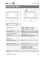
RF-NET Access Point Fitting and Operating Instructions Translated fitting and operating instructions version 1.2, 06/2012 Preface Preface These Fitting and Operating Instructions will help you fit and use the RF-NET Access Point (Access Point) as intended, safely, and advantageously. Any person who fits, operates, or disposes of this Access Point must have read and understood the entire contents of these Fitting and Operating Instructions. These Fitting and Operating Instructions should be kept near the Access Point at all times. Notes on the layout In these Fitting and Operating Instructions, various elements are highlighted with defined layout features so you can identify at a glance whether a passage contains standard text, a list, or individual steps in a sequence of actions. 2 Notes highlighted with this symbol contain additional information on the efficient use of the Access Point. RF-NET Access Point Contents Contents Preface .......................................................................... 2 Notes on the layout ....................................................... 2 For your safety .............................................................. 4 Basic safety instructions .......................................... 4 Explanation of the safety notes ....................................... 6 Intended use ................................................................ 7 Remarks ...................................................................... 7 Manufacturer ................................................................ 7 Service ........................................................................ 7 Introduction .................................................................. 8 Description ................................................................... 8 Components of a wireless system ................................... 10 OMEGA system components .......................................... 11 Scope of delivery.......................................................... 12 Unpacking the Access Point ........................................... 13 Connections ................................................................. 13 RF ranges .................................................................... 14 Fitting the Access Point ............................................... 16 Trouble shooting ......................................................... 23 Maintenance ................................................................ 26 Spare Parts .................................................................. 26 Disposal ....................................................................... 26 Technical data ............................................................. 27 Glossary ...................................................................... 28 Notes on the manufacturer's warranty ........................ 29 RF-NET Access Point 3 For your safety For your safety Basic safety instructions Observe all warnings and notes in these Fitting and Operating Instructions. Always keep these Fitting and Operating Instructions near the Access Point. To prevent danger to life and limb, the following safety instructions must be observed: Danger of explosion Live parts of the Access Point may cause an explosion. Do not use the Access Point in potentially explosive atmospheres. Danger of suffocation Never allow children to play with packaging material and/or plastic bags. There is a risk that children pull them over their head and suffocate. Danger of poisoning Always keep the Access Point out of the reach of children. There is a risk that children swallow small parts such as screws. Danger of property damage To prevent property damage, the following safety instructions should be observed: Always have repairs performed by properly qualified personnel. Only use accessories and spare parts recommended by CEStronics. 4 RF-NET Access Point For your safety Only use the proper tools to open the Access Point. Do not drop the Access Point on the floor, on hard surfaces or on hard objects. Use surge arresters to avoid damage to your Access Point through overvoltage, for example by lightning. Protect the electronic components of the Access Point against water and other liquids. The Access Point contains highly sensitive electronic parts that may be damaged or destroyed through static charges. Do not disassemble the Access Point in rooms with built up static charge. Ensure potential equalization when working on the Access Point to remove any static charge. Do not use the Access Point in corrosive atmospheres (chlorine, ammonia, lime water). Only use the Access Point in rooms in which the humidity does not exceed 95 %. Do not use the Access Point in rooms with a high level of dust formation. Do not use the Access Point near sources of heat. Do not expose the Access Point to temperatures below 0 °C or above +40 °C. Danger of malfunctions Do not cover the housing of the Access Point with any metallic material. Satisfy yourself when installing the Access Point that both the Access Point and all other system components are in perfect working order. Malfunctions of the Access Point and other system components may compromise the functioning of the entire system. If necessary, use uninterrupted power supply (UPS) systems to ensure an uninterrupted operation of your locking system. RF-NET Access Point 5 For your safety Explanation of the safety notes These Fitting and Operating Instructions include safety notes of the following types: CAUTION CAUTION notes warn against hazards that may result in slight or medium injuries. Notes NOTICE Notes warn against possible property or environmental damage. 6 RF-NET Access Point For your safety Intended use The Access Point serves to transmit data between locking devices and the control centre of your OMEGA ACTIVE system. Between the Access Point and the locking devices, data are transmitted via 868 MHz radio signals. The connection of the Access Point to the master computer is wired. It is exclusively intended and may only be used for that purpose. Any other use is considered to be improper and may result in property damage or even personal injury. CEStronics GmbH does not accept any liability for any damage resulting from improper use. Remarks This fitting and operating instructions are only valid for: CEStronics RF-NET Access Point Manufacturer The manufacturer from the Access Point is: CEStronics GmbH Friedrichstr. 243 42551 Velbert Tel: +49 (0) 2051-204-0 Fax: +49 (0) 2051-204-105 www.ces.eu Service For support in case of service please contact your CEStronics partner. RF-NET Access Point 7 Introduction Introduction Description The Access Point is part of the OMEGA-system. It establishes the connection between the OMEGA locking devices and the overall control centre via a radio frequency (RF) link. The master computer is a commercial PC with the OMEGA software. The Access Point is connected with the control centre via an RJ45-Ethernet cable (10/100 MBit). The Access Point is thus the network interface of the system. The desired access authorizations are created in the control centre and transmitted via the Ethernet to the Access Points. The Access Points then transmit the authorizations over the RF link to the locking devices. In return, the log data are retrieved from the cylinders and then fed back to the control centre via the Ethernet. The wide range of the Access Points allows a wireless deployment of locking cylinders and wall terminals. No further installation work on your doors is required. Parts of the software are covered by the BSD license. Please notice the copyright notices under: copying liquorice.txt and copying-gpl.txt. 8 RF-NET Access Point Introduction Other features of the Access Point: Integrated 868 MHz RF transceiver. The maximum RF range to the locking devices is 25 metres. Power supply of the Access Point with the supplied power pack. No other power supplies are permitted. Two colour LEDs at the Ethernet connection for visual signalization of data traffic. Available accessories for the Access Point: D-LAN™ adapter (System Powerline, to implement IP networks using the 230 V power network). This option makes it possible to transmit the network signal via the 230 V power network using suitable adapters. This means that no separate network cables must be installed. PoE (Power over Ethernet) adapter. To reduce the installation expense and increase the failure prevention you can supply the Access Point with power via the network interface. This eliminates the need to use the plug-in power supply. The stated reading ranges of 25 m cannot be guaranteed as the reading range depends on the local building conditions. CEStronics recommends to have your building situation checked by your professional CEStronics partner. For further information on the available options, please contact your CEStronics partner. RF-NET Access Point 9 Introduction Components of a wireless system Access Points establish the connection between your control centre (PC) and your locking devices. The following components are required for the system: Standard PC (No. 1, 2) with Windows XP™, Windows 7/32 Bit™ Network card (TCP/IP) Monitor with a resolution of 1024 768 pixel or higher OMEGA Access Points (pos. 3, maximum ten points of entry per Access Point), additional Repeaters if applicable OMEGA software At least one locking device (No. 4). For further information, please refer to the OMEGA software User Manual. 10 RF-NET Access Point Introduction OMEGA system components The following shows the components that can be combined within the OMEGA system: These options can be purchased from a CEStronics partner to match your specific requirements. 1 Locking media (optional): Your locking devices can be operated with the following locking media: Transponder key, key fob, card. 2 Locking devices (optional) 3 Access Point 4 RF-NET Repeater to extend the range of Access Points (optional) 5 Standard-PC (optional) 6 With the SYSTEM-MASTER, you can authorize PROGRAMMASTERS. For each locking system, there is one and only one valid SYSTEM-MASTER. 7 The PROGRAM-MASTER is used to authorize and delete the authorization of your locking media. RF-NET Access Point 11 Introduction Scope of delivery Before proceeding with fitting and commissioning, please check the contents of the package and the scope of delivery. Check new devices for transport damage and inform your CEStronics partner promptly if any damage is found. Device overview 1 2 Access Point Plug-in power supply with connection cable Case parts 12 1 Housing top 2 Housing base 3 Wall holder RF-NET Access Point Introduction Unpacking the Access Point Take the Access Point out of the package and remove any packaging material such as film, padding and packaging board. NOTICE Risk of damage to the Access Point. Only use the supplied power pack for the power supply of your Access Point. Connections 1 2 3 4 Socket for the plug-in power supply Socket for the network cable (RJ45), Indication of network connection LEDs for signaling RF traffic and operating state Screw terminal for the antenna RF-NET Access Point 13 Introduction RF ranges Ensure that the permissible RF ranges are observed. Install the devices within the maximum RF range of 25 metres. Checking the range The optional RF-TRACE-MASTER transponder card allows you to check the quality of the radio frequency (RF) link between the OMEGA server and your locking devices. The RF-TRACE-MASTER triggers the following signals of your locking devices: Green LED of your locking cylinder, IES fitting or wall terminal flashes twice: strong RF link. Green LED of your locking cylinder, IES fitting or wall terminal flashes once: adequate RF link. If the red LED of your locking device flashes, the RF link is not OK and must be checked. 14 RF-NET Access Point Introduction If the red and the green LEDs flash alternately or simultaneously, the RF link is weak and should be checked to ensure full functionality and reliability. To verify the quality of the RF link to your locking devices, proceed as follows: Hold the RF-TRACE-MASTER for about two seconds in front of your locking cylinder or wall terminal. The function is performed immediately. RF-NET Access Point 15 Fitting the Access Point Fitting the Access Point NOTICE If an Access Point fails, your locking devices cannot be reached any more. Make sure that the Access Points are always easily accessible. Make sure that all electrical connections can be separated at any time. NOTICE The Access Point may be damaged if not fitted properly. Only skilled personnel may fit the Access Point. This personnel must have been trained on the product by CEStronics or a CEStronics partner. NOTICE Static charges may damage or interfere with the electronic components of the Access Point. Do not disassemble the Access Point in rooms with built up static charge. Ensure potential equalization when working on the Access Point to remove any static charge. 16 RF-NET Access Point Fitting the Access Point When fitting the Access Point, you must ensure the following conditions: Make sure that the power supply and the power supply cable can be plugged in. Make sure that the network cable can be plugged in. The Access Point must not be fitted on metallic surfaces. Always install the Access Point as far away from ground potentials as possible to avoid interference with the radio traffic. The Access Point may not be fitted outdoors. The Access Point is supplied preassembled. To commission your Access Point, you only have to fasten the wall mount at a suitable position and push on the Access Point. In addition, you require suitable fasteners for the Access Point. The fasteners and the related tools required depend on the material at the place of installation. Purchase suitable fasteners material from your specialized dealer for fastening engineering. CAUTION Danger of injury by improper fitting. Ensure that the Access Point is only fitted by appropriately trained skilled personnel. RF-NET Access Point 17 Fitting the Access Point The Access Point must be fitted at an easily accessible location, e.g. near a ceiling or on a wall. A suitable fitting position is for instance above a door frame, at a height of about 2 metres and with as much distance to the nearest object or wall as possible. If the reception is good, install the Access Point with the ports pointing upwards. However, also all other orientations are possible, such as with the antenna pointing to the side or downwards as shown in the figure. Wherever possible, you should check the reception before the final fastening to determine the orientation of the Access Point and the antenna. For this purpose, put the Access Point temporarily into service (see page 20 ff). 18 RF-NET Access Point Fitting the Access Point Verify the reception at your locking devices with the optional RF-TRACE-MASTER (see page 14). The orientation of the antenna can be adjusted. As long as the antenna has not yet been screwed in tight, it can be rotated by 360°. After it has been tightened, the antenna can only be aligned vertically and horizontally. If the RF link is satisfactory, fit the Access Point permanently in the determined position: Fasten the wall mount with suitable fasteners at a right angle at its proper position. RF-NET Access Point 19 Fitting the Access Point Push the Access Point onto the wall mount. The Access Point only sits properly after it has snapped in the wall mount. Do not yet screw the antenna (1) tight in the antenna base (2) at this point. Do not use any tools for tightening. Establish the required cable connections as described on page 13. Put the Access Point into service. 20 RF-NET Access Point Fitting the Access Point Check the orientation of the antenna to ensure sufficient effective radiated power. Use the optional RF-TRACE-MASTER to check the effective radiated power (see also note on page 14 "Checking the range"). Orientate the antenna so that your locking devices receive the maximum effective radiated power. As long as the antenna has not yet been screwed in tight, you can rotate it by 360° and align it vertically and horizontally. Once you have found the best position of the antenna, tighten it with your hand. Never use a tool to tighten the antenna. The antenna is tight if it can no longer be rotated. NOTICE The printed circuit board of Access Point may be damaged through mechanical forces. Be careful not to damage the printed circuit board when fitting the case. RF-NET Access Point 21 Fitting the Access Point If possible, verify the perfect functioning of the Access Point already at this stage: Normal operation Signal location Meaning Is the network connection available? Is the Access Point operative? The two LEDs signal the following conditions: Signal Meaning Green LED, permanent Network connection established (perfect connection to the OMEGA server) Operative Data transmission in progress Red LED, flashing Red LED, flashes short/ flickers Is a data link available? The two LEDs signal the following Ethernet interface conditions: 22 Left hand side Right hand side Colour Meaning Colour Meaning OFF no connection OFF no connection Green Network connection established Orange Data transmission in progress RF-NET Access Point Trouble shooting Trouble shooting Symptom Possible cause and remedy No connection to the locking devices can be established. Your connection cables are mechanically damaged or broken. Check the installation for broken wires or faulty connections. Check the continuity of your wires with a suitable instrument (multimeter, ohmmeter). Verify the proper functioning of the plug-in power supply of the Access Point with a suitable instrument (multimeter, ohmmeter). Check the plug-in power supply for mechanical damage. Check the signalization of the LEDs. Eliminate any interruptions and correct any damage found. In case of mechanical damage, have your Access Point repaired by your CEStronics partner. The Access Point has no connection to the power supply and/or the network. Check the terminals and connections. Establish missing connections. Check the signalization of the LEDs. RF-NET Access Point 23 Trouble shooting Locking devices are outside the radio frequency range of Access Points. Reduce the distance to your locking devices. Verify the quality of the wireless transmission with the optional RFTRACE-Master. The locking devices have no power. Check the power supply of your locking devices. Re-establish the proper power supply of your locking devices. For further information on establishing the power supply, please refer to the operating instructions of your locking devices. Replace any flat batteries of your locking devices. For further information on the replacement of batteries, please refer to the operating instructions of your locking devices. 24 RF-NET Access Point Trouble shooting The OMEGA software is not configured correctly. Your PC does not work properly. Check the software settings as described in the OMEGA User Manual. Check the functioning of the software as described in the OMEGA User Manual. Verify the perfect functioning of your PC. If you are not able to verify the perfect functioning, please contact your PC dealer. Your locking devices do not operate in RF mode. Use the optional RF-INI-MASTER to enable the RF mode of your locking devices. If the trouble still cannot be eliminated, please contact your CEStronics partner. RF-NET Access Point 25 Maintenance Maintenance Have the Access Point serviced and its perfect functioning verified every six months by CEStronics or by a CEStronics partner only. Spare Parts The Access Point does not require any spare parts for you to change. If you need service, please contact your professional CES partner. Disposal Neither the Access Point, nor any parts of the Access Point may be discarded with the normal household waste. Ask your local authorities about recycling and/or the proper disposal of the device in line with environmental regulations. 26 RF-NET Access Point Technical data Technical data Dimensions: Power supply: Power consumption Connection: Communication frequency: Network protocol: Length: approx. 117 mm, Width: approx. 107 mm, Height: approx. 24 mm 9 V DC Only via the power pack supplied Max. 1,0 W Phonoplug 5.5 2.1 mm 5.5 mm: -, 2.1 mm: + Sending/transmitting 868 MHz TCP/IP RF range: approx. 25 m Temperature rage: Environmental conditions: 0 °C to + 40 °C Not suitable for use in corrosive atmospheres (chlorine, ammonia, lime water). Maximum air humidity: 95 % At least 10 years Service life of the Access Point: RF-NET Access Point 27 Glossary Glossary Locking devices Locking devices are locking cylinders electronic shields and wall terminals. If these are operating in RF mode, the Access Point can be linked with them. Reader module The reader module is installed in the outside knob of the locking cylinder or in the wall terminal. It detects your locking media. Master media Cards to program your locking devices. The OMEGA system comprises two types of Master media, the SYSTEMMASTER and the PROGRAM-MASTER. Optional transponder cards also have Master medium status. Locking medium A medium with which you can lock and unlock an electronic locking cylinder and/or a wall terminal. SYSTEM-MASTER Master medium used to authorize PROGRAM-MASTERS for the system. For each locking system, there is one and only one SYSTEM-MASTER. Transponder A transponder is a wireless communication or control medium that receives signals and automatically responds to them. RF-TRACE-Master An optional Master card which enables you to test the quality of your RF link. RF range The distance within which a safe transmission of data is possible. 28 RF-NET Access Point Notes on the manufacturer's warranty Notes on the manufacturer's warranty As stated in our Standard Terms and Conditions, the manufacturer's warranty does not extend to the following types of damage: damage to outer mechanical parts and damage resulting from normal wear and tear damage as a consequence of external events or influence damage as a consequence of improper operation damage as a consequence of excess voltage damage as a consequence of fire, water or smoke. All technical data and features are subject to change without notice. The information and data contained in this document are subject to change without notice. Without the express written permission by CEStronics, no part of this document may be copied or transmitted for any purpose. © 2011 CEStronics GmbH, Velbert/Germany BRO2221-002 RF-NET Access Point 29 C. Ed. Schulte GmbH Zylinderschloßfabrik Friedrichstraße 243 D-42551 Velbert +49 (0)2051-204-0 +49 (0)2051-204-229 @ [email protected] www.ces.eu CESfrance SARL 8 Impasse Charles Petit F-75011 Paris +33 (0)1-44 87 07 56 +33 (0)1-43 07 35 78 @ [email protected] www.ces.eu/fr CEStronics GmbH Friedrichstraße 243 D-42551 Velbert +49 (0)2051-204-0 +49 (0)2051-204-229 @ [email protected] CESnederland B.V. Lage Brink 9 NL- 7317 BD Apeldoorn +31 (0)55-52 66 89-0 +31 (0)55-52 66 89-9 @ [email protected] www.ces.eu/nl CESlocks GmbH Mettmanner Str. 119 D-42549 Velbert +49 (0)2051-204-0 +49 (0)2051-204-229 @ [email protected] CESitalia srl V.d. vecchie Fondamenta, 4 Straße d.A. Gründungen 4 I-39044 Egna / Neumarkt (BZ) +39 0471-812 294 +39 0471-812 294 @ [email protected] www.ces.eu/it CESrom srl. Str. Metalurgistilor 3 D RO-550137 Sibiu +40 (0)269-206 00-2 +40 (0)269-206 00-5 @ [email protected] CES Security Solutions Ltd. Unit 6-8 Revenge Road GB-Lordswood, Chatham Kent ME58UD +44 (0)1634-673301 +44 (0)1634-673326 @ [email protected] www.ces.eu/en CES Austria Repräsentanz Österreich Cesar A.Carcamo +43 (0660)7320311 +43 (0732)210022-2681 @ [email protected] www.beschlaege.cc CES MIDDLE EAST A.G.P Advanced German Products LLC Authorized General Distributor of CES in Middle East PO Box 102761 UAE Dubai +971 (0) 4 369 7051 +971 (0) 4 390 8935 @ [email protected] www.agp-dubai.com