1
DMA8Plus Digital
Media Adapter
Installation and User’s
Manual
Issue 2
Part Number 91805
Dolby Laboratories, Inc.
Corporate Headquarters
Dolby Laboratories, Inc.
100 Potrero Avenue
San Francisco, CA 94103‐4813 USA
Telephone 415‐558‐0200
Fax 415‐863‐1373
www.dolby.com
European Headquarters
Dolby Laboratories, Inc.
Wootton Bassett
Wiltshire SN4 8QJ England
Telephone 44‐1793‐842100
Fax 44‐1793‐842101
DISCLAIMER OF WARRANTIES:
EQUIPMENT MANUFACTURED BY DOLBY LABORATORIES IS WARRANTED AGAINST DEFECTS IN MATERIALS AND WORKMANSHIP FOR A PERIOD OF ONE YEAR FROM THE DATE OF PURCHASE. THERE ARE NO OTHER EXPRESS OR IMPLIED WARRANTIES AND NO WARRANTY OF MERCHANTABILITY OR FITNESS FOR A PARTICULAR PURPOSE, OR OF NONINFRINGEMENT OF THIRD‐PARTY RIGHTS (INCLUDING, BUT NOT LIMITED TO, COPYRIGHT AND PATENT RIGHTS).
LIMITATION OF LIABILITY: IT IS UNDERSTOOD AND AGREED THAT DOLBY LABORATORIES’ LIABILITY, WHETHER IN CONTRACT, IN TORT, UNDER ANY WARRANTY, IN NEGLIGENCE, OR OTHERWISE, SHALL NOT EXCEED THE COST OF REPAIR OR REPLACEMENT OF THE DEFECTIVE COMPONENTS OR ACCUSED INFRINGING DEVICES, AND UNDER NO CIRCUMSTANCES SHALL DOLBY LABORATORIES BE LIABLE FOR INCIDENTAL, SPECIAL, DIRECT, INDIRECT, OR CONSEQUENTIAL DAMAGES (INCLUDING, BUT NOT LIMITED TO, DAMAGE TO SOFTWARE OR RECORDED AUDIO OR VISUAL MATERIAL), COST OF DEFENSE, OR LOSS OF USE, REVENUE, OR PROFIT, EVEN IF DOLBY LABORATORIES OR ITS AGENTS HAVE BEEN ADVISED, ORALLY OR IN WRITING, OF THE POSSIBILITY OF SUCH DAMAGES.
Dolby, Pro Logic, and the double‐D symbol are registered trademarks of Dolby Laboratories. All other trademarks remain the property of their respective owners.
© 2007 Dolby Laboratories. All rights reserved.
ii
Part Number 91805
Issue 2
S07/18348/18506
Dolby® DMA8Plus Digital Media Adapter Installation and User’s Manual
Regulatory Notices
FCC
NOTE: This equipment has been tested and found to comply with the limits for a Class A digital device, pursuant to Part 15 of the FCC Rules. These limits are designed to provide reasonable protection against harmful interference when the equipment is operated in a commercial environment. This equipment generates, uses, and can radiate radio frequency energy and, if not installed and used in accordance with this instruction manual, may cause harmful interference to radio communications. Operation of this equipment in a residential area is likely to cause harmful interference in which case the user will be required to correct the interference at his own expense.
Canada
This Class A digital apparatus complies with Canadian ICES‐003.
EU/EMC
This unit complies with the EMC requirement of EN55103‐1 and EN55103‐2 when operated in an E2 environment in accordance with this manual.
Important Safety Instructions
1. Read these instructions.
2. Keep these instructions.
3. Heed all warnings.
4. Follow all instructions.
5. Do not use this apparatus near water.
6. WARNING: To reduce the risk of fire or electric shock, do not expose this apparatus to rain or moisture.
7. Clean only with dry cloth.
8. Do not install near any heat sources such as radiators, heat registers, stoves, or other apparatus (including amplifiers) that produce heat.
9. No naked flame sources, such as lighted candles, should be placed on the apparatus
10. Protect the power cord from being walked on or pinched particularly at plugs, convenience receptacles, and the point where they exit from the apparatus.
11. Only use attachments/accessories specified by the manufacturer.
12. Unplug this apparatus during lightning storms or when unused for long periods of time.
13. Refer all servicing to qualified service personnel. Servicing is required when the apparatus has been damaged in any way, such as power‐supply cord or plug is damaged, liquid has been spilled or objects have fallen into the apparatus, the apparatus has been exposed to rain or moisture, does not operate normally, or has been dropped.
14. Do not expose the apparatus to dripping or splashing and no objects filled with liquids, such as vases, shall be placed on the apparatus.
Dolby® DMA8Plus Digital Media Adapter Installation and User’s Manual
iii
Regulatory Notices
15. CAUTION: Troubleshooting must be performed by a trained technician. To reduce the risk of electric shock, do not attempt to service this equipment unless you are qualified to do so.
16. Do not defeat the safety purpose of the polarized or grounding‐type plug. A polarized plug has two blades with one wider than the other. A grounding type plug has two blades and a third grounding prong. The wide blade or the third prong is provided for your safety. If the provided plug does not fit into your outlet, consult an electrician for replacement of the obsolete outlet.
17. This apparatus must be earthed (grounded) by connecting to a correctly wired and earthed power outlet.
18. Ensure that your mains supply is in the correct range for the input power requirement of the unit.
19. In order to reduce the risk of electrical shock, the power cord must be disconnected when the power supply assembly is removed.
20. This equipment is designed to mount in a suitably ventilated 19” rack; ensure that any ventilation slots in the unit are not blocked or covered.
21. The mains power disconnect device for this unit is the plug‐in mains cord rather than a power switch. The mains cord must remain readily accessible for disconnecting mains power.
22. To avoid exposure to dangerous voltages and to avoid damage to the unit, do not connect the rear‐panel Ethernet port to telephone circuits.
23. As the colours of the cores in the mains lead may not correspond with the coloured markings identifying the terminals in your plug, proceed as follows:
•
The green and yellow core must be connected to the terminal in the plug identified by the letter E, or by the earth symbol , or coloured green, or green and yellow.
•
The blue core must be connected to the terminal marked with the letter N or coloured black.
•
The brown core must be connected to the terminal marked with the letter L or coloured red.
24. This apparatus must be earthed.
Fuses
WARNING: Check that the correct fuses have been installed. For continued protection against risk of fire, replace only with fuses of the same type and rating. For details on fuse ratings and instructions on fuse replacement, see Checking the Two User‐Serviceable Fuses on page 10.
WEEE
PRODUCT END‐OF‐LIFE INFORMATION
This product was designed and built by Dolby Laboratories to provide many years of service, and is backed by our commitment to provide high‐quality support. When it eventually reaches the end of its serviceable life, it should be disposed of in accordance with local or national legislation.
For current information please visit our website at: http://www.dolby.com/environment.
iv
Dolby® DMA8Plus Digital Media Adapter Installation and User’s Manual
Regulatory Notices
IMPORTANT SAFETY NOTICE
This unit complies with safety standard EN60065 as appropriate. The unit shall not be exposed to dripping or splashing and no objects filled with liquids, such as coffee cups, shall be placed on the equipment. To ensure safe operation and to guard against potential shock hazard or risk of fire, the following must be observed:
o
Ensure that your mains supply is in the correct range for the input power requirement of the unit. o
o
o
Ensure fuses fitted are the correct rating and type as marked on the unit.
The unit must be earthed by connecting to a correctly wired and earthed power outlet.
The power cord supplied with this unit must be wired as follows:
Live—Brown Neutral—Blue Earth—Green/Yellow
GB
IMPORTANT – NOTE DE SECURITE
Ce materiel est conforme à la norme EN60065. Ne pas exposer cet appareil aux éclaboussures ou aux gouttes de liquide. Ne pas poser dʹobjets remplis de liquide, tels que des tasses de café, sur lʹappareil. Pour vous assurer dʹun fonctionnement sans danger et de prévenir tout choc électrique ou tout risque dʹincendie, veillez à observer les recommandations suivantes.
F
o
Le selecteur de tension doit être placé sur la valeur correspondante à votre alimentation réseau.
o
Les fusibles doivent correspondre à la valeur indiquée sur le materiel.
o
Le materiel doit être correctement relié à la terre.
o
Le cordon secteur livré avec le materiel doit être cablé de la manière suivante:
Phase—Brun Neutre—Bleu Terre—Vert/Jaune WICHTIGER SICHERHEITSHINWEIS
Dieses Gerät entspricht der Sicherheitsnorm EN60065. Das Gerät darf nicht mit Flüssigkeiten (Spritzwasser usw.) in Berührung kommen; stellen Sie keine Gefäße, z.B. Kaffeetassen, auf das Gerät. Für das sichere Funktionieren des Gerätes und zur Unfallverhütung (elektrischer Schlag, Feuer) sind die folgenden Regeln unbedingt einzuhalten:
D
o
Der Spannungswähler muß auf Ihre Netzspannung eingestellt sein.
o
Die Sicherungen müssen in Typ und Stromwert mit den Angaben auf dem Gerät übereinstimmen.
o
Die Erdung des Gerätes muß über eine geerdete Steckdose gewährleistet sein.
o
Das mitgelieferte Netzkabel muß wie folgt verdrahtet werden:
Phase—braun Nulleiter—blau Erde—grün/gelb
NORME DI SICUREZZA – IMPORTANTE
Questa apparecchiatura è stata costruita in accordo alle norme di sicurezza EN60065. Il prodotto non deve essere sottoposto a schizzi, spruzzi e gocciolamenti, e nessun tipo di oggetto riempito con liquidi, come ad esempio tazze di caffè, deve essere appoggiato sul dispositivo. Per una perfetta sicurezza ed al fine di evitare eventuali rischi di scossa êlettrica o dʹincendio vanno osservate le seguenti misure di sicurezza:
o
Assicurarsi che il selettore di cambio tensione sia posizionato sul valore corretto.
I
o
Assicurarsi che la portata ed il tipo di fusibili siano quelli prescritti dalla casa costruttrice.
o
Lʹapparecchiatura deve avere un collegamento di messa a terra ben eseguito; anche la connessione rete deve avere un collegamento a terra.
o
Il cavo di alimentazione a corredo dellʹapparecchiatura deve essere collegato come segue:
Filo tensione—Marrone Neutro—Blu Massa—Verde/Giallo
AVISO IMPORTANTE DE SEGURIDAD
Esta unidad cumple con la norma de seguridad EN60065. La unidad no debe ser expuesta a goteos o salpicaduras y no deben colocarse sobre el equipo recipientes con liquidos, como tazas de cafe. Para asegurarse un funcionamiento seguro y prevenir cualquier posible peligro de descarga o riesgo de incendio, se han de observar las siguientes precauciones: o
Asegúrese que el selector de tensión esté ajustado a la tensión correcta para su alimentación.
E
o
Asegúrese que los fusibles colocados son del tipo y valor correctos, tal como se marca en la unidad.
o
La unidad debe ser puesta a tierra, conectándola a un conector de red correctamente cableado y puesto a tierra.
o
El cable de red suministrado con esta unidad, debe ser cableado como sigue:
Vivo—Marrón Neutro—Azul Tierra—Verde/Amarillo
VIKTIGA SÄKERHETSÅTGÄRDER!
Denna enhet uppfyller säkerhetsstandard EN60065. Enheten får ej utsättas för yttre åverkan samt föremål innehållande vätska, såsom kaffemuggar, får ej placeras på utrustningen. För att garantera säkerheten och gardera mot eventuell elchock eller brandrisk, måste följande observeras:
o
o
o
o
Kontrollera att spänningsväljaren är inställd på korrekt nätspänning.
Konrollera att säkringarna är av rätt typ och för rätt strömstyrka så som anvisningarna på enheten föreskriver.
Enheten måste vara jordad genom anslutning till ett korrekt kopplat och jordat el‐uttag.
El‐sladden som medföljer denna enhet måste kopplas enligt foljande:
Fas—Brun Neutral—Blå Jord—Grön/Gul
S
BELANGRIJK VEILIGHEIDS‐VOORSCHRIFT:
Deze unit voldoet aan de EN60065 veiligheids‐standaards. Dit apparaat mag niet worden blootgesteld aan vocht. Vanwege het risico dat er druppels in het apparaat vallen, dient u er geen vloeistoffen in bekers op te plaatsen. Voor een veilig gebruik en om het gevaar van electrische schokken en het risico van brand te vermijden, dienen de volgende regels in acht te worden genomen:
o
Controleer of de spanningscaroussel op het juiste Voltage staat.
o
Gebruik alleen zekeringen van de aangegeven typen en waarden.
o
Aansluiting van de unit alleen aan een geaarde wandcontactdoos.
o
De netkabel die met de unit wordt geleverd, moet als volgt worden aangesloten:
Fase—Bruin Nul—Blauw Aarde—Groen/Geel
NL
Dolby® DMA8Plus Digital Media Adapter Installation and User’s Manual
v
Table of Contents
Chapter 1: Introduction
1.1
1.2
DMA8Plus Front Panel .........................................................................................................2
1.1.1
Digital Input Push Buttons........................................................................................2
1.1.2
Film Push Button......................................................................................................3
1.1.3
Valid Input Clock .....................................................................................................3
1.1.4
Output Activity LEDs ................................................................................................3
1.1.5
Format LEDs............................................................................................................3
1.1.6
Decode Mode LEDs.................................................................................................3
1.1.7
USB Port ..................................................................................................................3
DMA8Plus Rear Panel ..........................................................................................................4
1.2.1
To CP Control Connector.........................................................................................4
1.2.2
To DA Control Connector.........................................................................................4
1.2.3
4xAES Input (AES/EBU) ..........................................................................................5
1.2.4
1xAES Inputs (AES3)...............................................................................................5
1.2.5
S/PDIF Optical Input ................................................................................................5
1.2.6
Digital Media Automation Connector .......................................................................5
1.2.7
RS-232 Serial Port ...................................................................................................5
1.2.8
Ethernet Port............................................................................................................5
1.2.9
Audio Out to CP Connector .....................................................................................6
1.2.10 Analog Audio In Connector ......................................................................................6
Chapter 2: Installation and Maintenance
2.1
2.2
2.3
2.4
2.5
2.6
DMA8Plus Floating Signal Grounds .....................................................................................7
Digital Audio Inputs ...............................................................................................................7
2.2.1
Consumer Interface Standards for Digital Audio......................................................8
2.2.2
Cable Issues ............................................................................................................8
2.2.3
Multiple Sources: Conversion Between Interface Standards...................................8
Connections ..........................................................................................................................9
Fuse Information ...................................................................................................................9
2.4.1
Checking the Two User-Serviceable Fuses...........................................................10
Mains Power Wiring ............................................................................................................11
Wiring Diagrams .................................................................................................................11
Chapter 3: Setting up the DMA8Plus
3.1
3.2
3.3
3.4
3.5
DMA8Plus Setup Software ................................................................................................19
Installing and Running the Setup Software.........................................................................20
Profile .................................................................................................................................20
3.3.1
Profile Settings.......................................................................................................21
3.3.2
Virtual Status Monitor.............................................................................................21
Network...............................................................................................................................22
Digital Inputs 1, 2, 3, and 4 .................................................................................................23
3.5.1
Global Delay ..........................................................................................................24
Dolby® DMA8Plus Digital Media Adapter Installation and User’s Manual
vii
Table of Contents
3.5.2
PCM Settings .........................................................................................................24
3.5.3
Dolby Digital Settings.............................................................................................25
3.5.4
Dolby E Settings ....................................................................................................26
3.6
Global Settings....................................................................................................................26
3.6.1
CP Settings ............................................................................................................27
3.6.2
Surround Delay ......................................................................................................27
3.6.3
Pro Logic/Pro Logic II Subwoofer ..........................................................................27
3.6.4
Power-on Mode......................................................................................................27
3.7
File Menu ............................................................................................................................28
3.7.1
Loading Settings ....................................................................................................28
3.7.2
Saving Settings ......................................................................................................28
3.8
Action Menu ........................................................................................................................29
3.8.1
Connecting to a Local or Remote Device ..............................................................29
3.8.2
Update Software ....................................................................................................29
3.9
Window Menu .....................................................................................................................30
3.10 Updating the DMA8Plus Firmware......................................................................................31
Chapter 4: Technical Reference
4.1
4.2
4.3
viii
DMA8Plus Specifications....................................................................................................33
Rear-Panel Connector Descriptions and Types..................................................................36
4.2.1
Digital Media Automation Connector .....................................................................36
4.2.2
Analog Audio In/Out Connectors ...........................................................................37
4.2.3
4xAES In Connector ..............................................................................................38
4.2.4
Remote RS-232 Serial Port ...................................................................................39
4.2.5
Automation Connections—CP55 with Cat. No. 321 Interface................................39
4.2.6
Cinema Processor Automation Pin Assignments ..................................................40
4.2.7
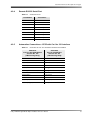
RS-232 ASCII String Commands...........................................................................42
4.2.8
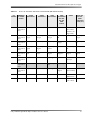
To CP Control Pinouts ...........................................................................................43
4.2.9
DMA8Plus Audio Out to CP Pinouts ......................................................................44
Remote Commands and Control ........................................................................................46
4.3.1
Serial......................................................................................................................46
4.3.2
Ethernet .................................................................................................................46
Dolby® DMA8Plus Digital Media Adapter Installation and User’s Manual
List of Figures
Figure 1-1
Figure 1-2
Figure 2-1
Figure 3-1
Figure 3-2
Figure 3-3
Figure 3-4
Figure 3-5
Figure 3-6
Figure 3-7
Figure 3-8
Figure 3-9
Figure 3-10
Figure 3-11
Figure 3-12
Figure 3-13
DMA8Plus Front Panel .......................................................................................................... 2
DMA8Plus Rear Panel........................................................................................................... 4
Checking the User-Serviceable Fuses ................................................................................ 10
Installation Welcome Screen ............................................................................................... 20
Profile Settings Window....................................................................................................... 21
Ethernet Settings Window ................................................................................................... 22
Digital Input 1 Window......................................................................................................... 23
Digital Input 2 Window......................................................................................................... 24
Global Settings Window ...................................................................................................... 26
Selecting Open in the File Menu ......................................................................................... 28
Selecting Save in the File Menu .......................................................................................... 28
Action Menu......................................................................................................................... 29
Connect to Remote DMA8Plus Prompt ............................................................................... 29
Window Menu...................................................................................................................... 30
Expert View Window............................................................................................................ 30
Dolby Software Update Screen ........................................................................................... 31
Dolby®DMA8Plus Digital Media Adapter Installation and User’s Manual
ix
List of Tables
Table 1-1
Table 2-1
Table 4-1
Table 4-2
Table 4-3
Table 4-4
Table 4-5
Table 4-6
Table 4-7
Table 4-8
Table 4-9
Table 4-10
Table 4-11
Digital Push Button Functionality............................................................................................ 2
Examples of Available Balanced/Unbalanced Adapters ........................................................ 9
Rear-Panel Connector Descriptions and Types ................................................................... 36
Digital Media Connector Pinout............................................................................................36
Analog Audio In/Out Connector Pinout ................................................................................ 37
4xAES In Connector Pinout..................................................................................................38
Serial Port Pinout ................................................................................................................. 39
CP55 with Cat. No. 321 Automation Interface Card Installed ..............................................39
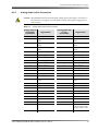
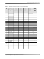
S0–S7 CP Automation Digital Mode Defaults ..................................................................... 40
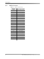
S0–S7 CP Automation Film Mode Format Defaults ........................................................... 41
ASCII String Commands ...................................................................................................... 42
To CP Control (25-pin D output)...........................................................................................43
Audio Out to CP Cables ..................................................................................................... 45
Dolby® DMA8Plus Digital Media Adapter Installation and User’s Manual
x
Chapter 1
Introduction
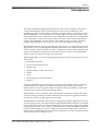
The Dolby® DMA8Plus Digital Media Adapter is a direct result of Dolby Laboratories’ continued leadership in the development of innovative cinema technologies. The DMA8Plus provides all the interface capabilities and digital inputs you’re likely to need. With the DMA8Plus, you can adapt your existing sound system for digital cinema and other digital audio sources. The unit provides a straightforward interface to existing Dolby cinema equipment, such as the CP650, CP500, CP65, CP55, CP45, CP200, and DA20. In addition, the DMA8Plus provides theatres with audio solutions to today’s alternative programming challenges, such as pay‐per‐view events and digital broadcasting.
The DMA8Plus has four separate digital inputs and accepts up to eight channels of PCM digital audio as well as Dolby Digital and Dolby E bitstreams. Two‐channel audio sources can be decoded as discrete, Dolby Pro Logic®, or Dolby Pro Logic II signals. Analog audio outputs are calibrated to cinema processor reference levels to ensure a straightforward interface with your cinema’s existing sound processor.
With the DMA8Plus, you can present high‐quality audio from the following audio sources and formats:
•
Dolby Digital Cinema •
Onscreen advertising servers
•
Digital VTRs
•
Digital satellite or cable TV receivers
•
DVDs
•
PCM •
Dolby Digital consumer bitstreams •
Dolby E
A separate adjustable global audio delay is assigned to each digital input to ensure that sound and picture are perfectly synchronized during digital cinema presentations. Different delays can be assigned to different inputs, providing flexibility for alternative content sources, which often require different delays.
The DMA8Plus is also compatible with existing theatre automation systems and ASCII command strings. Its ability to handle multiple formats and future upgrades make it an essential tool for an evolving digital cinema market. The DMA8Plus is designed to fit between an existing DA20 (Dolby Digital film decoder) and a cinema processor. This allows both the DA20 and DMA8Plus to share the six‐channel input of the cinema processor. When the DMA8Plus is in Film mode, standard six‐channel analog signals from any source, such as a Dolby DA20, are routed through the DMA8Plus to the six‐channel input of a cinema sound processor (pass‐through). In one of the four digital modes, the DMA8Plus decodes and routes signals from a variety of nonfilm sources to the existing cinema sound processor.
Dolby® DMA8Plus Digital Media Adapter Installation and User’s Manual
1
Introduction
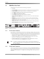
1.1
DMA8Plus Front Panel
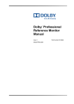
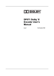
The DMA8Plus front panel includes the following components:
•
Five push buttons to select the input source (digital 1, digital 2, digital 3, digital 4, or film)
•
•
Four LEDs that indicate a valid clock presence for each digital input
Four LEDs that indicate the current format (PCM, Dolby Digital, Dolby E, or Aux [auxiliary])
•
•
Three LEDs that indicate the decode mode (Pro Logic II, Pro Logic, or Discrete)
Eight LEDs that monitor the eight‐channel analog audio output activity (L, C, R, Sw, Ls, Rs, 7 and 8)
•
One USB port for firmware upgrades and setup software
Figure 1‐1
Figure 1-1
DMA8Plus Front Panel
1.1.1
Digital Input Push Buttons
When you press any of the digital 1, digital 2, digital 3, or digital 4 push buttons, that button illuminates, indicating that the selected input is active until you press one of the other push buttons. Pressing a push button selects a specific digital input source, as shown in Table 1‐1. The DMA8Plus sends a format pulse to the cinema processor to switch the processor into the appropriate six‐channel input format (see Table 4‐7).
Note:
Be sure to use a control cable to connect the cinema processor to the DMA8Plus
TO CP CONTROL connector. When in a digital mode, the DMA8Plus can switch between PCM, Dolby Digital, or Dolby E encoded bitstreams. Table 1-1
Digital Push Button Functionality
Digital Push
Button
2
Input Source Selected
digital 1 Selects the digital input source from the 4xAES digital input 1 (four‐channel pairs, 25‐pin D‐connector)
digital 2
Selects the digital input source from the 1xAES digital input 2 (BNC)
digital 3 Selects the digital input source from the 1xAES digital input 3 (BNC)
digital 4 Selects the digital input source from the 1xAES digital input 4 (S/PDIF optical)
Dolby® DMA8Plus Digital Media Adapter Installation and User’s Manual
DMA8Plus Front Panel
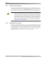
1.1.2
Film Push Button
When you press this button it illuminates, indicating that film mode is active. When the DMA8Plus is in Film mode, audio is received from the analog audio input, which then passes through to the analog audio output (while the unit is in Film mode or when powered off). The DMA8Plus sends a format pulse to the cinema processor to enable an appropriate format (see Table 4‐8). When you press any cinema processor format button, the DMA8Plus switches to Film mode without sending its Film mode pulse assertion.
Note:
Be sure to use a control cable to connect the cinema processor to the DMA8Plus
TO CP CONTROL connector.
1.1.3
Valid Input Clock
Each of the four digital input push buttons has a green valid LED located beneath it. These LEDs illuminate when a valid input clock signal is detected on the respective input (regardless of whether the corresponding button is selected). 1.1.4
Output Activity LEDs
There are eight signal‐level LEDs, one for each channel. The signals are monitored after the D/A converter output, and before the output relays. The LEDs vary in intensity and are brightest at +20 dBr (r = 300 mV), while turning off at approximately –26 dBr.
1.1.5
Format LEDs
There are four bitstream format LEDs (PCM, Dolby Digital, Dolby E, and Aux). The Aux format is currently reserved for future use. These LEDs illuminate when the DMA8Plus is actually receiving the respective data format. 1.1.6
Decode Mode LEDs
There are three bitstream processing LEDs, indicating the decode mode (Pro Logic II, Pro
Logic, and Discrete).
1.1.7
USB Port
The USB port is provided for connecting to a PC. You can use it to set up or update the DMA8Plus firmware. Dolby® DMA8Plus Digital Media Adapter Installation and User’s Manual
3
Introduction
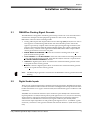
1.2
DMA8Plus Rear Panel
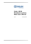
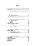
The DMA8Plus rear panel includes the following components:
•
AC input
•
TO CP CONTROL (25‐pin male D‐connector for cinema processor format interface)
•
TO DA CONTROL (25‐pin female D‐connector for DA20 processor interface)
•
One 4xAES (AES/EBU) digital input (25‐pin female D‐connector)
•
Two 1xAES (AES3) digital inputs (BNC)
•
One OPTICAL (S/PDIF) digital input (ToslinkTM connector)
•
DIGITAL MEDIA AUTOMATION (9‐pin female D‐connector from cinema automation control)
•
RS-232 port (9‐pin female D‐connector for control via ASCII command strings)
•
10BASE-T (RJ45 Ethernet port for control through ASCII command strings, Dolby Digital cinema systems, and setup/updates)
•
AUDIO OUT TO CP (25‐pin male D‐connector balanced audio to cinema processor)
•
ANALOG AUDIO IN (25‐pin female D‐connector audio from DA20)
Figure 1‐2
DMA8Plus
Digital Media Adapter
TO CP CONTROL
4xAES IN
1xAES
1xAES
OPTICAL
Dolby, Pro Logic and the double-D symbol
are registered trademarks of Dolby Laboratories.
AUDIO OUT TO CP
DIGITAL MEDIA
AUTOMATION
~ 50–60Hz 15W
100–240 Vac
ACT
TO DA CONTROL
Figure 1-2
DMA8Plus Rear Panel
1.2.1
To CP Control Connector
DIGITAL 1 IN
DIGITAL 2 IN
DIGITAL 3 IN
DIGITAL 4 IN
RS-232
LINK
10BASE-T
ANALOG AUDIO IN
This connector is a 25‐pin male D‐connector for connecting to a Dolby cinema processor’s automation input. It has a floating ground. This output performs the following functions:
•
Prevents a DA20 from reverting the cinema processor to a Dolby SR format while the DMA8Plus is in a digital mode utilizing the cinema processor in Format 10
•
Enables the DMA8Plus to send a film or digital format command to the cinema processor to switch the processor to an associated format
•
Enables the DMA8Plus to receive and activate a film command from a cinema processor when the processor’s format button is activated
Note:
1.2.2
A cable kit is available (US customers only) for connecting the DMA8Plus to a CP650 or CP500 along with your existing automation connection. If you require this kit, order CDMA/D.
To DA Control Connector
This is a 25‐pin female D‐connector for interfacing to a Dolby DA20 CP Sense Control port. It has a floating ground. This interface prevents or blocks a Dolby SR format reversion from a DA20 while the DMA8Plus is in a digital mode, utilizing a Dolby cinema processor in Format 10.
4
Dolby® DMA8Plus Digital Media Adapter Installation and User’s Manual
DMA8Plus Rear Panel
1.2.3
4xAES Input (AES/EBU)
This 25‐pin female D‐connector receives four AES3 streams, which are linked to the digital
1 button. Typically, this input connects to a Dolby Digital cinema server. It accommodates PCM audio at 96, 48, and 44.1 kHz (16, 20, and 24 bit), Dolby Digital at all data rates and sample rates, and Dolby E at frame rates of 23.98 (24 pulldown), 24, 25, 29.97, and 30 fps. The decoding of coded audio is restricted to the first AES3 channel pair. The clocks for all four pairs are derived from pair 1. This connector has a floating ground.
1.2.4
1xAES Inputs (AES3)
These BNC connectors are linked to the digital 2 and digital 3 buttons respectively. They accommodate PCM audio at 96, 48, and 44.1 kHz (16‐, 20‐, and 24‐bit), Dolby Digital at all data rates and sample rates, and Dolby E at frame rates of 23.98 (24 pulldown), 24, 25, 29.97, and 30 fps. A BNC male to RCA female adapter can interface with most consumer gear. These connectors have floating grounds.
1.2.5
S/PDIF Optical Input
This Toslink optical connector is linked to the digital 4 button. It accommodates PCM audio at 96, 48, and 44.1 kHz (16‐, 20‐, and 24‐bit), Dolby Digital at all data rates and sample rates, and Dolby E at frame rates of 23.98 (24 pulldown), 24, 25, 29.97, and 30 fps.
1.2.6
Digital Media Automation Connector
This interface connects to a theatre automation system. It is a 9‐pin female D‐connector providing ground‐switching control of the front‐panel input selection buttons. It has a floating ground. The automation system can switch between film sound (pass‐through) and any of the four digital media sources. This function duplicates the front‐panel digital input buttons and the film button. Two pins (6, 7) provide relay dry contact closure whenever you select either digital 1, digital 2, digital 3, or digital 4 (the relay contacts open when Film mode is selected) for CP200 digital subwoofer logic control. 1.2.7
RS-232 Serial Port
You can use this port for serial control using ASCII string commands. Set this port to 9600 and 8 1 and use a pin‐to‐pin serial cable. You can also perform the same function using the Ethernet port, as described in Section 1.2.8.
1.2.8
Ethernet Port
This is an illuminated RJ45 10BASE‐T Ethernet port with activity LEDs, which provides an interface to a Dolby Digital Cinema network and also serial control through telnet protocol to port 61412. You can also use this port for setup software and firmware upgrades. Dolby® DMA8Plus Digital Media Adapter Installation and User’s Manual
5
Introduction
1.2.9
Audio Out to CP Connector
This connector is an eight‐channel analog output (L, C, R, Ls, Rs, SW, and unassigned channels 7 and 8), which is present on a male 25 pin D‐connector (300 mV reference level). This is either the audio received from the ANALOG AUDIO IN port (Film mode) or the audio converted from one of the digital input sources. This connector has a floating ground. Caution: When connecting the DMA8Plus to a CP45, CP55, CP65, or CP200, be sure to ground the negative side of all audio channels. Failure to do so will result in a reduced audio output level (approximately –6 dB) for that channel. The original audio cables for these processors (DA20 to CP audio cables) were designed for unbalanced audio. As a result, not all grounds are connected to the negative side of the associated channel. You can insert the Cat. No. 757 audio cable adapter dongle with the existing audio output cable to ensure proper grounding of all CP45, CP55, CP65, or CP200 channels. For more information, see DMA8Plus Audio Out to CP Pinouts on page 44.
1.2.10
Analog Audio In Connector
This is an eight‐channel analog input (L, C, R, Ls, Rs, SW, and unassigned channels 7 and 8) designed to receive 300 mV(ref) inputs from a DA20 or other external sources and inputs on a female 25‐pin D‐connector. This analog input signal passes through the DMA8Plus (when in film mode) via relay contacts. These relay contacts are normal to “pass‐through” when the DMA8Plus is not powered on. This connector’s ground passes through the AUDIO OUT TO CP connector in film mode, and is otherwise floating.
6
Dolby® DMA8Plus Digital Media Adapter Installation and User’s Manual
Chapter 2
Installation and Maintenance
2.1
DMA8Plus Floating Signal Grounds
The DMA8Plus is designed to eliminate ground loops, which can occur when the unit is connected to multiple external equipment grounds. For this reason, the following DMA8Plus connectors have isolated grounds:
•
Analog audio inputs and outputs: When in Pass‐Through (film) mode, the low side of each signal is switched along with the hot side. Note that the positive side of the signal is capacitively coupled. If the external signal passing through is balanced, the output is also balanced. When in internal (digital) modes, the output is floating and balanced. Any common mode signal between the DMA8Plus audio outputs and its chassis ground must not exceed + 6V peak.
•
DIGITAL MEDIA AUTOMATION connector: the common is floating and can be + 10V peak from the chassis ground.
•
TO CP CONTROL and TO DA CONTROL connectors: The common is floating and can be + 10V peak from the chassis ground. Note that the CP/DA common is separate from the DIGITAL MEDIA AUTOMATION common.
•
1xAES BNC digital inputs: These are transformer isolated and their grounds can be +10V peak from the chassis ground. •
4xAES D‐connector digital inputs: These are transformer isolated and their grounds can be + 10V peak from the chassis ground.
Note:
2.2
The RS‐232 input ground is connected to the DMA8Plus chassis ground and is not floating.
Digital Audio Inputs
There are two professional interface methods used for digital audio: AES/EBU (also known as AES3) and AES‐3id. These methods stream the same digital data and professional audio header information over copper conductor links, but use different types of conductors and connectors.
AES/EBU uses a balanced connection (two conductors plus shield) with a characteristic input impedance of 110Ω, nominal peak‐to‐peak signal level of 5 V, and, most commonly, XLR connectors. The typical maximum transmission distance is 100 meters (328 feet). AES‐3id uses an unbalanced connection (one signal conductor plus shield) with a characteristic input impedance of 75Ω, peak‐to‐peak signal level of 1 V, and BNC (“push and twist”) connectors. The typical maximum transmission distance is 1,000 meters (3,280 feet).
Dolby® DMA8Plus Digital Media Adapter Installation and User’s Manual
7
Installation and Maintenance
Professional digital audio equipment typically uses the AES/EBU method because balanced operation yields superior noise immunity, as it does with analog audio signals, and because XLR connectors are the standard on analog professional audio equipment.
Professional video equipment typically uses the AES‐3id variation of this interface, with BNC connectors. As with XLR connectors on professional audio equipment, the adoption of BNC connectors for the audio on professional video equipment stems from the existing use for the video signal. Also, the unbalanced AES‐3id signal can connect to more than one piece of equipment by using the loop‐through connectors available on some devices. The signal is robust for long cable runs.
2.2.1
Consumer Interface Standards for Digital Audio
The consumer interface standard for digital audio is S/PDIF (IEC 61937). S/PDIF uses coaxial unbalanced connections (one signal conductor plus shield) with a characteristic input impedance of 75Ω with RCA (phono) connectors, or a fiber‐optic cable with ToslinkTM connectors. The unbalanced coaxial connection has a peak‐to‐peak signal level of 0.5 V. The typical maximum transmission distance is 10 meters (33 feet). Although S/PDIF‐specific cables with suitable connectors can be purchased, you can also obtain good results using high‐quality 75Ω video cable with the appropriate connectors and/or adapters.
2.2.2
Cable Issues
Even in digital audio, noise‐free signals are very important. The cable used for digital signals is specifically designed for such use, although it looks the same as the cable used for analog audio or video signals. Any professional audio equipment or broadcast supply company can provide 110Ω cable with connectors (or without, if you’d like to terminate them yourself) for AES/EBU connections, and high‐quality 75Ω video cables with BNC connectors for AES‐3id connections. Use of cables or connectors not designed for digital transmission or with incorrect impedance compromises the integrity of the bitstream. This can result in unreliable hardware interconnections, especially with long cable runs.
2.2.3
Multiple Sources: Conversion Between Interface Standards
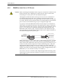
Although some details of the bitstreams used in the AES and S/PDIF standards are different, the audio information is exactly the same. As a result, most audio equipment accepts either standard with no need to convert the bitstream itself; this is the case with the DMA8Plus. However, if you intend to connect sources across different types of digital audio inputs, do not attempt to convert a digital interface type by directly wiring an XLR connector to a BNC or RCA plug. This causes an impedance mismatch and signal reflections, resulting in digital waveform degradation. This may appear to work, but the results are unreliable and dropouts occur.
For conversion between the AES‐3id and S/PDIF formats, you can use high‐quality RCA‐to‐BNC adapters because the cable and impedance are both the same (75Ω).
For conversion between the AES/EBU and AES‐3id or AES/EBU and S/PDIF formats, a simple and economical method uses inline transformers. These devices perform the necessary impedance and balanced/unbalanced conversion. Table 2‐1 shows some examples of suitable adapters. The unbalanced connector in these examples is BNC. 8
Dolby® DMA8Plus Digital Media Adapter Installation and User’s Manual
Connections
You can add BNC‐to‐RCA adapters for connecting to consumer S/PDIF connections. The following units use passive circuitry.
Table 2-1
Examples of Available Balanced/Unbalanced Adapters
Neutrik®
Adapter Type
Canare®
XLR female 110Ω in to BNC female 75Ω out
NA‐BF
BCJ‐XJ‐TRA
BNC female 75Ω in to male XLR 110Ω out
NA‐BM
BCJ‐XP‐TRA
Higher‐priced units incorporating active circuitry are also available. These offer additional features like multiple inputs, inputs for Toslink digital connections, and multiple outputs.
2.3
Connections
For connecting the DMA8Plus to your cinema processor, refer to Wiring Diagrams on page 11. Use the appropriate diagram for your cinema processor model. For proper operation in locations where there is considerable RF or other interference field, strictly adhere to the cable types, lengths, and pin assignments. Shields must connect only to the chassis and should not be paralleled with the negative side of inputs or outputs.
Pinout information for each connector is listed in Rear‐Panel Connector Descriptions and Types on page 36.
2.4
Fuse Information
Warning:
To reduce the risk of fire, replace fuses only with the same type and rating.
The DMA8Plus uses a universal‐switching power supply that handles the full range of nominal mains voltages between 100 and 240 VAC, and any frequency between 50 and 60 Hz. If a power supply fuse blows, do not attempt to replace it. In such a case, please contact Dolby Laboratories for a replacement power supply.
There are two fuses on the Cat. No. 758 board, which are user serviceable, as described in Checking the Two User‐Serviceable Fuses on page 10.
Dolby® DMA8Plus Digital Media Adapter Installation and User’s Manual
9
Installation and Maintenance
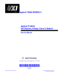
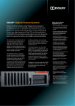
2.4.1
Checking the Two User-Serviceable Fuses
The fuse rating for the user‐serviceable fuses is:
T 1A L (time‐lag, 3.15 amp, 250 V, 20 mm, slow blowing) for all operating voltages.
Warning:
Before performing the following steps, be sure to disconnect the DMA8Plus power cable from the power source.
1. Open the DMA8Plus lid.
2. Remove the fuse cover, which covers the fuses.
3. Remove the two fuses from their slots, check each of them, and replace, if required.
4. Replace the fuse cover.
Figure 2‐1
Figure 2-1
10
Checking the User-Serviceable Fuses
Dolby® DMA8Plus Digital Media Adapter Installation and User’s Manual
Mains Power Wiring
2.5
Mains Power Wiring
In some countries the primary mains cable may not have a connector fitted. These nonterminated leads must be properly wired to an approved mains connector in accordance with the following international code:
•
Brown wire: Live or hot
•
Blue wire: Neutral
•
Green wire: Mains ground
Warning:
2.6
If you are uncertain about the wiring of your AC mains outlet then do not use it. Consult a qualified electrician.
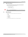
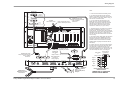
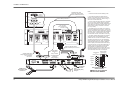
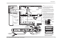
Wiring Diagrams
This section contains connection diagrams for these cinema processors. •
CP650
•
CP500
•
CP65/DA20
•
CP55/DA20
•
CP45/DA20
•
CP200/DA20
Choose the appropriate diagram based on your installed equipment. Dolby® DMA8Plus Digital Media Adapter Installation and User’s Manual
11
Installation and Maintenance
Notes:
C
UL
O
AUTOMATION
US
CP650
Digital Cinema Processor
Wootton Bassett U.K.
San Francisco U.S.
LISTED
PROFESSIONAL AUDIO
EQUIPMENT
4J06
MUTE
U2
NONSYNC
U1
11
10
13
SERIAL DATA (RS-232)
READER 1
01
04
05
L
L+
C
C+
R
R+
Ls
Ls +
Rs
Rs +
SW
SW +
IN
N/C
H/I OUTPUT
~ 50 - 60 Hz 120 W
100 - 240 Vac
This device complies with Part 15 of the FCC Rules.
Operation is subject to the following two conditions: (1) this
device may not cause harmful interference, and (2) this
device must accept any interference received, including
interference that may cause undesired operation.
FUSE T 6.3A L
This Class A digital apparatus complies with Canadian ICES003.
14
L
R
NONSYNC IN 2
R
L
OPTION CARD I/O
WARNING
17
20
OPTICAL IN 1
This equipment must be
earthed/grounded.
R
R
6-CH AUDIO INPUT
23 24 25
(External Digital Processor)
MAIN AUDIO OUTPUT
3. For two-conductor with shield wiring, use
Belden 8451 two-conductor shielded cable or
equivalent: tinned copper, twisted pair, 22 AWG
stranded tinned copper drain wire, aluminumpolyester shield, 100 percent shield coverage,
conductor to conductor (111 pF per meter).
Risk of electric shock.
Do not open.
No user serviceable parts
inside. Refer all service
to qualified personnel.
13
1
CAUTION
MS1
P1
P1/ P2
P2
MS2
NONSYNC IN 1
+
DATA
To reduce the risk of fire
replace only with same
type and rating
250V time-lag fuse.
2. Use earthed (grounded) conduit wherever
possible. Avoid routing signal wiring near electric
motors, rectifiers, power wiring, dimmer wiring, or
other sources of electrical noise.
MOTOR START
Dolby Digital
READER 2
FADER
1. Follow all local electrical and building codes.
ETHERNET
1
REMOTES AND AUD. FADER
REMOTE
MIC. INPUT
L
L
OPTICAL IN 2
5 mm x 20 mm
From
Automation
4. All shields must be connected to the chassis of
the CP650 or DMA8Plus rather than to circuit
(audio) ground. This achieves the RF interference
immunity required by the FCC and European EMC
standards. For D-connectors, a metal housing
must be used and the shields must be connected
to the housing.
Shielded Audio Cable
Dolby Part Number 83528
Part of CDMA/D
See Note 5.
Shielded
Automation Cable F-M-F
Dolby Part Number 83457
Part of CDMA/D
See Note 5.
Digital Media
Push Button
or
Relay Contacts
5. The Shielded Audio and Automation Cables are
included in the CDMA/D cable set.
{
Push Button
or
Relay Contacts
(See Digital Media
Automation
Wiring Diagram)
DIGITAL MEDIA
AUTOMATION
5
9
Digital 4
5
8
Digital 3
5
4
1
6
DMA8Plus
Digital 2
5
3
Film
5
2
Digital 1
5
1
Digital Media Adapter
TO CP CONTROL
4xAES IN
1xAES
1xAES
OPTICAL
AUDIO OUT TO CP
DIGITAL MEDIA
AUTOMATION
AUDIO / VIDEO APPARATUS
19NJ
~ 50–60Hz 15W
100–240 Vac
Dolby, Pro Logic and the double-D symbol
are registered trademarks of Dolby Laboratories.
ACT
TO DA CONTROL
DIGITAL 1 IN
DIGITAL 2 IN
DIGITAL 3 IN
DIGITAL 4 IN
RS-232
LINK
10BASE-T
ANALOG AUDIO IN
F91805G_2.CDR
Auditorium
Network
4xAES Source
Eight-Channel PCM
from Server
{
PCM
Dolby Digital (AC-3)
Dolby E
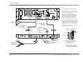
DIGITAL MEDIA AUTOMATION
WIRING DIAGRAM
DMA8PLUS TO CP650
INSTALLATION WIRING
12
Dolby® DMA8Plus Digital Media Adapter Installation and User’s Manual
Wiring Diagrams
Notes:
READER 1
ANALOG ACC. / MAG.
DIGITAL ACC.
READER 2
(Accessory I/O Only)
1. Follow all local electrical and building codes.
OPTICAL 1
R+
R–
MIC. INPUT
RTA
PA
PA
N/C
OPTICAL 2
MUX PWR
MUX GND
MUX DATA
CAUTION
To reduce the risk of fire
replace only with same
type and rating
250V time-lag fuse.
1
2
3
4
5
6
7
8
FUSE T 2A
5mm x 20mm
100 - 240 Vac 50 - 60 Hz 120 W
MODEL CP500
15-24V AC/DC IN
DATA
(External Digital Processor)
VREF
RTN
N/C
FADER
HF
SERIAL DATA
L
BYPASS PWR / REMOTES
MOTOR START
1 2
R
Ls
Rs SW HI
Ms
3. For two-conductor with shield wiring, use
Belden 8451 two-conductor shielded cable or
equivalent: tinned copper, twisted pair, 22 AWG
stranded tinned copper drain wire, aluminumpolyester shield, 100 percent shield coverage,
conductor to conductor (111 pF per meter).
REMOTE
NONSYNC 1
R
L
6 CHANNEL INPUT
AUTOMATION
2. Use earthed (grounded) conduit wherever
possible. Avoid routing signal wiring near electric
motors, rectifiers, power wiring, dimmer wiring, or
other sources of electrical noise.
L–
L+
L
NONSYNC 2
L
R
X-OVER OUT
R
C
Ls
BASS
4. All shields must be connected to the chassis of
the CP500 or DMA8Plus rather than to circuit
(audio) ground. This achieves the RF interference
immunity required by the FCC and European EMC
standards. For D-connectors, a metal housing
must be used and the shields must be connected
to the housing.
Rs
5 6 7 8
Shielded Audio Cable
Dolby Part Number 83528
Part of CDMA/D
See Note 5.
From
Automation
Shielded
Automation Cable F-M-F
Dolby Part Number 83457
Part of CDMA/D
See Note 5.
Digital Media
Push Button
or
Relay Contacts
5. The Shielded Audio and Automation Cables are
included in the CDMA/D cable set.
{
Push Button
or
Relay Contacts
(See Digital Media
Automation
Wiring Diagram)
4xAES IN
1xAES
1xAES
OPTICAL
AUDIO OUT TO CP
DIGITAL MEDIA
AUTOMATION
AUDIO / VIDEO APPARATUS
19NJ
~ 50–60Hz 15W
100–240 Vac
Dolby, Pro Logic and the double-D symbol
are registered trademarks of Dolby Laboratories.
ACT
TO DA CONTROL
DIGITAL 1 IN
DIGITAL 2 IN
DIGITAL 3 IN
DIGITAL 4 IN
RS-232
LINK
10BASE-T
Auditorium
Network
{
9
5
8
Digital 3
5
4
Digital 2
5
3
1
6
ANALOG AUDIO IN
F91805A_2.CDR
4xAES Source
Eight-Channel PCM
from Server
5
Digital 4
DMA8Plus
Digital Media Adapter
TO CP CONTROL
DIGITAL MEDIA
AUTOMATION
PCM
Dolby Digital (AC-3)
Dolby E
Film
5
2
Digital 1
5
1
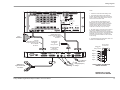
DIGITAL MEDIA AUTOMATION
WIRING DIAGRAM
DMA8PLUS TO CP500
INSTALLATION WIRING
Dolby® DMA8Plus Digital Media Adapter Installation and User’s Manual
13
Installation and Maintenance
Notes:
1. Follow all local electrical and building codes.
MODEL DA20
2. Use earthed (grounded) conduit wherever
possible. Avoid routing signal wiring near electric
motors, rectifiers, power wiring, dimmer wiring or
other sources of electrical noise.
DIGITAL FILM
SOUND PROCESSOR
Audio Out
to CP
WARNING
J8
To reduce the risk of fire
or electric shock do not
expose this equipment to
rain or moisture.
No user serviceable parts
inside. Refer all service
to qualified personnel.
Audio In J7
from CP
Dolby Part Number
83135 (Part of CDA/65)
See Note 5.
Motor
J9 Start
Serial J3
Data
Dolby and the double-D symbol are trademarks of Dolby Laboratories Licensing Corporation.
U.S. and worldwide patents pending.
3. For two-conductor with shield wiring, use
Belden 8451 two-conductor shielded cable or
equivalent: tinned copper, twisted pair, 22 AWG
stranded tinned copper drain wire, aluminumpolyester shield, 100 percent shield coverage,
conductor to conductor (111 pF per meter).
Shielded Audio Cable
Dolby Part Number 83528
Part of CDMA/A
See Note 5.
CP Sense/
J6
Control
4. All shields must be connected to the chassis of
the DA20 or DMA8Plus rather than to circuit
(audio) ground. This achieves the RF interference
immunity required by the FCC and European EMC
standards. For D-connectors, a metal housing
must be used and the shields must be connected
to the housing.
MODEL CP65
mag format
NO NR
NR
J24
TB2
non-sync in
TB1 L R
automation inputs
S0 S1 S2 S3 S4 S5 S6 S7 C/
O
pre-amp
Lt Rt
auto c/o
remote fader
M C/ O
C E B A D
U
T
E
5. Re-attach existing cables (Dolby Part Numbers
83134 and 83135) to the DMA8Plus as shown
(cables are included in CDA/65 cable set). The
Shielded Audio and Data Cables are included in
CDMA/A cable set (Dolby Part Numbers 83442
and 83528).
To Power Amps
H/I
L C
R
From mpu
Ls Rs SW
L C
MAG
HEADER
#2
Format 42
R S
From Digital
L C R Ls Rs SW
Le Re
Proj 1
L
Proj 2
L
R
TB7
TB4
TB3
6. Caution: Be sure to ground the negative side of
all audio channels. The original CP audio cables
were designed for unbalanced audio. Not all
grounds are connected to the negative side of the
associated DMA8Plus channel. Insert the Cat. No.
757 audio adapter as shown on the diagram.
R
Proj
2
Dolby Part Number 83134
(Part of CDA/65) See Note 5.
Shielded Data Cable
Dolby Part Number 83442
Part of CDMA/A
See Note 5.
DIGITAL MEDIA
AUTOMATION
{
Digital Media
Push Button
or
Relay Contacts
Push Button
or
Relay Contacts
(See Digital Media
Automation
Wiring Diagram)
Digital 4
Cat. No. 757
DMA8Plus
4xAES IN
1xAES
1xAES
OPTICAL
AUDIO OUT TO CP
DIGITAL MEDIA
AUTOMATION
9
1
6
5
8
Digital 3
5
4
Digital 2
5
3
Digital Media Adapter
TO CP CONTROL
5
Film
5
2
Digital 1
5
1
AUDIO / VIDEO APPARATUS
19NJ
~ 50–60Hz 15W
100–240 Vac
Dolby, Pro Logic and the double-D symbol
are registered trademarks of Dolby Laboratories.
ACT
TO DA CONTROL
DIGITAL 1 IN
DIGITAL 2 IN
DIGITAL 3 IN
DIGITAL 4 IN
RS-232
LINK
10BASE-T
ANALOG AUDIO IN
F91805B_2.CDR
4xAES Source
Eight-Channel PCM
from Server
14
{
Auditorium
Network
PCM
Dolby Digital (AC-3)
Dolby E
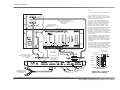
DIGITAL MEDIA AUTOMATION
WIRING DIAGRAM
DMA8PLUS TO CP65/DA20
INSTALLATION WIRING
Dolby® DMA8Plus Digital Media Adapter Installation and User’s Manual
I
Wiring Diagrams
Notes:
MODEL DA20
DIGITAL FILM
SOUND PROCESSOR
1. Follow all local electrical and building codes.
Audio Out
J8
to CP
WARNING
To reduce the risk of fire
or electric shock do not
expose this equipment to
rain or moisture.
No user serviceable parts
inside. Refer all service
to qualified personnel.
Audio In J7
from CP
CP Sense/
J6
Control
To DMA8
AUDIO OUT TO CP
Dolby Part Number 83132
(Part of CDA/55) See Note 5.
Motor
J9 Start
Serial J3
Data
Shielded Audio Cable
Dolby Part Number 83528
Part of CDMA/A
See Note 5.
ID1
ID0
ID2
ID6
ID5
ID4
ID3
ID7
gnd
Dolby and the double-D symbol are trademarks of Dolby Laboratories Licensing Corporation.
U.S. and worldwide patents pending.
2. Use earthed (grounded) conduit wherever
possible. Avoid routing signal wiring near electric
motors, rectifiers, power wiring, dimmer wiring, or
other sources of electrical noise.
3. For two-conductor with shield wiring, use
Belden 8451 two-conductor shielded cable or
equivalent: tinned copper, twisted pair, 22 AWG
stranded tinned copper drain wire, aluminumpolyester shield, 100 percent shield coverage,
conductor to conductor (111 pF per meter).
remote fader
indicator
CAT
242
28 FF
TB1
L
C R S
mute
C R S
CAT.NO.
241
16
T
gnd
S9
non sync
aux
L
auto c/o
C/O
R
CAT.NO.
64B
4. All shields must be connected to the chassis of
the DA20 or DMA8Plus rather than to circuit
(audio) ground. This achieves the RF interference
immunity required by the FCC and European EMC
standards. For D-connectors, a metal housing
must be used and the shields must be connected
to the housing.
TB2
TB1
from mag
CAT.NO.
64B
auto fader
C E B A
CAT.NO.
64B
bypass preamp
D FI BC
CAT.NO.
150
Lt Rt
CAT.NO.
85
CAT.NO.
222
CAT.NO.
240
spare
S8
SO
S1
S2
5. Re-attach existing cables (Dolby Part Numbers
83132 and 83133) to the DMA8Plus as shown.
(Cables are included in CDA/55 cable set.) The
Shielded Audio and Data Cables are included in
CDMA/A cable set (Dolby Part Numbers 83442
and 83528).
S3
S4
Voltage select
D
S5
S6
R
S7
1
TB2
1
J7
J8
A
1 2
J10
J9
bypass
A indicator
J11
J14
J13
J12
Proj 1
L
to power amps
L
C
R
S B/E
test
J15
J16
Proj 2
L
R
R
6. Caution: Be sure to ground the negative side of
all audio channels. The original CP audio cables
were designed for unbalanced audio. Not all
grounds are connected to the negative side of the
associated DMA8Plus channel. Insert the Cat. No.
757 audio adapter as shown on the diagram.
TB4
TB3
J18
MODEL CP55
Dolby Part Number 83133
(Part of CDA/55) See Note 5.
Digital Media
Push Button
or
Relay Contacts
Shielded Data Cable
Dolby Part Number 83442
Part of CDMA/A
See Note 5.
{
Push Button
or
Relay Contacts
(See Digital Media
Automation
Wiring Diagram)
Cat. No. 757
Digital 4
DMA8Plus
Digital Media Adapter
TO CP CONTROL
4xAES IN
1xAES
1xAES
OPTICAL
~ 50–60Hz 15W
100–240 Vac
Dolby, Pro Logic and the double-D symbol
are registered trademarks of Dolby Laboratories.
ACT
TO DA CONTROL
DIGITAL 1 IN
DIGITAL 2 IN
DIGITAL 3 IN
DIGITAL 4 IN
RS-232
Dolby® DMA8Plus Digital Media Adapter Installation and User’s Manual
9
1
6
5
8
5
4
Digital 2
5
3
Film
5
2
Digital 1
5
1
LINK
10BASE-T
ANALOG AUDIO IN
F91805D_2.CDR
4xAES Source
Eight-Channel PCM
from Server
5
Digital 3
AUDIO OUT TO CP
DIGITAL MEDIA
AUTOMATION
AUDIO / VIDEO APPARATUS
19NJ
DIGITAL MEDIA
AUTOMATION
{
Auditorium
Network
PCM
Dolby Digital (AC-3)
Dolby E
DIGITAL MEDIA AUTOMATION
WIRING DIAGRAM
DMA8PLUS TO CP55/DA20
INSTALLATION WIRING
15
Installation and Maintenance
MODEL DA20
Shielded Audio Cable
Dolby Part Number 83528
Part of CDMA/A See Note 5.
DIGITAL FILM
SOUND PROCESSOR
Audio Out
J8
to CP
WARNING
To reduce the risk of fire
or electric shock do not
expose this equipment to
rain or moisture.
No user serviceable parts
inside. Refer all service
to qualified personnel.
Audio In J7
from CP
Dolby Part Number 83135
(Part of CDA/45) See Note 5.
3. For two-conductor with shield wiring, use Belden
8451 two-conductor shielded cable or equivalent:
tinned copper, twisted pair, 22 AWG stranded tinned
copper drain wire, aluminum-polyester shield, 100
percent shield coverage, conductor to conductor
(111 pF per meter).
Motor
J9 Start
Dolby and the double-D symbol are trademarks of Dolby Laboratories Licensing Corporation.
U.S. and worldwide patents pending.
Cat. No. 545A
(Part of CDA/45)
See Note 5.
MODEL CP45
J9
BOOTH MONITOR OUTPUT
J10
J11
LF
J1
HF
LF
HF
J2
LF
HF
LS
RS
TO CPU P10
SW
J7
PROJECTOR 1
J4
J5
J6
1 2 3 4 5 6 7 8
1 2 3 4 5 6 7 8
1 2 3 4 5 6 7 8
J3
1 2 3 4 5 6 7 8
BYPASS
NORMAL
LF
HF
FULL
RANGE
LEFT
LF
1 2 3 4 5 6 7 8
HF
FULL
RANGE
CENTER
*
LF
HF
Ls
Rs
SW
R
L
NON
SYNC 1
NON-SYNC 2
AUXILIARY
5. Re-attach existing cables (Dolby Part Numbers
83306 and 83135) to the DMA8Plus as shown.
(Cables and Cat. No. 545A are included in CDA/45
upgrade kit. All existing Cat. No. 545 assemblies
must be upgraded to Cat. No. 545A. The Shielded
Audio and Data Cables are included in CDMA/A
cable set (Dolby Part Numbers 83442 and 83528).
L+
L–
J8
PROJECTOR 2
COM
P2
P1
4
L
C
R
COM
LS
RS
SW
COM
2 3
HEARING
IMPAIRED
R+
R–
1
4. All shields must be connected to the chassis of
the DA20 or DMA8Plus rather than to circuit (audio)
ground. This achieves the RF interference immunity
required by the FCC and European EMC standards.
For D-connectors, a metal housing must be used
and the shields must be connected to the housing.
CONTROL
LOGIC TO
DIGITAL
PROCESSOR
J12
TO AUTOMATION
RANGE
PROJECTOR
MIC CHANGEOVER
INPUTS
OUTPUTS
1 2
3 4 5
6 7
8
Dolby Part Number 83306
(Part of CDA/45) See Note 5 & 6.
Digital Media
Push Button
or
Relay Contacts
Shielded Data Cable
Dolby Part Number 83442
Part of CDMA/A
See Note 5.
1. Follow all local electrical and building codes.
2. Use earthed (grounded) conduit wherever
possible. Avoid routing signal wiring near electric
motors, rectifiers, power wiring, dimmer wiring, or
other sources of electrical noise.
CP Sense/
J6
Control
Serial J3
Data
Notes:
{
6. Caution: Be sure to ground the negative side of
all audio channels. The original CP audio cables
were designed for unbalanced audio. Not all
grounds are connected to the negative side of the
associated DMA8Plus channel. Insert the Cat. No.
757 audio adapter as shown on the diagram.
DIGITAL MEDIA
AUTOMATION
Push Button
5
1
or
Relay Contacts
9
6
(See Digital Media
Automation
Wiring Diagram)
Cat. No. 757
Digital 4
Digital 3
5
4
Digital 2
5
3
DMA8Plus
Digital Media Adapter
TO CP CONTROL
4xAES IN
1xAES
1xAES
OPTICAL
AUDIO OUT TO CP
DIGITAL MEDIA
AUTOMATION
AUDIO / VIDEO APPARATUS
19NJ
~
100–240 Vac
50–60Hz 15W
Dolby, Pro Logic and the double-D symbol
are registered trademarks of Dolby Laboratories.
ACT
TO DA CONTROL
DIGITAL 1 IN
DIGITAL 2 IN
DIGITAL 3 IN
DIGITAL 4 IN
RS-232
LINK
10BASE-T
ANALOG AUDIO IN
F91805C_2.CDR
4xAES Source
Eight-Channel PCM
from Server
16
{
Auditorium
Network
PCM
Dolby Digital (AC-3)
Dolby E
5
8
Film
5
2
Digital 1
5
1
DIGITAL MEDIA AUTOMATION
WIRING DIAGRAM
DMA8PLUS TO CP45/DA20
INSTALLATION WIRING
Dolby® DMA8Plus Digital Media Adapter Installation and User’s Manual
Wiring Diagrams
Notes:
1. Follow all local electrical and building codes.
JM2
MODEL DA20
DIGITAL FILM
SOUND PROCESSOR
Audio Out
J8
to CP
Audio In J7
from CP
JM3
(12)
BS1
(1)
BS2
(1)
JM5
SP2-14
No user serviceable parts
inside. Refer all service
to qualified personnel.
SK13
SP2
16
CAT.150
T
CAT.160
23
RL2
3. For two-conductor with shield wiring, use Belden
8451 two-conductor shielded cable or equivalent:
tinned copper, twisted pair, 22 AWG stranded tinned
copper drain wire, aluminum-polyester shield, 100
percent shield coverage, conductor to conductor
(111 pF per meter).
SK13-B21
J6
Serial J3
Data
2. Use earthed (grounded) conduit wherever
possible. Avoid routing signal wiring near electric
motors, rectifiers, power wiring, dimmer wiring, or
other sources of electrical noise.
JM4
RL3
CP Sense/
Control
(1)
(12)
WARNING
To reduce the risk of fire
or electric shock do not
expose this equipment to
rain or moisture.
Motor
J9 Start
CP200 Processor Unit
1
Dolby and the double-D symbol are trademarks of Dolby Laboratories Licensing Corporation.
U.S. and worldwide patents pending.
1
A
A
1
B
JM10
SK13-B1
Dolby Part Number
83136
Part of CDA/200
.
JM8
JM9
(1)
JM11
Shielded Audio Cable
Dolby Part Number
83528
Part of CDMA/A
See Note 5.
4. All shields must be connected to the chassis of
the DA20 or DMA8Plus rather than to circuit (audio)
ground. This achieves the RF interference immunity
required by the FCC and European EMC standards.
For D-connectors, a metal housing must be used
and the shields must be connected to the housing.
JM21
JM24
JM22
JM20
5. Re-attach existing cables (Dolby Part No’s 83137
and 83138) to the DMA8Plus as shown. (Cables
included in CDA/200 cable set.) The Shielded Audio
Cable is included in the CDMA/A cable set.
JM30
JM23
JM25
Dolby Part Number
83137
Part of CDA/200
See Note 5.
Push Button or
Relay Contacts
JM26
BS24
BS23
(1)
MUTE LED
AUTO MUTE
PROJ 3 CONTROL
PJ21
PROJ 2 CONTROL
EMERGENCY C/O
PJ22
PROJ 1
Dolby Part Number
83138
Part of CDA/200
See Note 5.
PJ23
PROJ 2
PJ24
PROJ 1 CONTROL
CP200 Control Unit
(12)
(1)
BS22
(12)
5
1
9
Digital 4
5
8
Digital 3
5
4
Digital 2
5
3
Film
5
2
Digital 1
5
1
6
DIGITAL MEDIA
AUTOMATION
CP200 PU
6
7
SK13-B21
GND
Digital
Subwoofer
Control
DIGITAL MEDIA AUTOMATION
WIRING DIAGRAM
{
Digital Media
Push Button or
Relay Contacts
(See Digital Media
Automation Wiring Diagram)
CP200 PU
Audio
Cat. No. 757
Control
DA20
DMA8Plus
Digital Media Adapter
TO CP CONTROL
4xAES IN
1xAES
1xAES
OPTICAL
AUDIO OUT TO CP
DIGITAL MEDIA
AUTOMATION
DMA8PLUS
AUDIO / VIDEO APPARATUS
19NJ
~ 50–60Hz 15W
100–240 Vac
Dolby, Pro Logic and the double-D symbol
are registered trademarks of Dolby Laboratories.
ACT
TO DA CONTROL
DIGITAL 1 IN
DIGITAL 2 IN
DIGITAL 3 IN
DIGITAL 4 IN
RS-232
LINK
10BASE-T
ANALOG AUDIO IN
F91805E_2.CDR
CP200 CU
4xAES Source
Eight-Channel PCM
from Server
Dolby® DMA8Plus Digital Media Adapter Installation and User’s Manual
{
Auditorium
Network
PCM
Dolby Digital (AC-3)
Dolby E
SIGNAL FLOW DIAGRAM
DMA8PLUS TO CP200/DA20
INSTALLATION WIRING
17
Chapter 3
Setting up the DMA8Plus
3.1
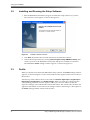
DMA8Plus Setup Software
The setup software is required to complete the DMA8Plus installation and perform other functions. You begin by installing the setup software on a PC running Microsoft® Windows® XP Service Pack 2 or later. When the installation is completed, you launch the setup software, and then connect your PC to the DMA8Plus using a USB cable (as described in Installing and Running the Setup Software on page 20) to perform the following functions:
•
Select the model number of the cinema processor connected to the DMA8Plus for DA/CP control
•
Enter the network settings
•
Select the PCM input‐channel routing
•
Set the Global delay for each digital input
•
Set the 2Ch Decode Mode (Auto, Pro Logic®, Pro Logic II, or Discrete L/R) for PCM, Dolby® Digital, and Dolby E
•
Enable or disable Silent Switch mode
•
Enable or disable Dialog Normalization for Dolby Digital bitstreams
•
Set the Surround Delay
•
Select the Pro Logic subwoofer filter
•
Select the Power-on Mode
•
Select the ‘To CP Control’ Pin Assignments
In addition, the setup software displays the following information:
•
Sample Rate and Data Rate (when available)
•
Dialnorm and Channel Mode metadata information (when available)
•
Signal‐level monitoring level meters
•
Current input selection
•
Audio format (PCM, Dolby Digital, Dolby E, or Aux)
•
Decode mode (Pro Logic, Pro Logic II, or Discrete) •
Version numbers for the DMA8Plus firmware and setup software Dolby® DMA8Plus Digital Media Adapter Installation and User’s Manual
19
Setting up the DMA8Plus
3.2
Installing and Running the Setup Software
1.
Run the DMA8Plus installation program to install the setup software on your PC.
The welcome screen appears, as shown in Figure 3‐1.
Figure 3-1
Installation Welcome Screen
2. Click Next, then follow the onscreen instructions to install the software.
3. Launch the setup software by selecting Start>Programs>Dolby>DMA8Plus Setup, then connect your PC to the DMA8Plus front‐panel USB port to establish a connection. The DMA8Plus Profile settings window appears, as shown in Figure 3‐2.
3.3
Profile
When you launch and connect the DMA8Plus setup software, the Profile settings window appears, as shown in Figure 3‐2. The virtual status monitor appears in the lower section of the window. Near the top of the window, there are also tabs for Network, Digital Input 1, Digital Input 2, Digital Input 3, Digital Input 4, and Global Settings. When you click any of these tabs, the corresponding parameter window appears where you can enter and/or modify the respective settings, as described in the sections that follow. The virtual status monitor also appears at the bottom of each of these tab settings windows. Following is a description of the Profile settings and the virtual status monitor.
20
Dolby® DMA8Plus Digital Media Adapter Installation and User’s Manual
Profile
Figure 3-2
3.3.1
Profile Settings Window
Profile Settings
Selecting this tab displays the Profile settings window. In this window, you can enter the corresponding information for your system. This information defines the Theatre Profile for the local auditorium. In addition, Input Descriptions appears for each digital input. You can edit each description and enter the desired information.
3.3.2
Virtual Status Monitor
The virtual status monitor provides a user‐friendly interface that is similar to the DMA8Plus front panel. Its eight‐channel signal‐presence meter monitors the DMA8Plus analog output (before the bypass relays). Five virtual buttons represent the digital 1, digital
2, digital 3, digital 4, and film input selections. When you click any of these buttons, the associated input is activated. Each of the digital input buttons has an associated virtual LED, representing a valid clock presence. In addition, four virtual LEDs represent format decoding, one each for PCM, Dolby Digital, Dolby E, and Aux (for future use). Three more virtual LEDs represent the decode mode, one each for Pro Logic II, Pro Logic, and Discrete. Parameter indicators display the Sample Rate, Data Rate, Dialnorm, and Channel Mode
(when available).
Dolby® DMA8Plus Digital Media Adapter Installation and User’s Manual
21
Setting up the DMA8Plus
3.4
Network
Selecting this tab displays the DMA8Plus Ethernet Settings window, as shown in Figure 3‐3. In this window, you can configure the DMA8Plus network settings. If you change the network settings, two buttons are highlighted below your settings: Discard
Changes and Apply Changes. Clicking one of these buttons performs the respective action. The default entries are set for a Dolby Digital Cinema system. Following is list of these default entries:
•
Host Name: DMA8Plus
•
DHCP: Disable
•
IP Address: 192.168.x.131 (x = auditorium number)
•
Subnet Mask: 255.255.255.128
•
Default Gateway: 192.168.x.129 (x = auditorium number)
Figure 3‐1
Figure 3-3
22
Ethernet Settings Window
Dolby® DMA8Plus Digital Media Adapter Installation and User’s Manual
Digital Inputs 1, 2, 3, and 4
3.5
Digital Inputs 1, 2, 3, and 4
Selecting any of these tabs displays the corresponding digital input window. The examples in Figure 3‐4 and Figure 3‐5 show the Digital Input 1 and Digital Input 2 windows. The same setting options are provided in each digital input window, except for the PCM Channel
Assignment, which appears only in the Digital Input 1 window. Following is a description of each of these settings.
Figure 3‐2
Figure 3-4
Digital Input 1 Window
Dolby® DMA8Plus Digital Media Adapter Installation and User’s Manual
23
Setting up the DMA8Plus
Figure 3‐3
Figure 3-5
3.5.1
Digital Input 2 Window
Global Delay
Specifies an audio delay (in addition to the DMA8Plus decoding delay of approximately 7 ms for 4xAES PCM). This function synchronizes the audio with the video that is required for digital cinema projectors, which add a video processing delay. Use the up and down arrows to set the Global delay between 0 and 250 ms. You can specify a different Global delay for digital 1, digital 2, digital 3, and digital 4. Systems that use an external video scaler may add another decoding delay.
3.5.2
PCM Settings
Following is a description of the PCM settings.
PCM Channel Assignment (Digital Input 1 Only)
The analog audio output channels (L, R, C, LFE, Ls, Rs) are always fixed and hardwired to a cinema processor. However, when a PCM bitstream input‐channel mapping is not a default SMPTE configuration (L/R, C/LFE, Ls/Rs), you must reassign the input channels to match the hard wired audio outputs. For channel reassignment, the surround delay and the LFE filter are always tied at the output.
24
Dolby® DMA8Plus Digital Media Adapter Installation and User’s Manual
Digital Inputs 1, 2, 3, and 4
To reassign the input channels, use the drop‐down menu for each of the AES channel inputs or click one of the three preset buttons (L/R C/Sw/ Ls/Rs, L/C R/Ls, Rs/Sw, or L/Ls C/Rs R/Sw). To activate your changes, click the Apply changes button. To cancel your changes, click the Discard changes button.
2Ch Decode Mode
These options apply only to a two‐channel input stream. There are three options: Pro Logic,
Pro Logic II, and Discrete L/R. Note:
For Dolby Digital Cinema multichannel PCM, you must use the Discrete L/R option. Processing Mode
Minimum Latency
When selected, this default mode provides the quickest audio processing (approximately 7 ms) for PCM audio.
Silent Switch
When selected, this mode constantly checks for transitions between PCM and coded audio, and switches between the two silently. This mode adds a 40 ms latency to the audio processing (for a total latency of approximately 47 ms).
Mute
When selected, this mode mutes the audio when PCM is detected.
3.5.3
Dolby Digital Settings
Following is a description of the Dolby Digital settings,
2Ch Decode Mode
For two‐channel configurations, there are four options: Auto, Pro Logic, Pro Logic II, and Discrete L/R. The audio decode mode follows the surrounds metadata parameter that is embedded within the bitstream. Alternatively, you can enable Pro Logic or Pro Logic II decoding, which overrides the presence or absence of the surrounds metadata in two‐channel bitstreams. The Discrete L/R mode sends the audio only to the Left and Right channels.
Dialog Normalization
When enabled (Enable), this option sets the decoder level shift according to the encoded metadata embedded in a Dolby Digital (AC‐3) bitstream. Metadata is available on most DVDs, terrestrial and satellite broadcast signals, and other Dolby Digital sources. The default is Disable.
Dolby® DMA8Plus Digital Media Adapter Installation and User’s Manual
25
Setting up the DMA8Plus
3.5.4
Dolby E Settings
Following is a description of the Dolby E settings.
2Ch Decode Mode
Same functionality as for Dolby Digital, as described previously.
Dialog Normalization
Same functionality as for Dolby Digital, as described previously.
Program Select
You can select one of four possible programs to receive a Dolby E bitstream: P1, P2, P3, or P4. The default is P1.
3.6
Global Settings
Selecting this tab displays the Global Settings window, as shown in Figure 3‐6. Following is a description of each of these settings.
Figure 3‐4
Figure 3-6
26
Global Settings Window
Dolby® DMA8Plus Digital Media Adapter Installation and User’s Manual
Global Settings
3.6.1
CP Settings
Following is a description of the cinema processor (CP) settings.
Cinema Processor
Selects the cinema processor connected to the DMA8Plus. This parameter affects the ‘To CP
Control’ Pin Assignments. If you are not using a Dolby processor, select Custom and set the appropriate ‘To CP Control’ Pin Assignments for your setup. ‘To CP Control’ Pin Assignments
The pin assignments for Film and Digital Media correspond to the cinema processor’s nonsync format and six‐channel input format. For default CP formats on control lines 0–7 (pins 1–8) see Table 4‐7. The various DMA8Plus cinema processor Film defaults correspond to each cinema processor’s default nonsync format. Likewise, the Digital Media defaults correspond to each cinema processor’s default six‐channel input format. You can change any of these pins manually to accommodate your setup.
3.6.2
Surround Delay
When the unit receives audio from a digital media source, you need to apply a delay to the Surround channels, so the Center and Surrounds audio reach the listener at the same time. Set the Surround Delay by entering the dimensions of the auditorium and clicking the Calculate button, or use the slider if you know the required delay setting. Note:
3.6.3
If the DMA8Plus is connected to a CP650, the CP650 applies the appropriate digital media surround delay based on its settings (format 11). If the CP650 has been selected as the cinema processor type, the Surround Delay setting in this window is disabled. Use this function to set the digital media surround delay only when connected to other cinema processors.
Pro Logic/Pro Logic II Subwoofer
Selects a subwoofer filter of 50 Hz (default) or 100 Hz for Pro Logic and Pro Logic II decoding. This subwoofer signal is derived from the matrix decoded sum of Left, Center, and Right, which passes through this filter. The main audio outputs bandwidth (L, C, R) is not affected because this subwoofer signal is a reinforcement rather than a bass redirection.
3.6.4
Power-on Mode
Selects the desired DMA8Plus startup mode when the unit is powered on. You can select Last Setting, Film, or any of the digital inputs: digital 1 (4xAES), digital 2 (1xAES),
digital 3 (1xAES), or digital 4 (Optical).
Dolby® DMA8Plus Digital Media Adapter Installation and User’s Manual
27
Setting up the DMA8Plus
3.7
File Menu
You can use the setup software File menu to load and save settings. Following is a description of each of these functions.
3.7.1
Loading Settings
You can load a previously saved .dlb parameter file as follows:
Select Open in the File menu, browse to the desired .dlb file on your PC, and open that file.
Figure 3‐5
Figure 3-7
3.7.2
Selecting Open in the File Menu
Saving Settings
You can save your current settings to a .dlb parameter file as follows:
Select Save in the File menu, browse to the location on your PC where you want to save the file, enter a file name, and click Save. To modify an existing .dlb file and save it under a different name, open the file, then select Save As in the File menu.
Figure 3‐6
Figure 3-8
28
Selecting Save in the File Menu
Dolby® DMA8Plus Digital Media Adapter Installation and User’s Manual
Action Menu
3.8
Action Menu
You can use the setup software Action menu to connect to a local or remote device and update the DMA8Plus firmware, as described in the sections that follow. The Extract Logs and View Log options currently do not function. To extract an event log, see ASCII String Commands on page 42.
Figure 3‐7
Figure 3-9
3.8.1
Action Menu
Connecting to a Local or Remote Device
These options allow you to connect to a DMA8Plus that is connected to your PC (local device) or a DMA8Plus that is connected to an Ethernet network (remote device). If you select Connect to remote device, a prompt for an IP address appears, as shown in Figure 3‐10. Enter the IP address of the remote DMA8Plus and click OK.
Note:
Figure 3‐8
If you are connecting directly to a DMA8Plus, use a crossover cable. If you are connecting to a switch, use a standard Ethernet cable.
Figure 3-10 Connect to Remote DMA8Plus Prompt
3.8.2
Update Software
With setup software version 1.2.5.0 and later, when you select this option, the setup software closes and Dolby Software Update automatically opens and connects. You can then update the DMA8Plus firmware by following the directions in Updating the DMA8Plus Firmware on page 31. When the update is completed, Dolby Software Update closes and the setup software opens and reconnects.
Dolby® DMA8Plus Digital Media Adapter Installation and User’s Manual
29
Setting up the DMA8Plus
3.9
Window Menu
You can use the Window menu to toggle in and out of Expert View mode. In addition, you can turn the Setup (tabs view) and/or Monitor display(s) on or off.
Figure 3‐9
Figure 3-11
Window Menu
Using Expert View
When you select Expert View, all the DMA8Plus parameters and command strings appear, including some parameters not displayed in the tabs view. You can modify each of the parameters that are highlighted in green by double clicking on any of these (or selecting one and pressing <Enter>), and then typing the new parameter entry. For more information, see ASCII String Commands on page 42. To return to the tabs display, select
Expert View again to uncheck it.
Figure 3‐10
Figure 3-12 Expert View Window
30
Dolby® DMA8Plus Digital Media Adapter Installation and User’s Manual
Updating the DMA8Plus Firmware
3.10
Updating the DMA8Plus Firmware
To update the DMA8Plus firmware:
1.
Obtain the latest version of the Dolby Software Update application from Dolby Laboratories and install it on your PC.
2. Obtain the .dlb update file from Dolby Laboratories and copy it to your PC.
3. Connect your PC to the USB port on the DMA8Plus front panel. 4. Select Start>Programs>Dolby>Dolby Software Update to launch the update application.
Figure 3‐11
Figure 3-13 Dolby Software Update Screen
5. Click Browse to find the .dlb update file on your PC, then click Open.
6. Click Update.
After a few seconds, a progress bar displays the status of the update process. When the process is completed, the DMA8Plus automatically reboots with the updated firmware.
Dolby® DMA8Plus Digital Media Adapter Installation and User’s Manual
31
Chapter 4
Technical Reference
4.1
DMA8Plus Specifications
PC Connection
USB port for setup operations and software upgrades
Input Selector Buttons
Digital 1 through 4 source buttons Film source button (pass‐through)
Indicators
Valid LEDs indicate digital input clock presence for each digital input
Format LEDs indicate PCM, Dolby Digital, Dolby E, or Aux (future) processing
Decode mode LEDs indicate Pro Logic II, Pro Logic, or Discrete modes
Output activity LEDs indicate the presence of signals in each output channel
Construction
1‐U rackmount chassis frame
Digital Signal Inputs
All have floating grounds, +10 V peak difference between the DMA8Plus chassis and signal common permitted
Digital 1 In (4xAES)
25‐pin female D‐connector provides four AES/EBU inputs of PCM audio (up to eight channels)
Input impedence: 110 Ω
Digital 2 In (1xAES)
Male BNC connector, unbalanced per AES‐3ID‐1995/SMPTE 276M
Input impedence: 75 Ω Digital 3 In (1xAES)
Male BNC connector, unbalanced per AES‐3ID‐1995/SMPTE 276M
Input impedence: 75 Ω
Dolby® DMA8Plus Digital Media Adapter Installation and User’s Manual
33
Technical Reference
Digital 4 In (Optical)
Optical connector for digital input
Digital Audio Source Formats
PCM: 44.1, 48 and 96 kHz; 16‐, 20‐, 24‐bit Dolby Digital (AC‐3)
Dolby E (23.98, 24, 25, 29.97, 30 fps)
Dolby Pro Logic II
Dolby Surround Pro Logic
Dolby Cinema Processor Compatibility
CP650, CP500, CP200, CP65, CP55, CP45, DA20 Global Delay
Adjustable delay of all channels from 0–250 ms (separate delay for each input)
Surround Channel Delay
Digital media program sources: adjustable from 0–150 ms Power Requirements
100–240 VAC, 50–60 Hz
Analog Audio Input
25‐pin female D‐connector for six‐channel analog output of a Dolby DA20 or other external processor, which is passed through when Film mode is selected or during power off
Analog Audio Output
25‐pin male D‐connector, balanced for connecting to a Dolby cinema processor
L, C, R, Ls, Rs, SW (unassigned channels 7 and 8 pass‐through for CP200) 300 mV reference level
To CP Control
25‐pin male D‐connector for format sensing and control providing a customized interface for each Dolby cinema processor. This input has a floating common, < +10 V peak between the DMA8Plus chassis and common permitted.
To DA Control
25‐pin female D‐connector for format sensing and control providing a customized interface for each Dolby cinema processor. This input has a floating common, < +10 V peak between the DMA8Plus chassis and common permitted.
34
Dolby® DMA8Plus Digital Media Adapter Installation and User’s Manual
DMA8Plus Specifications
RS-232 Serial Port
9‐pin female D‐connector for interfacing with software‐based automation systems by way of ASCII command strings
10BASE-T Ethernet Port
Ethernet port for interfacing with Dolby Digital Cinema systems and ASCII command strings
Digital Media Automation
9‐pin female D‐connector, ground‐switching relay contact closure for each front‐panel button control Relay contacts provided for CP200 subwoofer control (closure upon any digital format selection). This input has a floating common, < +10 V peak between the DMA8Plus chassis and common permitted.
Distortion
<0.005 percent, 4×AES input‐to‐analog output
Dynamic Range
Digital clip to CCIR/ARM weighted noise
Typically greater than 105 dB
Dimensions and Weight
44 × 483 × 342 mm (1.75 × 19 × 13.5 inches)
Net: 4.5 kg (10 lb) Environmental Conditions
Operating: 0°C to 40°C (32°F to 104°F)
Nonoperating (storage): 0°C to 85°C (32°F to 185°F)
Humidity: 20 to 80 percent relative, noncondensing
Regulatory Notices
North America: This unit complies with the limits for a Class A digital device, pursuant to Part 15 of the FCC rules, and Industry Canada ICES‐003 specifications. It is UL Listed for both US and Canada.
Europe: This unit complies with the requirements of Low Voltage Directive 73/23/EEC and EMC Directive 89/336/EEC and carries the CE marking accordingly.
Warranty
One‐year limited, parts and labor
Specifications subject to change without notice
Dolby® DMA8Plus Digital Media Adapter Installation and User’s Manual
35
Technical Reference
4.2
Rear-Panel Connector Descriptions and Types
Table 4-1
Rear-Panel Connector Descriptions and Types
Panel Label
Description
Type
Digital Media Automation
Theatre automation control input (momentary contact), CP200 subwoofer control DB‐9
RS‐232 In
ASCII command string automation control
DB‐9
10BASE‐T Ethernet connector for ASCII command string control, setup software, Dolby Digital Cinema network
RJ45
To DA Control
DA20 cinema processor sense control
DB‐25
To CP Control
Cinema processor automation DB‐25
Analog Audio In
Eight‐channel balanced floating analog input for DB‐25
external processor, such as a Dolby DA20
Audio Out to CP
Eight‐channel balanced floating analog output: DB‐25
L, C, R, Ls, Rs, Sw, 7, 8
4.2.1
Optical
S/PDIF optical, Dolby Digital, PCM, Dolby E
Toslink
4xAES In
4 x AES/EBU input (eight‐channel PCM audio)
DB‐25
1xAES In
Dolby Digital, PCM, Dolby E 2 x BNC
100–240 VAC, 50–60 Hz, 15 W
AC power inlet module with filter IEC
Digital Media Automation Connector
Table 4-2
Digital Media Connector Pinout
Pin
Number
Function
1
Digital 1 mode
Pulse to pin 5 (push button, relay contacts, etc.) 100 ms min.
2
Film mode
Pulse to pin 5 (push button, relay contacts, etc.)
3
Digital 2 mode
Pulse to pin 5 (push button, relay contacts, etc.) 100 ms minimum
4
Digital 3 mode
Pulse to pin 5 (push button, relay contacts, etc.) 100 ms minimum
5
Digital media automation common
Common for pins 1, 2, 3, 4, 8
6
CP200 digital control Return for pin 7
7
CP200 digital control
N/O contact closes (latch) to pin 6 in Digital 1–4 modes
8
Digital 4 mode
Pulse to pin 5 (push button, relay contacts, etc.) 100 ms minimum
9
+5 VDC with respect to pin 5
100 mA maximum current, floating rail
(current limited)
36
Specification
Dolby® DMA8Plus Digital Media Adapter Installation and User’s Manual
Rear-Panel Connector Descriptions and Types
4.2.2
Analog Audio In/Out Connectors
Caution: The DMA8Plus has balanced floating analog inputs and outputs. To achieve a full reference level signal, use both positive (Pos) and negative (Neg) pins for each channel.
Table 4-3
Analog Audio In/Out Connector Pinout
Analog Audio In
Analog Audio Out
Signal Name
(From DA20)
Signal Name
(To CP)
Pin Number
Pin Number
1
Left Neg input
1
Left Neg output
2
Right Surround Pos input
2
Right Surround Pos output
3
Right Surround Neg input
3
Right Surround Neg output
4
Left Surround Neg input
4
Left Surround Neg output
5
Right Extra Neg input
5
Right Extra Neg output
6
Right Neg input
6
Right Neg output
7
Left Extra Neg input
7
Left Extra Neg output
8
Center Neg input
8
Center Neg output
9
Chassis ground
9
Chassis ground
10
Chassis ground
10
Chassis ground
11
Chassis ground
11
Chassis ground
12
Subwoofer Neg input
12
Subwoofer Neg output
13
Chassis ground
13
Chassis ground
14
Left Pos input
14
Left Pos output
15
Left Surround Pos input
15
Left Surround Pos output
16
Right Extra Pos input
16
Right Extra Pos output
17
Right Pos input
17
Right Pos output
18
Left Extra Pos input
18
Left Extra Pos output
19
Chassis ground
19
Chassis ground
20
Center Pos input
20
Center Pos output
21
Tied to output
21
Tied to input
22
NC
22
NC
23
NC
23
NC
24
Subwoofer Pos input
24
Subwoofer Pos output
band‐limited to 300 Hz in Digital Media mode
25
Tied to output
25
Tied to input
Dolby® DMA8Plus Digital Media Adapter Installation and User’s Manual
37
Technical Reference
4.2.3
4xAES In Connector
Table 4-4
38
4xAES In Connector Pinout
DB-25 Pin
Number
Default Signal Name
1
AES Common
2
CH1/2 Neg
3
CH3/4 Pos
4
AES Common
5
CH5/6 Neg
6
CH7/8 Pos
7
AES Common
8
No connection
9
AES Common
10
No connection
11
No connection
12
AES Common
13
No connection
14
CH1/2 Pos
15
AES Common
16
CH3/4 Neg
17
CH5/6 Pos
18
AES Common
19
CH7/8 Neg
20
AES Common
21
No connection
22
No connection
23
AES Common
24
No connection
25
No connection
Dolby® DMA8Plus Digital Media Adapter Installation and User’s Manual
Rear-Panel Connector Descriptions and Types
4.2.4
Remote RS-232 Serial Port
Table 4-5
Serial Port Pinout
Pin Number
4.2.5
Connection
1
No connection
2
Data Out
3
Data In
4
Connected to pin 6
5
Chassis Ground
6
Connected to pin 4
7
Connected to pin 8
8
Connected to pin 7
9
No connection
Automation Connections—CP55 with Cat. No. 321 Interface
Table 4-6
CP55 with Cat. No. 321 Automation Interface Card Installed
CP55 with
Cat. No. 222 SR/A Module
and Cat. No. 321
(TB2 Fanning Strip)
CP55 with
Cat. No. 222 Module
and Cat. No. 321
(TB2 Fanning Strip)
CP55 GND
CP55 GND
S9 (mute)
S9 (mute)
S8 (main/remote fader)
S8 (main/remote fader)
S0 (mono)
S0 (mono)
S1 (SR)
S1 (A‐type without Surround)
S2 (A‐type with Surround)
S2 (A‐type with Surround)
S3
S3
S4 (magnetic)
S4 (magnetic)
S5
S5
S6 (nonsync)
S6 (nonsync)
S7 (Dolby Digital)
S7 (aux)
Dolby® DMA8Plus Digital Media Adapter Installation and User’s Manual
39
Technical Reference
4.2.6
Cinema Processor Automation Pin Assignments
Configuration settings provide default selections for cinema processor automation pin assignments for both film mode and the four digital modes. For example, when selecting a CP65 cinema processor, the default configuration for film mode is 7 and the default configuration for digital mode is 5. This corresponds to film mode enabling the CP65 Nonsync format and a digital mode enabling the CP65 Format 10.
Table 4-7
Pin
Number
1
S0–S7 CP Automation Digital Mode Defaults (digital 1–4 defaults shaded)
DMA8Plus
To CP/DA
Control
CP650
Automation
CP500
Automation
(01) Mono
CP200
(01) Mono
(S1) Automation select
(04) Dolby
(04) Dolby
(04) Dolby
A‐type
A‐type
A‐type
3
(S2) Automation select
(05) Dolby SR
(05) Dolby SR
(05) Dolby SR
4
(S3) Automation select
(10) Dolby Digital
(10) Dolby Digital
(60) Nonsync / matrix
5
(S4) Automation select
(11) Six‐channel input
(11) Six‐channel input
(10) Dolby Digital
6
(S5) Automation select
(U1) User 1
7
(S6) Automation select
(NS) NS1
(60) NS 1
(60) Nonsync / std
(60) Nonsync
Go Monitor
8
(S7) Automation select
(U2) User 2
(61) Nonsync 2
(22) Magnetic
(10) Dolby Digital
Future 11
GND
GND
GND
GND
12
(01) Mono
CP55
Automation
with Cat.
No. 222
SR/A
Module
(S0) Automation select
2
(01) Mono
CP65
Automation
SW Control
CP45 with
Cat. No.
545A
Automation
Board (J12)
(01) Mono
B21 of SK13
(hold Low for Digital SW)
(05) Dolby SR
GO
(04) Dolby A‐type
(04) Dolby A‐type
A
(05) Dolby SR
B (05) Dolby SR
(22) Magnetic
(42) Magnetic
GND
GND
C (10) Dolby Digital
(10) Dolby Digital
D (60) Nonsync
(60) Nonsync
(A19 of SK27)
GND
(BS23 Pin 5)
14
Future 8
(A14 of SK15)
Note:
40
The CP200 default Cinema Processor settings are undefined.
Dolby® DMA8Plus Digital Media Adapter Installation and User’s Manual
Rear-Panel Connector Descriptions and Types
Table 4-8
Pin
Number
1
S0–S7 CP Automation Film Mode Format Defaults (film defaults shaded)
DMA8Plus
To CP/DA
Control
CP650
Automation
CP500
Automation
CP65
Automation
(01) Mono
(S1) (04) Dolby
Automation A‐type
select
(04) Dolby
(04) Dolby
A‐type
A‐type
3
(S2) (05) Dolby SR
Automation select
(05) Dolby SR
(05) Dolby SR
4
(S3) (10) Dolby Automation Digital
select
(10) Dolby Digital
(60) Nonsync / matrix
5
(S4) (11) Six‐channel (11) Six‐channel (10) Dolby Automation input
input
Digital
select
6
(S5) (U1) User 1
Automation select
7
(S6) (NS) NS1
Automation select
(60) NS 1
(60) Nonsync / (60) Nonsync Go Monitor
std
8
(S7) (U2) User 2
Automation select
(61) Nonsync 2
(22) Magnetic
GND
GND
12
GND
(01) Mono
CP200
(S0) (01) Mono
Automation select
2
(01) Mono
CP55
Automation
with Cat.
No. 222
SR/A
module
SW Control
CP45 with
Cat. No.
545A
Automation
Board (J12)
(01) Mono
B21 of SK13
(hold Low for Digital SW)
(05) Dolby SR
GO
(04) Dolby A‐type
(04) Dolby A‐type
A
(05) Dolby SR
B (05) Dolby SR
(22) Magnetic
(42) Magnetic
GND
C (10) Dolby (10) Dolby Digital
Digital
D (60) Nonsync
(10) Dolby Digital
(A19 of SK27)
GND
GND
(60) Nonsync
Future 11
GND
(BS23 Pin 5)
14
Future 8
(A14 of SK15)
Dolby® DMA8Plus Digital Media Adapter Installation and User’s Manual
41
Technical Reference
4.2.7
RS-232 ASCII String Commands
Table 4-9
ASCII String Commands
DMA8Plus ASCII String
Parameter or Action
dma8plus.sys.dig_1_global_delay 0 ‐ 250
dma8plus.sys.dig_2_global_delay
0 ‐ 250
dma8plus.sys.dig_3_global_delay 0 ‐ 250
dma8plus.sys.dig_4_global_delay 0 ‐ 250
dma8plus.sys.dolby_digital_2_channel_deco
de_mode auto | lr_discrete | prologic | prologic_2
dma8plus.sys.dolby_digital_dialnorm
off | on
dma8plus.sys.dolby_e_2_channel_decode_m
ode auto | lr_discrete | prologic | prologic_2
dma8plus.sys.dolby_e_dialnorm off | on
dma8plus.sys.dolby_e_program 1 ‐ 4
dma8plus.sys.input_mode dig_1 | dig_2 | dig_3 | dig_4 | film
dma8plus.sys.ip_setting [ ip.ip.ip.ip nm.nm.nm.nm gw.gw.gw.gw off|on hostname ]
dma8plus.sys.ntp_server [ hostname | ip_address ]
dma8plus.sys.pcm_2_channel_decode_mode lr_discrete | prologic | prologic_2
dma8plus.sys.pcm_mute off | on
dma8plus.sys.pcm_route_1 C | L | LFE | Le | Ls | R | Re | Rs
dma8plus.sys.pcm_route_2 C | L | LFE | Le | Ls | R | Re | Rs
dma8plus.sys.pcm_route_3 C | L | LFE | Le | Ls | R | Re | Rs
dma8plus.sys.pcm_route_4 C | L | LFE | Le | Ls | R | Re | Rs
dma8plus.sys.pcm_route_5 C | L | LFE | Le | Ls | R | Re | Rs
dma8plus.sys.pcm_route_6 C | L | LFE | Le | Ls | R | Re | Rs
dma8plus.sys.pcm_route_7 C | L | LFE | Le | Ls | R | Re | Rs
dma8plus.sys.pcm_route_8 C | L | LFE | Le | Ls | R | Re | Rs
dma8plus.sys.power_on_input dig_1 | dig_2 | dig_3 | dig_4 | film | last
dma8plus.sys.silent_switch off | on
dma8plus.sys.subwoofer_filter 50 ‐ 100
dma8plus.sys.surround_delay 0 ‐ 150
help Returns list of commands
status Returns all parameter status
mfg_print_log
extract event log
Legacy ASCII Strings
42
Parameter or Action
4xaes_input
dig_1 input mode (DMA8 legacy string)
aes_input
dig_2 input mode (DMA8 legacy string)
optical_input
dig_4 input mode (DMA8 legacy string)
film
film input mode (DMA8 legacy string)
Dolby® DMA8Plus Digital Media Adapter Installation and User’s Manual
Rear-Panel Connector Descriptions and Types
4.2.8
To CP Control Pinouts
Table 4-10
To CP Control (25-pin D output)
Pin
Number
Description
1
(S0) Automation Select
2
(S1) Automation Select
3
(S2) Automation Select
4
(S3) Automation Select
5
(S4) Automation Select
6
(S5) Automation Select
7
(S6) Automation Select
8
(S7) Automation Select
9
N/C
10
N/C
11
N/C
12
Common
13
N/C
14
N/C
15
N/C
16
N/C
17
N/C
18
N/C
19
N/C
20
N/C
21
N/C
22
N/C
23
N/C
24
N/C
25
N/C
Dolby® DMA8Plus Digital Media Adapter Installation and User’s Manual
43
Technical Reference
4.2.9
DMA8Plus Audio Out to CP Pinouts
Caution: When connecting the DMA8Plus audio output, be aware that it is balanced. The balanced design offers a high degree of hum rejection, but be careful when terminating to a cinema processor with unbalanced inputs.
Although the CP500 and CP650 cinema processors each use an unbalanced six‐channel analog input, this is not a problem, as the unused pins of the associated 25‐pin D‐connector are all grounded. For best results, use cable Part No. 83528, which is properly shielded and wired with matching twisted channel pairs. We do not recommend using a 25‐pin ʺstraight‐throughʺ cable. To properly connect the DMA8Plus balanced audio output to an unbalanced audio input, use shielded twisted pair cable (minimum 22 AWG). Connect the shield at the DMA8Plus end using any of the pins tied to the DMA8Plus chassis (9, 10, 11, 13, or 19). Do not connect the shield at the unbalanced end. Each DMA8Plus audio channel ʺNEGʺ output terminates at the unbalanced input device ground pin. Each DMA8Plus audio channel ʺPOSʺ output terminates at the unbalanced input device positive pin.
DMA8Plus
POS Output
NEG Output
Cinema Processor
Signal Input
Signal Gnd
When connecting to a CP200, CP45, CP55, or CP65 cinema processor, you must terminate the negative side of each audio channel of the DMA8Plus balanced audio output to the unbalanced cinema processor input ground. Failure to do so results in a reduced audio output level on that channel (typically –6 dB). The original audio cables for these processors (“DA20 to CP” audio cables) are designed for unbalanced audio. As a result, not all grounds are connected to the negative side of the associated channel when the cable is plugged directly into a DMA8Plus (L, Ls, Rs, and SW are likely to be 6 dB low). You can use a Cat. No. 757 audio cable adapter dongle with the existing audio output cable to ensure proper grounding of all channels. For pin configurations, refer to Table 4‐11.
44
Dolby® DMA8Plus Digital Media Adapter Installation and User’s Manual
Rear-Panel Connector Descriptions and Types
Table 4-11
Pin
No.
Audio Out to CP Cables (Cat. No. 757 dongle grounds shaded)
DMA8Plus
CP45
CP55
CP65
CP200
Audio Out to
CP
Cable
83306.01
Cable
83132
Cable
83134
Cable
83137
1
Left NEG
2
Right Surround POS
3
CP500,
CP650
Cable
83528
1 GND
L‐
2 Q
Rs+
Right Surround NEG
3
Rs‐
4
Left Surround NEG
4
Ls‐
5
Right Extra NEG
5
Re‐
6
Right NEG
GND
GND
GND
6
R‐
7
Left Extra NEG
GND
GND
GND
7
Le‐
8
Center NEG
GND
GND
GND
8
C‐
9
Ground
GND
GND
GND
9
GND
10
Ground
GND
GND
GND
10
GND
11
Ground
GND
GND
GND
12
Subwoofer NEG
SW‐
13
Ground
GND
14
Left POS
L
L
L
11 L
L+
15
Left Surround POS
Ls
Ls
Ls
12 P
Ls+
16
Right Extra POS
13 Re
Re+
17
Right POS
14 R
R+
18
Left Extra POS
15 Le
Le+
19
Ground
16
GND
20
Center POS
17 C
C+
21
Mono Surround (tied directly to audio input)
18S
Mono_S
22
No connection
19
NC
23
No connection
20
NC
24
Subwoofer POS
B1/SK13
SW+
25
Spare (tied directly to audio input)
Rs
R
C
SW
Rs
R
C
SW
Dolby® DMA8Plus Digital Media Adapter Installation and User’s Manual
Rs
R
C
SW
GND
Spare
45
Technical Reference
4.3
Remote Commands and Control
The DMA8Plus is designed for remote communication using serial or Ethernet connections.
4.3.1
Serial
ASCII character strings sent to the rear‐panel serial port can be used to set DMA8Plus parameters and obtain current DMA8Plus status information. The currently available remote commands are listed in Table 4‐9.
Serial Communication
Connections can be made from the DMA8Plus rear‐panel serial port to a PC serial port or other RS‐232 device. The serial port speed on your PC should be set to 9,600 bps, 8 data bits, no parity, 1 stop bit. After the DMA8Plus is powered on, the commands can simply be typed from a program such as HyperTerminal.
4.3.2
Ethernet
ASCII character strings can be sent through telnet to set DMA8Plus parameters and obtain current DMA8Plus status information. The currently available remote commands are listed in Table 4‐9.
Ethernet Communication
Default DMA8Plus Ethernet Parameters
IP Address: 192.168.1.131
Command strings must be sent to port 61412
Gateway: 192.168.1.129
Subnet Mask (Netmask): 255.255.255.128
46
Dolby® DMA8Plus Digital Media Adapter Installation and User’s Manual