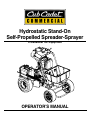
1
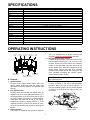
Hydrostatic Stand-On
Self-Propelled Spreader-Sprayer
Professional Turf Equipment
OPERATOR’S MANUAL
TABLE OF CONTENTS
Foreword ................................................................................................. 3
Safety Precautions .................................................................................. 4
A. General............................................................................................ 4
B. Related to Fuel ................................................................................ 4
C. When Spreading ............................................................................. 4
D. Personal Potective Equipment ........................................................ 4
Safety Decals .......................................................................................... 6
Specifications .......................................................................................... 7
Operating Instructions ............................................................................. 7
A. Controls ........................................................................................... 7
1.Ignition Switch................................................................................. 7
2.Fuel Shutoff Valve .......................................................................... 7
3.Engine Throttle ...............................................................................7
4.Ground Speed Control Levers ........................................................ 7
5.Freewheeling Valves ...................................................................... 7
6. Parking Brake ................................................................................ 8
7.Hour Meter and Tachometer........................................................... 8
B.Initial Adjustments ............................................................................ 8
C.Break-ln and Operation .................................................................... 8
D.Slope Operation ............................................................................... 9
Operation ................................................................................................ 10
A. Engine ............................................................................................. 10
B. Charging System ............................................................................. 10
C. Spreader.......................................................................................... 10
D. Sprayer............................................................................................ 10
E. Spreader and Sprayer Application Rates ........................................ 10
Maintenance............................................................................................ 12
A.General Maintenance ....................................................................... 12
B.Daily Maintenance After Spreading .................................................. 12
C.Maintenance Every 100 Hours ......................................................... 12
D.Lubrication Chart .............................................................................. 12
E.Engine Maintenance......................................................................... 12
F.Hydraulic System Maintenance ........................................................ 12
Spreader Calibration............................................................................... 14
Slope Gauge........................................................................................... 15
Warranty ....................................................................................BackCover
2
FOREWORD
The Cub Cadet Commercial Stand-On, Self-Propelled Spreader-Sprayer has been
developed for use by professional landscapers, commercial lawn service companies,
professional turf managers and golf course superintendents. The machines incorporate
many safety features that should be studied by all operators and maintenance
personnel before use. The list of safety precautions should receive particular attention.
This manual presents the operating and maintenance instructions necessary to keep
your Cub Cadet Commercial spreader at peak efficiency. If properly operated and
maintained, your Cub Cadet Commercial spreader-sprayer will give dependable and
trouble-free service.
Although hazard control and accident prevention partially are dependent upon the
design and configuration of the equipment, these factors are also dependent upon the
awareness, concern, prudence, and proper training of the personnel involved in the
operation, transport, maintenance and storage of the equipment.
CAUTION: THE Cub Cadet Commercial Stand-On, Self-Propelled SpreaderSprayer should only be operated and maintained by thoroughly trained
individuals. The machines could cause serious injury to anyone who misuses
them or does not understand their operation. All operators and maintenance
personnel are urged to read this entire manual for their personal safety.
•
•
•
•
WARNING-For the State of California
The engine exhaust, some of its constituents, and certain vehicle components contain or emit chemicals
known to the State of California to cause cancer, birth defects or other reproductive harm.
This unit is equipped with an internal combustion engine and should not be used on or near any unimproved
forest-covered, brush-covered, or grass-covered land unless the engine’s exhaust system is equipped with a
spark arrester meeting applicable local or state laws (if any). If a spark arrester is used, it should be maintained in effective working order by the operator.
In the State of California, the above is required by law (Section 4442 of the California Public Resources
Code). Other States may have similar laws. Federal laws apply to federal lands. A spark arrester muffler
may be available.
WARNING-For the State of California
A person shall not sell, offer for sale, lease, or rent to a person any equipment that is powered by an internal
combustion engine subject to Section 4442 or 4443, and not subject to Section 13005 of Health and Safety
Code, unless that equipment has a permanent writing label attached that is in plain view to the operator that
states, ‘WARNING-Operation of This Equipment May Create Sparks That Can Start Fires Around Dry
Vegetation. A Spark Arrestor May be Required. The Operator Should Contact Local Fire Agencies For
Laws or Regulations Relating to Fire Prevention Requirements.’
NOTE: The engine manufacturer is responsible for all engine-related issues with
regards to performance, power-rating, specifications, warranty and service.
Please refer to the engine manufacturer’s owner’s/operator’s manual, packed
separately with your unit, for more information.
3
SAFETY PRECAUTIONS
A. General:
5. Reduce speed when making sharp turns.
1. Read this Operator’s Manual completely before
starting the spreader. Study the controls and learn
the proper sequence of operation. Retain
Operator’s Manual in a safe place for future
reference.
6. Always have proper footing on slopes and hill
sides and never operate when conditions are
slippery. Be very careful on wet grass.
7. Always keep both hands on the handles.
8. Be careful when crossing gravel paths or roadways.
2. Do not allow anyone to operate or maintain this
machine who has not read the manual. Never
permit children under the age of 16 to operate
this machine.
9. Never leave the spreader-sprayer unattended
without placing the ground speed control levers in
neutral, engaging the park brake, shutting off the
engine and closing the fuel shutoff valve.
3. Always have your feet and hands clear of the
controls when starting the engine.
10. Always park the spreader-sprayer and start the
engine on a level surface with the ground speed
control levers in neutral, and the park brake
engaged.
4. Do not remove any shields, guards, decals or
safety devices. If a shield, guard, decal or safety
device is damaged or does not function, repair or
replace it before operating the spreader.
11. If you hit a solid object while spreading and
spraying, place the ground speed control levers in
neutral, engage the park brake and stop the
engine. Disconnect the spark plug wire and
inspect for damage. Repair any damage.
5. Always wear safety glasses, long pants and safety
shoes when operating or maintaining this
spreader. Do not wear loose-fitting clothing.
6. Never run the engine indoors without adequate
ventilation. Exhaust fumes are deadly.
12. Do not operate machine on excessively steep
(more than 15 degrees) slopes. Go laterally or
diagonally across the slope, not up and down the
slope.
7. To avoid serious burns, do not touch the engine or
muffler while the engine is running or until it has
cooled for at least 30 minutes after it has been
shut off.
13. Always disconnect the spark plug wire to prevent
the engine from accidentally starting before
performing any maintenance on this spreadersprayer.
B. Related To Fuel:
1. Gasoline is highly flammable. Respect it.
2. Do not smoke or permit others to smoke while
handling gasoline.
14. Keep the machine and especially the engine/pump
area clean and free of grease, grass and leaves to
reduce the potential for over heating and fire.
3. Always use approved containers for gasoline.
4. Always shut off the engine and permit it to cool
before removing the cap of the fuel tank.
5. If the fuel container spout will not fit inside the fuel
tank opening, use a funnel.
15. The speed and direction control levers located on
the handle are designed for your safety. Do not
modify them or operate the machine if they are
damaged.
6. When filling the fuel tank, stop when the gasoline
reaches one inch from the top. This space must be
left for expansion. Do not overfill.
D. General Requirements-Personal
Protective Equipment:
OSHA Standard 1910.132 through 1910.139
7. Wipe up any spilled gasoline.
OSHA standard 1910.132 states in relevant part:
a. Protective equipment, including personal
protective equipment (PPE) for eyes, face,
head, and extremities, protective clothing,
respiratory devices, and protective shields and
barriers, shall be provided, used, and
maintained in a sanitary and reliable condition
whereever it is necessary by reason of
hazards of processes or environment,
chemical hazards, radiological hazards, or
mechanical irritants encountered in a manner
capable of causing injury or impairment in the
function of any part of the body through
absortion, inhalation or physical contact.
8. Do not park or refuel machine in areas where
open flames, electrical switches and circuit
breakers are present.
C. When Spreading and Spraying:
1. Keep adults, children and pets away from the area
to be spread or sprayed.
2. Spread and spray only in daylight.
3. Always check the area to be spread and sprayed,
and remove debris and other objects prior to
spreading and spraying.
4. Watch for holes, sprinkler heads and other hidden
hazards.
4
This standard is subject to change. Please check www.osha.gov
for the latest regulatory updates
tal encapsulation (completely covering the wearer). An assortment of types of chemical-protective hats, hoods, gloves, and
boot covers are used with the garments.
General
There are many brands and models of protective equipment available for use in pesticide application. Price is not always an indicator of quality, so shop carefully.
Sometimes, it is not possible to reduce a hazard by eliminating it,
substituting a less hazardous process or product, making changes
to equipment, or even by changing how you do the job. That’s
when you need personal protection.
Note: Select equipment that is NIOSH tested and approved.
PPE includes items like gloves, goggles, boots, hearing protection
and respirators. Respirators filter out particles or block gases and
vapors that can harm the respiratory system. With a surface area
well supplied with blood vessels and equal in size to a tennis court,
the lungs are the quickest and most direct route for absorbing
harmful substance into your body.
Protective equipment, appropriate for the task and hazards that an
employee could be exposed, shall be provided by the employer.
Since comfort and proper fit must be considered, the person who
is going to use it must select the proper size to ensure correct fit
and function. Unused protective equipment does not help anyone.
Note: PPE does not prevent accidents, but it does prevent or reduce injury and even fatalities when used properly.
Note: Many supply centers, hardware stores, chemical retailers,
and equipment/machinery dealers keep protective equipment in
stock.
Equipment (PPE)
Protective equipment must be selected carefully. Always test fit
the protective equipment to be sure it fits properly and comfortably. If it isn’t comfortable -- it won’t be worn; if it isn’t worn -- it
won’t protect. PPE includes:
Training
Written procedures shall be developed for PPE use. These procedures shall include all information and guidance necessary for
their proper selection, use and care. The employer shall provide
fitting instructions including demonstrations and practice in how
the PPE should be worn, It is essential that both supervisors and
workers be properly instructed in PPE selection, use, and maintenance. Training shall provide the workers an opportunity to handle PPE, and have it fitted properly.
• respirators
• chemical-resistant clothing
• hearing protectors
• gloves
• safety goggles and glasses
When to replace PPE
• hard hats
All PPE shall be inspected routinely before and after each use. A
program for maintenance and care of PPE shall be initiated and be
adjusted to the type of work place, working conditions, and hazards. It shall include the following:
• sensors to detect hazardous substance
• communication devices used for safe
deployment of workers
• inspection for defects and damage
Inhaling pesticide fumes and mists is a very common entry route
of pesticides into the body. Absortion through the lungs is great
and the sensitivity is high.
• cleaning and disinfecting
• repair
The National Institute for Occupational Safety and Health
(NIOSH), under authority of the Federal Mine Safety and Health
Act of 1977 and the Occupational Safety and Health Act of 1970,
tests, approves, and certifies respiratory equipment as being safe
for its intended purpose.
• storage
Many factors influence how long PPE (especially respirators) remains effective. As well as hours of use, an air-purifying respirator’s service life is affected by the concentration of dust and other
contaminants in the enviroment; the user’s body size; how strenuously the user works while the respirator is worn; and how the respirator is stored.
Note: Always be certain that the NIOSH compliance number is
on the product before purchasing respiratory equipment.
Two systems of respiratory protection are available, depending
on the type of respiratory risk involved: air-purification (filtering)
and air-supplying. For most pesticide work, the air-purifying
equipment is adequate and safe.
Note: As a result, it’s not possible to specify a length of time after
which a respirator should be replaced.
In general, replace a mask or filter when it is visibly dirty or damaged, or when you experience difficulty breathing through it. Replace respirator cartridges when you can smell or taste chemical
while or after using the respirator, or according to the manufacturer’s recommendations. Replacement or repairs shall be done only
by experienced person with parts designed for the PPE. No attempts shall be made to replace components or to make adjustments or repairs beyond the manufacturer’s recommendations.
Protective equipment is usually required by the pesticide label in
one form or another and is integral to safe pesticide application.
Chemical-protective clothing consists of multilayered garments
made out of various materials that protect against a variety of hazards. Because no single material can protect against all chemicals, multiple layers of various materials usually are used to
increase the degree of protection. Protection is maximized by to-
5
SAFETY DECALS AND LABELS
Part Number: 777D12837
Part Number: 00030677
Part Number: 01009748
Part Number: 01009745
Part Number: 01003857
Part Number: 777I23060
Part Number: 01009747
6
SPECIFICATIONS
Model:
Engine Mfg:
HP:
Type:
Starter:
Air Cleaner:
Lube:
Fuel Capacity:
Charging System:
Battery:
Traction Drive:
Hydraulic Oil Capacity:
Hydraulic Filtration:
Ground Speed:
Wheels:
Width:
Height:
Length:
Weight:
<– – – – – 125 lb Spreader and 10 gallon Sprayer – – – – –>
<– – – – – Kawasaki – – – – –>
<– – – – –– 6.5 – – – – –>
<– – – – – 4 Cycle Single Cylinder – – – – –>
<– – – – –
Electric (Recoil Back-Up) – – – – –>
<– – – – – Dual Element Dry – – – – –>
<– – – – – Pressurized – – – – –>
<– – – – – 2 Quarts – – – – –>
<– – – – – 20 Amp Generator and Solid State Voltage Regulator – – – – –>
<– – – – – 12 VDC, 18 Amp-hour, Sealed – – – – –>
<– – – – – Hydro Gear, Model 510 Hydrostat – – – – –>
<– – – – – 0.7 Quarts – – – – –>
<– – – – – Internal – – – – –>
<– – – – – 0 to 5 mph – – – – –>
<– – – – – 18 x 8.50-8 rear, 13 x 7.50 front – – – – –>
<– – – – – 36” – – – – –>
<– – – – – 47” – – – – –>
<– – – – – 60” – – – – –>
<– – – – – 445 lbs. empty – – – – –>
OPERATING INSTRUCTIONS
Spreader
Switch
Hopper
Shut-Off
Reverse Ground
Speed Control
Spreader
3rd Hole
only. It is equipped with a “primer” that must be
pumped (1 time for initial starting) manually.
4. Ground Speed Control Levers:
Located on the right side of the control panel is the
forward speed control lever. The left lever is for
reverse. These two levers control the maximum
output of the hydrostatic transaxle and thus the
ground speed of the spreader independent of the
engine speed. Moving the right lever rearward
increases the forward speed and moving the left
lever rearward increases the reverse speed.
These levers moved in unison.
Spreader
Ignition
Side Deflector Switch
Sprayer
Switch
Forward Ground
Speed Control
Speed Control Lever
(Application-Transport)
Note: To start the engine both levers must be in
their neutral position.
A. Controls
1. Ignition Switch:
Located in the engine speed control panel, the
ignition switch stops and starts the engine and
also shuts off 12 VDC power to the spreader and
sprayer.
2. Fuel Shutoff Valve:
Located under the fuel tank, the handle turns 90
degrees to open or close. When the handle is in a
horizontal position, it will shut off the flow of fuel to
the engine. When it is turned to a vertical position,
it will open and allow fuel to flow to the engine.
Anytime the speader is being trailered or, if the
machine will not be in use for 30 minutes or more,
close the fuel shutoff valve to prevent flooding the
engine.
3. Engine Throttle:
This engine is equipped with governed high-idle
5. Freewheeling Valve:
A valve is located on the side of the hydrostatic
transaxle. When the lever is moved into the “J”
slot the spreader-sprayer can be pushed forward
or pulled in reverse without the engine running. See
photo below.
Freewheeling
Valve Lever
7
OPERATING INSTRUCTIONS
this machine.
2. Check the engine oil level. Fill to the proper level
with 10W30 engine oil rated for service SF or
higher.
6. Parking Brake:
The mechanical disc brake is activated by the
lever in the foot platform area. Press down on the
lever to engage the park brake, and lift up the
lever to release.
Note: 10W40 and Shell Rimula 15W40 are approved.
3. Move the machine outdoors. Check the engine
gasoline level. When filling the tank, stop when the
gasoline reaches one inch from the top. This
space must be left for expansion. Use fresh,
clean, unleaded, regular gasoline.
4. Move the machine to a “test area” where you can
operate it for about a half an hour without being
disturbed.
5. To start the engine:
a.
Parking Brake
b.
c.
d.
Note: The Parking Brake must be engaged to start
the engine.
7. Hour Meter and Tachometer:
Located at the upper left edge of the control panel.
When the machine is running the tachometer
displays engine rpm. When the machine is off it
displays time of operation.
e.
Make sure that the ground speed control levers are in
the neutral position and the park brake is engaged.
Connect the spark plug wire.
Open the fuel shutoff valve.
Pump the primer (1 time if this is the first start of
the day).
Turn the Ignition Switch or pull the recoil handle.
Note: Do not crank the engine more than 30 seconds at one
time, because it could damage the starter.
6. Move the forward ground speed control lever to
contact the application stop.
B. Initial Adjustments
1. Disconnect the spark plug wire.
2. Check the tire pressure. Drive wheels should be
inflated to 15 psi. Front wheels (unless foam-filled)
should be inflated to 15 psi. Note: New tires are
overinflated in order to properly seat the bead to
the rim.
3. Check that all nuts, bolts and screws are tight.
4. The tension of the transaxle drive belt should be
adjusted so that a five pound pull between the
engine traction drive pulley and the pump drive
pulley opposite the idler pulley deflects the belt
about 3/16”.
5. The long speed control cables which connect to
the pump control levers should initially be adjusted
so that when the ground speed control levers are
in neutral, and the speed levers are relesed from
the neutral position, the machine stands still with
the engine running. If the machine starts to creep
forward or to the rear in this situation, then the
speed control cable must be adjusted. Loosen the
nut on the cable and adjust until the drive wheel
stops moving. Then retighten the nut.
6. Lubricate all fittings listed in the maintenance
section.
CAUTION
Set the ground speed control lever in the application position until you are fully familiar with
the operation of the machine.
7. To turn the machine, move the control handle to
the side opposite of the way you want to turn, I.E.,
move the control handle left and the machine
turns right. Move the control handle right, and the
machine turns left.
8. To stop the mower’s forward motion, release the
forward and reverse speed control levers.
9. Before moving into reverse, the machine’s forward
motion should be completely stopped.
10. Practice operating the machine and as you gain
confidence, move the ground speed selector lever
to the transport position. Operate the machine
until you are comfortable and confident with the
controls.
11. To stop and shut off the machine, release both
speed control levers, turn the ignition switch to the
“off” position to stop the engine, close the fuel
shutoff valve, and disconnect the spark plug wire.
C. Break-In and Operation
1. Make certain you thoroughly understand all of the
safety precautions before you attempt to operate
8
OPERATING INSTRUCTIONS
12. After the first full day of use, all nuts, bolts and
screws should be rechecked for proper tightness
and the belts should be rechecked for proper
tension.
DO NOT:
• Do not turn on slopes unless necessary; then,
turn slowly and use extra care.
• Do not operate near drop-offs, ditches or embankments. The unit could suddenly turn over if a wheel
is over the edge of a cliff or ditch, or if an edge
caves in.
• Do not operate on wet grass. Reduced traction
could cause sliding.
• Do not try to stabilize the machine by putting your
foot on the ground.
NOTE:
Set the ground speed control lever at the
desired speed for spreading or spraying. Refer
to the application chart on page 10 & 11.
D. Slope Operation
Slopes are a major factor related to loss of
control and tip-over accidents, which can result
in severe injury or death.
Note: All slopes require extra caution. If you cannot back up the slope or if you feel uneasy on it, do
not 90 on it.
For your safety, use the slope gauge included as a part
of this manual (see pg. 15) to measure slopes before
operating this unit on a sloped or hilly area. If the slope
is greater than 15 degrees as shown on the slope
gauge, do not operate this unit on that area or serious
injury could result.
DO:
• Go across slopes, not up and down.
• Remove obstacles such as rocks, limbs, etc.
• Watch for holes, ruts or bumps. Uneven terrain
could overturn the machine. Tall grass can hide
obstacles.
• Use slow speed. Choose a low enough speed so
that you will not have to stop while on the slope.
• Follow the manufacture’s recommendations for
counterweights with attachments to improve stability.
• Keep all movement on the slopes slow and gradual. Do not make sudden changes in speed or
direction. Rapid acceleration or deceleration could
cause the front of the machine to lift and rapidly flip
over backwards, which could cause serious injury.
• Avoid starting or stopping on a slope. If the tires
lose traction, disengage the blades and proceed
slowly straight down the slope.
9
OPERATION
A. Engine
C. Spreader
The Kawasaki engine incorporates an electric start but
retains the recoil start feature as a back-up. This
engine has pressurized lubrication.
The spreader is powered by a sealed 12 VDC motor
with worm-gear reduction. The impeller operates all
the time when the switch is activated, and the 12 VDC
motor operates a constant speed providing a uniform
spread pattern. The application rate will vary with
travel speed. Refer to the chart on page 11.
B. Charging System
This machine is equipped with a belt-driven 20 AMP
capacity generator (dynamo) with a solid state voltage
regulator. The regulator will maintain the system
voltage above 13 VDC when the engine is running,
regardless of whether the spreader and/or sprayer are
being operated. The battery is a sealed 12 VDC - 18
AMP-hour rated lead-acid type.
D. Sprayer
The spraying system includes a 12 VDC powered
two- diaphragm pump, a strainer, two off center
nozzles, one wide angle nozzle (center), two 5 gallon
tanks with shut-off valves and two splash-proof caps.
The system operates at approximately 45 psi with the
engine running and 40 psi when it is off.
E. Spreader and Sprayer Application Rates
The spreader-sprayer operates at an average system pressure of 45 lb/in2. The 20 amp
charging system provides adequate electrical power for the spreader, sprayer, or both
together. With the system pressures and spray tips listed below, the effective spray width
will be 9 feet and the output will be as indicated for 45 lb/in2.
Sprayer Application Rate for Pressure and Travel Speed
4 mph
5 mph
6 mph
35 psi, one Tee-Jet X"R11001VB" tip and two "OC-01 Brass" tips
Output
0.281 gal/min………………………………………………..
gal/acre
3.59
2.87
2.39
2
gal/1000 ft
0.082
0.066
0.055
40 psi, one Tee-Jet X"R11001VB" tip and two "OC-01 Brass" tips
Output
0.300 gal/min…………………………………………………..
gal/acre
4.12
3.30
2.75
2
gal/1000 ft
0.095
0.076
0.063
45 psi, one Tee-Jet X"R11001VB" tip and two "OC-01 Brass" tips
Output
0.315 gal/min………………………………………………..
gal/acre
4.33
3.47
2.89
2
gal/1000 ft
0.100
0.079
0.066
Note:
The above values are based on manufacturer's information at 700 F, and actual
values may vary based on chemical additives, temperature, as well as system
cleanliness and wear.
Note: See page 11 for the spreader application rates
10
OPERATION
The electric-powered spreader maintains an impeller speed to provide an effective material
spread width of 10 feet.
Spreader Application Rate de-rating for travel speed
Speed
3.5 mph
4 mph
5 mph
6 mph
7 mph
8 mph
Time/100 ft
19.5 seconds
17.0 seconds
13.6 seconds
11.4 seconds
9.7 seconds
8.5 seconds 11
Application Rate (AR)
1.0 X AR
0.875 X AR
0.70 X AR
0.58 X AR
0.50 X AR
0..438 X AR
MAINTENANCE
D. LUBRICATION CHART:
WARNING
NUMBER OF GREASING POSITIONS
(See Figure 1 and 2 below for Item Locations.)
Disconnect the spark plug wire to prevent
the engine from accidentally starting before
40 HOUR LUBRICATION CHART
1 A
2 B
2 C
performing any maintenance on this machine.
Front Wheel Bearing
Pivot Shafts
Front Axle Bearing
A. General Maintenance
1. If the machine must be tipped on its side for
maintenance, first drain the fuel from the fuel tank,
and the oil from the engine’s crankcase.
2. Be careful not to spill oil on any of the belts.
3. Do not tamper with the engine’s governor settings.
They are adjusted to provide the proper maximum
engine speed.
4. If the machine is to be in storage for more than 30
days, drain the fuel tank, run the engine to drain the
carburetor dry, change the oil, remove the spark
plug and pour a teaspoonful of oil into the cylinder.
Pull the starter to crank the engine and distribute
the oil then replace the spark plug.
B. Daily Maintenance After Spreading
1. Park the machine outside the storage facility with
the engine shut off.
2. Close the fuel shutoff valve.
3. Permit the machine to cool.
4. Disconnect the spark plug wire.
5. Wash the machine off with water. Be sure to clean
out materials from under the hopper. Allow the
machine to dry before storing.
6. Check the fuel level, the engine oil level and clean
the cooling-air intake (the rotating screen).
7. Clean the air cleaner elements (foam and paper).
8. After the first 5 hours of use, change the engine oil.
(Change the oil every 100 hours thereafter).
9. Follow the lubrication chart at the top of the page.
10. Place the machine in locked storage to avoid
tampering or use by an untrained operator.
Figure 1
Figure 2
C. Maintenance Every 100 Hours
1. Change the engine oil. (Change the engine oil more
frequently under severe operating conditions).
2. Check that all nuts, bolts and screws are tight.
3. Check the condition and tension of transaxle belt.
4. Clean the spark plug and check the spark plug gap.
5. Follow the lubrication chart at the top of the page.
E. ENGINE MAINTANENCE:
For detailed maintenance instructions for the engine on
your mower, see the separate engine manual packed
with your mower.
F. HYDRAULIC SYSTEM MAINTANENCE:
The hydraulic system does not require any maintenance.
The transaxle is not owner repairable. If you have a
problem with a transaxle, please contact your service
center for a replacement. Do not disassemble the
transaxle.
12
MAINTENANCE
Engine Oil: Use 10W30, 10W40 or Shell Rimula
15W40 oil rated SF or higher.
General Purpose Lubrication: Use any NLGI grade 2
multi-purpose grease.
Shell Albida EP2 is
recommended. Shell Albida EP 2 is a red-colored
multi-purpose grease designed for heavy-duty bearing
applications.
It has high base oil viscosity for
mechanical stability, has been formulated for high
load, low-speed applications, and has excellent
lubrication and corrosion protection.
13
SPREADER CALIBRATION
Two items must be considered when calibrating a spreader. The first
is the distribution pattern of the spreader. That is, the pattern the product makes as it strikes the ground after being thrown out by the
spreader's impeller. There are many factors which affect the distribution pattern of a rotary spreader and some of them relate directly to
the product. For this reason, we recommend that the spreader be calibrated separately for every product to be applied. Spreader calibration should be checked at least once a month, or more often when the
spreader is used frequently.
The second item is the product application rate, that is the amount of
product applied per thousand square feet. This is important because
over-application can be costly and may cause plant injury, while under-application will reduce the effectiveness of the product.
TO USE THE CALIBRATION GAUGES:
The Calibration Gauges provide a series of "steps", numbered in 1/
32-inch increments, that will allow you to "fine-tune" the spreader.
Once you have calibrated your rotary spreader for the product chosen, open the operating lever and insert the calibration gauges until
you determine which step fits tightly into one of the open holes in the
hopper bottom. Record that step number for future reference when
using that product. You may choose to set other rotary spreaders for
application of the same product by adjusting the shut off plate to that
calibration gauge step. This will provide consistent settings for all of
your spreaders. To recalibrate your rotary spreader after a period of
use, adjust the rate control arm to the "24" position. Open the operating lever and insert the even-numbered Calibration Gauge into one of
the open holes in the hopper bottom. Close the operating lever and let
the shut off plate on the underside of the hopper make contact with
the number 10 step on the Calibration Gauge. Move the rate control
arm back toward the "6" position until the bottom of the arm makes
contact with the shut off plate. If your spreader is properly adjusted,
the top of the rate control arm should be at setting "10". To correct
variances, remove the rate control arm, place the bottom of the arm
(up to the bolt hole) in a vise, and bend either to the right or the left.
TO CALIBRATE A SPREADER, FOLLOW THESE
STEPS:
Check the spreader discharge holes with the operating lever in the
closed position. If the discharge holes are not fully closed, thread the
upper jam nut on the operating lever rod further up the rod. Tighten
the lower locknut and recheck. Repeat this procedure until the holes
are fully closed.
TO ACHIEVE A UNIFORM DISTRIBUTION PATTERN:
The accurate method for checking pattern uniformity is to lay out shallow boxes or pans in a row on a line perpendicular to the direction of
spreader travel. Eleven boxes or pans, two inches high placed on
one-foot centers will provide accurate calibration. To conduct the test,
begin with the pattern slide completely open and set the rate control
arm at the suggested approximate setting. Make three passes over
the boxes, pushing the spreader in the same direction each time. The
product caught in each box is then evaluated to determine the distribution pattern. Weighing the product in each box is the most accurate,
but a simpler method is to pour the contents of each box into a separate small vial or bottle. Then set the eleven vials or bottles side-byside in order. This makes the pattern variation quite visible.
To reduce the amount of discharge to the right side (operator's right)
the pattern slide should be partially closed and the test repeated until
the distribution pattern is uniform.
TO ACHIEVE THE CORRECT PRODUCT APPLICATION RATE:
The approximate spreader settings printed on any product label
should only be used as the initial setting for calibration. Set the rate
control arm at this approximate setting. Using the collection boxes or
pans, make a single pass over them to determine the effective pattern
width. The effective pattern width is twice (2x) the distance to the point
where the rate drops to one-half the average rate at the center. Example: If the product in the vials from the center boxes averages two
inches in depth, count out to the vial which has one inch of product. If
this is the fifth vial from the center and the boxes were on one-foot
centers, the effective pattern width is ten feet (2 x 5 ft.).
SPREADER TIPS:
1. Operate the spreader at a consistent speed (approximately 3.5
m.p.h. is recommended) and is achieved when the speed control
lever is set for application.
Knowing the effective pattern width (ten feet), measure out a lineal
distance to equal 1,000 sq. ft. (10 ft. x 100 ft. = 1,000 sq. ft.). Weigh
20 lbs. of product and place it in the spreader hopper and spread it
over the distance necessary to equal 1,000 sq. ft. (100 ft.). Then
weigh the product left in the hopper and subtract this amount from the
amount with which you started. The result is the application rate for
this product in pounds per 1,000 sq. ft. that your spreader is currently
adjusted to disperse. Adjust the rate control arm up or down as needed and repeat this procedure until the correct application rate is
achieved.
2. Always close the operating lever before filling the hopper.
3. Be sure the screen is in place to prevent lumps or paper scraps
from plugging the holes in the hopper bottom.
4. Always start driving forward before opening the operating lever;
close the operating lever before forward motion is stopped.
5. Empty the spreader after each use. Wash the spreader thoroughly
and allow it to dry. Keep the impeller clean.
6. Lubricate all moving parts. Apply grease to the five grease fittings;
two in the axle supports, two in the gear support and one in the idler
wheel (if the idler wheel has a steel hub).
14
SLOPE GAUGE
DO
NE
, RE
PRE
S
E
NTIN
G
A 15
°S
LOP
E
OR A FENCE POST
A CORNER OF A BUILDING
A POWER POLE
SIGHT AND HOLD THIS LEVEL WITH A VERTICAL TREE
USE THIS PAGE AS A GUIDE TO DETERMINE SLOPES WHERE YOU MAY NOT OPERATE SAFELY.
FOL
ND
O
T
TED
LI
15°
WARNING
Do not operate on inclines with a slope in excess of 15 degrees (a rise of approximately 2-1/2 feet every 10 feet). A riding unit
could overturn and cause serious injury.
Operate the unit across the face of slopes, never up and down slopes.
15
This page intentionally left blank.
16
This page intentionally left blank.
17
CALIFORNIA EMISSION CONTROL WARRANTY STATEMENT
YOUR WARRANTY RIGHTS AND OBLIGATIONS
The California Air Resources Board and MTD Consumer Group Inc are pleased to explain the evaporative emission control system warranty on your 2008 lawn
mower. In California, new lawn mowers must be designed, built and equipped to meet the State’s stringent anti-smog standards. MTD Consumer Group Inc must
warrant the EECS on your lawn mower for the period of time listed below provided there has been no abuse, neglect or improper maintenance of your lawn mower.
Your EECS may include parts such as the carburetor, fuel-injection system, the ignition system, catalytic converter, fuel tanks, fuel lines, fuel caps, valves,
canisters, filters, vapor hoses, clamps, connectors, and other associated emission-related components.
Where a warrantable condition exists, MTD Consumer Group Inc will repair your lawn mower at no cost to you including diagnosis, parts and labor.
MANUFACTURER’S WARRANTY COVERAGE:
This evaporative emission control system is warranted for two years. If any evaporative emission-related part on your equipment is defective, the part will be
repaired or replaced by MTD Consumer Group Inc.
OWNER’S WARRANTY RESPONSIBILITIES:
As the lawn mower owner, you are responsible for performance of the required maintenance listed in your owner’s manual. MTD Consumer Group Inc recommends
that you retain all receipts covering maintenance on your lawn mower, but MTD Consumer Group Inc cannot deny warranty solely for the lack of receipts.
As the lawn mower owner, you should however be aware that MTD Consumer Group Inc may deny you warranty coverage if your lawn mower or a part has failed
due to abuse, neglect, or improper maintenance or unapproved modifications.
You are responsible for presenting your lawn mower to MTD Consumer Group Inc’s distribution center or service center as soon as the problem exists. The
warranty repairs should be completed in a reasonable amount of time, not to exceed 30 days. If you have a question regarding your warranty coverage, you should
contact the MTD Consumer Group Inc Service Department at 1-800-800-7310.
GENERAL EMISSIONS WARRANTY COVERAGE:
MTD Consumer Group Inc warrants to the ultimate purchaser and each subsequent purchaser that the lawn mower is: Designed, built and equipped so as to
conform with all applicable regulations; and free from defects in materials and workmanship that cause the failure of a warranted part to be identical in all material
respects to that part as described in MTD Consumer Group Inc’s application for certification.
The warranty period begins on the date the lawn mower is delivered to an ultimate purchaser or first placed into service. The warranty period is two years.
Subject to certain conditions and exclusions as stated below, the warranty on emission-related parts is as follows:
1. Any warranted part that is not scheduled for replacement as required maintenance in the written instructions supplied, is warranted for the warranty period
stated above. If the part fails during the period of warranty coverage, the part will be repaired or replaced by MTD Consumer Group Inc according to subsection
(4) below. Any such part repaired or replaced under warranty will be warranted for the remainder of the period.
2. Any warranted part that is scheduled only for regular inspection in the written instructions supplied is warranted for the warranty period stated above. Any such
part repaired or replaced under warranty will be warranted for the remaining warranty period.
3. Any warranted part that is scheduled for replacement as required maintenance in the written instructions supplied is warranted for the period of time before the
first scheduled replacement date for that part. If the part fails before the first scheduled replacement, the part will be repaired or replaced by MTD Consumer
Group Inc according to subsection (4) below. Any such part repaired or replaced under warranty will be warranted for the remainder of the period prior to the
first scheduled replacement point for the part.
4. Repair or replacement of any warranted part under the warranty provisions herein must be performed at a warranty station at no charge to the owner.
5. Notwithstanding the provisions herein, warranty services or repairs will be provided at all of our distribution centers that are franchised to service the subject
engines or equipment.
6. The lawn mower owner will not be charged for diagnostic labor that is directly associated with diagnosis of a defective, emission-related warranted part,
provided that such diagnostic work is performed at a warranty station.
7. MTD Consumer Group Inc is liable for damages to other engine or equipment components proximately caused by a failure under warranty of any warranted
part.
8. Throughout the lawn mower warranty period stated above, MTD Consumer Group Inc will maintain a supply of warranted parts sufficient to meet the expected
demand for such parts.
9. Any replacement part may be used in the performance of any warranty maintenance or repairs and must be provided without charge to the owner. Such use will
not reduce the warranty obligations of MTD Consumer Group Inc.
10. Add-on or modified parts that are not exempted by the Air Resources Board may not be used. The use of any non-exempted add-on or modified parts by the
ultimate purchaser will be grounds for disallowing a warranty claims. MTD Consumer Group Inc will not be liable to warrant failures of warranted parts caused
by the use of a non-exempted add-on or modified part.
18
WARRANTED PARTS:
The repair or replacement of any warranted part otherwise eligible for warranty coverage may be excluded from such warranty coverage if MTD Consumer Group
Inc demonstrates that the lawn mower has been abused, neglected, or improperly maintained, and that such abuse, neglect, or improper maintenance was the
direct cause of the need for repair or replacement of the part. That notwithstanding, any adjustment of a component that has a factory installed, and properly
operating, adjustment limiting device is still eligible for warranty coverage. The following emission warranty parts are covered:
(1) Fuel Metering System
s#OLDSTARTENRICHMENTSYSTEMSOFTCHOKE
s#ARBURETORANDINTERNALPARTS
s&UELPUMP
s&UELTANK
(2) Air Induction System
s!IRCLEANER
s)NTAKEMANIFOLD
(3) Ignition System
s3PARKPLUGS
s-AGNETOIGNITIONSYSTEM
(4) Exhaust System
s#ATALYTICCONVERTER
s3!)2EEDVALVE
(5) Miscellaneous Items Used in Above System
s6ACUUMTEMPERATUREPOSITIONTIMESENSITIVEVALVESANDSWITCHES
s#ONNECTORSANDASSEMBLIES
(6) Evaporative Control
s&UELHOSECERTIFIEDFOR!2"EVAPORATIVEEMISSIONS
s&UELHOSECLAMPS
s4ETHEREDFUELCAP
s#ARBONCANISTER
s6APORLINES
'$/#2EV#
19
MANUFACTURER’S LIMITED WARRANTY FOR CUB CADET COMMERCIAL
LAWN APPLICATION EQUIPMENT
IMPORTANT: To obtain warranty coverage owner may be required
present proof of purchase and applicable maintenance records to the
servicing dealer. Please see the operator’s manual for information on
required maintenance and service intervals. In addition, Cub Cadet
may deny warranty coverage if the hour meter, or any part thereof, is
altered, modified, disconnected or otherwise tampered with.
The limited warranty set forth below is given by Cub Cadet LLC with
respect to new merchandise used for commercial and related purposes
purchased and used in the United States and/or its territories and
possessions, and by MTD Products Limited with respect to new
merchandise purchased and used in Canada and/or its territories and
possessions (either entity respectively, “Cub Cadet”).
Cub Cadet warrants this product (excluding its No-Fault Components,
as described below) against defects in material and workmanship for a
period of one (1) year from the date of original retail purchase or lease
and will, at its option, repair or replace, free of charge, any part found
to be defective in materials or workmanship.
No-Fault Components include only belts, tires, and seats which are
warranted to be free from defects in material and workmanship for a
period of thirty (30) days from the date of original purchase or lease.
HOW TO OBTAIN SERVICE: Warranty service is available, WITH
PROOF OF PURCHASE AND APPLICABLE MAINTAINCE
RECORDS, through your local authorized service dealer. To locate the
dealer in your area;
In the U.S.A.:
Check your Yellow Pages, or contact Cub Cadet LLC at P.O. Box
361131, Cleveland, Ohio 44136-0019, or call 1-877-282- 8684, or log
on to our Web site at www.cubcadetcommercial.com.
In Canada:
For all provinces excluding Quebec contact Modern Power Products
d/o MTD Canada Ltd. At 60 Ottawa Street South, Kitchener, Ontario
N2G 3S7 or call 1-800-567-6775 or log on to our website at
www.cubcadet.ca.
In Quebec contact Les Distributions RVI Ltee. d/o MTD Canada Ltd.
2955 jean-Baptiste Deschamps, Ville Lachine, Quebec H8T 1C5 or
call 1-800-361-5770 or log on to our website at www.cubcadet.info.
This limited warranty does not provide coverage in the following cases:
a.
Routine maintenance items such as lubricants, filters, tuneups, brake adjustments, clutch adjustments, control linkages,
drive system, engines, and normal deterioration of the exterior
finish due to use or exposure.
b.
Service completed by someone other than an authorized
service dealer.
c.
For products sold or exported outside of the United States
and/or Canada, and their respective possessions and
territories, except those sold through Cub Cadet’s authorized
channels of export distribution.
d.
Damage or failure resulting from the use of defective or
improper peplacement parts and\or accessories other than
genuine Cub Cadet parts.
e.
Transportation charges and service calls.
f.
Failure to operate and maintain the product in accordance with
the Operator’s Manual furnished with the product,
g.
Damages and failures resulting from misuse, abuse, neglect,
accident, improper maintenance, alteration, vandalism, theft,
fire, water, or damage because of other peril or natural
disaster.
There are no implied warranties, including without limitation any
implied warranty of merchantability or fitness for a particular
purpose. No warranties shall apply after the applicable period of
express written warranty above. No other express warranties
beyond those mentioned above, given by any person or entity,
including a dealer or retailer, with respect to any product, shall
bind Cub Cadet. The exclusive remedy is repair or replacement
of the product as set forth above. The terms of this warranty
provide the sole and exclusive remedy arising from the sale
and/or lease of the products covered hereby. Cub Cadet shall not
be liable for any incidental or consequential loss or damage
including, without limitation, expenses incurred for substitute or
replacement lawn care services or for rental expenses to
temporarily replace a warranted product.
Some jurisdictions do not allow the exclusion or limitation of incidental
or consequential damages, or limitations on how long an implied
warranty lasts, so the above exclusions or limitations may not apply to
you. This limited warranty gives you specific legal rights, and you may
also have other rights that vary in different jurisdictions.
In no event shall recovery of any kind be greater than the amount of
the purchase price of the product sold. Alteration of safety features
of the product shall void this warranty. You assume the risk and
liability for loss, damage, or injury to you and your property and/or to
others and their property arising out of improper use, misuse or
inability to use the product. This limited warranty shall not extend to
anyone other than the original purchaser/Leasee or to the person for
whom it was purchased or leased as a gift.
Cub Cadet LLC - P.O. Box 361131, Cleveland, Ohio 44136-0019; Phone 1-877-282-8684
Form #769-04150 Rev. 09-0 11/12/2008