1
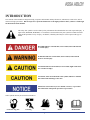
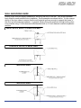
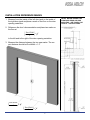
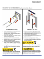
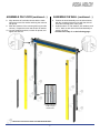
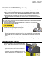
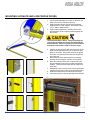
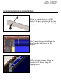
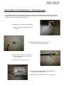
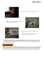
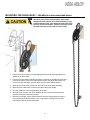
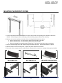
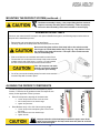
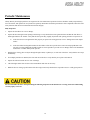
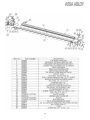
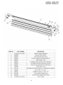
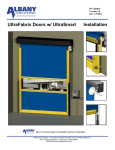
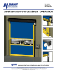
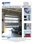
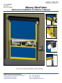
PN: 6410T0021 Version F Rev: 03-13-2014 Albany UltraFabric Mechanical Installation and Owner’s Manual Doors are Ultra-Tough, Ultra-Reliable, and Ultra-Affordable. ASSA ABLOY Entrance Systems Albany High Performance Door Solutions 975A Old Norcross Road Lawrenceville, GA 30046 Tel: (770) 338-5000 Fax: (770) 388-5024 www.assaabloyentrance.com INTRODUCTION The contents of this manual are designed to help you operate and maintain Albany UltraLite™, UltraFast™, UltraCool™, and UltraFreeze™ high speed doors. DO NOT operate or perform maintenance on the high speed door unless you have read through the instructions in this manual. The safety alert symbol is used to identify safety information about hazards that can result in personal injury. A signal word (DANGER, WARNING, or CAUTION) is used with the safety alert symbol to indicate the likelihood and the potential severity of injury. In addition, a hazard symbol may be used to represent the type of hazard. DANGER indicates a hazard that, if not avoided, will result in death or serious injury. WARNING indicates a hazard that, if not avoided, could result in death or serious injury. CAUTION indicates a hazard that, if not avoided, might result in minor or moderate injury. CAUTION, when used without the alert symbol, indicates a situation that could result in damage to the door. NOTICE is used to inform you of a method, reference, or procedure that could assist with specific operations or procedures. Other symbols that may be used in this manual are: Lock Out / Tag Out Crushing Fire 1 Shock Read Manual DOOR INSTALLATION TOOLS AND MATERIALS REQUIRED Personnel Two people to install the door One person qualified to operate forklift, hoist, or crane One electrician to install and connect the control panel and all electrical wiring Improper installation of anchoring devices or installation into aged or unsound concrete block, or other wall material may result in premature wear, product failure, property damage, or serious personal injury. Tools Lock-Out Tag-out all electrical power supplied to the door before making any electrical installations or connections. Also Lock-out Tag-out any equipment near the installation site if that equipment may be inadvertently operated into the area used to assemble and install the door. Failure to properly deenergize electrical circuits and disable equipment during installation and/or maintenance could result in death or serious injury. Assorted wrenches Tape measure Carpenter’s square Level (4ft minimum recommended) Lifting device (fork lift, hoist, crane) Lifting Straps 2 ladders or personnel lifts (tall enough to reach above the door head) Other tools as needed for the type of anchoring chosen Materials Use proper lifting equipment and techniques. Properly secure all loads. Failure to properly secure all lifting loads could result in death or serious injury. Secure the work area so that persons not working directly on the installation do not enter the work area. Anchors appropriate for the type of wall the door and accessories are to be installed onto. Albany Doors recommends throughbolting doors whenever possible. Wire as specified on the electrical schematic Electrical supplies needed to comply with all regulating body electrical codes and standards. See applicable control manual with door. SITE PREPARATION UNPACKING AND PREPARING Electrical Supply Qualified electrician must make all electrical mountings and connections in accordance with all applicable regulating body(s) electrical codes and standards. . See applicable electrical manual for specifications and wiring instructions.. 1. Inspect and unpack the components. Report any damage immediately to Albany at 877-925-2468. Refer to the serial number tag located on the right door column. 2. DO NOT cut the banding which holds the door in a roll until instructed to do so in a later procedure. Door Opening 1. Are the door jambs and support wall structurally sound providing a flat surface for the side columns to mount against? 2. Check the width and height of the door opening and verify the measurements against the dimensions of the door. 3. Is the opening square? Plumb? 4. Is the floor level across the opening? Make all necessary structural repairs and improvements to provide a “yes” answer to each of the questions above. The door panel and roll assembly could be damaged. Use evenly spaced padded supports to prevent rips, tears, or bending of the roll assembly. Failure to protect the roll assembly could result in damage to the door. 2 WALL ANCHORING GUIDE Albany Doors does not supply hardware for mounting the door to the wall. Use proper hardware best suited for each particular door installation. Some examples are shown below. It is the responsibility of the door owner to ensure that the wall material is strong enough to support the forces of the door and all anchoring hardware. In general, Albany Doors recommends through-bolting wherever possible using 1/2 inch diameter bolts/threaded-rods or 1/2 inch diameter concrete expansion anchors. WOOD, BLOCK, BRICK, or INSULATED WALL CONCRETE, BLOCK, or BRICK WALL INSULATED WALL INSULATED WALL 3 INSTALLATION REFERENCE MARKS 1. Measure from the inside of the left door jamb to the inside of the right door jamb and place a mark on the floor on the door opening centerline. 2. Reference the door’s documentation and place two marks on the floor at DoorWidth 3 4" 2 to the left and to the right of the door opening centerline. 3. Measure the distance between the two new marks. The correct distance should be DoorWidth + 1.5” DoorWidth 3 4" 2 DoorWidth 3 4" 2 4 DETAIL BELOW SHOWN FOR STANDARD REAR COLUMN MOUNTING. SEE PAGE 8 FOR UltraLite™ INSTRUCTIONS. MOUNTING THE DOOR ASSEMBLY (optional methods shown) ASSEMBLE ON FLOOR ASSEMBLE ON WALL 1. Lay the head assembly on its back on the floor in a clean area in front of the door opening. 2. Remove the bolts securing the yellow front columns to the side columns. Remove and set the yellow front columns off to the side. 3. Position each side column in line with the mounting brackets on the head assembly. 4. Slide the side columns onto the head assembly. Install the three 1/2” flat washers, lock washers, and 1/2”x1” bolts. 5. Square the side columns to the head assembly and tighten the three bolts on each side. 6. If the door was ordered with the optional counterweights, slide the weights into the side columns far enough to install the temporary retainer bolt. Install the nut finger-tight. Note the “LEFT” and “RIGHT” markings. 7. Using a safe lifting device, carefully lift the entire door assembly up to a vertical position against the door jambs. 1. Hold the left side column in place against the wall. Align the base with the marking placed on the floor earlier and bring the column into plumb. 2. Mark the locations of the four mounting holes. Prepare the holes and anchor as needed. 3. Loosely install the anchors, recheck for plumb, and tighten the anchors. 4. Repeat steps 1-3 for the right side column. 5. Lay the head assembly on its back on the floor in front of the door opening. Using a safe lifting device, carefully lift the head assembly up into position above the side columns. The head assembly is heavy. Use proper lifting devices and techniques to securely and safely lift the head assembly. Failure to properly secure the head assembly could result in death or serious injury. The head assembly must be lifted level (balanced) and with the mounting brackets and motor hanging straight down. Failure to properly position the head assembly could result in damage to the mounting brackets and/or the side columns. The door assembly is heavy. Use proper lifting devices and techniques to securely and safely lift the door assembly. Failure to properly secure the door assembly could result in death or serious injury. 5 ASSEMBLE ON FLOOR (continued…) ASSEMBLE ON WALL (continued…) 8. Align the base of each side column with the markings place on the floor earlier and bring the columns into plumb. 9. Mark the locations of the mounting holes (4 per side column). Prepare the holes and anchor as needed. 10. Loosely install the anchors, recheck for plumb, and tighten the anchors. 6. Position the head assembly over the side columns with the mounting brackets in line with the side columns and carefully lower it into place. 7. Install the three 1/2” flat washers, lock washers, and 1/2”x1” bolts on each side of the head assembly to secure it in place. continue on to step 11 on the following page... 8” long temporary counterweight retainer bolt. - INDICATES LOCATION OF FRONT COLUMN MOUNTING BOLT 6 MOUNTING THE DOOR ASSEMBLY (continued…) 11. The photo safety cables are marked and bundled on top of the head assembly at the junction box. Route the light curtain cables through the holes located at the rear bottom of the mounting brackets as shown. 12. Secure the cables to the sides of the columns using the clips supplied and plug them into the appropriate photo device mounted in the column—note the matching cable markings. Ensure that all loose slack in the cables is removed. Photo devices are located behind foam insulation on UltraFreeze model doors. 13. UltraFreeze doors will have heat tape in the side columns. Route the power cords for the heat tape up through the holes located at the rear bottom of the mounting brackets to the junction box on top of the head assembly. COUNTERWEIGHTS—OPTIONAL EQUIPMENT If the door was ordered with counterweights for the optional BacOut egress system, the following steps must be taken at this point in the installation process: 1. Remove the tie wraps from the counterweight straps and route the straps down to the counterweights. 2. Remove any twists that may be in the straps Do not allow the straps to be twisted or slack. Twisted or loose straps will result in damage to the straps. 3. Loop each strap between the two clamping plates as shown. 4. Pull and hold the straps tight and tighten the clamping bolts. 5. Ensure that all cables/straps are secure and free of any obstructions. 14. Set the yellow front columns into the side columns. If the door was ordered with light curtains, position the front light curtain and mounting bracket against the outside of the side columns and secure the light curtain bracket and the yellow front column with two bolts. Continue installing the remaining bolts provided for each column. 15. Connect the remaining safety cables to the photo safety devices mounted off the yellow front columns and hide the cables behind the wire chase covers on the front columns—note the matching cable markings. 16. Caulk header and door jambs to seal the opening when finished. LEVELING THE DRUM ASSEMBLY The door must be installed to that the roll head assembly is absolutely level, with the side columns plumb and square to the header. If adjustments are necessary… 1. Loosen the pillow block mounting bolts 2. Lift the low end of the roll with a pry bar until the roll is level 3. Re-tighten the pillow block mounting bolts 4. If necessary, loosen the bolt and adjust the motor torque arm position to realign the motor so it is parallel with the wall. Tighten this bolt when done. 7 MOUNTING ULTRALITE AND LOW PROFILE DOORS 1. Lay the head assembly on its back on the floor in a clean area in front of the door opening. 2. Slide each side column onto the head assembly. Install the two 1/2” flat washers, lock washers, and 1/2”x1” bolts in each bracket. 3. Using a safe lifting device, carefully lift the entire door assembly up to a vertical position against the door jambs. The head assembly is heavy. Use proper lifting devices and techniques to securely and safely lift the head assembly. Failure to properly secure the head assembly could result in death or serious injury. 4. Position the side columns with the inside face of the black mounting brackets set 3/4” out from the door jamb on each side. Ensure the columns are plumb and mark or temporarily fasten the mounting brackets to the wall. 5. Disconnect the side columns from the mounting brackets by removing the 2 bolts in each bracket. 6. Move the columns off the wall. Prepare the holes and permanently anchor the mounting brackets as needed. These brackets could also be welded to a steel jamb. 7. Reattach the side columns to the mounting brackets using the 2 bolts removed from each bracket earlier. 8. Install the head seals to the wall as shown below. 9. Caulk door jambs to seal the opening when finished. 8 HOOD MOUNTING FOR ULTRAFAST DOORS Align the manufactured pre-drilled holes in the hood spreader with the slant brackets and fasten using self – tapping screws. Verify motor clearance by aligning the hood spreader and brackets on the header. After verifying clearance, fasten the brackets to the header using self – tapping screws. 9 HOOD MOUNTING FOR ULTRAFAST DOORS ( continued…. ) Exploded Assembly View for One Piece Hood Exploded Assembly View for Two Piece Hood 10 HOOD MOUNTING FOR ULTRALITE AND LOW PROFILE DOORS Mark a level horizontal line on the wall 18” above door opening. Space brackets evenly across door opening at marked height. Leave a 12” gap between Z-brackets near centerline of door. 11 HOOD MOUNTING FOR ULTRALITE AND LOW PROFILE DOORS ( continued…. ) Permanently attach Z-brackets to wall placing the bottom of the brackets on the placement line. Assemble hood using self-threading screws as shown in the exploded views on next page. Hang the hood assembly on the mounting brackets and secure. 12 HOOD MOUNTING FOR ULTRALITE AND LOW PROFILE DOORS ( continued…. ) Exploded Assembly View for One Piece Hood Exploded Assembly View for Two Piece Hood 13 Installing Manual Hoist Brake Release—Optional equipment Doors equipped with a manual chain hoist will require the installation of a mechanical brake release rod that when actuated will pull down on the manual brake release rod of the motor so that hoisting the door can be performed without having to drive thru the brake of the motor. Install the ‘Z’ bracket to chain hoist housing. Use the nut and bolt to secure bracket to housing. Locate the brake release cable, hose clamp, one 8-32x1/2” bolt and 8-32 Nyloc nut. Install hose clamp to brake release cable. Place hose clamp approximately 30mm away from end of cable sheath. Install 8-32x1/2” bolt into the hose clamp Place exposed end of brake release cable through the thru-hole on brake release arm. Install brake release cable assembly to the ‘Z’ bracket. 14 Fasten the 8-32 nut to bolt to secure hose clamp to ’Z’ bracket. T-handle must be in the fully retracted position during the install and mounting process. Verify the brake release arm is in the ‘Disengaged’ or upper position. Install cable clamp to the exposed end of brake release cable and tighten the two nuts to secure clamp. The T-handle mounting bracket can now be wall mount to desired height. Once mounted you will need to verify the functionality of the brake release cable along with the functioning of the manual hoist. If the release rod is working properly the hoist should require little effort to operate. Improper adjustment of the brake release will allow the brake to drag during the hoisting of the door. It is imperative that you verify the electrical interlock function of the hoist. When the hoist is engaged (red handle pulled down) the hoist disengagement switch will open and if properly connected to the control will act as a stop input function disabling the control from operating the door electrically. The control system should not be able to electrically function the door while the hoist is engaged. Refer to the schematics supplied with the door for hoist interlock switch wiring. 15 MOUNTING THE CHAIN HOIST— UltraDock or non-motorized doors The fabric panel of the head assembly must remain strapped to itself until the chain hoist assembly is fully installed with the roller chain taught and the hand chain properly secured to the wall. Failure to properly secure the head assembly could result in serious injury. 1. Remove the roller chain from its packaging and hang it over the large sprocket installed on the drum shaft. 2. Remove the chain hoist assembly and hold it in position on the wall below the drive barrel such that the small roller chain sprocket next to the hand chain pulley is directly in line with the larger sprocket above it on the drum shaft as shown. 3. Mark the 4 mounting hole positions on the wall for the chain hoist assembly. 4. Mark the roller chain where it needs to be split to the proper length 5. Securely fasten the chain hoist assembly to the wall. 6. Split and reconnect the roller chain between the drum sprocket and chain hoist sprocket using the master link provided. 7. With the front length of chain (located farthest from the wall) properly secured to the wall using the bracket provided, remove the plastic securing strap from the rolled fabric panel of the head assembly. 16 MOUNTING THE DEFROST SYSTEM 1. Lay the components of the defrost system on a clean area in front of the opening on the side of the wall to be installed. When lifting the defrost assembly, position the lifting straps to balance the assembly. 2. Measure and mark the wall for the location of the mounting brackets as shown above Mark a vertical line 21” out from the door jamb on the drive side of the door. Mark a vertical line 12” out from the door jamb on the non-drive side. Mark a horizontal line intersecting each vertical line 22” up from the top of the clear door opening. 1. Place the brackets against the wall inside the alignment marks as shown. Ensure the brackets are plumb. 2. Mark the location of the mounting holes. Prepare the holes and anchor as needed. 3. Mount the defrost components to the wall brackets. Blowers will be centered on opening when properly installed BLOWERS ONLY IR LAMPS ONLY 17 IR LAMPS AND BLOWERS MOUNTING THE DEFROST SYSTEM (continued…) The blower assembly is heavy. Use proper lifting devices and techniques to securely and safely lift the assembly. Failure to properly secure the head assembly could result in death or serious injury. ASSEMBLING IR HEAT LAMPS If the door was ordered with IR Lamps for the optional UltraDefrost system, the following steps must be taken at this point in the installation process: 1. Remove the end cover plates from the lamp fixture 2. Carefully unpack the IR lamp bulbs and red sleeves one at a time. Never touch the glass surface of the lamp bulb or the red sleeve with bare fingers or handle them with a dirty or oily rag. Any debris or oil on the surface of the lamp will lead to a “hot spot” which could cause the lamp to immediately fail. 3. Slide a red sleeve over each bulb and install into each fixture. 4. Connect the wire on the ends of the lamp to the screw terminal located at each end of the fixture. Leave a 1/4” loop between the wire on the end of the lamp and the screw terminal. If the 1/4” loops are not made, the bulb can become damaged as it expands upon heating. 5. Cut off any excess wire leading away from each screw terminal once the lamp bulb is wired in place. Direct IR Lamps at the top edge of the bottom bar Loosen the pivot bolt at each end of the fixture Aim the lamp fixture to the desired angle Tighten the pivot bolts Direct Blowers at top 1/2 to 3/4 of door opening height Loosen the pivot bolt and adjusting bolt at each end of the blower Aim the blower unit to the desired angle Tighten all bolts AIM BLOWERS AT TOP 1/2 TO 3/4 OF PANEL The defrost system components must be aligned for proper function. Follow the list of guidelines below and adjust as necessary for the application if frost is present. AIM IR LAMPS AT TOP OF BOTTOM BAR ALIGNING THE DEFROST COMPONENTS Improper direction of the heat lamps towards the upper areas of the panel in near proximity to the lamp could cause the panel to overheat and become damaged. 18 Periodic Maintenance Albany Door Systems high speed doors are engineered for low maintenance operation. The door should be visually inspected daily for wear and tear, and operated to verify functions. Quarterly maintenance should be performed to clean components and to check all safety functions and check for mechanical and electrical integrity. Daily Inspection 1. Inspect the door fabric for wear or damage. 2. Operate the door through several openings and closings. Verify that the door seats against the floor and that the door fabric remains tight and does not wrinkle. Verify that the door opens fully, slightly beyond the wall opening, and does not open too far. If the door does not seat against the floor properly or opens to the wrong position, refer to “Setting Door Limit Adjustments”. If the door fabric has diagonal wrinkles the door fabric roll at the top of the door is not level and perpendicular to the side rails. Leveling adjustments should be made as soon as possible to prevent wear or damage. Refer to the installation instructions or contact Albany Door Systems. 3. With the door closing, place an object through the light curtain, or photoeyes, on each side of the door. Verify that the door stops immediately. 4. If a multiple panel door is installed, check at each end of the ribs to verify that they are in place and centered. 5. Inspect the coiled electrical wire for wear or damage. 6. Check the light curtain slots for dirt or dust accumulation and clean as necessary. 7. While the door is closing, tap the bottom of the door edge wand verify that the door stops and reverses to a fully open position. Do not stand under the door when performing the following inspection. If the bottom bar reversing switch is not functioning correctly injury can occur. 19 Periodic Maintenance Continued… Quarterly Inspection 1. Perform daily inspection. 2. Check all mounting hardware and verify that all nuts and bolts are tight. Hardware includes: wall anchors, cover hardware, motor mounting hardware, and bearing bolt nuts. 3. Check the break away function by performing the following steps: 4. Stop the door so the bottom rail is between waist and chest high. Push the bottom bar out of one of the side columns. Press the open key pad and verify that the door opens to the break away opening height and that the bottom bar centers in the side rails. Press the close key pad and verify that the bottom rail is centered and the door closes fully. Inspect all side and top weather seals for wear or damage. 20 21 22 23 24 25 26 PART # DESCRIPTION 000804 Manual Chain Hoist Assembly 000823 Drum sprocket #40 Chain 60 tooth 1.125" bore 001373 Shaft collar 1.125"ID x 0.5" 001374 #40 Chain 48' Length 001375 Key Stock 1/4" x 5/16" Zinc Plated Undersized 001376 Split bushing 1.125"ID x 1.25"OD x 3" 001175 Viscous Spped governor 1.25" shaft 60K cSt 000766 Bracket motor Mounting Nord Low Profile 001178 Spring Loaded Hinge Pall 27 Installation Checklist Please fill out below and return to Albany Door Systems Customer: Installation Date(s): Location: Door Serial #(‘s): Contact: Contact Phone #: Install Company: Contact & Phone #: Mechanical Installation (All Doors): Yes No If No, what type of anchors were used? Is the door roll and rear spreader level? Are the side columns plumb? Does the door have counterweights? If Yes, are the straps routed properly? Is the door caulked or sealed to the wall? Are there any visible gaps between the door and the wall? If “No” the above, did the customer contact approve of door to wall seal? Is there any visible damage to the door? If Yes, what is the damage: Was Albany Customer Service notified of the damage? Was the customer contact notified of the damage? UltraFreeze Doors: What type of defrost system is on the door? Are the defrost mounting brackets anchored to the wall using thru-bolts? If No, what type of anchors were used? Is the defrost mounting bracket level and plumb? Does the door have blowers? No Is the door secured to the wall using thru-bolts? Yes If Yes, are the blowers aimed towards the top half of the door panel? Does the door have heat lamps? If Yes, are the heat lamps aimed properly (at the bottom bar)? If No, what is the reason? 28 Electrical Installation: No Yes No Were the factory supplied cables (motor, encoder & 7 – wire) cables long enough? If No, which cables were too short? If No, was Albany Customer Support contacted and new cables sent? Were the schematics easy to read for electrical hook-up? What type of conduit was used to route the cables to the door? Is the conduit routed to the bottom of the control box? If “No” did the customer approve this? If “No,” why? If “Yes,” who was the customer contact that approved? Door Start-up Yes Was the door start-up procedure easy to follow? If No, what problem(s) did you run into? Was Albany Customer Support Dept. notified of these issues? Is the Reversing Edge working? Are the front and rear light curtains (or photo-eyes) working? Do the bottom bar breakaway switches work? Does the door’s self-repair feature work when the door is broken away? If the door has counterweights, does the egress work? Activation What type of activation is being used? Was the activation supplied by Albany? Did the customer approve of the mounting and operation of the activators? Comments 29