1
6-530.13
5H73756A1 (Rev. C)
January, 2002
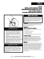
INSTALLATION INSTRUCTIONS
DIMENSIONS AND SUBMITTAL DATA
power exhaust accessory
for gravity vented gas-fired equipment
IMPORTANT
The use of this manual is specifically intended for a qualified
installation and service agency. All installation and service of
these units must be performed by a qualified installation and
service agency. Modine manuals may contain excerpts from
component supplier literature adapted for Modine products.
Any accompanying component supplier literature is for
general information.
Packaging
The power exhauster is shipped in two packages. The power
exhaust in one carton and the adapter kit for the unit heater or
duct furnace in a separate carton.
WARNING
1.
2.
Improper installation, adjustment, alteration, service or
maintenance can cause property damage, injury or
death, and could cause exposure to substances which
have been determined by various state agencies to
cause cancer, birth defects, or other reproductive harm.
Read the installation, operating, and maintenance
instructions thoroughly before installing or servicing this
equipment.
The installation and maintenance instructions in the unit
manual as well as the following instructions must be
followed to provide safe, efficient and trouble-free
operation. In addition, particular care must be exercised
regarding the special precautions listed on page 2 of the
units Installation and Service Manual. Failure to properly
address these critical areas could result in property
damage or loss, personal injury, or death. These
instructions are subject to any more restrictive local or
national codes.
CAUTION
This power exhauster (for horizontal or vertical venting) is
designed for use on gas-fired unit heaters and duct furnaces
made by Modine Manufacturing Company. The power
exhauster adapter is to be used with the power exhauster.
Do not use the adapter on any heater model other than that
specified in this manual. A restrictive type vent cap (i.e.
Breidert Type L, Gary Steel 1092) should be used when
power exhausting.
Application –
When to use this Power Exhaust
To overcome venting difficulties of gas-fired unit heaters and
duct furnaces due to:
1. Non-linear or irregular vent runs.
2. Long horizontal vent runs.
3. Negative pressure areas.
4. Low ambient temperature areas restraining natural drafts.
Available Voltages
The PV-124 power exhaust is furnished with tri-voltage
115V/208V-230V single phase motors. Each motor displays a
wiring diagram showing the wiring schematic for 115 V or
208V/230V power. When utilizing 460V 3ø power, a 250VA
transformer must be used to step down to 230V or 115V. The
power exhaust includes a 25-volt factory mounted relay for
operation with the gas unit’s 25-volt control system.
Operation
The power exhaust contains an integrally mounted motor that is
controlled by a room thermostat. When the thermostat senses
the requirement for heat, it starts the exhaust motor. When the
motor reaches proper running speed, a built-in centrifugal switch
closes; thus the automatic gas valve, which is electrically in
series with the switch, becomes energized and gas flows to the
burner. When the thermostat is satisfied, the exhaust motor
stops, centrifugal switch opens, and gas valve closes. If the
motor does not run or reach proper running speed, the
centrifugal switch will not close and the automatic gas valve will
not be energized.
THIS MANUAL IS THE PROPERTY OF THE OWNER.
PLEASE BE SURE TO LEAVE IT WITH THE OWNER WHEN YOU LEAVE THE JOB.
INSTALLATION
through holes provided in adapter flange, and fasten with two
(2) #10 sheet metal screws. The “S” type clip will hold the
bottom mounting plate flange to bottom of flue collar. Sheet
metal screws may also be used here if desired.(see figure 2.1)
For DFG/DBG/DCG/IFG/IBG/ICG, assemble adapter over
outlet collar of flue. Drill three (3) 1/8” diameter holes into flue
collar through adapter in evenly spaced intervals around
adapter. Fasten with three (3) #10 sheetmetal screws.
Power Exhauster Installation Instructions
To install the power exhaust, proceed as follows:
1. Verify that the correct adapter is to be installed on the unit. The
carton is marked with the part number suffix for reference. For
example, for a PD250 unit, the power exhauster box would be
marked with suffix C11. This number can then be found in the
following corresponding table. For a PD unit table 2.1 identifies
a part number of 5H602696C11 where the suffix is C11. The
adapter should also be checked against the adapter
dimensions listed in table 3.1 by again using the part number of
the adapter found in tables 2.1, 2.2, or 3.1.
3. Assemble exhaust over collar of the adapter. Rotate exhaust to
desired discharge position and fasten securely in place with
sheet metal screws.
4. Refer to tables 2.1, 2.2, and 3.1 for vent pipe diameter. Typically
a smaller diameter flue pipe will be used if all requirements can
be met.
2. For PD/BD/DJE/DHE/IJE/IHE, assemble adapter over outlet
collar of flue. Drill two (2) 1/8" diameter holes into flue collar
Figure 2.1 Typical Power Exhauster Installation
typical heater
ai
collar for 6" dia.
r
an dis
flue pipe or sheet metal screws
y ch
reducer
de ar
(by others)
sir ge
ed m
a
di y
re be
ct
io in
conduit box
n
(with relay on
PV-124, 224 only)
adapter
“s” clip
motor
flue collar
power venter
Table 2.1 PD/BD - Allowable Horizontal Vent Pipe Lengths for Modine Power Exhausts
Negative Pressure in a Building, Inches H2O
Model
Adapter
Vent Pipe ➀
Size
Part No.
Diameter — Inches
4
30
3H602696C1
5
4
50
3H602696C12
5
4
75
3H602696C2
5
100
3H602696C3
4
4
125
3H602696C14
5
4
150
3H602696C4
5
4
175
3H602696C4
5
4
200
3H602696C15
5
4
250
3H602696C11
5
300
3H602696C6
6
350
3H602696C7
6
400
3H602696C7
6
.00
.05
.10
.15
.20
.25
.30
.35
.40
.45
.50
.55
.60
—
—
25
65
—
—
—
5
14
19
51
11
30
14
43
17
43
—
—
0
—
—
—
—
—
—
—
—
—
12
32
3
9
11
34
13
33
—
—
—
—
—
—
—
—
—
—
—
—
—
—
—
—
8
25
—
—
—
—
—
—
—
—
—
—
—
—
—
—
—
—
—
—
0
15
—
—
—
—
—
—
—
—
—
—
—
—
—
—
—
—
—
—
—
6
—
—
—
—
—
.40
.45
.50
.55
.60
Length of Pipe in Feet
*
*
*
*
*
*
85
*
*
76
*
77
*
61
182
47
*
*
*
*
*
*
*
*
*
*
*
*
*
*
*
*
68
52
*
92
*
*
69
62
*
*
69
61
*
*
55
48
155 148
43
39
*
*
*
96
93
83
66
57
*
*
*
*
*
*
36
78
*
55
*
52
*
44
130
35
93
79
72
47
*
*
*
*
*
*
19
63
*
48
*
44
*
38
113
32
83
63
62
38
*
*
*
*
85
*
—
49
*
41
*
36
95
32
96
28
73
47
52
29
23
60
*
*
53
*
—
34
90
34
89
28
73
26
79
24
63
31
42
19
—
—
*
*
21
56
—
20
52
27
70
20
52
17
68
20
53
15
32
10
Table 2.2 DJE/DHE/IJE/IHE - Allowable Horizontal Vent Pipe Lengths for Modine Power Exhausts
Negative Pressure in a Building, Inches H2O
Model
Adapter
Vent Pipe ➀
Size
Part No.
Diameter — Inches
4
75
3H602696C2
5
100
3H602696C3
5
4
125
3H602696C4
5
150
4
200
3H602696C5
225
5
250
3H602696C6
6
300
3H602696C7
6
350
400
3H602696C7
6
2
.00
.05
.10
.15
.20
.25
.30
.35
Length of Pipe in Feet
*
*
*
*
*
44
*
*
*
*
*
39
*
*
*
96
*
33
*
*
93
86
*
28
*
*
50
77
*
23
95
*
—
64
*
17
63
*
—
58
*
12
32
95
—
49
*
0
—
—
—
40
*
—
—
—
—
31
91
—
—
—
—
21
62
—
—
—
—
—
34
—
—
—
—
—
—
—
*
*
98
*
90
98
82
86
74
74
65
63
57
52
49
40
41
28
33
16
25
—
16
—
8
—
*
*
*
*
*
87
74
60
47
35
—
—
—
*
98
88
78
68
58
48
38
28
18
—
—
—
* In excess of 100'. NOTE: Subtract 7 equivalent feet for each elbow. Subtract 8 equivalent feet for vent cap.
➀ Where 4 and 5 appear it is the customer’s choice. Typically the smaller flue pipe diameter that meets all the requirements is used.
INSTALLATION
Table 3.1
DFG/DBG/DCG/IFG/IBG/ICG - Allowable Horizontal Vent Pipe Lengths for Modine Power Exhausts
Pressure in Unit Location ("W.C.)
0.00 0.05 0.10 0.15 0.20 0.25 0.30 0.35 0.40 0.45 0.50 0.55
Model Adapter Part
Vent Pipe
size
No.
Diameter (in) ➀
Allowable Length of Vent Pipe (ft)
75
3H36369B1
100
3H36369B2
125
3H36369B3
150
3H36369B4
175
3H36369B4
200
3H36369B4
225
3H36369B4
250
3H36369B5
300
3H36369B6
350
3H36369B6
400
3H36369B6
4
5
4
5
4
5
4
5
4
5
4
5
4
5
5
6
5
6
5
6
5
6
*
*
*
*
*
*
29
92
26
83
44
*
40
*
77
*
*
*
53
*
60
*
*
*
*
*
*
*
27
86
24
78
41
*
37
*
71
*
95
*
49
*
55
*
*
*
*
*
98
*
25
80
23
72
39
*
35
*
66
*
88
*
45
*
51
*
*
*
*
*
87
*
23
74
21
67
36
*
32
*
61
*
82
*
41
*
46
*
*
*
*
*
76
*
21
67
19
61
33
*
29
94
55
*
75
*
37
96
42
*
87
*
*
*
65
*
19
61
17
56
30
95
27
86
50
*
68
*
33
85
37
95
68
*
*
*
54
*
17
55
16
50
27
86
24
78
45
*
62
*
29
75
32
83
49
*
*
*
43
*
15
49
14
44
24
77
22
69
39
*
55
*
25
64
28
71
30
94
*
*
33
*
13
42
12
39
21
68
19
61
34
88
48
*
21
54
23
59
11
35
96
*
22
68
11
36
10
33
18
59
17
53
29
74
41
*
17
44
18
48
72
*
11
34
9
30
9
28
16
49
14
45
23
60
35
89
13
33
14
36
48
*
7
24
7
22
13
40
12
37
18
47
28
72
9
23
9
24
0.60
.70
24
75
5
17
5
17
10
31
9
29
13
33
21
55
5
12
5
12
2
5
2
6
4
13
4
13
2
5
8
21
-
* In excess of 100'. NOTE: Subtract 7 equivalent feet for each elbow. Subtract 8 equivalent feet for vent cap.
➀ Where 4 and 5 appear it is the customer’s choice. Typically the smaller flue pipe diameter that meets all the requirements is used.
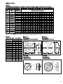
Table 3.2
Dimensional Data – Flue Adapter
Adapter No.
3H602696C1
3H602696C2
3H602696C3
3H602696C4
3H602696C5
3H602696C6
3H602696C7
3H602696C11
3H602696C12
3H602696C13
3H602696C14
3H602696C15
3H36369B1
3H36369B2
3H36369B3
3H36369B4
3H36369B5
3H36369B6
Adapter Dimensions
A
B
C
4.88
3.0
1.25
6.12
3.62
1.62
7.12
4.62
2.25
8.12
5.62
2.88
9.0
6.75
4.0
10.0
7.7
4.12
11.25
7.7
4.12
9.0
6.75
4.12
4.88
3.0
1.62
6.12
3.62
2.25
7.12
4.62
2.88
8.12
5.62
4.0
5.0
2.0
N/A
6.0
2.0
N/A
6.0
2.38
N/A
7.0
4.0
N/A
8.0
4.0
N/A
10.0
4.0
N/A
Figure 3.2
Flue Adapters
3H602696 C5-C7 and C11
Figure 3.1
Flue Adapters
3H602696 C1-C4 and C12-C15
2 HOLES IN TOP
FLANGE .219 DIA.
“C” DIA.
2 HOLES IN TOP
FLANGE .219 DIA.
“C” DIA.
.5
.5
1.75
5.88
B
D
6.88
B
INSIDE
DIM.
1.8
A
1.75
A
6.88
Figure 3.3
Flue Adapters
3H36369 B1-B3
Figure 3.4
Flue Adapters
3H36369 B4-B6
A
B
A
B
5.88
5.88
3
INSTALLATION
Dimensional Data –
Model PV-124 with 24-Volt Relay Control
5. The National Fuel Gas Code requires at least 6 inches from
combustible materials for single wall vent pipe. The minimum
distance from combustible materials is based on the
combustible material surface not exceeding 160°F. Clearance
from the vent pipe (or the top of the unit) may be required to
be greater than 6 inches if heat damage other than fire (such
as material distortion or discoloration) could result.
6. Avoid venting through unheated space. When venting does
pass through an unheated space, insulate runs greater than
5 feet to minimize condensation. Inspect for leakage prior to
insulating and use insulation that is noncombustible with a
rating of not less than 350°F. Install a tee fitting at the low
point of the vent system and provide a drip leg with a clean out
cap as shown in Figure 5.1.
Venting
WARNING
1. Gas fired heating equipment must be vented - do not
operate unvented.
2. A built-in draft diverter is provided - additional external
power exhausters are not required or permitted.
3. Gas-fired heating equipment which has been improperly
vented, or which experiences a blocked vent condition may
have flue gasses accidentally spilled into the heated space.
See unit installation and service manual for specific
information about the blocked vent safety switch supplied
on the unit.
4. If you are replacing an existing, heater, it may be necessary
to resize the venting systems. Improperly sized venting
systems can result in vent gas leakage of the formulation
of condensate. Refer to the National Fuel Gas Code ANSI
Z223.2 or CAN/CGA B149.1 or .2 latest edition. Failure to
follow these instructions can result in serious injury or death.
CAUTION
Installation must conform with local building codes or in the
absence of local codes, with Part 7, Venting of Equipment, of
the National Fuel Gas Code, ANSI Z223.1 (NFPA 54) - Latest
Edition. In Canada, installation must be in accordance with
CAN/CGA-B149.1 for natural gas units and CAN/CGA-B149.2
for propane units.
General Venting Air Instructions
1. Installation of venting must conform with local building codes,
or in the absence of local codes, with the National Fuel Gas
Code, ANSI Z223.1 (NFPA 54) - Latest Edition. In Canada,
installation must be in accordance with CAN/CGA-B149.1 for
natural gas units and CAN/CGA-B149.2 for propane units.
2. All vertically vented units with single-stage controls are
Category I. All vertically vented units with two-stage or
modulating controls are Category II. The installation of a
Category II unit must conform to the requirements from Table
4.1 in addition to those listed below.
3. From Tables 2.1, 2.2 or 3.1, select the size of vent pipe that
fits the flue outlet. Do not use a vent pipe smaller than the size
listed. The pipe should be galvanized steel or other suitable
corrosion resistant material. Follow the National Fuel Gas
Code for minimum thickness of vent material. The minimum
thickness for connectors varies depending on the pipe
diameter.
4. Vent pipes should be fitted with a tee with a drip leg and a
clean out cap to prevent against the possibility of any moisture
in the vent pipe from entering the unit. The drip leg should be
inspected and cleaned out periodically during the heating
season.
4
7. When the vent passes through an interior wall or floor, a metal
thimble 4 inches greater than the vent diameter is necessary.
If there is 6 feet or more of vent pipe in the open space
between the appliance and where the vent pipe passes
through the wall or floor, the thimble need only be 2 inches
greater than the diameter of the vent pipe. If a thimble is not
used, all combustible material must be cut away to provide 6
inches of clearance. Any material used to close the opening
must be noncombustible.
Table 4.1
ANSI Venting Requirements
Appliance
Category
Description
Venting
Requirements
I
Negative vent pressure
Non-condensing
Follow standard venting
requirements.
II
Negative vent pressure
Condensing
Condensate must be
drained.
III
Positive vent pressure
Non-condensing
Vent must be gastight.
IV
Positive vent pressure
Condensing
Vent must be liquid and
gastight. Condensate must
be drained.
8. Do NOT use dampers or other devices in the vent or
combustion air pipes.
9. Precautions must be taken to prevent degradation of
building materials by flue products.
10. The outlet of the vent should extend as shown in Figure 5.1
and Table 4.2 for vents 12” in diameter or smaller that do not
terminate within 10’ of a vertical wall or similar obstruction. For
vents larger than 12” or vents that terminate within 10’ of a
vertical wall or similar obstruction the terminal outlet must be a
minimum of 2’ higher than the vertical wall or similar
obstruction within a distance of 10’ (refer to Figure 5.2)
11. Use a vent terminal to reduce downdrafts and moisture in
vent. A vent terminal that is very open will avoid spillage at
unit’s diverter relief opening and tripping of the blocked vent
safety switch.
Table 4.2
Minimum Height from Roof to
Lowest Discharge Opening
Rise
X (in)
0-6
6-7
7-8
8-9
9-10
10-11
11-12
12-14
14-16
16-18
18-20
20-21
Roof Pitch
Flat to 6/12
6/12 to 7/12
7/12 to 8/12
8/12 to 9/12
9/12 to 10/12
10/12 to 11/12
11/12 to 12/12
12/12 to 14/12
14/12 to 16/12
16/12 to 18/12
18/12 to 20/12
20/12 to 21/12
Min Height
H (ft)*
1.00
1.25
1.50
2.00
2.50
3.25
4.00
5.00
6.00
7.00
7.50
8.00
* Size according to expected snow depth.
INSTALLATION
Additional Requirements for Horizontally Vented Category
III Units
Figure 5.1
Vertical Venting (pitched roof)➀
Listed
Terminal
X
H
Roof
Flashing
12
Roof Pitch is X/12
1/4”
Use Thimble with
Through Ceiling
1’0”
Drip Leg with
Cleanout Cap
Slope 1/4” to
the foot
1. Seal all vent joints with a metallic tape or silastic suitable for
temperatures up to 350°F. (3M tapes 425, 433 or 363 are
acceptable.) Wrap tape two full turns around the vent pipe.
2. Limit the total equivalent vent pipe length to that listed in table
2.1, 2.2, or 3.1 as it pertains to your model and job conditions,
making the vent system as straight as possible. (The
equivalent length of a 3 inch elbow is 1 foot; a 4 inch elbow, 5
feet; a 5 inch elbow, 6 feet; a 6 inch elbow, 7 feet; and a 7
inch elbow, 11 feet.)
3. The vent terminal must be a Gary Steel 1092, Breidert Type
L.
4. The vent must extend 6 inches beyond the exterior surface of
an exterior wall as shown in Figure 3b. Precautions must be
taken to prevent degradation of building materials by flue
products.
Figure 5.3
Vent Construction Through Combustible Walls
Unit
Figure 5.2
Vertical Venting (obstructed)➀
2" MIN.
Listed
Terminal
Roof
Flashing
FIBER GLASS
INSULATION
MIN. 2"
METAL
SLEEVE
10’ Min.
To wall Adjoining Building
VENT PIPE
DIAMETER
METAL FACE
PLATE
2’ * Min.
METAL
SLEEVE
1/4”
1"
45°
9"
VENT TERMINATION
SUPPORT BRACKET
(where required)
(Make from 1" x 1" steel angle)
Drip Leg with
Cleanout Cap
Slope 1/4” to
the foot
Unit
9"
2" MIN.
Use Thimble with
Through Ceiling
1’0”
1"
* Size according to expected snow depth
Figure 5.4
Horizontal Venting - Breidert or Gary Steel Vent Terminal ➀
Pitch Combustion Air
Pipe Downward from
Appliance 1/4” Per Foot
General Instructions For Double Wall (Type B) Vent Pipe
Installation:
A single section of double wall vent pipe used with a positive
pressure vent system (cat III or IV as listed in table 4.1) must
follow installation requirements for single wall vent pipe. Under no
circumstances should two or more sections of double wall vent
pipe be joined together within one positive pressure vent system
due to the inability to verify a complete seal of the inner pipes.
Multiple sections of double wall vent pipe may be used with a
negative pressure vent system (cat I or II as listed in table 4.1).
1. How to attach a single wall vent cap to double wall (type B)
vent pipe:
A. Look for the “flow” arrow on the vent pipe. Attach the vent
cap to the exhaust end of the double wall vent pipe.
B. Slide the vent cap inside the pipe.
C. Drill a hole through the pipe and the vent cap. Using 3/4”
long sheet metal screws, attach the cap to the pipe.
2. How to connect a single wall vent system to a double wall
(type B) vent pipe:
A. Slide the single wall pipe inside the inner wall of the
double wall pipe.
B. Drill a hole through both walls of the double wall pipe and
through the single wall pipe. Using 3/4” sheet metal
screws, attach the two pieces of pipe. Do not over tighten.
C. Repeat Step B drilling and inserting (2) additional screws,
evenly spaced around the pipe.
D. To seal the annular opening, run a large bead of 350°F
silastic. The “GAP” between the single and double wall
pipe must be sealed but it is not necessary to fill the full
volume of the annular area.
Terminal
6”
6"
Support Bracket
(See Fig. for Detail)
Tee with Drip Leg and
Cleanout Cap at Low
Point of Vent System
Unit
➀
Duct furnace unit shown for demonstration purposes only. Venting configuration
also applies to system units and unit heaters listed in the manual.
5
Specifications — PV-124
Blower - Wheel type, forward curved, statically balanced.
Motor
Motor type — permanent split capacitor with T.O.L.
HP — 1/9
Voltage — 115/208-230/60/1
Amps — 1.6/.8 (Fasco) - 1.7/.87 (Universal)
RPM — 3000
Sealed ball bearings
1. Built-in automatic reset, thermal overload protection.
2. Ball bearings permanently lubricated for long life.
3. Centrifugal safety switch having normally open contacts
which, when connected in series with the heater controls,
prevents burner gas flow when the power exhaust fan is not
operating.
Control System
A built-in centrifugal motor switch prevents gas flow to burner
before sufficient draft is established. The PV-124 includes a 24volt, factory-mounted, relay for operation on gas-fired units
utilizing 25V low voltage control systems.
Fan Housing Assembly
The housing and discharge flange are fabricated of steel
having baked-on electrostatically applied polyester resin
powder paint finish.
Adapter
Required to connect the power exhaust to the heater flue
outlet. Built-in restrictors are used to obtain optimum
combustion and efficiency for all size heaters.
Maintenance
The exhaust motor does not require periodic lubrication. The
bearings are permanently lubricated with a special high
temperature lubricant. A periodic cleaning of blower wheel
blades, motor, and centrifugal switch is recommended.
Electrical Connections
WARNING
1. Disconnect power supply before making wiring
connections to prevent electrical shock and equipment
damage.
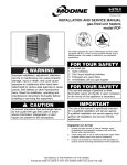
5. Connect terminal (2) of power exhaust relay to L1 of power
supply in unit junction box.
6. Connect L2 lead from power exhaust motor to L2 lead of
power supply in unit junction box.
7. Connect thermostat between terminals “T1” and “T2” of
terminal board.
Check-Out Procedure
With the power and gas supply turned off, set the thermostat to
its lowest setting.
1. If the unit has a standing pilot, turn on the gas supply only
and light the pilot according to the instructions on the unit’s
serial plate, then proceed with Step 2. If the unit is
equipped with an intermittent pilot ignition system, turn on
the gas supply to unit and proceed with Step 2.
2. Turn on power supply to unit. Nothing should happen.
3. Turn up the thermostat to call for heat. The power exhaust
motor should start, the centrifugal switch of the power
exhaust should close, and the main burner should light.
After a delay of approximately 30 seconds, the fan motor
should start.
4. Turn the thermostat down again. The main burner and
power exhaust motor should shut off. The fan motor
should continue to run for approximately 1 to 1 1/2
minutes. Modine units are equipped with a time delay
relay, and the fan motor is delayed for approximately 30
seconds on start-up, and 1 to 1 1/2 minutes on shutdown.
5. Check the power exhaust centrifugal switch for proper
function. To do this, remove the centrifugal switch lead
from terminal “V” of the terminal board. Turn up the
thermostat to call for heat. The power exhaust motor
should run, but the main burner should not light. After a
30 second delay, the fan motor should operate. The main
burner should still not light.
6. Turn down the thermostat and allow the power exhaust
motor and fan motor to stop running. Reconnect the
centrifugal switch lead to terminal “V” of the terminal
board. Recycle the unit as described in Steps 3 and 4.
If the unit does not operate in the sequence described above,
recheck all wiring until the necessary correction to the wiring
is found and corrected. Set the thermostat to the desired set
point. The unit is now ready for use.
Figure 6.1
Typical Wiring – Power Exhaust Accessory
(Modine #79858 or #79861)
2. All appliances must be wired strictly in accordance with
wiring diagram furnished with the appliance. Any wiring
different from the wiring diagram could result in a
hazard to persons and property.
3. Any original factory wiring that requires replacement must
be replaced with wiring material having a temperature
rating of at least 105°C.
To Thermostat
Terminal board
on Junction Box
T1
Installation of wiring must conform with local building codes, or
in the absence of local codes, with the National Electric Code
ANSI/NFPA 70 - Latest Edition. Unit must be electrically
grounded in conformance to this code. In Canada, wiring must
comply with CSA C22.1, Part 1, Electrical Code.
T2
F
C
V
G
To Combination
Gas Control or
Ignition Control
Typical Power Exhaust Wiring — PD/BD
1. Remove the factory installed buss bar (jumper) from
between terminals “C” and “V” of terminal board.
2. Connect one red lead from centrifugal switch (CS) of power
exhaust to terminal “C” on terminal board. Connect the
other red lead from centrifugal switch (CS) to terminal “V”
of terminal board.
3. Connect terminal (3) of power exhaust relay to terminal
“T2” of terminal board.
4. Connect terminal (1) of power exhaust relay to terminal “G”
of terminal board.
6
BL
R
R
CS
To L1
To L2
BL
1
3
2
4
Power
Exhaust
Motor
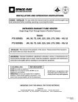
TYPICAL POWER EXHAUST WIRING - DJE/DHE/IJE/IHE
Figure 7.1
Typical Power Exhaust Wiring Models DJE/DHE/IJE/IHE
24V Relay
CS
BU
3
4
BL
POWER
EXHAUST
MOTOR
BU
1
R
2
R
All components must agree with their respective power source.
to L2
to L1
To Limit Control
(removed from T)
To Thermostat
(By Others)
H
To fan timer
(if supplied)
T
To gas valve
or ignition
controller and
fan timer (if
supplied)
Terminal board on
XFMR located on duct
furnace junction box
G
WIRING LEGEND
LINE
FACTORY
FIELD
WIRE NUT
LOW
IMPORTANT: After installing the power exhaust and adapter kit, as per instructions on front cover, and wiring the power venter per
Figure 7.1 for DJE, IJE, IHE and DHE models, use the following check-out procedure to check final installation.
Check-Out Procedure
5.
Check the power exhaust centrifugal switch for proper
function. To do this, remove the centrifugal switch lead on
limit control. Turn up the thermostat to call for heat. The
power exhaust motor should run, but the main burner should
not light.
6.
Turn down the thermostat and allow the power exhaust
motor to stop running. Reconnect the centrifugal switch
lead to limit control. Recycle the unit as described in Steps
3 and 4.
With the power and gas supply turned off, set the thermostat to
its lowest setting.
1.
If the unit has a standing pilot, turn on the gas supply only
and light the pilot according to the instructions on the unit’s
serial plate, then proceed with Step 2. If the unit is equipped
with an intermittent pilot ignition system, turn on the gas
supply to unit and proceed with Step 2.
2.
Turn on power supply to unit. Nothing should happen.
3.
Turn up the thermostat to call for heat. The power exhaust
motor should start, the centrifugal switch of the power
exhaust should close, and the main burner should light.
4.
Turn the thermostat down again. The main burner and
power exhaust motor should shut off.
If the unit does not operate in the sequence described above,
recheck all wiring until the necessary correction to the wiring is
found and corrected. Set the thermostat to the desired set point.
The unit is now ready for use.
7
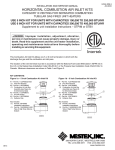
TYPICAL POWER EXHAUST WIRING - DFG, IFG, DBG, IBG, DCG, ICG
Figure 8.1
Typical Power Exhaust Wiring Models DFG, IFG, DBG, IBG, DCG, ICG with digit 13=4
CS
BL
3
4
POWER
EXHAUST
MOTOR
PE
COIL
BL
1
R
2
R
TO LIMIT
TO L2
CONTROL
R WIRE
TO L1
H
T
WIRING LEGEND
G
LINE
FACTORY
FIELD
WIRE NUT
LOW
Figure 8.2
Typical Power Exhaust Wiring Models DFG, IFG, DBG, IBG, DCG, ICG with digit 13=0, 1, 2, or 3
CS
BL
3
4
POWER
EXHAUST
MOTOR
PE
COIL
BL
1
R
2
R
91 TO L2
90 TO L1
5
6
2
WIRING LEGEND
FACTORY
FIELD
WIRE NUT
LINE
LOW
IMPORTANT: After installing the power exhaust and adapter kit, as per instructions on front cover, and wiring the power venter per
Figure 8.1 or 8.2 for DFG/IFG duct furnace and system units, use the following check-out procedure to check final
installation.
Check-Out Procedure
5. Check the power exhaust centrifugal switch for proper
1. If the unit has a standing pilot, turn on the gas supply only
function. To do this, remove the centrifugal switch lead on
and light the pilot according to the instructions on the unit’s
limit control (R) or terminal “6”. Turn up the thermostat to
serial plate, then proceed with Step 2. If the unit is equipped
call for heat. The power exhaust motor should run, but the
with an intermittent pilot ignition system, turn on the gas
main burner should not light. After a 30 second delay, the
supply to unit and proceed with Step 2.
fan motor should operate. The main burner should still not
2. Turn on power supply to unit. Nothing should happen.
light.
3. Turn up the thermostat to call for heat. The power exhaust
6. Turn down the thermostat and allow the power exhaust
motor should start, the centrifugal switch of the power
motor and fan motor to stop running. Reconnect the
exhaust should close, and the main burner should light.
centrifugal switch lead to limit control (R) or terminal “6”.
After a delay of approximately 30 seconds, the fan motor
Recycle the unit as described in Steps 3 and 4.
should start.
4. Turn the thermostat down again. The main burner and
power exhaust motor should shut off.
Commercial HVAC&R Division • Modine Manufacturing Company • 1500 DeKoven Avenue • Racine, Wisconsin 53403-2552
Phone: 1-800-828-4328 (HEAT) • Fax: 414-636-1665 • www.modine.com
© Modine Manufacturing Company 2002
1/02 - 1M Litho in USA