1
HDR 24
24/96
TECHNICAL REFERENCE
24 TRACK/24 BIT, DIGITAL AUDIO HARD DISK RECORDER AND EDITOR
HD24/96 Technical Reference
2
TABLE OF CONTENTS
FOREWORD ................................................................................................................................. 7
About This Manual/How To Use This Guide ..................................................................................... 7
CONVENTIONS ............................................................................................................................. 7
Text Conventions................................................................................................................................. 7
Window Navigation Conventions........................................................................................................ 7
HARDWARE OVERVIEW.............................................................................................................. 8
Front Panel User Interface Conventions.............................................................................................. 8
System Control Buttons .................................................................................................................................. 8
Page Left and Page Right Buttons.................................................................................................................. 8
Select Buttons ................................................................................................................................................. 8
Front Panel Display and Controls........................................................................................................ 9
Transport Controls ......................................................................................................................................... 9
Current Time Display ..................................................................................................................................... 9
Status LEDs .................................................................................................................................................. 10
Front Panel Alphanumeric Display (LCD)........................................................................................ 10
Project Information Display......................................................................................................................... 10
Menu / Status Display................................................................................................................................... 10
Rear Panel .......................................................................................................................................... 11
BNC Termination Switch .............................................................................................................................. 11
MIDI Connector ........................................................................................................................................... 11
Ethernet Jack................................................................................................................................................ 11
Accessory Slots ............................................................................................................................................. 11
GRAPHICAL USER INTERFACE (GUI) OVERVIEW ................................................................... 11
GUI Conventions ............................................................................................................................... 13
Mouse Clicking............................................................................................................................................. 13
Window and Dialog Box Paradigms ............................................................................................................ 13
Keyboard ...................................................................................................................................................... 14
GUI Track Display and Controls ....................................................................................................... 15
Project Information Display......................................................................................................................... 15
Current Time Display ................................................................................................................................... 15
Time Bar / Marker Bar Overview ................................................................................................................. 15
Time Bar ....................................................................................................................................................... 16
Song Offset ................................................................................................................................................... 16
Marker Bar and Markers.............................................................................................................................. 16
Track Area ......................................................................................................................................... 16
Track Area Scrolling Conventions ............................................................................................................... 17
Track View Controls..................................................................................................................................... 17
Zoom Tricks.................................................................................................................................................. 17
Auto Scroll.................................................................................................................................................... 17
Screen Drag (Special Scroll) Mode.............................................................................................................. 18
Track Control Area ............................................................................................................................ 18
Track Number button.................................................................................................................................... 18
Record Ready buttons................................................................................................................................... 18
Take View and Active Take Number Buttons................................................................................................ 19
Solo and Mute buttons.................................................................................................................................. 19
Track Name .................................................................................................................................................. 19
Lists Panel.......................................................................................................................................... 20
Region List.................................................................................................................................................... 20
Cue List......................................................................................................................................................... 20
Part No. 820-231-00 Rev. B 19th Jan 2001
©2001 All Rights Reserved. Mackie Designs.
HD24/96 Technical Reference
3
History List – Undo and Re-do..................................................................................................................... 21
FILE MANAGEMENT ................................................................................................................. 22
Projects and Playlists – Keeping Track of the Files .......................................................................... 22
What’s A Project?......................................................................................................................................... 22
What’s A Playlist? ........................................................................................................................................ 22
Concepts of Project Organization ................................................................................................................ 22
Project Management .......................................................................................................................... 23
Project Manager........................................................................................................................................... 23
New Project .................................................................................................................................................. 23
Open Project................................................................................................................................................. 24
Save Project.................................................................................................................................................. 24
Rename a Project ......................................................................................................................................... 24
Delete Project............................................................................................................................................... 25
Templates...................................................................................................................................................... 25
PLAYLIST MANAGEMENT ......................................................................................................... 26
Regions .............................................................................................................................................. 26
Region List.................................................................................................................................................... 26
Region Views ................................................................................................................................................ 27
Region Names............................................................................................................................................... 27
Capture Region............................................................................................................................................. 27
Importing Audio Files .................................................................................................................................. 28
Render Tracks............................................................................................................................................... 28
Purge Unused Files ...................................................................................................................................... 29
Backup and Restore ........................................................................................................................... 30
MEDIA MANAGEMENT .............................................................................................................. 31
Formatting Drives .............................................................................................................................. 31
Verify Drive Performance ................................................................................................................. 32
Mount/Refresh Drives ....................................................................................................................... 32
TRANSPORT OPERATION .......................................................................................................... 33
Transport Controls ............................................................................................................................. 33
REWIND....................................................................................................................................................... 33
FAST FWD ................................................................................................................................................... 33
STOP ............................................................................................................................................................ 33
PLAY............................................................................................................................................................. 34
Locate Points – LOC, LOC1, LOC2, LOC3, and LOC4).................................................................. 34
LOC (Transport Locate)............................................................................................................................... 34
Numbered Quick Locate Points (LOC 1, 2, 3, and 4)................................................................................... 34
Looping (LOC 1 and LOC 2)........................................................................................................................ 36
Loop Selection .............................................................................................................................................. 36
Auto Punch (LOC 3 and LOC 4) .................................................................................................................. 36
AutoPlay mode................................................................................................................................... 36
Cues ................................................................................................................................................... 37
Preroll ................................................................................................................................................ 37
Time Code Chase............................................................................................................................... 37
RECORDING OPERATIONS ........................................................................................................ 38
Record Standby and Record Ready (Arming tracks)......................................................................... 38
RECORD ........................................................................................................................................... 38
One Button Punch.............................................................................................................................. 39
Punching In ........................................................................................................................................ 39
Record Safe........................................................................................................................................ 40
Rehearse............................................................................................................................................. 40
Auto Punch ........................................................................................................................................ 40
HD24/96 Technical Reference
4
Auto Take .......................................................................................................................................... 41
Record Time Left............................................................................................................................... 41
MONITOR MODES ..................................................................................................................... 41
All Input............................................................................................................................................. 42
Auto Input .......................................................................................................................................... 42
Auto Input ON .............................................................................................................................................. 42
Auto Input OFF ............................................................................................................................................ 42
Solo and Mute.................................................................................................................................... 42
METERING ................................................................................................................................ 43
GUI Meters ........................................................................................................................................ 43
GUI Meter Ballistics – Peak and Average Modes........................................................................................ 43
Clip (Overload) Indicator............................................................................................................................. 44
Front Panel meters ............................................................................................................................. 44
EDITING OPERATIONS .............................................................................................................. 45
Track and Region Editing Tools........................................................................................................ 45
Selection ............................................................................................................................................ 45
Area Selection (I-Beam Tool) ....................................................................................................................... 45
Region Selection (Hand Tool) ...................................................................................................................... 46
Magnifier ........................................................................................................................................... 47
The Dive Key (Z)............................................................................................................................... 47
Node Tool .......................................................................................................................................... 47
Cursor Location Display.................................................................................................................... 47
Nudge Tools....................................................................................................................................... 47
Nudge Resolution ......................................................................................................................................... 47
Nudge arrows ............................................................................................................................................... 47
Selection Start (left), Selection End (right), Selection (center) boxes........................................................... 48
Scrub Wheel....................................................................................................................................... 48
Edit Clipboard.................................................................................................................................... 48
History List ........................................................................................................................................ 49
Cut...................................................................................................................................................... 49
Delete ................................................................................................................................................. 49
Copy................................................................................................................................................... 49
Paste ................................................................................................................................................... 50
Paste Repeat....................................................................................................................................... 50
Splice Mode ....................................................................................................................................... 50
Snap and Snap-to Functions .............................................................................................................. 51
Snap Enable.................................................................................................................................................. 51
Snap to Grid ................................................................................................................................................. 51
Snap to Cues................................................................................................................................................. 52
REGION MANIPULATION TOOLS AND FUNCTIONS ................................................................... 52
Split.................................................................................................................................................... 52
Crop ................................................................................................................................................... 52
Moving Regions................................................................................................................................. 52
Insert Time......................................................................................................................................... 53
Fades .................................................................................................................................................. 53
Auto X-Fade (Crossfade)................................................................................................................... 53
Volume Envelope .............................................................................................................................. 54
Region Editor..................................................................................................................................... 55
Region Name ................................................................................................................................................ 55
Start time ...................................................................................................................................................... 56
End Time ...................................................................................................................................................... 56
HD24/96 Technical Reference
5
Region Length .............................................................................................................................................. 56
Fade In and Fade Out .................................................................................................................................. 56
Envelope Active ............................................................................................................................................ 57
Region Looping ............................................................................................................................................ 57
Region Lock.................................................................................................................................................. 57
SYSTEM SETUP .......................................................................................................................... 58
General............................................................................................................................................... 58
Mouse Speed................................................................................................................................................. 58
Waveform colors........................................................................................................................................... 58
Footswitch and Footswitch Remote.............................................................................................................. 58
Date and Time .............................................................................................................................................. 58
Window Frames............................................................................................................................................ 58
FTP Server ......................................................................................................................................... 58
Digital I/O .......................................................................................................................................... 59
Locator-MMC – Tempo Map and Tempo settings ............................................................................ 59
Sync ................................................................................................................................................... 59
Sample Clock................................................................................................................................................ 59
Sample Rate.................................................................................................................................................. 59
Bit Depth ...................................................................................................................................................... 59
Time Code Source ........................................................................................................................................ 59
Time Code Frame Rate................................................................................................................................. 59
Generate MTC / SMPTE............................................................................................................................... 60
Time Code Offset .......................................................................................................................................... 60
DISK DIRECTORY ORGANIZATION ........................................................................................... 60
Project Files & Folders: ..................................................................................................................... 60
System Files & Folders:..................................................................................................................... 61
Project Files & Folders Heirarchy:.................................................................................................... 61
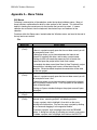
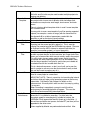
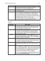
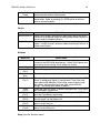
APPENDIX A – MENU TABLES .................................................................................................. 63
GUI Menus......................................................................................................................................... 63
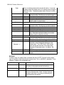
File ............................................................................................................................................................... 63
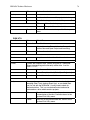
Edit ............................................................................................................................................................... 65
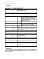
Options ......................................................................................................................................................... 67
Transport ...................................................................................................................................................... 68
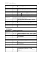
Playlist.......................................................................................................................................................... 69
Windows ....................................................................................................................................................... 69
Setup (from the Windows menu) ................................................................................................................... 69
Front Panel Setup and Utility Buttons and Menus ............................................................................ 73
DELETE LAST ............................................................................................................................................. 73
TRACK (OPTIONS)...................................................................................................................................... 73
PROJECT (FILES MENU) ........................................................................................................................... 74
BACKUP ........................................................................................................................................... 75
DISK UTIL ........................................................................................................................................ 76
SYSTEM............................................................................................................................................ 77
DIGITAL I/O ..................................................................................................................................... 77
SYNC Options ................................................................................................................................... 78
APPENDIX B – LIST OF PARAMETERS AND HOW THEY’RE SAVED ......................................... 81
Setup Parameters – What’s Saved and When.................................................................................... 81
Global Preferences............................................................................................................................. 81
Project-Based Parameters .................................................................................................................. 82
Project-Unique Parameters with Defaults for New Projects ............................................................. 82
Parameters Saved with the Project AND in the Template................................................................. 82
Parameters Not Saved with a Project................................................................................................. 83
HD24/96 Technical Reference
6
APPENDIX C – NETWORKING (FTP) SETUP ............................................................................ 84
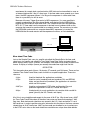
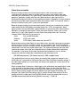
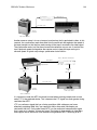
Peer to Peer Networking .................................................................................................................... 84
Required Cables and Hardware ................................................................................................................... 84
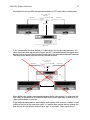
Hardware Interconnection ........................................................................................................................... 85
Computer Software Required ....................................................................................................................... 85
Network Configuration ...................................................................................................................... 85
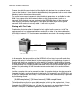
HDR24/96 Settings ............................................................................................................................ 85
Configuring the HDR24/96 FTP Server ............................................................................................ 85
System #2 Settings (second computer or other Ethernet device) ...................................................... 86
Configuring TCP/IP: .................................................................................................................................... 86
TCP/IP Is Not Listed .................................................................................................................................... 87
FTP Client Configuration .................................................................................................................. 87
Networking Glossary ......................................................................................................................... 88
TCP/IP.......................................................................................................................................................... 88
FTP............................................................................................................................................................... 88
IP Address .................................................................................................................................................... 89
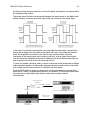
Hub ............................................................................................................................................................... 89
10BaseT vs. 100BaseT.................................................................................................................................. 89
APPENDIX D – SYNCHRONIZATION .......................................................................................... 90
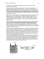
What Makes the HDR24/96 (and Other Devices Like it) Tick? ....................................................... 90
How can you Sync to Word Clock and Time Code at the Same Time? ............................................ 92
Jam Sync....................................................................................................................................................... 92
Trigger Sync ................................................................................................................................................. 93
More about Time Code ...................................................................................................................... 93
Video Synchronization ...................................................................................................................... 95
Working with Time Code .................................................................................................................. 97
A Word or Three about Pull-Ups and Pull-Downs............................................................................ 99
Safe Synchronization ....................................................................................................................... 101
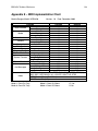
APPENDIX E – MIDI IMPLEMENTATION CHART .................................................................. 103
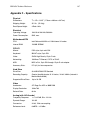
APPENDIX F – SPECIFICATIONS ............................................................................................. 104
Physical............................................................................................................................................ 104
Electrical .......................................................................................................................................... 104
Motherboard/CPU............................................................................................................................ 104
CPU I/O ........................................................................................................................................... 104
Hard Drive ....................................................................................................................................... 104
Video................................................................................................................................................ 104
Analog (with AIO-8 cards) .............................................................................................................. 104
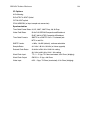
I/O Options ...................................................................................................................................... 105
Synchronization ............................................................................................................................... 105
HD24/96 Technical Reference
7
Foreword
Welcome Aboard! Thank you for choosing the Mackie Designs HDR24/96 Hard Disk Recorder - a benchmark in affordable professional multitrack audio recording. Occupying only 4U of rack
mount space, the HDR combines the familiarity of a multitrack tape recorder with a powerful,
built-in DAW-style editor.
About This Manual/How To Use This Guide
Your HDR24/96 instruction manual comes in three parts. The Quick Start Guide is intended
to help you get your HDR24/96 installed, interfaced to your console, and configured so you
can start recording quickly. The Applications Guide walks you step-by-step through the
processes of recording, overdubbing, and editing, showing you the HDR24/96’s way of
doing familiar tasks and introducing you to the power features that bring it capabilities far
beyond those of a conventional multitrack recorder.
Finally, this Technical Reference gives detailed explanations of all the controls, displays,
and menus. Keep it handy while you’re learning your way around. Here you’ll find more
detailed information on controls, indicators, and functions, files and file management, the
complexities of clocking, synchronization, and interfacing unique to the world of digital
recording. Here you’ll find some shortcuts to frequently and infrequently used features.
If you haven’t already done so, break open the Quick Start Guide, hook up your recorder,
connect the optional monitor, keyboard, or remote controller, and get rolling. This is a
hands-on process.
Conventions
Text Conventions
The following conventions are used throughout this guide:
Keyboard Keys – SHIFT, A, a
Key combinations – CTRL+SHIFT+6
Functions – Record
Names of GUI objects (buttons, arrows) or panel controls – TC CHASE
Window Navigation Conventions
This manual uses a shortcut notation that will lead you to a window in which a described
operation is performed or a parameter is viewed. The various levels leading to the desired
window are separated by a vertical bar “|”. For example: Windows | Setup | Locator-MMC
means: Select Windows from the top level menu, then Setup from that list, then LocatorMMC from the Setup dialog box.
HD24/96 Technical Reference
8
Hardware Overview
The HDR24/96 has two user interfaces. The front panel controls are designed so that you can
operate it just like any other multitrack recorder. Other than the naming of projects to assist
you with session record keeping, if you’re familiar with multitrack recorders, there are very few
unfamiliar operations. Using only the front panel controls, you can perform all of the normal
recording, playback, backup, and file management operations. There’s more to the HDR24/96
than straightforward recording, however.
Adding a standard computer keyboard and monitor brings the power of a Graphical User
Interface (GUI) to the HDR24/96. This is where you’ll find the editing tools as well as
convenience features such as named locate points for quickly jumping around within your
project.
Optional remote controllers bring the front panel controls closer to your console workspace and
add a few more features. In addition, the HDR24/96 responds to MIDI Machine Control (MMC),
so you can perform many operations from another user interface such as a sequencer or
mixing console that sends MMC commands.
Front Panel User Interface Conventions
Most of the buttons on the front panel need no explanation (don’t worry, we’ll explain them
anyway). The display (LCD) and the buttons immediately below it control the computer
that’s at the heart of the HDR24/96. Once you understand the functions, you’ll find them to
be intuitive.
Originally we plopped all of the controls onto the HDR front panel and found that after a
while, it was entirely filled with buttons. So we decided to lose a few along the way, and hide
the ones that were used less frequently (as often as you visited Aunt Sadie) somewhere
under an LCD menu. To make up for missing buttons and the need for a road map, we
stuck in a few Go Here and Go There buttons and here's what we came up with:
System Control Buttons
Most of the group of buttons immediately above the transport (“tape deck”) controls
open menus in the LCD. These are the entry points to the LCD menus and are called
System Control buttons.
Page Left and Page Right Buttons
The large < and > buttons are page navigators. If a menu consists of more than one
page, the top line on the 24 character by 4 line LCD readout will display a ← or → in the
upper left or upper right corner to indicate the direction in which you may page to find
more choices within that menu.
Select Buttons
The four SELECT buttons under the LCD are aligned under text describing the choices
available within that menu. Examples include Exit, confirmation (OK), increment or
decrement a number, scroll through choices, or advance through operational tier buttons
("follow the signs, you won't get lost"). Select buttons soft buttons whose function
changes depending on the operation you’re performing.
HD24/96 Technical Reference
9
Pairs of SELECT buttons with <<
>> displayed above them are used to select
among choices or move a cursor v through a text field. The (-)DEC and (+)INC
(decrement and increment) buttons scroll through choices in the active field. Sometimes
they duplicate the << >> buttons, and at other times, they interact, where the << >>
buttons select the character which will be changed by the DEC and INC buttons.
Pressing the SELECT button labeled “OK” in the display performs the menu operation in
process. There’s usually a button labeled “Cancel” should you decide not to complete an
operation. Pressing any menu button will also back out without performing the operation.
Front Panel Display and Controls
The (-)DEC and (+)INC (decrement and increment) buttons are used to modify an
alphabetical or numerical parameter displayed in the LCD such as Project Name or Time
Code Offset. If the red LEDs above the buttons are glowing, they’re active. Generally you
can tell that a character can be edited with the (-)DEC and (+)INC buttons if it’s sitting above
a pair of << >> characters. The Select buttons below the << >> characters move a v
cursor along numeric field, indicating which character will be changed by pressing the ()DEC and (+)INC buttons.
Any time you’re working in a menu, LED’s will illuminate above any button that does
something within that menu. Some operations, particularly those which could be disastrous
like deleting data which can’t be recovered, will offer you a Cancel option, allowing you to
quit without changing anything.
Depending on the menu and how many layers it has, Exit or Cancel may bring you back to a
previous menu or all the way back to the top. You can also leave the menu by pressing the
button that got you there (its red LED will be on to remind you where you are), or by
pressing the left < button when the ← symbol isn’t displayed. You need not completely exit
one menu before moving to another, just press another menu button to jump into a new
menu.
Transport Controls
Transport operating controls are described in detail in other sections of this manual, so
they won’t be repeated here. This section describes the front panel displays and the
setup and system function buttons located below the LCD.
Current Time Display
Current transport time is displayed in either hours:minutes:seconds:frames (SMPTE
time) or musical score position in bars:beats:ticks (BBT). If you want the BBT display, it
must be selected through the GUI. Display of musical score position is, by nature, based
on either a known tempo (default of 120 BPM) or a tempo map derived from a standard
MIDI file. Since the tools for managing tempo are only available within the GUI, we’ve
left the display section there, too.
In BBT mode, the front panel display only shows tick numbers when the transport is
stopped. When running, the Ticks field contains hyphens (- -). Leading spaces in the
Bars field are also filled with hyphens, as: - - 73:04:45. Bar numbers greater than 999
are displayed as hyphens, however the display still counts beats (01 through 04) while
the transport is running.
NOTE: Other display options of samples and milliseconds are not available on the front panel
time code display. When those options have been selected from the GUI, the front panel
displays SMPTE time.
HD24/96 Technical Reference
10
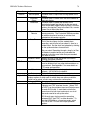
Status LEDs
The group of LEDs to the left of the time code display indicates the state of several of
the current setup options.
44.1k, 48k and 96k LEDs indicate the selected sample rate.
VARI indicates that the sample rate is controlled by an external word clock
source or video sync signal.
16 BIT and 24 BIT indicate the selected word length.
ERROR indicates a clock or synchronization error, for example, a word clock frequency
that is out of range.
TC indicates that the transport is receiving acceptable time code. This LED is only
active when the HDR24/96 is set to chase time code. The LED blinks when time code is
expected but is either not present or at the incorrect frame rate. When everything is in
order with time code synchronization, it will be on.
CLOCK indicates that a proper data clock signal is being received. It blinks if the
HDR24/96 is expecting an external clock and it’s not present. If all is well, when Internal
clock is selected, the CLOCK LED should be on.
Front Panel Alphanumeric Display (LCD)
The front panel LCD, when not performing a setup or utility operation, is an informative
summary of the current project. A screen saver blanks the display after ten minutes of
display inactivity. To re-activate it, press one of the large <
> buttons or any menu
button.
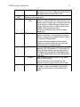
Project Information Display
The following information is displayed on the HDR hardware front panel display after
boot-up and whenever any front panel operation is exited.
PROJECT:
PLAYLIST:
DRIVE:
AVAIL:
[Name of the currently loaded project]
[The currently loaded playlist version]
[The disk drive containing the Project - Internal or External]
[The amount of recording time left on the disk]
Menu / Status Display
The LCD indicates menu choices and displays status information when a timeconsuming operation, such as disk formatting or file copy is in process. The large <
and > buttons scroll through the menu horizontally if there are more choices within the
current level menu than can be displayed in the available display area. An arrow <-- or
--> at the top corner of the display indicates that more choices are available, and in
which direction to scroll in order to view them.
NOTE: Whether or not a “Cancel” or “Exit” prompt appears above a SELECT button, it’s
okay to jump directly to one of the other top level menus without responding to a prompt.
It’s a quick “bail out” in case you’ve discovered that you’re in the wrong menu for what
you want to accomplish. Skipping an OK, Cancel, or Exit prompt will not harm or hang
the HDR24/96.
The menu table in the appendix shows the menu structure for all of the front panel setup
and utility controls.
HD24/96 Technical Reference
11
All the other controls have been addressed in the Quick Start Guide. Refer to that guide
for their descriptions.
Rear Panel
The I/O slots and connectors for the remote, footswitch, keyboard, mouse, and monitor are
explained in the Quick Start Guide. Here are a few more details about what you’ll find on the
rear panel.
BNC Termination Switch
The Termination switch on the Sync card selects whether the BNC input is bridging
(high impedance) or terminated (75 ? input impedance). Press the Termination switch in
if the HDR24/96 is the last device in the clock chain. If a clock is connected to other
devices, leave the Termination switch out and terminate the last device in the chain.
MIDI Connector
The MIDI IN and OUT ports terminate in a 9-pin D-Subminiature connector on the rear
of the MIDI Interface card. The pinout for this connector complies with the convention
used for MIDI connections to the game port of a standard sound card. The adapter from
this connector to a pair of standard 5-pin MIDI connectors is readily available at
computer stores. Some sound cards use a 15-pini D-Subminiature connector, so be
sure that you purchase the correct adapter.
Ethernet Jack
This is for connection to a 100 BaseT Ethernet network. See Appendix C for detailed
networking setup information. Note that the same connector type is used for the optional
remote controllers for the HDR24/96. Don’t mistake these two connectors!
Accessory Slots
Of course we left room for future expansion. Stay tuned.
Graphical User Interface (GUI) Overview
After plugging the keyboard, monitor and mouse into the rear panel connectors and booting up
the HDR, you'll find most of the MackieOS GUI is pretty darn similar to the rest of the
computing music world. Typical paradigms of left and right mouse clicking, menu bars with
pop-up or pull-down menus, dialog boxes, scroll bars and high resolution graphics all make for
a familiar interface.
The GUI layout is easy to learn and is designed with minimal layering of windows and functions.
The Menu bar atop the screen contains everything that can be accessed within the interface.
Mouse click on the menu item, pull down, select and release (or re-click) will kick things into
action or call up another window or dialog box. For the power users, keyboard shortcuts to most
GUI menu items are available and are listed in the menu as a reminder for next time.
Right-clicking with the mouse is context sensitive in many areas of the screen. While
everything is available with a left-click, right-clicking frequently offers short cuts to operations
you’re likely to need to perform next. While exploring the GUI, right-click and see what
happens. It’ll probably give you just the choices you’re looking for. Left click actions are usually
dictated by which one of the 4 tool choices is currently selected.
HD24/96 Technical Reference
12
The top portion of the screen contains the Tools/Meters panel and Transport Controls. The
transport control buttons will be used throughout all project operations, whereas Meters are
typically used during Tracking and Tools are typically used during Edit operations. This is why
that portion of the screen is shared between the two functions.
The Transport Control section is always visible (unless covered by a floating window) and acts
as the general location display, reading either SMPTE time code
(hours:minutes:seconds:frames), BBT (bars:beats:ticks based on the preset tempo), or, for the
serious propellerheads, time in hours:minutes:seconds:milliseconds or number of samples.
Clicking on the two graphic 'folder tabs' at the top right corner of the Tools/Meters window
selects which of the two screens is displayed.
One very handy bit of information relevant to tracking is the virtual gas gage. This tells you how
much recording time you have left on the disk and is found both in the Tools window and on the
bottom line of the HDR24/96 front panel LCD. While Editing doesn't take up much hard disk
space, tracking sure does - so take a peek at this readout from time to time to be sure you don’t
run out in the middle of the killer take. Notice that the “Time Available” follows the number of
channels you’ve selected for recording, the sample rate, and bit depth. Clever!
The major action on the GUI screen is the Tracks window, an expandable 24 track view of the
recorded regions. The tracks are bordered on the left by the 'Track Info, Record and Monitor'
panel. This contains the track numbers 1 through 24, Record Ready buttons, the virtual track
(“take”) expansion button, the active take selector, and Solo and Mute monitor buttons.
Clicking on the Take number button brings up a list from which you can select the active take
for recording or playback. Clicking on the take expansion button (→) displays the eight virtual
tracks for the selected track. Clicking it again collapses the display to the single active take for
each track.
The track display is bordered on the right by the retractable List panel. When opened with the
stubby ← at the right of the track display, the List panel displays the Regions, Cues (including
Locate points) and History List of editing operations. Clicking on the graphic 'folder tabs' at the
top of the List panel selects the displayed list. Clicking on the stubby → puts away the List
panel and extends the tracks to the full screen width.
Floating windows (normally closed and out of view) are opened from the Windows menu.
Floating windows include the multifunction Setup window, Region Editor, the Shortcut list and
the infamous About Box, which tells you what version of software you're using and who the
heck is responsible for much of this wunderbox.
If you’ve never used a GUI before, the following section explains the basics of operation of the
mouse, keyboard, and how to make selections. If you’re already familiar with computer GUI
operation, there’s nothing new here other than to remind you that clicking in the top right hand
corner closes HDR24/96 windows. A left corner click to close a window has gone out the
window.
If you’re comfortable with GUI operations, feel free to jump ahead to the good stuff about
Project Information and HDR features and functions. Otherwise, here are some GUI basics:
HD24/96 Technical Reference
13
GUI Conventions
Mouse Clicking
Left click
Most of the time when we say “click”, we mean left-click, that is, a single click of the
left mouse button when the cursor is pointing to the text or object you want to
change or move.
Text menu items are selected with a single point-and-click operation. Time fields
such as locate points and the time code display can be edited by clicking on a
numeric field and dragging the mouse pointer up or down. Alternatively, when the
field is highlighted with a single click, a direct entry can be typed in from the
keyboard. Clicking once on any button will toggle the button’s function on or off or
perform the button’s function (split, loop, etc.).
Region operations (selecting and moving) are performed with a combination of
holding the left mouse button and dragging the cursor. The operation performed
depends on the type of cursor selected.
Multiple items (for example regions or record-ready buttons) can be selected by
holding the Ctrl or Shift key while clicking. Shift-click on the first and last item in a
list selects the contiguous group of items, Ctrl-click selects multiple items from a list
which need not be contiguous.
Double clicks are usually reserved for selecting an entire word in a line of text.
Double clicking is also used to shortcut an operation without the follow-up need to
click on the specific action button (like 'Open'). For example, to open a listed project
in the Open Project window, double clicking on a Project name inside of the dialog
list opens the project and skips the need to click on the Open button.
A further fun fact is that holding the Ctrl control key and clicking on any of the four
LOC time boxes will capture the current time (the big display) into the LOC box - a
nice feature for capturing punch and loop points, even on the fly.
Right click
Right-clicking the mouse usually brings up a menu of appropriate actions for
whatever you’re doing. When the menu pops up, left-click is used to select from the
menu. For example, right-clicking on in the Current Time display brings up a menu
to select the time units. Right-click on different areas of the screen to familiarize
yourself with the pop-up menus - they are aplenty.
Double click
Double-clicking is the shortcut to select and perform the action. Most functions of the
HDR24/96 can be performed with a double-click.
Drag
Dragging is the process of selecting an object with a left-click, then moving the
object to a new location by moving the mouse while holding the left button.
Window and Dialog Box Paradigms
Much of the MackieOS windowing scheme will be familiar to personal computer users.
The Menu or title bar on an open window can be double clicked to 'window shade' the
rest of the window. This will keep the title bar of a floating window visible so it will be
handy, but clear the deck to give you a better view of your work area. Clicking and
HD24/96 Technical Reference
14
dragging the title bar allows the window to be placed elsewhere within the confines of
the screen. Most windows will float and can be condensed to only the title bar with the
exception of the 'window-like' Lists.
In some windows, you’ll find a Zoom box on the title bar which expands the window to
maximum screen size, and a resize tab (lower right hand corner) to tailor the size to your
liking.
Scroll bars with arrows and a list location scroll 'thumb' are found in list windows if the
quantity of items exceeds the current allotted window length. A Close button ( the
triangle in the upper right corner) puts the window to bed. You can also close a window
using the ESC key.
If you have more than one window open on the screen, one will be the topmost, or
“active” window. The title bar of the active window will appear solid and you’ll see the
Close button in its upper right corner. Inactive windows, whether fully open or partially
closed (“window shade”) will have their titles grayed-out. Clicking on the title bar of any
inactive window makes it the active one.
The Tab key as well as the mouse pointer can be used to navigate between fields within
the active window. Either way, when a field is highlighted, usually indicated by a
surrounding box, the field will be updated when you press the Enter key, close the
window, or click outside the window, making it inactive.
Lists
Any window that contains a list needs a selection mechanism or two. As
aforementioned, clicking on a list item selects it. After selecting on one list item,
Shift + click on another item selects those two items and all items in between. Ctrl +
click allows for selection of multiple list items. Double clicking an item is usually a
shortcut and directly performs the expected operation, such as opening a Project or
Playlist. Tab navigates between the window operation buttons; once a button is tabhighlighted, pressing the 'Enter' key performs the button’s action.
Menus
Pulldown menus are used for choosing among two or more items. Drag the mouse
pointer to the desired selection, and let of the mouse button to nail the selection.
Menus with 'depth', i.e. multiple choices leading to multiple choices, usually open
horizontally from a menu item that's tagged with a '>' indicating that you're to drag or
click on the choice to the right, which offers more choices. Intrigued?
Radio Buttons
Radio buttons are used to make mutually exclusive selections, for instance selecting
the active take within a given track (there can be only one active at a time). Clicking
a radio button turns its function on, and turns off the previously selection.
Keyboard
Tab key
Navigating between text boxes and/or time fields can also be accomplished by using
the tab key. Shift-tabbing navigates in a backwards fashion. 'Enter' is used to
complete a text or time setting entry or modification, and exits the fields as such.
HD24/96 Technical Reference
15
Shortcuts (modifiers)
Shortcuts are made up of key combinations with the shift, control, and alt keys
leading the pack for 'buddy' keys - the keys that need to pal along with pressing
some other key in order to accomplish some operation without having to click and
drag. For example, pressing the Ctrl plus the 'N' key will start a New Project
operation. See the shortcuts list in the appendix.
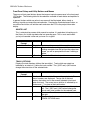
Numeric Keypad
The numeric keypad is used for quick Cue point entry and location. To jump directly
to Cues 00 through 99, type the Cue number on the numeric keypad and press
Enter. (You must enter two digits - e.g. 05 - in order to get to the cue you really
want) To jump to the next or previous Cue in the Cue List, press the + or – keys on
the numeric keypad or the regular keyboard.
GUI Track Display and Controls
The following section introduces the different areas of the GUI screen and the various
screen navigation controls. References are made to certain items with which you may not
yet be familiar such as Regions and Virtual Takes. Don’t worry, they’ll be described further
on.
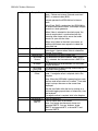
Project Information Display
The following project information is displayed in the upper right corner of the main
screen:
Drive: [Internal/External] Project Name
Version
Time
Current Time Display
The Current Time display shows the time of the current transport position in SMPTE
time (Hours, Minutes, Seconds, Frames) or in musical terms of Bars or measures, Beats
and Ticks (BBT). The displayed time is correlated with the time shown on the Time Bar
and the position of the Current Time line.
Since the transport position is ultimately related to absolute time, BBT is calculated for
the purpose of display based on a known tempo. The default tempo is 120 beats per
minute, but this can be adjusted from the Windows | Setup | Locator-MMC window. The
working tempo is stored along with the Project.
A tempo map can also be extracted from a Standard MIDI file, and the BBT display will
change dynamically to follow the MIDI file’s tempo changes. Tempo maps are loaded
from the floppy disk using the LOAD button in the Windows | Setup | Locator-MMC
window.
Units for the time display are selectable from the GUI only, from the
Options | Time Units window. A shortcut is to right-click on any time display window. A
popup menu will allow you to change units directly. This is a global change - changing
time units from ANY time display will change the time units in ALL time displays.
Time Bar / Marker Bar Overview
The strip immediately above the track area is split horizontally into the Marker (top) and
Time (bottom) bars. The Marker Bar contains graphic icons representing cues, punch or
loop points. The Time bar line contains the time scale, with major and minor divisions
spaced according to the chosen SMPTE / BBT view and/or the defined resolution.
HD24/96 Technical Reference
16
Time Bar
At the highest resolution, the display is approximately 12 milliseconds wide, or about half
a video frame. At the lowest resolution, full scale of the display is 24 hours, the
maximum recording time of the HDR24/96. The left and right arrow buttons to the left of
the time/marker bar expand and contract the track display in time. Use high resolution
when editing samples or small regions, use lower resolution to get the big picture of your
project.
Tip: Track area overviews may be stored and recalled using the F5 to F12 keys. This is
useful for jumping between high and low resolution views or switching between
displaying the single active take or multiple takes. These keys store the track zoom level
and the positioning and expansion of takes, but of course the content of the tracks
changes with editing and recording. The current track and region content is always
displayed with the parameters of the stored view. Ctrl-F(n) stores the view, F(n) recalls
the stored view.
Time selection is made by clicking and dragging the I-Beam tool along the marker/time
strip. This creates a selection area across all tracks, but does not specifically define any
regions within the selection area. Regions on individual tracks may be selected
afterwards. See Track and Region Tools for the details.
A single click on the Time bar using any one of the tools places the current time bar at
the clicked-on time and sets this time into the main transport time display.
Right clicking on the Time / Marker bar pops up a shortcut menu with choices that
include time units display, loop selection and snap-to options. All of these functions
have been described elsewhere.
Song Offset
When the HDR24/96 is set to display in BBT, the Song Offset can be used to slide the
entire time bar horizontally so that playback coincides with Bar 1. This does not affect
anything other than the time display in the Time Bar, and has no effect when the
transport position is displayed in SMPTE time.
To adjust the Song Offset, open the Setup Window (Windows | Setup or Ctrl+1) and
select Locator-MMC. The value displayed in the Song Offset window can be adjusted
by clicking and dragging on the number fields, clicking and entering a number from the
keyboard, or transferring the current time into the window by holding the Ctrl key and
clicking in the Song Offset window.
Neat Trick: To set the beginning of the song to BBT 1:1:000, set the Current Time to the
beginning of the song, then Ctrl-Click in the Song Offset window.
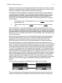
Marker Bar and Markers
The Marker Bar contains draggable icons for Cues and LOC points that serve as jumpto points in a playlist. Markers for Cues may be re-labeled, while LOC markers, since
they have dedicated functions, have fixed labels. Dragging any marker will update the
time field relevant to that marker. See the sections on Cue List, Punch, Loop, and
Recording Operations for more details.
Track Area
The track area, where all the audio action is, has three separate work areas. At the left is
the Track Control area, the center section contain the graphical display of recorded tracks,
HD24/96 Technical Reference
17
virtual takes, and regions. The right section, which can be opened or closed, depending on
what you want to see at the moment, contains the List Panel (see page 20).
Track Area Scrolling Conventions
The vertical and horizontal scroll bars that frame the track area are standard GUI tools.
Scroll thumb buttons (resembling console fader knobs) appear along the scroll bar
whenever the track screen is expanded so that there are more tracks than are visible on
the screen. Click and drag these buttons to bring another group of tracks or regions into
view.
Small + and - buttons at the lower right corner of the track area (one pair on each axis)
adjust the horizontal and vertical magnification of the track area. They duplicate the
larger arrow buttons at the left edge of the Time/Marker bar.
Track View Controls
The Zoom Arrows at the left end of the time bar are used for adjusting the horizontal
and vertical scale of the track view. When the track is expanded to display Virtual takes,
the eight takes follow the action of these buttons in the same manner as the single
(collapsed) track view.
The Up and Down arrows change the vertical magnification, resizing so that the desired
number of tracks are displayed on screen. A minimum of 2 and maximum of 24 track
spaces may be displayed. Tracks are displayed contiguously (you can’t display just
tracks 3, 8, 17 and 22), and the track display can be scrolled vertically through all the
tracks (when fewer than 24 are visible) by using the scroll button at the right end of the
track area.
The Left and Right Zoom arrows expand or contract the time scale. The horizontal
scroll button at the bottom of the display moves the tracks horizontally along the time
scale.
Zoom Tricks
The Z (Dive) key is used to perform a quick zoom at the current cursor location. It only
zooms while the key is held down.
The magnifier buttons (the small + and - buttons) on the scroll bars framing lower right
corner of the track area act in the same manner as the Zoom arrows. They are placed
for convenience and as a normal GUI windowing convention.
A keyboard shortcut to the zoom arrows is Ctrl + any of the keyboard arrow keys.
A keyboard shortcut to the scroll buttons is the Alt + any of the keyboard arrow keys.
The Magnifier icon in the Tools panel changes the cursor into a magnifying glass. This
Magnifier cursor can be dragged over the area of interest to zoom in to a highly detailed
view of a small area.
Auto Scroll
When Auto-scroll is enabled, the current time line jumps to the center of the screen and
the tracks scroll behind it as the transport plays. When disabled, the track area remains
fixed on the screen and the current time cursor moves along the tracks as the transport
plays. At lower resolutions, with Auto-Scroll off, when the current time cursor reaches
the right edge of the screen, it jumps back to the left edge, the track area jumps one
screen width, and the cursor makes another sweep. At high zoom resolution, the cursor
HD24/96 Technical Reference
18
will play off screen and remain out of view. The Auto Scroll button blinking indicates that
a zoom level has been selected that the auto-scroll function cannot track.
Screen Drag (Special Scroll) Mode
Holding the D key down when the cursor is in the track area temporarily changes the
cursor into a hand icon with which to drag the screen in any direction, to the extent of
the minimum or maximum axis values. This time-saver can be used to pull the screen
view omnidirectionally rather than using the scroll bars, which move the screen area
under the cursor in one axis direction only.
Track Control Area
The Track Control area, the portion to the left of the main track area, includes the following
controls and indicators:
Track Number button
Tracks are numbered 1 through 24. Clicking on a track number button (or the track
itself) activates that track for editing operations and illuminates the track number button.
Multiple tracks can be enabled by clicking with the Shift and Ctrl keys as described
previously.
When a selection area is made by dragging the I-Beam Tool over the Time bar, initially
all track number buttons are illuminated. Clicking on a track number button activates the
selection area for that track and deactivates the remaining track number buttons. The
selection area can be applied to other tracks by Ctrl- or Shift-clicking on their track
number buttons.
Double-clicking on a track number button with either the Hand or I-Beam tool selects the
entire track.
A Paste is performed on the track with the illuminated number button.
IMPORTANT: If multiple track number buttons are illuminated, the Paste is performed
on the lowest numbered track of the group.
Tip: The active take on multiple tracks may be changed by first selecting a group of
tracks. Use the I-Beam tool and Ctrl-click on each track or Shift-click to select a range
of tracks. Then Ctrl-click on the take number button on any of the selected tracks to
make that the active take on all the tracks in the group. Handy when you have 10 tracks
of drum kit overdubs.
Record Ready buttons
The red R is the track arming button, which enables tracks for recording. These buttons
on the GUI screen correspond directly to their counterparts on the HDR24/96 front
panel. Clicking on an R button arms the track for recording. The button blinks until the
transport is placed in the Record mode, either by clicking on the RECORD button in the
GUI transport control area, or by pressing the PLAY and RECORD buttons on the front
panel.
As with the front panel controls, you can also start recording on a track by clicking on
the master RECORD button, then clicking on the individual track’s R button.
NOTE: If the record controls don’t operate as expected, Record Safe may be enabled.
HD24/96 Technical Reference
19
Take View and Active Take Number Buttons
The Active Take is the one that you’ll hear in playback or to which you’ll record. Since
only one virtual take can be active at a time, the number displayed in the Active Take
button indicates which of the eight takes is currently active. Clicking on a track’s Active
Take button pops up a list box allowing you to select the active take. The number within
the button changes accordingly to match the selected take.
The Take View and Take Number buttons work hand in hand. When clicking on the
Take View button, the track expands downward so that all takes are displayed. Clicking
on a take’s ACTIVE button makes that the active take. Each take has the boring default
name of “Take ‘n’”, but this can be modified by clicking on the yellow Take Name field
when the takes are visible on screen.
When the virtual takes are expanded, the Take Number button to the left of the ACTIVE
button functions in the same manner as the Track Number button. For example, clicking
on a Take Number button selects that Take as the destination for a Paste operation.
When collapsing back to the one-take-pre-track view, the currently selected active take
is displayed in the track region.
Note: The active take selection is only updated when the transport is stopped. You can’t
jump among takes on the fly.
Tip: The active take on multiple tracks may be changed by first selecting a group of
tracks. Use the I-Beam tool and Ctrl-click on each track or Shift-click to select a range
of tracks. Then Ctrl-click on the take number button on any of the selected tracks to
make that the active take on all the tracks in the group. Handy when you have 10 tracks
of drum kit overdubs.
Solo and Mute buttons
Track Solo and Mute (the S and M buttons) are output monitor functions. Mute turns off
the output of the selected track. Solo mutes everything but the selected track. Clicking
on these buttons activates the function and highlights the button. Note that when one
track is placed in Solo, all the other tracks are placed in Mute. These are toggle buttons
- click them to turn the function on or off. See the Monitor section (page 41) for further
details.
Track Name
The rightmost field in the Track Control area contains the name of the track. Default
names out of the box are simply “Track N”, where N is the track number. Tracks can be
renamed using conventional text entry procedures - click and type, then press the Enter
key or click outside the field to complete the entry.
Regions within a track inherit the name of the track at the time they are recorded. If you
label a track “Lead Guitar” before you record the lead guitar part, its regions will carry
that name. If you record with the name “Track 19” and then think to change it afterward,
your initial lead guitar recording (that’s always the one that’s the best) will have a
number, not a name.
Your pet track names can be saved as a template using the
File | Save as a New Template
command from the main menu. Once a template is saved, the next time you open a new
project, its tracks will carry the saved names. This is a useful feature if you regularly
HD24/96 Technical Reference
20
record the same tracks (name them for your band members or instruments) or are
creating a new project for each song in a live session. If you work on a variety of
projects, however, you’ll probably have different track names for every project, so you
might as well retain the old, boring defaults and enter new names as you work.
Lists Panel
The List panel is opened and closed by clicking on the List View arrow at the right end of
the Time/Marker bar, by selecting one of the three lists from the pull-down Windows menu,
or by using the keyboard shortcuts:
Regions List = Ctrl-4
Cues List = Ctrl-5
History List = Ctrl-6
Whenever the list panel is open, clicking on one of the three tabs at the top of the panel
selects which list is displayed.
Region List
The Region List contains a listing of the region names that have been created by the
following operations:
Recording into tracks
Capturing regions on existing track regions
Importing regions into the current project
Rendering tracks
Cue List
The Cue List is a list of all cues set in the Project. The three columns of the list are the
Number, Name, and Time. Clicking on the NEW button at the top of the list creates a
new cue at the current transport time. Double clicking on a cue number jumps the
transport current time to the time of that Cue.
Cues are numbered sequentially as they’re entered, and have the default name “Cue”.
Cues can be renamed within this list by double clicking on the name field and entering
new text. The time (location) of the cue can be edited by clicking on the time field,
highlighting the digits you wish to change, and either dragging the number with the
mouse pointer or directly entering a new number from the keyboard. Pressing the Enter
key or clicking outside the field completes the entry.
Cue names and times are interactive with the Cue pointers on the Marker Bar. When a
cue name is edited in the Cue List, its name changes on the Marker Bar. When the Cue
time is edited in the Cue List, the pointer on the Marker Bar moves to the new location.
When a Cue pointer is dragged to a new location on the Marker Bar, its time changes in
the Cue List.
Cues appear on the list in order by time. As you drag a cue pointer along the Marker
Bar, you’ll see its time change in the Cue List, and the entry will move up or down the list
if its new time places it past or before another cue.
Clicking on the DELETE button removes the highlighted cue from the list. This leaves a
hole in the cue number sequence, but the Cue List doesn’t care. Use Shift-click or Ctrlclick to highlight a group of cues to be deleted.
HD24/96 Technical Reference
21
RENUM(ber) changes all the cue numbers so that they’re sequential with increasing
time and contiguously numbered (no missing numbers as a result of deleted cues).
Despite the ominous warning message which appears when renumbering the cue list,
LOC points are not affected by this operation, nor are cue names or times changed.
STORE changes the time of the currently highlighted Cue to the current transport time.
This is an alternate to editing the time field or dragging the cue pointer. It’s handy if your
habit is to always use the same cue number to jump to your current working section of
the project. When you move on to work on a new section, just highlight your “working”
cue and click on STORE.
History List – Undo and Re-do
The History List is accessed by clicking on the HISTORY tab at the top of the List
window. The history list stores each editing operation while a project is open. As you
split, copy, paste, move, or record a new region, the operation appears on the list.
In addition to providing information about the progress of the editing session, the History
List lets you regress back through edits in the currently active Playlist. Clicking on any
item in the list “undoes” all the region operations that follow it on the list and bring you
back to that former edited state.
History List Caveats:
The History List is only active for the current Playlist while you’re in the process of
building it. Once another Playlist or Project is opened, the History List is purged . . .
history.
As long as you are moving among contiguous editing operations on the history list, you
can re-do anything that you’ve undone. The entries on the History List below the point to
which you’ve returned change to a gray background color, but are still on the list. If,
however, you move back up the History list (undoing some operations) and then perform
an edit operation, the following “grayed out” operations are removed from the History
list.
If you back up in the History list to an event between the last recording pass and a prior
recording pass, you’ll get a warning on the screen asking if you want to delete the audio,
and reminding you that you can’t undo that operation. Clicking “Yes” in the dialog box
will undo both the edits and the recording. This is functionally equivalent to pressing the
DELETE LAST button on the front panel or remote. Once you do this, all the operations
including and beyond the recording pass disappear from the History List.
You can, however, click “No” in the warning dialog box, and the operations, including the
recording pass, will be undone (and become grayed out on the History list), and the
audio will not be lost. Those edit operations, including the recording pass, can be redone by moving back down the History List, as long as you don’t perform another edit
operation or recording pass.
The History List is interactive with the Undo and Redo commands accessible from the
top level Edit menu or keyboard shortcuts:
Edit | Undo = Ctrl-Z
Edit | Redo = Ctrl-shift-Z.
Performing an Undo command backs up one entry on the History List, Redo moves
down one entry. See the section on Region Editing Tools for more about the History
List.
HD24/96 Technical Reference
22
File Management
Projects and Playlists – Keeping Track of the Files
What’s A Project?
A Project contains all the audio that you’ve recorded while that project name is active. It
also contains all the Playlists for that project, as well as housekeeping data such as
sample rate and bit depth.
What’s A Playlist?
A Playlist is a road map for playback of all the audio files recorded for a project. It can
be straightforward track playback, or incorporate edits and decisions as to which take, or
combination of takes, you wan to hear. You can create several versions of a project,
each with its own Playlist.
Concepts of Project Organization
If you’ve had experience working with tape-based recorders, you’ve probably just written
the name of the CD, band, or artist on the tape box and track sheets and that’s that.
Since the HDR24/96 can store considerably more material on its disk drives than would
fit on a reel of tape, you may want to organize your “big reel” differently, depending on
your working situation.
Many people new to hard disk recording are intimidated with file names, directories
folders, and the like. It’s common at first to be uncertain as to when you should create a
new project or version, but at the user level (that’s you) it’s really pretty straightforward.
The way you work will lead you in the right direction. We can’t anticipate every situation,
but here are some hints that will help you make reasonable decisions.
Before we get on with a detailed explanation of disk files, you should know that there are
automatic defaults built into the HDR24/96 that will let you ignore any of this
computerese, push the buttons, and go. While every project needs a name, the
HDR24/96’s operating system will automatically assign a unique and workable name
each time you start a new project. You’ll want to keep track notes on paper as you
would with tape, but until you recognize the benefits of a more structured approach, you
needn’t be saddled with details. The Quick Start and Applications Guides explain how to
create and manage Projects and Playlists, so we won’t repeat the details here.
Following are some examples of Projects and Playlists for you to consider.
If you’re working on an album of songs, it’s logical to envision the disk (either internal or
external) as a reel of tape, one that’s probably long enough to contain the whole album.
One approach is to simply have a single Project name for the entire album, separating
the songs by their starting time, just as you would do with tape. Cues are stored along
with the Project, so you can easily navigate from song to song by hopping among cues.
The disadvantage to this approach is that each time you back up the Project (and you
should!) you’ve backing up a lot of data, more and more as you add more songs, more
tracks, or more overdubs. That takes time.
Another approach is to make each song a new Project. It’s a little more housekeeping
work (though Templates simplify it by giving you most of the setup defaults) but shorter
Projects mean less new data to back up. Having one Project per song makes it
HD24/96 Technical Reference
23
convenient to back up a single song on a removable Mackie Media PROJECT
removable cartridge, or hand off a song to your bandmate who has an HDR24/96 so he
can add his tracks to it.
If you’re recording commercials, you may wish to create a new Project for each client
and make each commercial a Playlist. Now you can quickly pull common audio
material for that client, for instance a music bed, jingle, or sound effect, into a new
Playlist and add the voiceover with this week’s used car specials to it.
If you’re recording a concert, you probably won’t have time between songs to set each
one up as a new Project. If you want to divide the concert up into songs for production,
you can pull those into Playlists later on.
If you’ve been working on a project and put it away for the night, the HDR24/96 wakes
up with the name of the project you were working on just before shutting down. If you’re
starting out with a new or freshly formatted hard disk, the default project name Startup
will appear. If the HDR24/96 knows you were working on a project but can’t find it - for
example, it was on an external hard drive which you’ve removed, it won’t panic (though
you might!), it’ll boot up with the default Startup project name.
The name of the current Project and Playlist is shown on both on the front panel
alphanumeric display and the GUI screen.
Project Management
Project Manager
The Project Manager is a GUI utility for deleting, renaming, or backing up projects.
These functions can also be performed from menus opened with the front panel
PROJECT and BACKUP buttons. The following project management operations can be
performed from either the front panel or the GUI Project Manager.
New Project
New Project creates a new Project. The new Project inherits some if its settings (such
as Sample Rate and Time Code Frame Rate) from the current Project, and others from
the Project Template (such as Track Names and Snap settings). For information on
which parameters are inherited from the current Project and which are inherited from the
Template, see Appendix B.
To create a new Project from the front panel:
If the Active Drive (Internal or External, shown on the front panel display) is not the
drive you want to create a new Project on, press Disk Util and select Set. Change
the Active drive using the Select Active Drive menu, then select OK.
With the desired drive Active, press Project and then select New. If you have made
changes since the last Save, the HDR24/96 asks if you want to save the currently
open Project. Press No to discard the changes, press Yes to Save them. Enter the
name of the new Project and select New.
To create a new Project from the GUI:
Select New Project from the File menu or use the keyboard shortcut CTRL+N. If you
have made changes since the last Save, the HDR24/96 asks if you want to save the
currently open Project. Click No to discard the changes, click Yes to Save them. In
HD24/96 Technical Reference
24
the New Project dialog box, select the drive you want to create the Project on from
the Drive Select list box, then type in the Project name and click New.
NOTE: You cannot use the following characters in Project names: / \ : * ? “ < > | .
They are reserved for use by the system.
Open Project
Open Project opens an existing Project that has previously been saved on disk. When
the HDR24/96 boots up, it automatically opens into the last Project that was Saved
before you powered down. If the Project that was last Saved is not present when the
HDR24/96 is powered up, then the HDR24/96 creates or opens a project called Startup
on the active drive. The name of the currently open Project appears on the top line of
the LCD display, and in the space above the GUI Current Time display.
To open a Project from the front panel:
If the Active Drive does not contain the Project you wish to Open, press Disk Util and
select Set. Change the Active Drive to the desired drive from the Select Active Drive
menu, and select OK. Otherwise, press Project and select Open from the Project
Files Menu. Select the Project you wish to open from the list, then select Open.
To open a Project from the GUI:
Select Open Project from the File menu, or use keyboard shortcut CTRL+O. In the
Open Project dialog box, select the drive that the Project resides on from the Drive
Select list box. Then click on the desired Project name and click Open, or simply
double-click on the Project name.
Save Project
Saving a Project stores all changes that have been made in a Project since the last
Save operation. This includes changes to Track and Region names, Playlist Regions
(edits), Cue and Locate points, and Project preferences and settings. At the end of
every Record pass the HDR24/96 automatically saves the and newly Recorded Regions
and the Project file, so that you need only to manually Save the changes you have made
while editing.
Save operations do not clear the History List. Therefore it is possible to Save the Project
in its present state, and later on revert to a state that existed prior to Saving.
To save the open Project from the front panel:
Press the Project button. From the Project Files menu select Save.
Press the Project or Page Left (?) button to exit.
To save the open Project from the GUI:
Select Save Project from the File menu.
Or
Use the CTRL+S keyboard shortcut.
Rename a Project
Renaming a Project changes the name of both the Project file and Project folder. The
same rules of valid characters and length apply for Renaming Projects that apply to
naming new Projects.
To Rename a Project from the front panel:
HD24/96 Technical Reference
25
If the Active Drive does not contain the Project you wish to Rename, press Disk Util
and select Set. Change the Active Drive to the target drive from the Select Active
Drive menu, and select OK.
Press Project and then Page Right one screen. Select Rename. Using the
<< and >> Select buttons, choose the Project you wish to Rename and Select Ok.
Use the Select buttons to move the cursor over each character in the file name, and
use the (-)DEC and (+)INC buttons to scroll through the characters. When you have
finished Renaming the Project, select Ok to confirm.
To Rename a Project from the GUI:
Select Project Manager from the Edit menu, or use keyboard shortcut CTRL+B. In
the Project manager dialog select the Project to be Renamed. Type the new name
into the Ask Name dialog box, and click Enter when done.
Delete Project
Deleting a project permanently removes the Project file folder, all recorded, imported,
and rendered audio files, Playlist data, and waveform cache files from the hard disk.
This is the end of the line. You can’t recover a deleted project.
To delete a project from the front panel:
If the Active Drive does not contain the Project you wish to Delete, press Disk Util
and select Set. Change the Active Drive to the target drive from the Select Active
Drive menu, and select OK.
Press Project and select Delete. Choose the Project you wish to Delete from the
Delete Project Menu using the << and >> SELECT buttons. Select Del. Select OK
to confirm the deletion or select Cancel, have a latte, and think about it a while
longer.
To delete a project from the GUI:
Select Project Manager from the Edit menu, or use keyboard shortcut CTRL+B. In
the Project manager dialog, select the Project(s) to be Deleted and click Delete.
Confirm or Cancel in the “Are you sure?” dialog box.
NOTE: You cannot Delete the open Project; you must open a different Project first even
if it means first creating a new project.
Templates
The Project Template is a file that saves Project parameters. Use Templates as a
timesaver to recall frequently used Project settings when creating new Projects. When
you create a new Project, the new Project inherits the parameters saved in the
Template. Conversely, when you save the Template, the Template inherits the
parameter settings of the open Project.
Some of the parameters saved to the Template include Track Names, Time Units, and
the Snap button Snap Grid settings. Not all Project settings are saved in the Template.
For information on which parameters are saved to the Template, and the factory Default
Template settings, see Appendix B.
To save current project parameters to the Template (GUI operation only):
From the File menu, select Save As New Template. Click OK in the Confirm New
Template dialog box.
HD24/96 Technical Reference
26
To reset the Template to the factory defaults (See Appendix B for the default
settings):
From the File menu, select Reset Template. Click OK in the Confirm Reset
Template dialog box.
Playlist Management
Regions
A region is a graphic representation of an entire audio file or a portion thereof. A region
contains editable start and end boundaries (or borders) which define the start and end times
of the audio file for playback and looping purposes.
A Playlist is a list of regions within the project, with the start and end times of each region or
portion of a region that has been selected for playback. Thus, the Region is the
fundamental unit for recording, playback, and editing. Regions are what we hear when we
play our recording.
Whenever a recording pass is first made, a region is created which includes the entire audio
file. A region may be trimmed to represent only a portion of the audio file for playback by
defining new start and/or end points. Region boundaries can be modified by sliding their end
points, or new regions can be created by cutting, copying, or pasting sections of a
recording. Some of the tools and procedures have been described in previous sections.
Since the region boundaries are merely pointers as to what portion of the original recording
to play, any region can always be expanded all the way back to the original size of the
complete audio file from which it was derived.
Regions are represented on screen either as solid colored blocks (View Waveforms OFF) or
with waveform representations drawn within the blocks (View Waveforms ON), as selected
from the Options menu. The region's name appears in the upper left corner of the block,
provided the screen resolution is high enough to display the text. The name also appears in
the Regions list. The region name originally inherits the track name followed by the “take”
number, a sequentially numbered recording pass on that track.
Other graphics representations within a region boundary include fade curves, region loop
points and the volume level envelope.
Region characteristics can be viewed and modified from the Region Editor, which will be
discussed in detail further on (page 55).
Region List
The Region List is a list of all recorded passes, imported audio files, captured regions,
and rendered tracks within a Project. It represents the library of recordings on disk. Note
that only recordings are placed on the Region List, not segments of a Region that have
been split up for editing purposes. Even if you have deleted a region from a track, it’s
still on the region list, so you can easily recover it.
This list is in alphabetical order, so naming your tracks will make it easier to identify the
contents of the listed regions.
A region can be placed on to a track by clicking on its name in the Region List and
dragging it into the Track Display area and on to the desired track.
HD24/96 Technical Reference
27
A region in the Region List can be renamed by double clicking on its name field and
typing the new name. This does not automatically change the name of that region in the
Playlist (the track area), however, when a renamed region is dragged from the Region
List on to a track, it will carry the new name.
Hint: If you want to give a region both on the Region List and in the track area the same
name, you can use the keyboard Copy (Ctrl-C) and Paste (Ctrl-V) commands to carry
the new name (on the clipboard) from the Region List to the Name field in the Region
Editor.
Enter a new name in the Region List, and with it highlighted, press Ctrl-C to copy it
to the clipboard.
Double click on the region in the track area to bring up the Region Editor.
Double click on the Name field in the Region Editor to highlight it.
Paste the name from the clipboard to the Region Editor by pressing Ctrl-V
NOTE: Edit functions such as copying and pasting, or drag-copying regions will create
new regions within the track area but those do not get placed on the region list since
they are already there as part of other regions.
Region Views
Regions caught in the act of being recorded are drawn as red rectangles, but are shortly
transformed into either the waveform display or solid filled rectangular blocks after
recording has ceased (see Waveform views). The various visual shades of unselected,
selected, locked, and cross-faded regions will become apparent to you after working
within the track area for a few minutes or a day.
Locked regions change to a dark gray background and must be unlocked using the
Region editing tools before they can moved or edited.
Region Names
Regions are automatically named upon creation using their original track name. You
can rename both a region and a track, but renaming a track after a region has been
created does not automatically change the region’s name to the new track name. The
link between track and region names exists only when the region is originally created.
Because of this, it's usually good practice to name your tracks before you begin
recording if you want to be able to identify regions easily for editing purposes. If you
have a standard track layout, for instance, you’re recording several sessions with the
same band, you can save your track names as a Template using the
Files | Save As New Template
command.
Double-clicking on a region with the Hand tool pops up the Region Editor dialog box,
where you can rename the region. Note, however, that when renaming a region, its
original on the Region list does not automatically get updated. Don’t get confused.
Capture Region
The Capture Region command creates a new audio file (and therefore a new Region)
from a portion of an existing Region. Use the I-Beam tool to select an area of a region
for capture, then select Capture Region. You will be prompted to enter a name for the
captured region. When capture is complete, the selected area will appear on the Region
List and can be dragged into the current project, or imported into another project.
HD24/96 Technical Reference
28
This is a convenient way of managing a section of a song that you wish to use in
multiple places. It differs from copying a region in that it does not use the clipboard, and
it makes a permanent copy of the selected area as an audio file.
Capture Region doesn’t work across region boundaries in the Playlist but it carries fades
and volume envelope changes that have been applied to it. The selected area must be
from a single region. If you have an edited section, for example a composite vocal track,
which you want to handle as a unit, use the Render Tracks command to create a single
region from the edited section.
Capture Region is accessed from the Edit pulldown menu, or with the keyboard shortcut
Ctrl-R.
Importing Audio Files
In the HDR24/96, Recorded Regions are directly accessible only from within the Project
in which they were originally recorded; you cannot see or directly access another
Project’s Region List. To make audio from another Project available for use in the
currently open Project, you must Import the audio files into the Project. When you import
an audio file, the HDR24/96 places a copy of the source file in the Project’s Imported
folder to keep the original recorded audio intact and safe from deletion if you delete or
purge another Project. Imported audio files appear in the Regions List with their original
long file names. If multiple copies of the same source file are imported, the names of the
duplicates are appended with numbers (1,2, etc.).
You can import both mono and stereo interleaved WAV and AIFF files. When an AIFF
file is imported it is automatically converted to a WAV file. Stereo interleaved AIFF and
WAV files are converted to two mono files.
To Import audio files into the open Project (GUI operation only):
Select Import Audio Files from the File menu, or use keyboard shortcut ALT+I.
Select the drive on which the Project from which you wish to import files resides. The
Location list box will display the drive letter, and the list box will display the names of
the project folders on that drive. If you’re importing files from a Mackie Media
PROJECT drive and have changed cartridges since booting the HDR24/96, you will
need to click on the REFRESH button in order to view the directory of that disk.
Double-click on the Project name to open its folder. You will probably be importing
from the AudioFiles 1 folder, so double click on that to display the list of files.
The File Types list box is a list display filter, allowing All file names, only WAV files,
or only AIFF files to appear on the list. If you’re working with HDR24/96 files, they’re
all WAV, so you’ll see nothing if you select AIFF.
Use the Location arrow and list box to navigate up and down the HDR24/96 directory
tree, and locate the folder containing the files you wish to import. Select the source
file(s) from the file list, and click Open. You can import WAV and AIFF files at the
same time.
Render Tracks
The Render Tracks command is the functional equivalent of playing an edited track and
re-recording it so that it becomes a single region rather than a group of sequential
regions on a Playlist. Rendering includes all fades, crossfades, and volume envelope
changes. Rendering can simplify handling of a project by replacing a track with a lot of
complex edits with a single, contiguous file. Rendering is also useful when transferring a
HD24/96 Technical Reference
29
Project’s tracks to another system. Because tracks rendered as a group create regions
all having the same start and end times, by aligning the start of each file with a common
marker, tracks can be kept synchronized.
A Rendered track is placed in the Project’s Rendered file folder (see page 60) and on its
Regions List, and it can be dragged from the Regions List into the project track area,
imported into another project, or exported to a workstation. When exporting files for
further processing, Rendering all edited tracks, then exporting the rendered files
assures that tracks will be transferred with all edits intact. For compatibility with other
systems, tracks can be rendered either as WAV or AIFF files.
From the Render Tracks dialog box, you may choose to render all tracks or selected
tracks, and the start and end times of the rendering operation. If you select a portion of
a track or tracks using the I-Beam tool, the start and end times default to the area
selection times. If no area selection is made, default start time for rendering is the time
of the first recording in the project, usually around 0:00:00:00. Default end time is the
end of the last region in the displayed Playlist. These defaults will assure that the entire
song will be rendered. Start and end times can be edited in the dialog box by any of the
standard time field editing methods should you wish to render a shorter portion of the
track.
Rendered tracks inherit their current track names when they’re placed on the Region
List and in the Rendered folder, with “_RenderN” appended to the track name. N is the
number (starting with 1) of rendering operations performed with that track name.
Rendered tracks can be renamed in the Region list or, when dragged into a track, by
using the Region Editor.
The Render Tracks command is accessed from the Edit pulldown menu. There is no
keyboard shortcut. Select the track(s) or portions of a track to be rendered, select the
output file format, and click on OK. If you select AIFF format for rendering, the rendered
file will be saved in the Project’s Rendered folder, but since it is not in the HDR24/96’s
native WAV file format, it will not appear in the Region list. Should you wish to use a
rendered AIFF file in a project, you may Import it (see page 28).
Purge Unused Files
The Purge Unused Files utility compares the contents of the Project’s AudioFiles folder
with the Project’s Playlists, and deletes any audio files which do not appear on any
Playlist for the Project. This is a cleanup tool used to recover some disk space after
you’ve recorded several takes and decided that there are some definite non-keepers.
Purge works both on originally recorded audio files and rendered files.
Bear in mind that if you’ve used even the tiniest bit of a take in an edit, the entire take is
exempted from the Purge operation. If you want to economize on disk space and have
heavily edited tracks, Render those tracks, replace the edited track with the Rendered
version, and then allow the original tracks to be purged.
To Purge Regions from the Project (GUI operation only):
Select Purge Unused Files from the File menu. The Purge Audio dialog box
appears, asking whether you want to clear the History list and Save the Project
before proceeding with the Purge.
Selecting No preserves all of the recording and editing you have done since you last
Opened (or Purged) the Project and purges only Recorded Regions that were not
present in the Playlist at the time the project was Opened.
HD24/96 Technical Reference
30
Selecting Yes clears the History list and Saves the Project, allowing you to delete all
Recorded Regions not present in the Playlist.
Selecting either Yes or No brings up the Purge Current Project dialog containing a
list of all Recorded Regions slated for Purge. Click OK to delete all the Regions in
the list, or select the specific Regions you wish to Purge, then click OK.
Backup and Restore
Backup and Restore operations consist simply of copying a Project from one disk drive to
another. When a Project is Copied, the Project folder and all its contents are copied to the
target medium completely unaltered – no data compression or compacting. Projects copied
to disk drives verified for real-time recording can be opened immediately, though copies to
drives designated as Backup (PROJECT media and slower hard drives) must be copied
back to real-time drives in order to be opened for either playback or recording.
You can’t copy a project to the disk on which it currently resides – source and destination
drives must be different. If the destination drive doesn’t have enough free space to contain
the selected Projects, you’ll get an error message before the copying starts.
Backup strategies are discussed in the Applications manual. Choose yours intelligently. A
Copy operation can be either a Backup or a Restore, depending on what you’re doing. The
operations are the same going in either direction.
If you move other project-related files, such as session notes or mixer automation data into
the HDR24/96 Project folder via FTP transfer through a network, those will be copied along
with the normal contents of the Project folder when you back up to another disk drive.
To Backup or Restore a Project From the front panel:
Press the BACKUP button. Select Set Source to set the drive the Project is to be copied
from, and Set Dest(ination), the drive where the backup copy will go. Select Ok to get
back to the Backup menu.
Select Backup. Select the Project name to back up using the << and >> buttons.
Select Ok to begin the copy, or Cancel to quit without copying.
To Backup or Restore from the GUI:
Select Project Manager from the Edit menu, or use keyboard shortcut CTRL+B. This
brings up the two-pane Project Manager dialog box. Click on the Project you wish to
copy and drag it to the opposite pane in the Project Manager window. You can also click
on the Project name to highlight it, then click on the arrow pointing to the opposite
window.
Note: If file sizes are not displayed, clicking the Refresh button will bring them up.If
you’ve swapped Mackie Media PROJECT disks, their files may not be visible. Click
Refresh to update the file list.
A VERY IMPORTANT Reminder:
It is extremely important that you make back up copies of your Projects at the end of each
session. While digital recording technology is extremely reliable and hard disk media is
durable, the unexpected occasionally happens. Backing up your Projects onto two media
before deleting them from your working drive(s) will dramatically reduce your risk of
catastrophic data loss.
HD24/96 Technical Reference
31
Now you have heard it twice. So, after you unthinkingly put the PROJECT disk with the only
copy of that symphony you just recorded on top of that subwoofer with the 150 lb. magnet,
you’ll need to stay after session and write “I will back all my Projects onto two media” 100
times on the chalkboard.
Media Management
Formatting Drives
Formatting a drive erases the drive contents and prepares the file system for use with the
HDR24/96. All media must be formatted before it can be used with the HDR24/96. Normally
you’ll format media with the HDR24/96, but you can format backup media on another
system. Only media formatted by the HDR24/96 can be used for recording and playback.
Mackie Media PROJECT disks use the FAT16 file system, and Mackie Media M•90 drives
use the FAT32 file system.
The HDR24/96 will only allow you to format an External drive. This is for safety, since the
recorder’s operating system resides on the Internal drive, as well as any Project files you
may have created. Should you feel the need to reformat the Internal drive, please contact
Mackie Technical Support first.
Mackie Media M•90 drives come pre-formatted and ready to use, as do Mackie Media
PROJECT disks (be sure to buy IBM formatted ORB disks). However, off-the-shelf UDMA
IDE drives from the computer store do not come preformatted. If you decide to buy your
own drives and install them into Mackie Media Trays, then you will need to format them,
either on the HDR24/96 or off line. You can format PROJECT disks with any PC that has
Windows 95, 98, 98 SE, NT 4.0, Millenium, or 2000 on it, or with any Mac that has File
Exchange or PC Exchange installed (Mac OS 7 or later). You can format your own UDMA
IDE drives with any PC that has Windows 98 SE, Millenium, or 2000 on it, or with any Mac
that has OS 10 installed.
Mackie Media drives can also be read by any system that can Format them. So, for
example, you can insert a Mackie Media PROJECT disk into your Macintosh SCSI or IDE
ORB drive and copy your Projects’ Recorded (WAV) and Rendered (WAV of AIFF) files
directly onto your Mac’s hard drive.
To format media from the HDR24/96 front panel:
Press the DISK UTIL button. If the Active Drive is the Internal drive, then select Set.
From the Set Active Drive menu Select External, then select Ok to return to the DISK
UTILITY menu.
Select Format. The LCD screen will display a message asking you to confirm the format
operation. Select Ok to format, or Cancel to quit before formatting.
When the format operation has completed, another message will appear prompting you
to Verify the drive for recording and playback. Select Cancel to exit the Format routine if
this is going to be strictly a backup drive (an ORB cartridge, for instance), or Continue to
run the performance verification test (see Verify Drive Performance).
To format media from the GUI:
HD24/96 Technical Reference
32
Select Set Active Drive from the File menu, then select External from the pop-up
menu.
Select Format Drive from the File menu. Click Ok to format, or click Cancel to quit
before formatting.
When the format operation has completed, another message will appear prompting you to
Verify the drive for recording and playback. Select Cancel to exit the Format routine if this is
going to be strictly a backup drive (an ORB cartridge, for instance), or Continue to run the
performance verification test (see Verify Drive Performance).
Verify Drive Performance
Verify Drive Performance tests the read/write speed and overall transfer rate of the external
drive under simulated worst-case scenarios to determine whether it can sustain 24 tracks of
recording and playback. Although any IDE drive can be used for backup, only UDMA IDE
drives that pass the performance verification test can be used for recording and playback.
When a drive passes the performance verification test, it is designated as a real-time drive.
Formatting erases this designation, so each time you Format a real-time drive you must rerun the test. If a drive fails the test, that drive can be used for backup, but not recording.
Drives tagged for backup-only service will be designated as External* (with the asterisk) in
the GUI and front panel menus and dialogs.
After a Format operation the HDR24/96 automatically prompts you to run the performance
verification test. The test should be run only on UDMA IDE drives. Don’t run the test on
Mackie Media PROJECT drives – the cows will come home before the test finishes.
To Verify the Performance of external media from the HDR24/96 front panel:
Press the Disk Util button. If the Active Drive is the Internal drive, then select Set. From
the Set Active Drive menu, Select External, then select Ok.
Select Verify. When the message appears asking you to confirm the operation, select
OK. After a couple of minutes, the result of the test will be reported in the front panel
display.
After the performance verification is completed, select Continue.
To Verify the Performance of external media from the GUI:
Select Set Active Drive from the File menu, then select External from the pop-up menu.
Select Verify Drive Performance from the File menu and click OK in the Verify Drive
dialog box. After a couple of minutes, the result of the test will be reported in the dialog
box.
Click Continue.
If you plan on using your own UDMA IDE drives, check Mackie’s web site for up-to-date
information on compatible makes and models.
Mount/Refresh Drives
The Mount/Refresh drives command updates the HDR24/96 Project file lists to reflect the
current status of both the internal and external drives. Use this command to mount a new
Mackie Media PROJECT disk, or to view the size of files in a Project file list.
To Mount drives from the HDR24/96 front panel:
HD24/96 Technical Reference
33
Press the Disk Util button. Select Mount.
Press the Disk Util button again to exit after the mounting operation is complete.
To Refresh the Project file lists from the GUI:
Select Mount/Refresh Drives from the File menu.
The Refresh command is also conveniently located in the Open Project, Project Manager,
and Import Audio Files dialog boxes. If you have one of those dialog boxes open and you
don’t see the files or folder you’re looking for or if the file size is not visible, click Refresh.
Transport Operation
The transport controls and time code display are two of the most important functions on the
HDR. This is the part that looks and works most like a tape recorder. In this section, we’ll
describe the basic transport controls as well as position location, monitoring, and metering
Transport operation can be controlled from the front panel, the GUI, or remote controller. Click
on the GUI button or press the hardware button. Most transport controls also have keyboard
shortcuts.
The transport can also be configured to follow MIDI machine control (MMC) commands from an
external device such as a mixing console or a sequencer, and to synchronize to incoming
SMPTE or MIDI time code (MTC). Refer to Sync and MIDI reference sections for appropriate
setup and operational information.
Transport Controls
REWIND
The Rewind function moves back along the time line in the same manner as rewinding a
tape. Like a tape deck, it starts slowly and accelerates, and the time display follows.
The HDR24/96 has a three-speed transmission - if you’re impatient, push the transport
button or click on the REW GUI button again, and again. Each press increases the wind
speed. Of course you can stop winding at any point using the STOP button, but you
have to be quick!
The keyboard shortcut for Rewind is < (Shift+comma).
Hint: The Home key on the keyboard is a shortcut to take you all the way back to the
beginning of the project.
FAST FWD
The Fast Forward function works exactly like Rewind only in the forward direction.
The keyboard shortcut for Fast Forward is > (Shift+period).
STOP
Do we really have to tell you what the STOP button does? Okay, when the recorder is
running, this stops it. It halts recording, playback, or fast winding. You’ll know it’s
stopped because the time code display (both on the front panel and GUI) stops
changing, and the time bar and scrolling in the GUI will halt.
HD24/96 Technical Reference
34
If the recorder is recording while chasing incoming time code, STOP will drop the
HDR24/96 out of record status, even though time code continues to roll. If you’ve
entered the Record mode with no tracks armed (by pressing PLAY and RECORD, but
we’re getting ahead of ourselves here – see page 38), pressing STOP will take the
master record button out of standby (flashing LED) status.
The space bar is the keyboard shortcut for toggling between STOP and PLAY. If the
transport is moving, it will stop. If it’s stopped, pressing the space bar starts the
transport in the Play mode.
PLAY
Used for audio playback, or, in other words, to “roll tape”. The time code display always
advances while the HDR24/96 is in Play.
NOTE: When the HDR24/96 is set to chase to incoming time code (T. CODE CHASE
button on the front panel or Transport | Chase TC from the GUI), pressing the PLAY
button or clicking on PLAY in the GUI will cause the Play indicator to blink until the time
code source starts sending code. When the HDR24/96 sees valid time code, it will
immediately jump to the time code time position and begin playing, at which time the
Play indicator will stop flashing and be solidly lit. When in the Chase mode, stopping the
incoming time code causes the HDR24/96 to stop.
Locate Points – LOC, LOC1, LOC2, LOC3, and LOC4)
LOC (Transport Locate)
The LOC button recalls a single locate point. When clicked, the transport goes directly
to the time stored in the LOC position. LOC defaults to a SMPTE time of 00:00:00:00 or
th
BBT value of 1:1:0, but may contain any time value within the 24 hour or 10,000
measure range of the Project. The current value of the LOC time is displayed in a box in
the Cue List (page 20) at the right side of the display.
Once the LOC position has been changed from its default value, the current LOC
position is saved along with the Project. LOC is strictly a GUI function. It has no
equivalent button on the front panel.
LOC time can be set in several ways. It can be set to the current time bar position
(either on the fly or with the transport stopped) by clicking on the SET LOC button at the
top of the Cue List window, or by holding the Ctrl key and clicking in the LOCATE time
window in the Cue list. In addition, LOC time can be entered or edited in the LOCATE
time window in the Cue list by clicking on the window to highlight a field, then either
moving the mouse pointer up and down to change the value or by entering a value from
the keyboard.
Observe that when the LOC time is set anywhere other than at the beginning of the
Project, a marker labeled LOC indicating the LOC time appears in the bar above the
time scale ruler at the top of the track display. LOC time can be changed by clicking on
its marker with the mouse and dragging the marker to the new desired Locate time.
Numbered Quick Locate Points (LOC 1, 2, 3, and 4)
The HDR24/96 has four numbered LOCate points whose function and accessibility vary
depending on your setup and what you want to do. LOC times are displayed on the GUI
Tools panel just to the right of center. Pressing any of the LOC buttons on the front
HD24/96 Technical Reference
35
panel or the remote controllers sends the transport immediately to the time set for that
LOC point. There are, however, no equivalent buttons on the GUI.
LOCs 1 and 2 can be accessed from the HDR 24/96 front panel, while all four LOCs can
be accessed from the remote controllers.
From the GUI, you can view and adjust the LOC times but you can’t jump directly to
them.
LOC 1 and LOC 2 do double duty as loop start and end points when the transport Loop
function is selected. LOC 3 and LOC 4 serve as punch-in and punch-out points when
the Auto-Punch is selected.
LOC times are expressed in whatever time units you have selected, SMPTE or BBT.
Setting the LOC Points - GUI
From the GUI Tools panel, the LOC points may be set by any of several methods:
Click in the time field (the pair of digits on which you clicked will be highlighted)
and type in the desired time. Navigate between hours, minutes, seconds and
frames (or BBT units) either by clicking on the next pair of digits or pressing the
TAB key on the keyboard (Shift+TAB moves you back one field). Click outside
the time field or press the Enter key to complete the entry.
Click on the time field as above. Drag the mouse pointer up or down to
increment or decrement the time. Or click below the center of the highlight box to
decrement the value by one unit, or above the center to increment it. Click
outside the time field or press the Enter key to complete the entry.
With the mouse pointer over the time field, holding the Ctrl key turns the pointer
into a hand with which you can capture the current time with a mouse click. You
can do this with the transport stopped, or catch a loop or punch point on the fly.
This is a convenient technique when listening through a part and deciding you
want to punch in HERE and out THERE.
Click on the LOOP or PUNCH marker on the Time Bar and drag it to a new
position. You can do this while the transport is running so you can find loop
points that aren’t musically jarring. (Remember to turn off the talent’s
headphones or they’ll wonder what the heck you’re doing.)
Markers for LOC 1 and LOC 2 are blue flags with an “L”, LOC 3 and LOC 4 are
red flags with a “P”. These markers disappear when the Punch or Loop functions
are turned off. In order to see the marker you wish to drag, you must first enable
Punch or Loop.
Setting the LOC points – Front Panel and Remote Controllers
From the front panel or remote controllers, the LOC points are set using the STORE
and LOC buttons together. STORE captures the time at which it’s pressed, and the
captured time is saved as a locate point when you press a LOC button.
Press STORE to capture the Current Time. This can be done either while the
transport is stopped or running. Then press LOC 1 or LOC 2 to transfer the
captured time to that Locate button. LOC 3 and LOC 4 on the remote controllers
are set in the same manner. Or…
Grab a Locate point on the fly by pressing STORE before you start the transport
playing (the Store light will blink). Press the numbered LOC button when the
desired locate time is reached. The STORE light will go out and your locate point
HD24/96 Technical Reference
36
will be stored. If you press STORE a second time without storing a LOC time,
the Store operation is cancelled.
Looping (LOC 1 and LOC 2)
Loop is a tool to repeat playback or recording from one point in time (Loop Start) to
another (Loop End). The LOOP button toggles the loop function.
With Loop mode enabled, if the current time position is outside the loop region, when
you press Play, the transport will jump to the Loop Start time and begin playing until the
Loop End time is reached. The transport will then instantly rewind and begin playing
again from the loop start point. It will continue to cycle between the loop points until you
take it out of either Play or Loop.
NOTE: If the current time is between the loop points when the transport is started, it
begins playing from the current time until the loop end point is reached, and then will
begin cycling between the two loop points.
While it makes sense to have LOC 1 earlier than LOC 2, it doesn’t matter as far as
looping is concerned. The transport will loop from the earlier point to the later one.
Loop Selection
Loop Selection provides the ability to loop-play a selected area of a Playlist. Since this is
a Playlist-specific function, it’s available only from the GUI.
Use the I-Beam tool to select the area over which you want to loop. Select Loop
Selection from the Transport pull-down menu or from the pop-up menu which appears
when right-clicking in the Time Bar or Marker Bar area above the “tracks” display. The
loop area will be highlighted with a yellow bar.
When playback is started, the transport will locate to the beginning of the selected area,
play through to the end of the selected area, and then repeat until the transport is
stopped. You can adjust the end points of the looped selection by dragging the edges of
the selected area using the I-Beam Tool. Adjustment can be made while the transport is
running or stopped.
NOTE: If you want those loop selection points to stick around for a while, you’ll have to
copy them into the LOC 1 and LOC 2 time fields. Drag the Current Time bar to the loop
start point, hold down the Ctrl key and click in the LOC 1 time field to copy the time into
LOC 1. Do the same for the end point and LOC 2.
IMPORTANT: If you’re using SMPTE or MIDI time code output from the HDR24/96 to
synchronize another device, be aware that what you see is what you get. When looping,
the time code cycles and follows the loop. A short loop might drive a synchronized
recorder bananas. Some devices, notably sequencers, send continuously advancing
time code even when they’re looping.
Auto Punch (LOC 3 and LOC 4)
Punch is an automatic recording feature that switches a record-armed track (or tracks)
into Record mode at a specified punch-in point, and takes it out of Record at the
specified punch-out point. See Auto Punch on page 40 for details.
AutoPlay mode
AutoPlay is a step-saving tool that automatically starts Playback when you’ve jumped to a
LOC or Cue point. You might find it handy when using Auto Take. Set a LOC or Cue at a
HD24/96 Technical Reference
37
comfortable time before your punch-in point, and as soon as you jump to that start point,
you’re rolling.
Auto Play is accessible only from the GUI Tools panel. The AUTO PLAY button is located
at the lower right corner of the Tools panel, next to the GUI transport buttons.
Cues
Cues are Locate points accessible from the GUI that you can set anywhere in the project.
Cues can be named so that sections of a project can be easily identified, allowing you to
quickly move to, for example, the chorus of a song, or to the beginning of a song in a set.
See page 20 for details on setting, naming, and editing Cues.
To jump to a Cue, open the Cue List and click on the cue number. You can also enter the
cue number on the keyboard and jump to that cue by pressing the Enter key on the number
pad. You can enter the cue number either from the number pad or with the regular number
keys, but only the number pad’s Enter key will select the cue.
Note: Cues must be entered as two-digit numbers. This means that single digit cue
numbers must be entered with a leading zero (05). Also, with this procedure, you’re
restricted to Cues 00 through 99.
Preroll
Preroll is the amount of time by which the transport location is offset when jumping to a Cue
or LOC point. If Preroll is other than zero, the transport will locate to a point earlier than the
Cue or LOC time by the amount of time set in the Preroll window. This is useful when you
want the Cue to accurately define a point in the song (like when the guitar solo begins), but
when punching in that guitar solo, you wan to start rolling a few seconds before the guitarist
starts playing.
Preroll time is set from the Locator-MMC section of the Setup menu:
Windows | Setup | Locator-MMC
Preroll time is always in seconds, regardless of the time display selected. Once a Preroll
time has been set, you can turn Preroll on or off from the Transport menu by selecting Use
Preroll.
Time Code Chase
If the HDR is set to slave to external time code (MTC or SMPTE time code), engaging the
Time Code Chase mode causes the HDR24/96 transport to follow time code coming from
an external master source. If disengaged, the HDR will go off line and will no longer follow
the external time code.
On the GUI, the CHASE TC button is located near the lower right corner of the Tools panel.
On the front panel, this function is enabled with the T. CODE CHASE button.
In the Time Code Chase mode, pressing the Play button causes the transport to wait in an
armed state for time code to start. Start, stop, wind, and locate functions follow the time
code master.
NOTE: When operating in sync with external time code, you’d normally stop the HDR24/96
by stopping the time code master, not the recorder. If you’re recording when chasing time
code, pressing Stop or Play will punch out of recording.
HD24/96 Technical Reference
38
ANOTHER NOTE: The HDR24/96 does not resolve its word clock to incoming time code, it
only uses time code to synchronize transport time. Once the HDR transport has jumped to
the time code time and started running, it runs on its internal clock, while continuously
monitoring the incoming time code. It will stay locked as long as the time code doesn’t drop
out or otherwise become corrupt for longer than its “flywheel” window of ten frames. If the
time code problem is corrected within that window, the HDR will continue to chase. If not, it
will drop out of time code chase mode and will stop.
You can disengage TC Chase on the fly, however, without interrupting the HDR's operation.
If you're working with really poor quality time code, for example what might come from an
inexpensive VCR, by disengaging TC Chase after the HDR24/96 has found its time coderelated position, it will free-run and not sweat the unstable time code. Synchronization won't
be perfect, but this is a means of working with problem time code.
Recording Operations
Record Standby and Record Ready (Arming tracks)
Tracks are armed (enabled) for recording with the Record Ready buttons. On the front
panel, these are the REC buttons numbered 1-24 (corresponding to the tracks) located
directly below the meters. On the GUI, they’re the red R buttons in the track screen. A
blinking Record indicator indicates than a track is armed, but isn’t presently recording.
When recording commences, the blinking indicator glows steadily.
RECORD
Initiating a recording requires two separate operations – arming the track(s) and pressing
the master Record button.
The RECORD function can be engaged from the front panel, the remote controllers, the
GUI, or the keyboard. The GUI RECORD button and its keyboard shortcut operate
differently than the front panel or remote controllers. Further, the front panel and remote
versions of the RECORD button have two different modes of operation.
See One Button Punch below for a description of the two methods of entering Record using
the front panel or remote controls.
From the GUI, clicking on the RECORD button when the transport is stopped both starts the
transport running and enables Recording. If tracks are armed, recording will begin
immediately. If no tracks are armed, Master Record (only) is enabled. With the transport
running in Master Record, clicking on a Record Ready button with the transport running in
the Record mode will start recording.
The keyboard shortcut to enter Master Record is the asterisk (* or Shift+8) on the
alphanumeric keyboard. The * on the numeric keypad has a different function and does not
double as a RECORD button.
Recording can be stopped by any of the following three ways:
Press or click on the STOP button. This stops recording and stops the transport, but
armed tracks remain armed.
Press or click on the PLAY button. This stops recording, but leaves the transport
running and armed tracks remain armed.
HD24/96 Technical Reference
39
Press or click on a Record Ready button. This stops recording on the disarmed track,
but leaves the transport running.
Whenever the transport is stopped, whether with the STOP button or when time code stops,
the HDR24/96 drops out of Record mode. To record again, you must press the RECORD
button again.
NOTE: When the recorder is set to chase time code, if none of the tracks are enabled for
recording, time code is rolling, and the Master record is engaged, the RECORD button will
flash on the GUI screen and in the hardware transport sections. From this state, you can
punch in on a track using the REC or R button.
CAUTION - Clicking on RECORD or using the keyboard shortcut begins recording
immediately on the armed tracks. If you’re punching-in on a track, you’ll have no pre-roll
(playback before recording starts). You might record over an existing good part. This might
be just what you want to do, but usually you’ll want to roll a few seconds of “tape” with the
PLAY button prior to clicking on RECORD the punch point, just to get into the swing of
things. Then again, with the HDR24/96, you can always say “Oops! Wrong button!” and
undo the recording, but better not to scare your talent.
One Button Punch
There are two modes of operation for the hardware RECORD button. This applies to both
the remote controllers and the HDR24/96 front panel. The standard recording procedure
requires that both the RECORD and PLAY buttons be pressed simultaneously in order to
enter the Record mode. When One Button Punch is engaged, once the Play button has
been pressed (“tape is rolling”) only the Record button must be pressed to begin recording
on armed tracks.
Note that this is different from entering Record from the GUI – pressing the RECORD
button by itself does not start the transport running. Both Record and Play must be
pressed, but in the One Button mode, they need not be pressed simultaneously.
One Button Punch can only be engaged from the GUI. Select One Button Punch from the
Transport menu.
Transport | One Button Punch.
Punching In
Punching-in is the action of entering Record on a track or tracks while the transport is
running. In the standard recording mode, with the transport in Play and tracks playing up to
the punch-in point, enter Record on the armed track(s) by holding the PLAY button and
pressing RECORD. You could also hold the RECORD button and punch PLAY to start
recording. Use whichever method feels best under your fingers. If you want to enter Record
immediately from the stopped state, hold a finger on the RECORD button, then press PLAY.
With the One Button Punch mode set, when the transport is in PLAY, it is only necessary to
press the RECORD button in order to enter the Record mode.
NOTE: From the GUI, it is only necessary to click the RECORD button to enter Record on
armed tracks once the transport is playing.
When the HDR24/96 is operating in the Time Code Chase mode, recording operations work
just as you’d expect. When Play begins as the result of the transport recognizing incoming
time code, Record is entered with the RECORD button alone when One-button Punch is on,
or with RECORD+PLAY if One-Button Punch is off.
HD24/96 Technical Reference
40
Record Safe
Record Safe locks out all Record Ready and Master Record switches. Any tracks that are
armed become disarmed when Record Safe is activated. If the transport is running in
Master Record mode (whether actually recording or not), the record operation is canceled.
In the GUI, the Record Safe button is located on the pull-down menu under Transport.
On the front panel, you’ll find the REC SAFE button above the floppy disk drive.
Rehearse
Rehearse is a tool that you can use to determine if a punch-in at your chosen point will
work, without committing a recording pass to disk. In the Rehearse mode, upon entering
Record (track enabled and the Master Record button pressed), monitoring switches from
playback to input, just as in the Auto Input On monitor mode. The difference is that no
audio is recorded. This is a carry-over from the days of destructive punch-ins, when you
might want to check to see if the punch will transition smoothly before erasing the old track.
Some users may never use this function because it’s always possible to undo a recording
pass if you make a bad punch. After all, why risk losing a take when it can be undone? –
But Rehearse is handy for setting auto-punch start and end points without wearing out the
talent or recording blank space.
Rehearse mode can be accessed from the GUI or the remote controllers, but not from the
front panel. To toggle Rehearse from the GUI, click on the REHEARSE button. You’ll find
it at the top right corner of the GUI tools panel. From the remote controllers, press the
Rehearse button.
Auto Punch
The Auto-Punch function automatically starts and stops recording on armed tracks at preset
punch-in and punch-out times, just as if you had pressed the appropriate buttons. AutoPunch is frequently used in combination with the Loop (page 36) and Auto Take (below)
functions.
Typically this feature is used when you want to re-record a portion of a track. By setting up
auto-punch points, you can be assured of punching in and out at the same spots every
pass, protecting yourself from accidentally recording over a good section of the track. By
setting Loop points surrounding the Punch points, you can continuously repeat a punch until
you get it right or decide you need to practice the part some more.
In the GUI, when Punch is enabled, the two Punch markers indicated by the letter P are
displayed on the marker bar above the time bar. When Punch is turned off, they disappear
to the bar for intermission.
The Punch markers share duties as LOC 3 and LOC 4 points (page 36). While it’s logical to
set LOC 3 to the punch-in time and LOC 4 to the punch-out time, recording always starts at
the earliest of the two times, and stops at the later time.
In order to perform an automatic punch, Punch must be enabled, the track on which you’re
punching must be in record-ready, and the recorder must be running in the Master Record
mode. (Press Record and Play or click RECORD in the GUI) When in the Punch mode, the
HDR24/96 will actually Record only between the two Punch markers. Pressing the Record
button when outside the markers will have no effect other than arming for auto-punching.
Within the Punch region, you can stop recording by pressing either the STOP or PLAY
HD24/96 Technical Reference
41
button, and you can use the RECORD button to punch in and out anywhere within the
Punch region.
Automatic punching can only be set up, enabled, and disabled from the GUI or the remote
controllers. Once the punch-in and -out points are set, you can use either the front panel,
GUI, or remote controllers to control recording in the Punch mode. Punch must be
disengaged in order to manually control recording operations outside of the Punch area.
Auto Take
Auto Take automatically increments the Active Take of the selected track when recording
multiple passes on the same track. Auto Take will increment all tracks that are enabled for
recording. Auto Take mode is often used in conjunction with looping and Auto Punch for
convenient repeated recording of alternate takes of a section.
NOTE: The Active Take is incremented when the next recording pass begins, not at the end
of the current recording pass.
Take 8 on any given track is the end of the line for the Auto-take function. If you don’t stop
recording after Take 8, you will continue to record over the last take rather than wrap
around and start back at Take 1. You knew the first take was the best one anyway.
Record Time Left
This readout displays the remaining recording time in hours, minutes, and seconds available
on the active disk drive. This lets you know if there’s enough remaining disk space for your
next take. On the GUI, it’s located in the upper left corner of the Tools panel. On the front
panel, it’s the last line of the top level display in the LCD (you may have to press a button to
wake-up the LCD).
The calculation of available recording time takes into account the sample rate and bit depth
as well as the number of tracks currently armed for recording. With no tracks armed, the
time is calculated for the worst case, as if your next record pass will be on all 24 tracks.
Once a track is armed, the available time displayed changes, dividing the total amount of
free drive space by the number of tracks armed.
Try it. Look at the time with no tracks armed, then arm one track and you’ll see the available
time increase dramatically. Now, arm a second track and you’ll see that the time has been
cut in half. Arm two more tracks and it’ll cut in half again. You’ll get the idea.
Monitor Modes
The all important record monitor function has three operating modes. The HDR24/96 switches
its output between playback and the input source as appropriate for the particular task you’re
performing – setup, rehearsal, tracking, or punch-ins.
When we say that a track “monitors” input or playback, we’re talking about what comes out the
recorder’s output connector. This terminology, as well as monitor input and playback switching,
makes a whole lot of sense your console is configured so that you’re always monitoring the
recorder’s outputs. The Applications Guide explains this concept in detail.
On the GUI, the All Input and Auto Input monitor mode buttons are located below the track
information area, at the lower left corner of the screen. They can also be selected from a pulldown menu under Transport.
HD24/96 Technical Reference
42
On the front panel, All Input and Auto Input buttons are located on the front panel in the area
above the floppy disk drive.
All Input
All Input is most often used for rehearsal and level setting. When All Input is ON, both
armed and unarmed tracks monitor their Inputs, and the Auto Input setting has no effect.
When All Input is OFF, the output monitoring is determined by the Auto Input function.
Auto Input
Auto Input is used for recording. Auto Input affects only tracks that are in Record Ready
(i.e. “armed”). Tracks that are not armed monitor the playback of previously recorded audio.
To use either Auto Input mode, the All Input mode must be turned off.
Auto Input ON
When Auto Input is ON, any time the transport is in Stop, Fast Forward, Rewind, or
Record, tracks armed for recording have their inputs routed directly to their outputs for
monitoring. When the transport is in Play, you will hear a playback of the recorded
tracks regardless of their armed status. This mode is used primarily for tracking and
overdubbing, where you want to hear material previously recorded on the track up to the
punch-in point, or to quickly review a recording. It’s convenient for studio work because
any time other than during actual playback, you can hear the talent in the studio.
When punching-in to an existing track with Auto Input ON, you’ll hear the old track up
until you punch (actually begin recording), then you’ll hear what you’re recording until
you drop out of record. If you want to listen to what you’ve just recorded, all you need to
do is rewind and play. This is the handiest mode most of the time, and it’s the default
mode when you power up the HDR24/96.
Auto Input OFF
When Auto Input is OFF, armed tracks always monitor their Inputs. This mode is used
primarily for rehearsing an overdub to locate a good punch-in point. It’s also useful when
punching in and you don’t want to hear the recording on the track leading up to the
punch-in point, but prefer to hear yourself warming up instead.
Solo and Mute
Solo is normally a one track at a time function, but if you want to hear a duet or the whole
rhythm section, Shift-click on the solo buttons to solo multiple tracks. You can also solo
multiple tracks with a single click be selecting Solo Latch from the Options pulldown menu.
If your solos appear to be misbehaving, check this option to be sure it isn’t engaged.
Mute turns off the output of selected tracks. Shift+clicking allows you to mute multiple
tracks.
Mute is also accessible from the front panel by pressing the TRACK button. Select Mute
from the TRACK menu. Track numbers (units digit only) will be displayed.
The << >> SELECT buttons move the cursor (underscore _) to select the track to mute
or un-mute. The (-)DEC and (+)INC buttons toggle the Mute status on the track indicated
by the cursor. An asterisk (*) is placed below the number of a muted track in the LCD.
NOTE: When only one track is soloed, clicking on its Solo button again unmutes all the
other tracks and returns monitoring to normal. If more than one track is in Solo, clicking on
HD24/96 Technical Reference
43
any soloed track will change its status to Mute. Tracks only unmute when the last Solo is
turned off. When any track is in Solo, the muted tracks cannot be unmuted by clicking on
their Mute buttons. Also, Mutes override Solos. It’s possible to have a track in both Solo and
Mute status at the same time, in which case you won’t hear that track. If this all sounds
confusing, experiment. You’ll catch on.
Solos and Mutes are the last link in the monitoring chain, so the don’t affect metering, and
can be used during recording. Most recording consoles have solo and mute controls so be
sure you are aware of which ones you’ve used.
Metering
Monitoring of recording level is essential to the success of any recording session, and the HDR
offers a number of options for indicating recording levels at a glance. The front panel 12-step
LED meters present a peak-reading display, while the GUI high resolution, on-screen meters
emulate a plasma-type display with some cool ballistic response options. The REM24 remote
controller lets you take your meters with you to keep an eye on one selected track’s level.
Each meter always displays the output level of its associated track, therefore the meters follow
the monitor mode. When you’re monitoring the input (All Input or Auto Input with tracks armed
and transport idle or recording) the meters display input level. When monitoring playback, the
meters display the recorded signal level. In short, if you’re hearing it, the meters are displaying
it. Almost – the meters ignore track Solo and Mute if selected, and just go about their business
even if you can’t hear what they’re indicating.
Nominal reference level for the meters is -18 dBFS. In other words, a meter will read -18 when
a signal level of +4 dBu RMS is applied to the analog input. When the meters are indicating
peak level, the output is a whopping +22 dBu. Be sure the rest of your system has sufficient
headroom to handle this level.
GUI Meters
Meters are generally displayed while tracking, though they’re rarely needed during editing
operations. That’s why, to save screen real estate, the meters share space with the Tools
panel. The Meters panel is opened by clicking on the Meters tab or by selecting Windows |
Meters from the pull-down menu. The meter panel displays 24 meters with a 50 dB range.
The GUI meters have higher resolution (fewer dB per step) than the front panel meters.
Optimum signal to noise ratio and resolution is achieved when recording levels float
somewhere between -15 and -2 dBFS most of the time. Remember, though, that music is
supposed to have some dynamic range. Don’t worry if the meters go below –30 during the
quiet parts, as long as they get pretty close to 0 during the loud parts.
GUI Meter Ballistics – Peak and Average Modes
There are several variations for GUI the metering display. The two selections pertaining
to metering are Meter Mode and Peak Hold. You’ll find them under the Options menu.
Peak Hold is an on/off toggle. Meter Mode offers choices for meter ballistic response.
Options | Meter Mode | Peak / Average(VU) / Both
Options | Peak Hold
When Peak Meter Mode is selected, the meters have a fast response time and jump
upscale quickly in response to transient sounds.
HD24/96 Technical Reference
44
Average Meter Mode has a slower response, somewhat like an analog VU meter. The
meters move more smoothly than in the Peak mode, representing the average signal
level.
Which to use? Most people like watching VU meters, but in the digital world, peakresponding meters are really more informative. Since they inform you of every peak as it
comes along, you have a reliable warning that you’re recording too hot or not hot
enough. The choice is yours. You can learn to set levels accurately either way.
But wait! You can have it both ways! Selecting the third metering mode, Both, adds a
second vertical bar representing the average level, just to the right of each peakresponding meter.
This is really quite an informative display. By observing the difference between the peak
and average levels, you can get a sense of the apparent loudness of a track. We
perceive loudness based on average, rather than peak level, yet we are restricted, by
the nature of digital recording, to a peak level of 0 dBFS. The closer the average level
comes to the peak level, the louder the track will appear to sound. A track that has its
average level riding near its peak level will sound loud and dense, while one that has
peaks consistently and considerably higher than the average level will sound quieter.
Lastly, under the Options menu you’ll find Peak Hold. When this is option is ON, the fall
time of the top segment of the peak-reading meter display is slowed to a crawl, so you
can more easily see how high the peaks reached even after they’ve gone away. Peak
Hold functions even when you’ve selected the Average metering characteristic. Think of
it as a hidden peak meter behind the averaging meter, with just its top segment visible.
Get familiar with all the meter modes. Use the one that gives you the best results based
on the type of material you’re recording.
Clip (Overload) Indicator
The numbers above the GUI meter columns not only indicate the track to which the
meter corresponds, but also indicate, by changing from white to red, that one or more
samples recorded on that track has reached full scale digital level, and that clipping may
have occurred. Unlike some peak indicators which self-clear after several seconds,
these remain red and blinking until you attend to them.
Reset a Clip indicator by clicking on the red number. Click and drag across the numbers
to clear multiple indicators. The Clip indicators clear automatically upon entering Play
since they are only significant when recording.
Front Panel meters
Like the GUI meters, the 24 front panel LED meters cover the range of –50 dBFS to 0 dBFS
(clip). Like a conventional VU meter, the scale has greater resolution (fewer dB between
steps) the closer you get to full scale. The upper LED in each column is marked OL
(Overload) and when that flashes, you’ve reached digital full scale, with possible clipping.
The dynamic response of the meters has been designed so that they indicate peak levels of
very short duration, yet will give you a good indication of average recording level. If the OL
light goes on very rarely, that’s probably OK, but you should check for clipping. If you see
one flashing regularly, like keeping time along with the beat of a drum, back off on the
recording level. Your tracks will be cleaner.
HD24/96 Technical Reference
45
Editing Operations
Editing on the HDR24/96 is based around regions. If you’re an old hand at workstations, you’re
probably already familiar with the concept of Regions. Feel free to breeze through this section
and rejoin the class when we discuss tools.
All editing operations are performed on screen through the GUI, so all the discussion in this
section applies to GUI operations and displays only.
Track and Region Editing Tools
Your tool kit includes the I-Beam, Hand, Volume Envelope, and Magnifier tools. The Scrub
wheel isn’t really an editing tool, but it’s grouped on screen with them because it interacts
with the Hand and I-Beam tools. We’ll discuss it later.
An editing tool is selected by clicking on its button in the Tools panel. Alternately, rightclicking in the track area of the screen brings up a pop-up menu with a Tools option. Select
Tools, then select the tool you want to use. By using the pop-up menu to change tools,
you’ll keep your eyes and mouse hand right where you’re working.
There are keyboard shortcuts for the editing tools, which will help you to keep your eye on
the ball, and your nose to the grindstone:
T – Toggles between the I-Beam and Hand tools.
F1 – Selects the I-Beam tool
F2 – Selects the Hand tool
F3 – Selects the Volume Envelope tool
F4 – Selects the Magnifying tool
Selection
Area Selection (I-Beam Tool)
The I-Beam tool is used to mark the start and end times of an area for editing
operations. It operates on a single track, a group of selected tracks, or all the tracks.
Clicking and dragging the I-Beam across a track selects an area. The same selection
can be made on all tracks by clicking and dragging the mouse pointer across the time
bar.
Once an area has been selected, the area boundaries and position can be adjusted in
several ways:
Placing the I-Beam cursor on either edge of a selection boundary turns the cursor into a
double-headed arrow. When this arrow appears, click and drag the edge of the selection
to move it. The selection boundaries can also be dragged from the time bar at the top of
the track area. The selection is marked on the time bar by a gray band with its upper
corners darkened. Those dark corners are “handles” by which you can drag the
selection ends.
Ctrl-click on the Start or End time field to capture the current transport time into that
field. This can be done either with the transport stopped or while playing, to select an
area on the fly.
HD24/96 Technical Reference
46
The entire selection (at its present length) can be repositioned by dragging the gray
area on the time bar.
Multiple Area Selection
To make the same selection on multiple tracks, after an area is selected on one
track, Ctrl-click anywhere in another track’s area to duplicate the selection on the
other track. Shift-clicking on another track will duplicate the selection on all the
tracks between the first one selected and the one on which the mouse pointer is
clicked.
Selection Range Display
The Selection Range Start and End time fields in the Tools panel show start and end
times of the area currently selected via the I-beam tool. This time display is
interactive with the selected area. The area boundaries can be updated by editing
the numbers in the time fields. Conversely, as the selection boundaries are changed
by dragging with the mouse, the time fields are updated.
The time fields in the Selection Range Display can be edited in the GUI Tools panel
as follows:
Click on the desired field in the Selection Range display to highlight the pair of digits
you wish to modify. Change the numbers by dragging the mouse up or down over
the highlighted digits or by direct numeric entry from the keyboard. Navigate
between hours, minutes, and seconds fields with the Tab or Shift-Tab key or mouse.
Complete the data entry with the Enter key or by clicking in the Tools panel
background area.
NOTE: If you manually enter a Start time which is later than the current End time,
the later time becomes the selection End time, and what was the former End time
becomes the new Start time.
Region Selection (Hand Tool)
The Hand tool is used for selecting (grabbing), moving, and resizing regions, plus
changing fade-in and fade-out curves. The hand tool works on single or multiple
regions, so it's possible to move or re-size a group of selected regions at one time. This
is particularly handy for stereo tracks, or all of the drum kit’s tracks.
A region is selected for editing by clicking anywhere in the region with the Hand tool.
The Hand tool’s function changes, depending on where it’s placed in the active region
area, with its cursor shape changing to indicate its function.
Placing the Hand Tool cursor on either end boundary and above a region's centerline
activates the fade adjustment tool. Below the region's centerline the cursor becomes a
re-sizing tool. Within the region boundaries, the Hand Tool displays the hand cursor and
is used for dragging the region.
A region or regions (selected as group) may be dragged around with the Hand tool and
dropped on top of blank track area, on top of other regions or a little bit of both. The
Splice and Crossfade functions affect the way a region will intersect or overlay another
region. These functions are described in the Nudge and Region editing tools sections,
along with the other audio cookie cutting tools.
Multiple Region Selection
Multiple regions can be selected and operated upon as a group (moving, deleting,
resizing, or changing crossfades) by Ctrl-clicking on each region of the desired
HD24/96 Technical Reference
47
group with the hand tool. Alternately you can wire-frame select Regions by clicking
in an empty Track area or ALT+clicking over a Region and dragging a wire frame
around the Regions you wish to select. This method selects every Region both
inside and intersecting the wire frame.
Double-clicking on a track number selects all the regions in the active take of that
track. If the track is expanded to show virtual takes, double-clicking on a take
number selects all the regions in that take regardless of whether it is the active take
or not. Selecting all regions in a take in this manner does not automatically make
that take active.
Ctrl+a selects all regions in the project.
Magnifier
The Magnifier tool expands and contracts the region and track displays, allowing you to take
a closer look at the waveform on a track and zero in on your selection. Single clicks with the
Magnifier tool selected expand the track display horizontally. Dragging the Magnifier across
tracks and regions draws a box and zooms the selected area both vertically and
horizontally, like a magnifying glass. Ctrl-clicking with the magnifier tool active zooms out.
The Dive Key (Z)
The 'Z' key operates as a momentary zoom-in key for a high resolution view centered
around the current cursor position. Releasing the Z key returns to the previous screen view.
Node Tool
The Node tool allows adjustment of the volume level within a region (which could be the
entire track). For details on using it, see page 54.
Cursor Location Display
This time display tracks the current time location of the cursor pointer, regardless of the
current tool type. It is a display function only.
Nudge Tools
This tool set allows you to nudge selected regions, areas, or area selection boundaries.
Actions include moving regions, resizing regions, moving or resizing region attributes (such
as start, end or length) in specified time increments. Multiple regions and region attributes
may be selected and modified in the same manner as single regions. Nudge tools are
located on the Tools panel, just to the right of the Selection Range time displays.
Nudge Resolution
The pulldown menu above the nudge tools selects the increment of one “nudge” (a
small amount of movement) in units of samples, SMPTE frames, or fractions of a
second.
Nudge arrows
The arrows surrounding the three Nudge Selection boxes nudge to the right or left by
the increment selected. What gets moved is determined by which Nudge Selection box
is selected.
HD24/96 Technical Reference
48
Selection Start (left), Selection End (right), Selection (center) boxes
These three boxes select whether the left boundary, right boundary, or the entire
selection or region will be nudged. These are “radio buttons” - only one may be active at
a time. When the Hand tool is selected, the boxes contain a waveform icon, indicating
that portions of a region will be nudged. When the I-Beam tool is selected, the boxes
show a divided block, indicating that a selection will be nudged.
Selecting the left box causes the left boundary of the selection or region to be nudged
when the left or right arrow is clicked. Similarly, selecting the right box and clicking on an
arrow will nudge the right boundary in the direction of the arrow. Selecting the center
box causes the complete region or selection area to be nudged when a direction arrow
is clicked, without changing its length.
Scrub Wheel
The Scrub Wheel button is the round wheel at the right-hand end of the group of editing tool
buttons. Its function is similar to “rocking the reels” of a reel-to-reel tape deck. Scrubbing
allows playback at slow speed, even in reverse, to locate an edit or punch-in point the old
fashioned way - by ear. The Scrub function is engaged by clicking on the Scrub Wheel
button to highlight it.
The S key momentarily activates the Scrub tool, turning it off when you release the key.
When Scrub is engaged, clicking and dragging the mouse pointer horizontally along the
Marker Bar at the top of the track screen starts the transport playing on all 24 tracks.
Dragging it to the right plays forward, dragging it to the left plays backward. The mouse acts
as a throttle - the further you drag it, the faster the transport plays, up to full speed. By
using a side-to-side motion with the mouse and listening to the playback, you can zero in on
a point in the track that you’re trying to locate.
Scrubbing on the time bar plays all 24 tracks. If you want to scrub just a single track, with
the I-Beam and Scrub tools both active, place the cursor on the track you want to hear, then
click, and scrub.
Caution: Selecting the Scrub tool does not automatically de-activate the Hand tool. If you
scrub on a region with the hand tool active, you won’t scrub, you’ll move the region.
Note: Even though the transport time display follows the “tape head” position when
scrubbing, there is no time code output. If you’re synchronizing other devices to the
HDR24/96 using time code, they won’t follow along when scrubbing.
Edit Clipboard
Cut, copy and paste editing operations are performed through the Clipboard. The
HDR24/96 clipboard follows the conventions common to word processors and other
computer-based editing tools. The editing clipboard buffer holds the result of a single cut or
copy operation (which could be performed on multiple items if selected). The cut or copied
section remains on the clipboard until replaced by the next cut/copy operation.
For example, if two region Copy operations are performed successively, only the second
selection copied remains on the clipboard, with the first copied selection going into the bit
bucket to make room for the second. As long as a copy remains on the clipboard, it may be
pasted any number of times and to any location.
Each cut and paste operation is recorded on the History list. This edit list (which can
become quite long in an active session) is retained only as long as the Project file is open.
HD24/96 Technical Reference
49
Edit operations may be undone or re-done in the order on which they appear on the History
list.
History List
With the history list, editing isn't like heart surgery – the History list offers a safety net to
undo any series of editing operations. The History List is discussed in detail in the List Panel
section (page 21). It’s important to mention here because the history that’s listed, in
addition to recording passes, includes all of your editing operations, and it’s the key to nondestructive editing. By deleting entries from the History list, you can undo any editing
operation.
The following activities are recorded in the History List. They can be undone as long as the
list remains active for the project: Record pass, split, crop, cut, copy, paste, move region(s),
resize a fade-in, resize a fadeout, and resize a region. The only operation that isn’t recorded
on the History list is Envelope modifications – node additions, movements or erasures.
Note: Backing up the edit list to or prior to a Record pass can be destructive. If you undo a
Record pass, you’ll be asked if you want to delete the recorded audio. If you respond
“YES”, the Record Pass will be removed from both the History List and the Region List. It’s
history, and you can’t recover it, nor can you re-do any editing operations that followed the
Record pass on the list. If you respond “NO” to the “Do you want to delete the recorded
audio?” prompt, you’ll still move up the history list, but the list entries will remain intact – for
the moment.
The next editing operation you perform while you’re above the Recording Pass entry in the
History List will take precedence, and the Recording Pass entry, as well as the remainder of
the History List, will disappear. The recorded audio remains in the Region List, however, so
it can be recovered if necessary.
Cut
Cut removes the current selection (on one or multiple tracks) from the track area and places
it on the clipboard. You can Cut either an area selection made with the I-Beam tool (on one
or multiple tracks) or a region selected with the Hand tool. Cut works contiguously across
empty track space in the selected area – i.e. unrecorded sections within the selected area
are placed on the clipboard along with recorded audio in the selected area. If pasted
elsewhere, the pasted section will include the blank spaces.
The Cut command is accessible from the pulldown Edit menu at the top of the GUI screen,
or by clicking on the CUT button on the Tools panel. The keyboard shortcut is Ctrl-X.
Delete
The keyboard Delete key is similar to Cut, but not quite. It indeed cuts, but it does not place
the cut segment on to the clipboard. After a Delete operation, the clipboard retains its
previous contents. Delete operations are entered on the History List, so they can be
undone.
Copy
The Copy command copies the selection(s) or selected region(s) from the track area to the
clipboard. A region or selection is unaffected by a Copy operation. It remains where it was.
Like Cut, Copy works contiguously across empty track space in the selected area – i.e.
empty track space which is included in the area marked for copying is placed on the
HD24/96 Technical Reference
50
clipboard along with areas of recorded audio. If pasted elsewhere, the pasted section will
include the blank space.
The Copy command is accessible from the pulldown Edit menu at the top of the GUI
screen, or by clicking on the COPY button on the Tools panel. The keyboard shortcut is
Ctrl-C.
Paste
Paste places the current contents of the clipboard onto the selected track, beginning at the
Current Time. When multiple regions are pasted in, the relative time between the regions
remains intact, with the start of the leftmost (earliest) region being pasted falling on the
Current Time line. Splice (page 50) and Crossfade (page 53) functions are key interactive
parts of the Paste operation.
The Paste command is accessible from the pulldown Edit menu at the top of the GUI
screen, or by clicking on the PASTE button on the Tools panel. The keyboard shortcut is
Ctrl-V.
Paste Repeat
The Paste Repeat operation is used in a similar fashion to the Loop region (page 57). It
works in the same fashion as Paste except that the Paste operation is repeated
automatically for a specified number of times, and at a specified interval. The Paste Repeat
function can include multiple regions and silent space in between regions, whereas the
Loop Region operates on one region only. The default Paste Repeat interval is the length of
the selection so that the pasted regions are placed end-to-end, but this can be edited from
the Paste Repeat dialog box.
Splice Mode
The SPLICE button, located near the center of the Tools panel, affects how cut and paste
operations are performed. It’s analogous to tape splicing, hence its name. If Splice is
turned OFF, cutting a selection out of a region leaves a hole, perhaps to be filled by an
equivalent part from an alternate take. If Splice is turned ON, the two sections on either side
of the cut are automatically joined together by the Cut operation. The earlier portion of the
cut region stays put. The later portion of the region (including everything to the right, even if
there are several regions) slides forward in time to join it.
When Pasting, if Splice is OFF, the pasted-in section is simply plopped down on top of the
existing region, replacing what was there. If Splice is ON, the region is divided at the point
where the section is pasted-in, and the right-hand portion slides over to make room for the
pasted-in piece.
With Splice OFF, when multiple regions with a gap (no audio) between them are pasted to
another track together, only sections where there is recorded audio will overwrite what’s
existing on the track. In other words, audio existing on the pasted-to track will be audible in
the gaps between the newly pasted regions. If Splice is ON, gaps in the pasted-in regions
will remain. This is consistent with the above, since the original track moves out of the way
to make room for the spliced-in section, leaving a space with no audio to poke through the
holes.
NOTE: Splice only works with clipboard (cut and paste) operations. It doesn’t apply when
dragging a region to a new location with the hand tool.
HD24/96 Technical Reference
51
Snap and Snap-to Functions
When Snap is enabled, dragged objects such as regions or selection lines no longer move
smoothly, with seemingly infinite resolution. Instead they snap to fixed time increments with
magnetic allegiance - i.e. they move smoothly, but when a virtual (and invisible) grid line is
crossed, they stick briefly so you’ll know you’re in line time-wise with the snap grid. Regions,
region boundaries, and selection boundaries are all affected by the Snap function.
Whenever Snap is enabled, the Current Time bar is also “snap-to” point, even if it’s between
grid lines.
Snap Enable
The Snap controls are found under the Options pulldown menu or from a menu that
pops up when right-clicking on the time bar. Snapping is turned on or off by clicking on
the SNAP button in the Drag/Edit section of the GUI Tools panel or by selecting Enable
Snapping in the Options or pop-up menu. From either menu, you can select Snap to
Grid, Snap to Cues, or both. You can also select the grid resolution from another
pulldown under this menu.
NOTE: Enable Snapping is the on/off switch. If you want to use snapping, you must
select this. It is not sufficient to select Snap to Cues or Snap to Grid by itself. If
Snapping is enabled by itself, with Snap to Cues and Snap to Grid turned off, a dragged
region will still snap to the Current Time bar or to the edge of an adjacent region.
Snap to Grid
The resolution of the grid is set from the Snap Grid submenu. There are both time
(minutes, seconds, frames) as well as musical (bar, quarter note, eight note, etc.)
increments which can be selected as grid increments. In addition, you can snap to Ruler
Marks, which are the divisions along the time bar at whatever the current time scale is.
This option is helpful for working within the context of the current view - for fine snap
increments while zoomed in and for larger increments when zoomed out.
Time Snap resolutions are as follows:
Minute
Second
Frame
For musical applications (when working in bars beats and ticks) a tempo map can be
imported from a Standard MIDI file, so that snapping to musical intervals follows tempo
changes in the song. If the project is at a fixed tempo throughout, the tempo from which
BBT is calculated can be set from the MIDI Setup menu as previously described. The
default tempo is 120 BPM, with a fixed resolution of 480 ticks per quarter note. The BBT
snap resolutions are as follows:
Bar
Half note - snap to this resolution
Half Note triplet
Quarter note
Quarter note triplet
Eighth note
Eighth note triplet
HD24/96 Technical Reference
52
Sixteenth note
Sixteenth note triplet
Snap to Cues
When Snap to Cues is enabled, the snap function will allow dragged objects and
selections to 'cling' to any nearby Cue time.
Region Manipulation Tools and Functions
The I-Beam and Hand tools can be used to redefine and adjust the Start or End of regions. As
a reminder, the start and end points of the region that you see on the screen may not
necessarily be those of the original waveform file.
Split
The audio editing process involves cutting chunks of audio into smaller pieces and
rearranging those pieces in creative ways. The Split function is used to chop a region
(typically one which begins life as a recording pass) into pieces for editing.
The SPLIT button is located along the bottom of the GUI tools panel. Split can also be
accessed from the Edit pulldown menu, however the choice will be grayed out unless
there’s a marked area or the Current Time bar is bisecting a region – in other words, the
option is only available when there’s something to split.
Clicking on the SPLIT button divides the selected region. To divide a region into two
sections, place the Current Time bar at the desired split point and click on the SPLIT button.
You now have two regions.
If you select an area within a region using the I-Beam tool, SPLIT creates three regions, one
consisting of the selected area, one before the selected area, and one after. Each region
carries the name of the track and take. Renaming the pieces using the Region Editor will
help you to keep track of those little bits of virtual tape for later use.
Splitting follows all the rules of selection. If multiple selections are made, they’ll all be split
with a single command.
Crop
Crop operates in conjunction with a selected area within a region, deleting everything in the
region that is outside of the selection. It follows the selection rules so a single Crop
command will crop multiple tracks with defined selections. Since there must be something
useful left after cropping, Crop only functions on a selection width of 1 frame or greater.
The CROP button is located along the bottom of the GUI tools panel. It can also be
accessed from the Edit pulldown menu when a region is selected for cropping.
CAUTION: Be careful when cropping. Crop operates on both sides of the selected area. If
your intent is to chop off the beginning of a region but not the end, be sure your selection
area extends safely outside the region boundary on the end you want to keep.
Moving Regions
With the hand tool active, you can click on a region and drag it anywhere in the track area.
This is, in essence, a combination of the copy and paste commands in a single operation.
There are a couple of variations:
HD24/96 Technical Reference
53
Ctrl-click when dragging combines Copy and Paste operations, leaving the region in its
original place and putting a copy elsewhere in the track area.
Shift-click when dragging allows you to move a region, but constrains it in time. It can
move vertically (to another track or take) but can’t move horizontally. This is particularly
useful when building a composite track from multiple takes. It keeps things locked in
time (of course you can do fine adjustments later).
Ctrl-shift-click when dragging combines the two above operations. A time-constrained
copy of the selected region is place on another track without disturbing the original
regions.
NOTE: Copying in this manner does not place the copied segment on the Clipboard. Like
the Delete key, the Clipboard retains its original contents.
Insert Time
Insert Time inserts a specific amount of blank space into the selected Track(s). Insert Time
is a combination of Split and Paste with Splice enabled, except that blank space is pasted
instead of the contents of the copy buffer. The default position for the Insert is the location
of the Current Time bar. If the Current Time bar intersects a Region on a selected Track,
then the Region is split and blank space is inserted at that point.
When the insert point is selected with the I-Beam tool, the length of blank time inserted
defaults to the length of the selected area, starting at the beginning of the selection area.
When the insert point is selected with the Hand tool, the length of the inserted blank space
defaults to 0 and must be manually entered in the Insert Time dialog box.
To Insert blank Time into one or more Tracks (GUI operation only):
Select the Insert point and Track(s) into which you want to Insert Time, then select
Insert Time from the Edit menu, or use keyboard shortcut CTRL+I. In the Insert Time
dialog box, modify the Amount of time to be Inserted and the Insert Position as
necessary, and click OK.
Fades
A 10 millisecond fade is automatically generated at the beginning (fade-in) and end (fadeout) of each region. These fades occur at the start and stop of any recording, and also at
the ends of any Cut or Split within a region. The duration of the fade and its shape can be
adjusted from the Region Editor dialog box (page 55) or by dragging the inside edge of the
fade area with the hand tool.
Right-clicking in the fade area will pop up a menu to change the shape of the Fade-in or
Fade-out curve.
Auto X-Fade (Crossfade)
When assembling chunks of audio, crossfading between two adjacent sections is often
employed to make the transition between them sound seamless. In razor blade editing, we
crossfade by making a diagonal cut across the tape, so there’s a small portion of time
where both sections are playing together.
When Auto-crossfading is active on the HDR24/96, a crossfade is automatically generated
over the entire overlapping area when one region is placed on top of another. The outgoing
audio fades down, while the incoming audio fades up. Crossfade time on the HDR24/96 is
HD24/96 Technical Reference
54
adjustable from zero to nearly the entire region length, with three different volume curve
shapes.
The crossfade occurs in the area where the regions overlap, but, since regions and
crossfade times can be resized at any time, it’s easy to move the point at which the
crossfade occurs and adjust the crossfade length for a smooth-sounding transition.
Zooming in to the crossfade area will help you to visualize what you’re hearing, but you
should always evaluate your edits by ear.
When performing musical edits, it is important not only to place the edit so that musical
timing is correct, but to choose a splice point so that the splice is inaudible. Experiment with
crossfade time and splice position to obtain the smoothest edits.
You’ll find the AUTO X-FADE button in the Drag/Edit section of the GUI tools panel.
The AUTO X-FADE button toggles between a crossfade extending over the entire
overlapping area (AUTO X-FADE On) and fixed, 10 millisecond crossfade at the boundary
of the two overlapping regions (AUTO X-FADE Off). On or off, however, there will always be
a finite crossfade time when regions overlap unless you manually shrink it to zero.
The crossfade curves (rate of change of volume) come in three flavors - slow, fast and
linear. These can be selected from the Region Editor or from a pop-up menu when rightclicking in the crossfade area. The crossfade is represented in the on-screen waveform
view by a red line which is easily visible when zooming in to a splice.
NOTE: When splicing together two continuous waveforms (editing a didgeridoo solo, for
example) that are close to full scale amplitude, it’s possible that they’ll attempt to sum to
greater than full scale in the crossfade region. This will both sound ugly and look ugly if you
zoom in on it. Attack this problem by changing the shape of the crossfade curve so that
both sections aren’t near full gain simultaneously.
Toggling the AUTO X-FADE function on or off will not affect any currently existing
crossfades. Crossfades become part of the region, so if a region spliced with a crossfade is
moved elsewhere, the crossfade will be carried along with it.
Volume Envelope
The Envelope tool allows adjustment of the volume level within a region (which could be the
entire track). The pencil cursor is used to add nodes, or inflection points at which the
volume can be changed. Clicking on the volume envelope line with the Envelope tool drops
a node on the line. Nodes can be dragged along the volume envelope line horizontally or
vertically. By inserting nodes at the appropriate places, you can create a mute, duck a note
or word, or perform a custom fade-in or fade-out.
Holding the Ctrl key with the Envelope tool active changes the pencil to an eraser for
deleting nodes. When a node is deleted, the line straightens out to connect the remaining
nodes. When all nodes are deleted, you’re back to a straight line.
The first node you place in a region will be placed at unity gain (0 dB). You can increase
the audio level within the region by up to 6 dB, or lower it all the way down to zero. While
not a replacement for mix automation, it’s handy for muting portions of a track, or adjusting
the level of a punch-in so that it matches the rest of the track.
There are nodes at the beginning and end of the region which cannot be deleted (without
them, there wouldn’t be anything to define the line), though they can be dragged vertically to
adjust the overall volume of the region.
HD24/96 Technical Reference
55
Pressing the Shift key when the Node tool is active turns the pencil cursor into a doubleheaded vertical arrow. This tool allows you to drag the envelope line vertically and parallel to
itself. In reality, it’s dragging the pair of nodes that define the line segment. If the envelope
line is horizontal, Shift-clicking and dragging the line adjusts the overall playback level of the
track.
Note: Volume Envelope functions interact with the Envelope Active switch in the Region
Editor (see below) and the View Envelopes setting in the Options main menu (page 57).
Region Editor
The Region Editor displays and defines (for the selected Region) many of a Region's
attributes:
Region Name
Start time
End time
Region length
Whether the volume envelope is Active
Whether Region Loop is enabled
The region’s fade-in and fadeout length
The region’s fade-in and fadeout curve shape
Region Lock function
The Hand tool must be active to select regions to be edited with the Region Editor. The
Region Editor dialog box may be opened by:
Double clicking (using either the right or left mouse button) on the region.
Right-clicking on the region with the Hand tool and selecting Region Edit from the pulldown menu which appears.
Selecting the region with the Hand tool and using the keyboard shortcut Ctrl-E.
Selecting Region Edit from the GUI top level Edit menu.
Once the Region Editor is open, you can select any region and the Region Editor dialog box
will update with data from the selected region.
Here’s what you’ll find in the Region Editor dialog box:
Region Name
The name of a region is inherited from the track name at the time of the recording.
Regions created as a result of Capture, Import or track Rendering operations also carry
the track name. If a track is re-named, subsequently created regions from that track will
inherit the new track name, but previously created regions are not automatically
renamed when the track name changes.
The region name that appears in the upper left corner of the region block is updated
when the Name field in the Region Editor is updated, either by exiting the Region Editor
name field or clicking on another region or portion of the track area.
To edit the region name in the dialog box, double click on the name field to highlight it,
then enter the new name.
NOTE: It is possible, and even pretty darn easy, to have regions with the same name
within a project, originating from the same or different audio files. It is also possible to
HD24/96 Technical Reference
56
have a region with no name - i.e. left blank or erased on purpose. There’s nothing
functionally wrong with that as long as you have some way of identifying the region
when you need to do so (listening to it works fine). Naming is up to the recording
engineer's discretion. It's good housekeeping practice to name Regions uniquely for
ease of editing, manipulation and reference purposes, but unless your project involves a
lot of editing, don’t go overboard.
Start time
This field shows the current time (SMPTE or BBT) of the left border of the region. It’s
dynamic. As you drag the region around or move its left boundary, the displayed Start
Time changes.
The time may be modified by editing the numbers in the field by any of the standard
methods - click and drag on the digits, or click to highlight and type in a new number.
When the entry is completed (Enter or click outside the time field), the time field and the
region start point are updated.
Any region's starting edge may be modified (or trimmed) by dragging the edge in or out
with the Hand tool. This changes the starting time of the playback without changing the
audio file on disk. If the entire region is dragged to another time, the start time follows
along.
End Time
This time field works exactly like Start Time, but on the right-hand end of the Region. It
is edited in exactly the same manner as Start Time.
Region Length
This time field displays the difference between the Start and End Times, saving you the
trouble of doing the arithmetic (we know you don’t have six fingers). It's a handy
reference for checking length before performing region looping operations, pasting into
tight crevices, or for finding out if that 30 second jingle is short enough. Since this is an
absolute time display, it remains in SMPTE format regardless of the time format
selected for other time displays. It can be edited in exactly the same manner as Start
Time. Editing the Region Length is functionally equivalent to editing the End Time.
Fade In and Fade Out
Fades, both Fade In and Fade Out, are tools that ramp the region volume from zero
amplitude up to unity gain amplitude (Fade In) or from unity gain down to zero (Fade
Out). Any time the fade length is greater than zero, the associated end portion of the
region (start, end, or both) will be displayed in the track area with a different background
color. This is the area over which the fade takes place. A red line through that fade
region represents the relative change in amplitude within the fade region. The amplitude
of the waveform follows the fade curve.
When the Hand tool is placed on the inside boundary of a fade region and above the
centerline of the waveform display, the “hand” changes to a “fade” tool. This fade tool,
which looks like a quarter-circle, is used to drag the edge of the fade region to extend or
reduce the fade length. Fade length can also be adjusted “by the numbers” by opening
the Region Editor window and editing the Fade time fields.
Obviously a fade time cannot be longer than the total region length, although a fade can
extend over the full length of the region. Fade In and Fade Out interact, however, and
one will push the other over to make room if they begin to overlap.
HD24/96 Technical Reference
57
There are three selectable fade curves, which determine the rate of change of volume
over the fade time - slow, linear and fast. Your ears will tell you which one works best for
the application. Adjusting fades is best done interactively – listen, adjust, listen again.
You may find it convenient to set up a loop around the fade region so that you can fine
tune while listening.
Envelope Active
The ACTIVE button under the Envelope label enables audio level adjustments within the
currently selected region. When the Envelope view (Options | View Envelopes) and
Envelopes ACTIVE are both turned on, the volume level within the region is shown by a
yellow line in the region, and the audio volume heard will follow that envelope. If the
ACTIVE button is off, volume changes will not be heard.
The default level is unity gain, indicated by a horizontal line at approximately 75% of the
full region height. Although there’s no calibration scale for the volume envelope, clicking
on the volume envelope line with the Envelope Node tool opens up a readout window,
showing the gain at that point. Full scale represents a gain of 6 dB, while the bottom of
the region is full off.
IMPORTANT: Even though View Envelopes is turned on, the volume envelope line will
only be displayed if the envelope has been made ACTIVE in the Region Editor window
or the Options pulldown menu. Conversely, if the volume envelope is ACTIVE in the
Region Editor and View Envelopes is not turned on, the envelope will not be visible in
the region, however the volume will follow the (invisible) envelope. Hence, it’s possible
to have volume changes occurring within a region that you don’t see on screen. If you
work with volume envelopes, it’s best to leave View Envelopes on.
Region Looping
The Loop Region feature allows you to loop a specific portion of a region for repetitive
playback. This Loop function is usually used to create rhythmic patterns, but may be
used to create effects such delay repeats. A convenient way to create a rhythmic
background is to use the Capture command (discussed later) to grab a specific chunk of
a region, drag it on to a track from the Region list, and then set it to loop.
Region Loop mode is toggled either by clicking on the LOOP button in the Region Editor
window or by right-clicking in the region and selecting Loop from the pop-up menu.
The length of the loop is equal to the region length displayed on the screen and in the
Region Edit window. Trim the length if necessary before looping the region. When Loop
mode is enabled, the region selected for looping may be stretched out to repeat for any
desired length of time. The number of repeats need not be an exact multiple of the loop
length. It’s possible, for example, to have three and a half loops.
Small tic marks on the Region base and top delineate the start and end of each
repeated section within the extended loop. Of course multiple Regions may be looped at
one time, for up to 24 tracks of playback.
Region Lock
Region Lock prevents a Region from being moved or edited, though a locked Region
can be copied. A selected Region can be locked by right-clicking in the Region and
selecting Lock from the pop-up menu, or by clicking on the LOCK button in the Region
Editor window The background of a locked Region turns dark gray to indicate its locked
state.
HD24/96 Technical Reference
58
Region Lock status is a toggle. Unlock a locked Region by clicking on the LOCK button
in the Region Edit or uncheck Lock from the right-click pop-up menu.
NOTE: Region Lock does not prohibit recording over a Region. If you want to protect a
Region from recording, move or copy it into another track or virtual take.
System Setup
The Setup menu, accessible from the GUI Windows menu or from the keyboard shortcut Ctrl+1
controls several of the HDR24/96 system level options. Options which have front panel
equivalents are accessed from the SYSTEM, DIG-I/O, and SYNC menu buttons. Many of these
options have been addressed in detail in other sections. Those are summarized here. The GUI
Setup menu has five submenus. See Appendix A for details on the organization of the menus
and description of the functions.
General
Mouse Speed
This adjusts the tracking speed of the mouse to your personal preference. Click on the
arrow and select the desired speed from the pulldown menu. There is no front panel
equivalent since the mouse is a GUI-only tool
Waveform colors
This sets the GUI color scheme. Pull down the menu and select a color scheme to suit
your mood. There is no front panel equivalent setting.
Footswitch and Footswitch Remote
This selects which of several functions the footswitch performs. Select the function from
the pulldown menu, or access the FOOTSWITCH HDR or FOOTSWITCH Remote
selections with the front panel SYSTEM button. The choices are:
Punch
Stop/Play
Cycle Cue (jump to the next cue in the project)
New Cue (set a new cue)
Date and Time
This sets the system clock/calendar. Set the date and time by clicking on the up and
down arrows next to each field in the date/time display. The clock can only be set from
the GUI. There is no front panel equivalent.
Window Frames
This is another color preference to set the color of the top (active window) bar in
windows and dialog boxes. There is no front panel equivalent.
FTP Server
This is where the addressing parameter for FTP are set. Double click in the address field to
enter or edit an address. FTP addresses are discussed in Appendix C. FTP addressing can
be set from the front panel by selecting Setup FTP from the menu accessed by the
HD24/96 Technical Reference
59
SYSTEM button. Appendix C contains information you’ll need to know when setting up your
HDR24/96 for file transfers over a network.
Digital I/O
When DIO•8 or PDI•8 cards are installed in the HDR24/96 I/O slots, a pulldown menu will
appear for each installed card. Setup options for each card are addressed in the Quick Start
Guide and in further detail in Appendix A. The equivalent setup options are available from
the front panel using the DIGI-I/O button.
Locator-MMC – Tempo Map and Tempo settings
This is a multi-function menu with functions described in detail in Appendix A. The tempo for
BBT scale calculation is set from this menu. A MIDI file with a tempo map can be loaded
from this Setup window, to allow the BBT display to follow tempo changes when the
HDR24/96 is synchronized to a MIDI sequencer. Song Offset (page 16) and Preroll (page
37) times are set from this window, as are device ID’s for MIDI Machine Control.
Sync
This menu contains setup parameters for sample clock source and rate, bit depth, time
code source and framing, activates time code output, and allows setting of time code offset.
Appendix D contains detailed information about both time code and sample clock
synchronization. All of these parameters can be set from the GUI menu or from the front
panel using the SYNC button.
Sample Clock
Selects the source for the sample (word) clock. Choices are Internal, Word Clock
(BNC), or Video (BNC). In the GUI, when Video (BNC) is selected, another pulldown
menu appears for selecting Video Frame Rate. The video frame rate (Video Field)
option is always present on the front panel display SYNC menu, but is only applicable
when video is selected as the clock source.
Sample Rate
This pulldown GUI menu selects a sample rate of 44.1 and 48 kHz. The SELECT
buttons are used to toggle the sample rate in the front panel SYNC menu.
Bit Depth
This pulldown GUI menu selects a bit depth (word length) of 16 or 24 bits. The SELECT
buttons are used to toggle the Bit Depth in the front panel SYNC menu.
Time Code Source
This pulldown GUI menu selects the source of incoming time code when the HDR24/96
is set to Time Code Chase (page 37). Choices are MTC (MIDI Time Code) and
SMPTE. From the front panel, Select Time Code Source from the SYNC menu, then
toggle between MTC and SMPTE using the Select buttons.
Time Code Frame Rate
This pulldown GUI menu selects the frame rate for incoming time code when the
HDR24/96 is set to Time Code Chase (page 37). From the front panel, Select Time
Code Rate from the SYNC menu, then the Select buttons to select the frame rate.
HD24/96 Technical Reference
60
Generate MTC / SMPTE
In the GUI window, these check boxes select whether MIDI time code or SMPTE time
code (or both) will be generated. There are direct equivalents in the front panel SYNC
menu. Be careful not to switch to Generate MTC when you have a time code source
connected to the SMPTE jack. Outputs often don’t like to be connected to other outputs.
Note: It is not possible to both generate and chase to SMPTE time code simultaneously.
If Generate SMPTE is selected and SMPTE is selected as the Time Code Source, an
error message will appear if you also select Time Code Chase.
Time Code Offset
This is the time, in hours, minutes, seconds, and frames, which will be added to the
incoming time code value, and the resulting time will be the current time of the
HDR24/96 when in Time Code Chase. A check block makes this a negative value to
subtract the offset value from the incoming time code.
From the front panel, Select TC Offset from the SYNC menu. Select Set, then use the
Select buttons to move the “vv” cursor among fields, and the (-)DEC and (+)INC buttons
to change the value. A Select button is provided to reset the offset to Zero. Negative
can be selected from the TC Offset menu.
Disk Directory Organization
The HDR24/96 uses a FAT 32-based file system whose folder (directory) structure is organized
in a specific way. Since each of these directories and files can be viewed and accessed from
both the Import Audio Files dialog and from an FTP Client, it’s important to understand their
organization and function.
The important files and folders are described below:
Project Files & Folders:
HDRProjects Folder The top level folder containing subfolders for each Project.
Project Folder
A folder carrying containing all files and subfolders for a particular
Project.
Project File
A file containing all of the edit and configuration information for a
specific Project. Project files have an “.HDR” file extension.
AudioFiles1 Folder
A folder containing all the audio files recorded in a specific project.
Depending on the length of the recordings, there may be additional
folders names AudioFiles2, AudioFiles3, etc.
Audio File
A file containing recorded audio and ancillary data from a specific
Record pass on a specific track. Audio files have a “.WAV” file
extension.
Imported Folder
A folder created when files are imported into a Project. All imported
files are contained here.
Rendered Folder
A folder created whenever Regions are Rendered within a Project. All
Rendered files are contained here. Regions Rendered as AIFF files
have an “.AIF” file extension.
HD24/96 Technical Reference
Cache File
61
A folder containing audio file waveform image data. Cache files have
a “.WFO” file extension. Each folder containing audio also files also
contains a Cache folder. Cache files cannot be used by other systems
and can be excluded from FTP backup and restore operations to
save on storage space and reduce transfer times. The HDR24/96
automatically regenerates missing Cache files when the Project is
opened.
System Files & Folders:
System Folder
Contains HDR24/96 operating system files and folders. Don’t delete
or move files in this folder. Doing so may render the HDR inoperable
(though reinstalling the software should cure the problem).
MackieOS.exe
The main HDR24/96 application file.
PME.sys.exe
The HDR24/96 bootloader program file.
Tread carefully around these files and folders when using FTP to import, backup and
restore Project files. Deleting or moving one or more of these may render the HDR24/96
inoperable. If a system file is moved or deleted, reinstalling the software from floppy will
usually remedy the problem. However, a deleted or moved PME.sys can be remedied only
by reformatting your hard drive, so be careful!
Project Files & Folders Heirarchy:
The hierarchy of folders for a HDR24/96 Projects might look like this:
C:
HDRProjects
Project#1
Ode To Masters
LuigiPizzaJingle
AudioFiles1
Music Bed L.wav
Music Bed R.wav
Voice Over.wav
Cache
Music Bed L.wfo
Music Bed R.wfo
Voice Over.wfo
Rendered
Zinger.wav
Cache
Zinger.wfo
Imported
HD24/96 Technical Reference
62
Voice Over.wav
Cache
Voice Over.wfo
If you’re familiar with file management on computers, you’ll see something a bit surprising
here. Note that, in this project, we’ve imported a file from another Project that has the same
name as an originally recorded file in the current Project – easy to do when files are named
automatically and generically. Examining the Region list for the LuigiPizzaJingle project
would show two regions named Voice Over. It’s up to you to sort them out, but rest assured,
one will not clobber the other.
HD24/96 Technical Reference
63
Appendix A – Menu Tables
GUI Menus
Following is a description of the selections under the top-level pulldown menus. Many of
these functions are described in detail in other sections of this manual. This table will be
helpful in locating the correct menu for the function that you wish to select. If a menu
selection has a shortcut from the keyboard, the shortcut keys are listed next to the
selection.
Functions within the Setup menu, located under the Windows menu, are found at the end of
the top level menu section.
File
Menu Item
New Project
(Ctrl-n)
What It Does
Opens a new project (folder and contents) for recording.
If there is a project currently open that has not been saved, you will
be prompted to save it first.
A dialog box allows you to choose between the Internal and
External (if installed) disk drive, and to enter a project name.
Clicking on NEW will create the necessary files to contain the
project and open the project with a blank track screen.
Open Project
(Ctrl-o)
If a template has been saved (see Save As New Template), project
characteristics, including track names, will be taken from the
template. Otherwise default template characteristics will be used
for the new project.
Opens an existing project.
If there is a project currently open that has not been saved, you will
be prompted to save it first.
A dialog box allows you to choose projects located on the Internal
and (if installed) External drives. A list of projects on the selected
drive will be displayed.
Save Project
(Ctrl-s)
Project Manager
(Ctrl-b)
Clicking on Open or double-clicking on the project name will open
the project.
Saves the current project
Opens a window used for copying projects between the internal and
external drives, renaming projects, and deleting projects.
To copy a project, click to highlight it, then click on the arrow
pointing to the other drive. You can also copy a project by clicking
on its name and dragging it to the opposite window.
To rename a project, click to highlight, then click the RENAME
button. A dialog box will pop up, allowing you to enter a new name.
To delete a project, click to highlight, then click on the DELETE
HD24/96 Technical Reference
64
button.
Save As New
Template
Shift-click and Ctrl-click may be used to select multiple projects for
copying and deleting
A TEMPLATE contains basic setup information which will open a
new project with a known set of defaults which includinge such
parameters as sample rate, word length, clock source, and track
names.
There is a factory default template which is used if a new template
has not been saved.
You may wish to save a new template if you’ll be opening repeated
projects (for example, a series of songs) with the same track list.
Reset Template
Import Audio
Files
Purge Audio
Files
Format Drive
See Appendix B for a table of parameters saved within the
template, as well as the factory (reset) settings
Returns the Template settings to the factory defaults.
Opens a window which allows you to select audio files tofor
importing into the current project’s region list. This is used for
bringing files created outside the HDR24/96 into projects. Files can
be imported from the HDR’s internal or external hard drive (for
example, from another project), or from a floppy disk.
This is a “housekeeping” operation. Normally all audio recorded
forwithin a project remains on the hard drive, but Purge Audio Files
allows you to remove files which are not actually used in the project.
This utility looks at every region used in every playlist (version)
associated with athe project, generates a list of and deletes audio
files that do not appear in any playlist, and invites you to delete all,
or selected files on the “unused audio files’ list.
This is a destructive process, so don’t use it until you’re near the
end of a project or are very sure that that outtake is really so bad
that you don’t want to use any part of it
This operation wipes the External hard disk clean, preparing the
drive for a new project or a new client.
IMPORTANT NOTE: There is a provision for formatting the internal
hard drive, which will wipe out the operating system as well as any
project data. Call Mackie Tech Support for details on this
gruesome task. We really didn’t want to make it too easy by putting
it on a menu.
Verify Drive
Performance
When Formatting is completed, a prompt to verify the drive
performance for recording/playback will appear. This runs the
Verify Drive Performance utility described below.
Runs a performance test on the currently selected hard drive to
determine if it is suitable for recording. If a drive lacks the
throughput speed for recording but is suitable for backup, the
HDR24/96 OS will append the label BU (back up) to the drive. If
the real time verification test passes, the label RT (real time) will be
appended to the drive name.
Drives supplied by Mackie are preformatted and verified. After
HD24/96 Technical Reference
Mount/Refresh
Drives
Set Active Drive
Run FTP Server
(Ctrl-f)
Shutdown
(Ctrl-q)
65
formatting, drive performance is automatically verified. Typically
this utility is used to check a drive which you are installing yourself,
purchased from an outside source.
A housekeeping utility that assures that the (removable) drives and
their contents are seen or updated by the operating system. Use
this command when inserting a Mackie Media PROJECT cartridge
disk without rebooting the HDR24/96.
Allows you to select the Internal or (if installed) External drive as the
drive which will be accessed by default for all file operations.
The HDR24/96 can act as a node on a network. This starts FTP
server operation so that the recorder’s files can be accessed by a
computer or recognized by another HDR24/96 connected to the
same network.
Network IP setup parameters are accessed from the Setup menu.
See Appendix C for detailed information on setting network
parameters and transferring files.
This prompts you to save your current work before powering down.
As long as you’ve saved your work, it’s OK simply to power off. This
command is a legacy, and a reminder.
Edit
Menu Item
Undo
(Ctrl-z)
What It Does
Undoes the last operation by moving up one entry in the History list.
If you’ve moved a region, it puts it back where it was. If you’ve
deleted something, it recovers it. If you’ve changed a crossfade, it
restores it to its original length or shape. The name of the
operation that will be undone appears on the menu as a reminder.
Undo can be repeated, each time moving one more step back up
the History list, until you reach the top of the list. This is handy if
you’ve performed several edits to piece together a part and decide
you don’t like the results.
Redo
(Ctrl-shift-z)
Cut
(Ctrl-x)
Copy
(Ctrl-c)
Paste
(Ctrl-v)
WARNING - You can undo a recording pass, but you can’t redo it.
Once you undo a recording, it’s beyond history, it’s no longer
recoverable from the hard drive.
Restores to where you were before your last Undo operation.
Removes the currently selected track portion (I-Beam tool selection)
or region (Hand Tool selection) from the GUI track area (playlist),
and places it on the Clipboard. This selection is grayed-out if there
is nothing selected to cut.
Leaves the currently selected track portion (I-Beam tool selection)
or region (Hand Tool selection) in place, and puts a copy of it on the
Clipboard. This selection is grayed-out if there is nothing selected to
copy.
Places the current contents of the Clipboard on to a track. The clip
is pasted to the currently selected track (track number button
HD24/96 Technical Reference
Delete
(Delete)
Capture Region
(Ctrl-r)
Paste Repeat
Insert Time
(Ctrl-i)
Split
Crop
(Ctrl-t)
Select All
(Ctrl-a)
Region Edit
(Ctrl-e)
Render Tracks
66
highlighted) at the position of the current time bar. This selection is
grayed-out if there is nothing on the clipboard to paste.
Almost the same as Cut, but with an important difference. A
Deleted region is not moved to the Clipboard. After deleting, the
Clipboard retains its former contents. This selection is grayed-out if
there is nothing selected for deletion.
This places a portion the current(selected with the I-Beam Tool)
selection of a region on to the project’s Region List under a name of
your choosing. When captured, the selected portion becomes a file
which file that can be imported into another project or dragged from
the Region List into multiple places in the current project. Use the
Render command to create a new file from audio spanning multiple
regions.
This menu selection is grayed-out unless a portion of a region has
been highlighted with using the I-Beam tool, or if an invalid selection
has been made, for example, a selection that spans two regions.
Clicking on Capture Region opens a dialog box into which you enter
the name you wish to attach to the highlighted segment. Clicking
ENTER in this dialog box completes the Capture.
Pastes the current contents of the clipboard to the selected track,
but offers the option of pasting it multiple times, either close-spaced
(beginning of copy 2 butted against the end of copy 1, etc.) or at a
specific interval.
Clicking on Paste Repeat opens a dialog box which allows you to
enter the number of repeats, the starting point of the paste
operation, and the interval between repeats. The interval is
particularly useful when working in the BBT time scale, where you
can paste copies every so many beats.
Inserts a specified amount of blank space on the selected track.
The entire rest of the track is pushed out by the amount of time
inserted.
Clicking on Insert Time opens a dialog box which defaults to the
Current Time as the inset position, but this can be edited within the
time field in the dialog box. The amount of time to be inserted can
also be edited within the time field.
Splits the currently selected region at the Current Time Bar position,
creating two regions. If the I-Beam Tool is used to select a portion
of the region prior to performing a Split operation, the region is split
at both ends of the selection, creating three regions. This selection
is grayed-out if nothing has been selected to split.
When a portion of a region is selected using the I-Beam tool, the
Crop operation deletes all but the selected portion of the region.
This selection is grayed-out if there is nothing selected for cropping.
Selects all regions on all tracks in the current project.
Opens the Region Editor dialog box. See the Regions section of
this manual for Region Editor operations.
This operation creates a new audio file from an edited track which
HD24/96 Technical Reference
67
may be comprised of many regions. The new file will be
contiguous, including all blank spaces and audio from all the
selected regions. Typically this function would be used if you
wanted to export an edited track to an external workstation for
further processing or editing.
Rendering works on multiple tracks as well, allowing a multitrack
project to be exported to an external workstation with the starting
point of all the tracks aligned in time.
Selecting Render Tracks brings up a dialog box which allows you to
choose between All and Selected (highlighted track number) tracks,
and the format (WAV or AIFF) for the rendered file. The dialog box
lists the track’s starting and ending time as default values, but these
can be edited by clicking on the time field if rendering a shorter
portion of the track is desired.
The rendered track is placed on the project’s Region List with the
default name of the track and the rendering number. Renaming the
rendered track name in the Region List allows you to tag it with
something possibly more meaningful (like “Comp Vocal”).
Options
Menu Item
View Waveforms
View Envelopes
Meter Mode
Peak Hold
Time Units
Enable
Snapping
Snap To Cues
What It Does
This is an on/off toggles that switches the screen display between
block regions with or or without the waveform of the recorded audio
shown within the block. Selecting this item checks (on) or
unchecks (off) this option.
Normally you’ll want to see waveforms when defining and trimming
regions, but once all your regions are defined, screen redrawing is
a little faster without all those squiggles.
This is an on/off toggles that turns the volume envelope display on
or off. Selecting this item checks (on) or unchecks (off) this option.
The screen display is less cluttered with Envelope Display turned
off, but it is essential for editing volume envelopes, and can remind
you of a fade or mute which you’ve entered previously.
Selects the GUI Meter display response time between fastPeak
(responding fastpeak responding), Average (slower responding)
average, or bBoth (peak and average, side by side). See the
Metering section of this manual for more details.
This is an toggles that turns the floating peak level indicator at the
top of the GUI meter bar on or off. Selecting this item checks (on)
or unchecks (off) this option.
Selects the time and time bar display in time, musical units or
sample number.
Functions identically to toggling on the Snap button. See the Snap
section of this manual for more details on snapping.
When Snapping is enabled, the various pointers (e.g. region start
HD24/96 Technical Reference
Snap To Grid
Grid Setting
Solo Latch
68
times) will snap to cue points on the Marker Bar.
When Snapping is enabled, the various pointers will snap to
discrete points on the Time bar. Resolution of the snap
timesintervals areis set with the Grid Setting option.
Selects the resolution of the “snap-to” times when Snap To Grid
and Snapping are active.
This is an toggle that selects whether the track Solo (S) buttons
work as “radio” buttons (not latched) or allow multiple selection
(latched). Selecting this item checks (on) or unchecks (off) this
option. When Solo Latch is on, multiple tracks can be selected for
solo by clicking on their S buttons. When off, the track solo buttons
allow selection of only one track at a time for solo.
NOTE: Even if Solo Latch is not selected, multiple tracks can be
soloed by Shift-clicking / swiping on the tracks’ S buttons.
Transport
Menu Item
Chase TC
Generate MTC
All Input
Auto Input
Use Preroll
Loop Selection
What It Does
Functions identically to toggling the CHASE TC button the Tools
panel or pressing the CHASE TC button on the front panel. Sets
the HDR24/96 into the time code chase mode, where it waits for,
locates to, and follows incoming time code.
Enables the MTC time code generator function, sending time code
from the MIDI oOut the enabled SMPTE and/or MIDI connectors.
This function may also be selected from the Setup/Sync menu,
which also provides a similar function for generating SMPTE time
code. See Setup in this table.
Selects All Input Monitor mode. Same as toggling the ALL INPUT
button at the lower left corner of the GUI screen or pressing the
front panel or remote controller ALL INPUT button. See the Monitor
section of this manual for further details.
Selects Auto Input Monitor mode. Same as toggling the AUTO
INPUT button at the lower left corner of the GUI screen or pressing
the front panel or remote controller AUTO INPUT button. See the
Monitor section of this manual for further details.
Adds the amount of Preroll time (set from the
Windows|Setup|Locator-MMC menu) to any Locate or Cue Start
point.
Allows quick a temporary setting of loop start and end points.
When Loop Selection is enabled, loop points are set to the start and
end of an I-Beam selected region. With an area selected and Loop
Selection enabled, when in Play or Record, the transport will loopplay over the selected area. The selected area on the time bar
changes to yellow to indicate that looping is engaged.
NOTE: This loop is independent of the loop defined by LOC 1 and
LOC 2 and that is engaged with the LOOP button. See the Looping
section of this manual for further details.
HD24/96 Technical Reference
One Button
Punch
Record Safe
69
Enables one-button recording from Play using the the front panel or
remote controller Master Record button.
Disables recording functions and un-assigns any tracks currently in
record-ready. Same as pressing ALL SAFE button on the front
panel or remote controller.
Playlist
Menu Item
Save Playlist As
Playlist Manager
What It Does
Allows you to assign a new name to the current Playlist and save it.
Use this to save different stages of editing under different names so
you can retrieve old edited versions.
Opens a dialog box listing all of the Playlists saved for the current
project. Use this to open, rename or delete an existing Playlist or to
create a new Playlist.
Windows
Menu Item
About
Hot Keys
Close All
(Ctrl-\)
Close Window
(Esc)
Setup
(Ctrl-1)
Tools
(Ctrl-2)
Meters
(Ctrl-3)
Regions
(Ctrl-4)
Cues
(Ctrl-5)
History
(Ctrl-6)
What It Does
Displays the version of the software and the cast of characters
involved in the HDR 24/96 development. When Tech Support asks
what version you’re running, this is where you find out.
Displays a list of many of the available keyboard shortcuts.
Closes all the pop-up windows that are currently open.
Closes the top (last used) window.
Opens the Setup window for General operating characteristics, FTP
Server IP addressing, Digital I/O configuration, Time Code, and
Sync options MIDI Machine Control setup, tempo mapping, and
time offsets, and word clock and time code synchronization
settings. See Setup Menu below for details.
Opens the Tools GUI menu. Same as clicking on the TOOLS tab in
the Tools/Meters screen area.
Opens the Meters GUI menu. Same as clicking on the METERS
tab in the Tools/Meters screen area.
Opens the Regions list. If the List Panel area is closed, this
shortcut opens it to the Regions list.
Opens the Cues list. If the List Panel area is closed, this shortcut
opens it to the Cues list.
Opens the History list. If the List Panel area is closed, this shortcut
opens it to the History list.
Setup (from the Windows menu)
HD24/96 Technical Reference
Menu Item
General
Parameter
Mouse Speed
Waveform
Colors
Footswitch
Footswitch
Remote
Date/Time
FTP Server
Digital I/O
70
What It Does
Pulldown menu to adjust the cruising speed of the
mouse.
Pulldown menu to select color the color scheme for
the track display.
Pulldown menu to select the function of the
footswitch plugged into the jack on the rear panel.
Normal operation toggles Record (punch), but other
options are stop/play, jump to the next Cue, or enter
a new Cue at the current time.
Same as above for the footswitch plugged into the
remote controller. The Footswitch Remote provides
an additional optional function to solo the track
selected on the remote controller.
Displays and adjusts the CPU clock/calendar time.
This is the time stamp for files created when
recording, and will also tell you when it’s time for a
coffee break. Set the clock and calendar by clicking
on the up/down buttons for each field.
Set your clock! Searching through a long list of files
all dated six months before you purchased the
recorder to find the vocal track that you recorded
last week is no fun.
Window Frames Selects the color of the top border of the active
floating (on-screen) windows.
IP Address
The HDR24/96’s unique network address. This
must be different from any other device address on
your network. See Appendix C for more details on
FTP setup and operation.
Subnet
Optional -– if you’re part of a large local area
network. 225.225.0.0 is the default.
Gateway
Optional - if you’re part of a wide area network.
This submenu displays the type of card installed in each I/O slot, and
displays options for each card for which there are options available.
Cards can be mixed, all slots may not have the same options.
Analog or OPT•8 No setup options
DIO•8
The DIO-8 card accommodates both the ADAT
Lightpipe and TDIF interface formats. Select TDIF
or ADAT from the pulldown Input and Output menus
for each DIO-8 card. A card need not have the
same format for both input and output, nor do all
the cards need to be set up the same.
DIO-8 cards may also be used for converting
between ADAT and TDIF, in either direction. To
use the HDR24/96 as a format converter, select
TD->AD or AD->TD from the Output pulldown
options.
HD24/96 Technical Reference
71
PDI•8
LocatorMMC
The PDI-8 card can do sample rate conversion of
the input data on the fly. Select Convert or not from
the pulldown menu for each PDI-8 card.
This is a catch-allcatchall for music-related timing functions and MIDI
Machine Control device setup.
MIDI Tempo
Clicking on the Load button will search the floppy
Map
drive for a Standard MIDI File (.MID extension) from
which to extract a tempo map. Files are listed in the
pop-up window. Double clicking on the file name
opens it, displaying a list of tempos and the times
(in BBT format) at which they occur.
Default Tempo
Song Offset
Pre-Roll
Device ID
Clicking on the Reset button clears the loaded
tempo map.
This selects the fixed tempo atfor which the BBT
display is calculated. Edit the tempo by clicking in
the box or clicking on the up/down buttons adjacent
to the Default Tempo display.
The Active Tempo displayed below the Default
Tempo box shows the tempo at the current time
when a tempo map has been loaded.
Offsets the displayed BBT transport time from
incoming Time Code when in TC Chase mode. By
setting the Song Offset to the time code value at
the beginning of the song, the HDR24/965 willcan
be forced to display BBT time of 1:01:000 when the
song starts.
Sets the amount of pre-roll time for a cue, locate
point, or an auto-punch.
Note: Use Preroll must be selected from the
Transport menu in order for preroll to be in effect.
Pulldown menu for MMC Device ID for each block
of 8 tracks. Most 24-track MMC control devices
share the same Device ID for the three 8-track
blocks.
HD24/96 Technical Reference
Sync
Sample Clock
72
Pull-down menu to select the source for the sample
clock. Choices are Internal, External word clock
(BNC), or external video (BNC).
Internal operates the HDR24/96 on its internal
clock.
Word Clock (BNC) synchronizes the HDR24/96 to
an external word clock source, for example a digital
console or a clock generator.
When Video is selected for the clock source, the
internal sample clock is synchronized with the
incoming video frame rate to assure that audio
remains in sync with the video.
Video Field Rate
Sample Rate
Time Code
Source
Bit Depth
Time Code
Frame Rate
Time Code
Offset
When using Video as the clock sync source, an
additional pull-down menu appears to select the
video field rate.
Pull-down menu to select field rate of incoming
video signal. Appears when Video is selected as
Sample Clock source.
Pull-down menu to select sample rate.
Pull-down menu to select whether, when CHASE
TC is selected, the time code source is SMPTE or
MTC.
Pull-down menu to select between 16- and 24-bit
sample resolution.
Pull-down menu to select among various SMPTE
time code framing options.
Offsets transport time with respect to incoming time
code. If a negative offset is required, click in the
Neg box.
Note: When the HDR24/96 is generating time code,
the time code offset value has no effect. Time code
output is always the same as the current time
displayed.
Edit the time fields within the box by clicking on a
field and dragging up and down, or direct entry from
the keyboard.
Generate MTC
Generate
SMPTE
If a negative offset is required, click in the Neg box.
Click to output MTC
Click to output SMPTE time code.
Note: You cannot simultaneously chase and
generate SMPTE. You can, however, chase
SMPTE and generate MTC, or chase MTC and
generate SMPTE.
HD24/96 Technical Reference
73
Front Panel Setup and Utility Buttons and Menus
The group of front panel buttons above the transport controls open menus in the front panel
LCD screen. The following table list the selections available for each button and explains its
operation.
In general, buttons which are active in any menu will be illuminated, either steady or
blinking, to guide you toward the next operation. Pressing the illuminated menu button, or
any other menu button, will exit the menu and return the LCD to the project information
display.
DELETE LAST
This is a destructive process which cannot be undone. It is equivalent to backing up in
the History List to the step before the last recording pass. This is most useful when
you’ve just recorded a take and you know it’s no good.
Menu Selection /
Prompt
Are You Sure?
Submenu
What It Does
This indicates a destructive process which cannot be undone.
OK
Deletes the last recording pass. If there has been
nothing recorded since the last time the project was
saved, you will be prompted that there is nothing to
delete.
Cancel
Cancels the Delete Last operation.
TRACK (OPTIONS)
Displays the track numbers (without the tens digits). Tracks which are muted are
indicated by an asterisk (*) below the track number. The (-)DEC and (+)INC buttons
change the mute status of the selected track.
Menu Selection /
Prompt
Set Virtual
Submenu
What It Does
Sets the virtual track or “take” for recording or playback. Two
rows of numbers are displayed. The top row is the track
number, the bottom row is the currently selected virtual track
under that track. The current cursor position is indicated by an
Underscore “(_”) in place of the track number.
<<
Moves the track number cursor one position to the
left. The (-)DEC and (+)INC buttons change the
virtual track (take) number for the selected track.
>>
As above. Moves the cursor one track position to
the right.
OK
Sets the virtual tracks as selected and returns to the
TRACK OPTIONS menu.
HD24/96 Technical Reference
Mute
74
<<
<< moves the cursor one position to the left to
select the track to be muted or unmuted. The
current cursor position is indicated by an
Underscore (_) in place of the track number. Mute
or unmute the track with the (-) or (+) button.
>>
As above. Moves the cursor position one position
to the right.
Mutes the selected track(s) and returns to the
TRACK OPTIONS menu.
OK
PROJECT (FILES MENU)
Note: There are five options under this menu. The page selection <- and -> buttons
move between the first four selections and the fifth. The top-level display shows which
disk drive is active for selecting or creating projects.
Menu Selection /
Prompt
New
Submenu
What It Does
Creates and opens a new project on the active disk drive. If you
want the new project to reside on a different drive, you must first
select the active drive first using the DISK UTIL menu.
If the current project has been changed, you will be prompted to
save the changes before opening a new project. If the current
project does not have unsaved changes, you will not be
prompted to save changes in the current project, but will be
prompted to enter a new project name.
Yes
Changes to the current project are saved and a new
project is opened.
No
Changes to the current project are not saved, and a
new project is opened.
Cancel
Don’t create a new project
New | Yes | Enter
Yes or No creates a new project with the default name of
Project Name
“Project#N”, where N is the next consecutive number off or
projects with their name beginning with “Project”. You will next
New | No | Enter
be prompted to rename the project to something more
Project Name
significant, but you may use the default name.
<< >> Changes the project name from the default. These
buttons move the v cursor along the characters in
the project name. The (-)DEC and (+)INC buttons
(+) and (-) keys scroll through the character set to
select each character in the project name.
New
Opens the project with the name as displayed on
the LCD.
Cancel
Cancels new project
Note: Playlist version recall or creation is only accessible form the GUIRecalling or
saving multiple playlists for a project is reserved for the GUI only. From the front
panel, you can work with only a single playlist.
HD24/96 Technical Reference
Open
75
Opens an existing project on the current disk drive. If you want
to open a project on another drive, first select the drive using the
DISK UTIL menu. The default project name “Startup” is initially
displayed.
<< >>
Scrolls through the project names on the currently
active disk drive. Pick the one you wish to open.
Open
Opens the selected project
Cancel
Leave the current project open.
–
No options. Saves the current project and its
playlist under its current name.
Deletes a project -– all the audio files, all the edits, everything.
Save
Delete
<<
Scrolls through the project names on the currently
active disk drive. Pick the one you wish to delete.
Del
Prompts you - Are You Sure?
Cancel
Don’t delete anything.
OK
Deletes the selected project
Cancel
Don’t delete this one, but maybe delete another
one. Goes back one level to allow you to select
another name or cancel out for real.
Renames a project on the currently active disk drive.
<< >>
Scrolls through the project names on the currently
active disk drive. Pick the one you wish to rename
OK
Selects the project for renaming
<< >>
Used for renaming the project. These buttons
move the v cursor along the characters in the
project name. The (-)DEC and (+)INC buttons
scroll through the character set to select each
character in the project name. It’s tedious. Be
patient.
OK
Saves the new project name
Cancel
Backs out of the menu without renaming the
project.
Delete | Del
Rename
Rename | >>
Rename | <<
>>
BACKUP
Creates a copy of a project’s files on another disk drive. NOTE: You can’t make another
copy of a project on the drive where it currently lives. This is a BACKUP, remember? To be
effective, it needs to live somewhere else.
Menu Selection
Submenus
What It Does
Set Source
<<
Selects whether to look on the Internal or External
disk drive for the project you wish to back up
>>
OK
Set Destination
<<
Confirms the selection
>>
Selects whether the backup copy will go to the
Internal or External drive. Note: You can’t back up
a project to the drive it’s currently on.Obviously this
is the opposite of the Source.
HD24/96 Technical Reference
OK
76
Confirms the selection.
Backup
<<
>>
OK
Used to select the name of the project to back up.
Starts the backup process. Asks “Are you sure?”
OK
Makes the backup copy.
Cancel
Sorry, don’t have time for this now.
Cancel
Don’t bother. Returns to the top of the Backup
menu.
Menu Selection
Submenus
What It Does
Set
Selects the active disk drive
DISK UTIL
<<
>>
OK
Mount
Format
Selects Internal or External drive for file operations
such as New and Open Project and formatting.
Confirms the selection
No options - refreshes the disk drive selection
Formats the selected drive. (Select using the SET command
Wipes out everything on the currently active drive. Are You
Sure?????!!!!!!
OK
Yes, I’m sure. Do it.
Format Complete – Verify Drive Speed? [yes/no]
Cancel
Verify
Don’t. I like what’s on the drive.
Runs a performance test to determine if the drive is suitable for
recording (Real Time), backup (Back Uup), or unsuitable (Boo
hoo) for use with the HDR24/96. Usually used to check an
aftermarket drive. This is a non-destructive test and can be
performed on a drive which contains projects.
OK
Tests the drive and reports on its performance. At
the conclusion of the test, Continue returns to the
top level Disk Utility menu.
Cancel
Does not run the performance test, returns to the
top level Disk Utility menu.
HD24/96 Technical Reference
77
SYSTEM
This is a catch-all of assorted system-level functions
Menu Selection
Submenus
FTP
SetupETUP TCP
What It Does
Starts the FTP server. Displays the IP address.
Press Continue to exit.
Sets the IP addressing parameters
IP
<<
>>
These buttons move the v cursor
through the digits in IP address. The ()DEC (+) and (+)INC (-) buttonskeys
scroll through the numbers for the digit
indicated by the cursor.
OK
Selects the IP address
Cancel
Does not change the IP address,
returns to the SETUP TCP menu.
Sub
Sets the Subnet addressmask. Operation is the
same as above
Gate
Sets the Gateway addressmask. Operation is the
same as above
Exit
Returns to the top level SYSTEM menu
Footswitch HDR
<<
OK
>>
Selects the function of a footswitch connected to the
HDR rear panel jack
Sets the footswitch function
Footswitch Remote
Same as above for the footswitch connected to a
remote controller
About (access with
the -> button)
Displays the software version. Exit returns to the
SYSTEM MENU
DIGITAL I/O
These menu selections are only applicable when DIO-8 and PDI-8 I/O cards are installed. If
Analog or OPT-8 digital I/O cards are installed, the type of card will be displayed, but no
settings are required.
HD24/96 Technical Reference
78
Menu Selection
Submenus
What It Does
In
Selects the input port for DIO-8 cards
1-8
Selects the Track 1-8 card for setup
9-16
Selects the Track 9-16 card for setup
17-24
Selects the Track 17-24 card for setup
ADAT
Selects the ADAT port for input
TDIF
Selects the TDIF port for input
Out
Same as above for the output port of the DIO-8 cards
StatUser Bits
Sets the Channel Status bits (pro/consumer format) for the PDI-8
card. Not applicable for other I/Ocards.
Turns input sample rate conversion on and off for
PDI-8 cards.
Rate Convert
Turns input sample rate conversion on or off for PDI-8 cards.
Rate Convert
SYNC Options
Menu Selection
Submenus
What It Does
<<
Selects the sample clock source: Internal, External
wWord cClock (BNC), or vVideo blackburst (BNC)
Sample Clock
>>
OK
Confirms the selection and returns to the SYNC
OPTIONS menu
Sample Rate
<<
>>
OK
Selects 44.1 kHz or 48 kHz
Confirms the selection and returns to the SYNC
OPTIONS menu
Time Code Source
<<
OK
>>
Selects between SMPTE and MTC, applicable when
the HDR24/96 is in the Chase TC mode.
Confirms the selection and returns to the SYNC
OPTIONS menu
HD24/96 Technical Reference
79
Time Code Rate
<<
>>
OK
Bit Depth (next
page [>])(->)
<<
Selects the time code frame rate: 30, 29.97, 25,
and 24 frames/second, with choices of drop frame
or non-drop frame for 30 and 29.97 FPS.
Confirms the selection and returns to the SYNC
OPTIONS menu
>>
Selects between 16-bit and 24-bit recording
<<
>>OK
OK
Selects between 16-bit and 24-bit recording
Confirms the selection and returns to the SYNC
OPTIONS menu
Confirms the selection and returns to the SYNC
OPTIONS menu
Generate SMPTE
(next page [>])
<<
>>
Turns the SMPTE time code output On or Off.
NOTE: You cannot simultaneously generate and
chase to SMPTE. Setting this option On when the
HDR24/96 is set to TC CHASE will result in a “You
can’t do that” message.
OK
Generate MTC
(next page [>])
(Off to the right. Accessed with the -> button)
<<
OK
TC Offset (next
page [>])
Confirms the selection and returns to the SYNC
OPTIONS menu
>>
Turns MIDI time code output On or Off
Confirms the selection and returns to the SYNC
OPTIONS menu
Active only when chasing time code. When Offset is other than
zero, the transport current time is equal to the incoming time code
value plus the TC Offset value.
Set
<<
Zero
>>
Moves the vv cursor over the hour,
minute, second, or frame field. Use the
(-)DEC and (+)INC buttons to
decrement or incrementchange the
value.
Sets the time code offset to 00:00:00:00
HD24/96 Technical Reference
80
OK
Negative
Used if you need a negative value of TC Offset
<<
OK
Exit
Video Field (next
page [>])
Confirms the setting and returns to the
SYNC OPTIONS menu
>>
Selects On or Off. If On, the TC offset
is negative. (Transport time = Incoming
time - offset)
Confirms the setting and returns to the
SYNC OPTIONS menu
Exits the time code options and returns to the Sync
Options menu.
Selects the video frame rate when using Video Blackburst as the
clock source.
<<
>>
Selects among 60 Hz (old black/white standard),
59.97 Hz (NTSC color) or 50 Hz (PAL)
OK
Confirms the setting and returns to the SYNC
OPTIONS menu
Exit
Exits the time code options and returns to the Sync
Options menu.
HD24/96 Technical Reference
81
Appendix B – List of Parameters and How They’re Saved
Setup Parameters – What’s Saved and When
The HDR24/96 has many setup and configuration parameters and preferences, some of
which you must set before use, others that you set in the course of working through your
project. Some of these parameters remain as defaults until changed, some stick with the
Project but revert to the original settings when you open a new project, others return to a
factory default state whenever you switch projects or power up. This table lists all the
parameters and control states, indicating under what circumstances they’re saved, and their
default state.
Global Preferences
The current setting of these parameters and preferences become defaults. Each time you
power up the HDR24/96, they come up in the same state as you last set them. They retain
their settings when you switch Projects or Playlists, or open a new Project. Any change you
make in these will be carried over to the next power-up or the next Project.
Active Drive
Mouse Speed
Window Frames Color Scheme
Waveform Color Scheme
Footswitch Function
Remote Footswitch Function
FTP Server IP Address
FTP Server Subnet Mask
FTP Server Gateway Address
PDI-8 I/O card Input Sample Rate Conversion
PDI-8 I/O card Channel Status Bits (Professional/Consumer)
DIO-8 I/O card Input Format (ADAT/TDIF)
DIO-8 I/O card Output Format (ADAT/TDIF/Convert)
Generate MTC
Generate SMPTE
MMC Device ID A, B, and C
Sample Clock Source (Internal/Word/Video)
Time Code Source (SMPTE/MTC)
Backup Source Disk Drive (front panel function only)
Backup Destination Disk Drive (front panel function only)
Record Safe (on/off)
One Button Punch (on/off)
Meter Mode (Peak/Average/Both)
Meter Peak Hold (Floating indicator on/off)
Solo Latch (on/off)
View Envelopes (on/off)
HD24/96 Technical Reference
82
View Waveforms (on/off)
TC Chase (internal TC/Chase TC)
AutoPlay (on/off)
Use Preroll (on/off)
Preroll Time
Project-Based Parameters
These setup parameters may change from project to project. They are saved along with
the project. Unless changed, however, they carry over to the next project, even after a
shutdown. These are typically “house standards” from which you might deviate when
working on special projects. Remember that when opening a new project, these parameters
will retain their setting from the previous project, so it’s a good idea to check them.
Sample Rate
Bit Depth (24- or 16-bit word length)
Time Code Frame Rate
Video field rate
Project-Unique Parameters with Defaults for New Projects
These setup parameters are saved with the Project, but unlike the group above, are set to
factory default values when a New Project is created.
Parameter
Scenes (F5-F12)
LOC 1 – LOC 4 time
LOC time
Looped Selection
SMPTE Offset
SMPTE Offset Negative
Song Offset
Mutes
Last Playlist Open
Take Names
Active Take
New Project Default
24 tracks, 0-30 sec time scale, Current Time 00:00:00:00
00:00:00:00
00:00:00:00
Off
00:00:00:00
Off (positive)
00:00:00:00
Unmuted (all tracks)
Playlist 1
Take 1, Take 2, etc.
1 (all tracks)
Parameters Saved with the Project AND in the Template
These parameters are saved when a Project is saved. They are also saved as a Template
when you select Save As New Template from the Files menu. The settings for these
parameters in the current project become the Template for subsequent new Projects and
are in effect whenever a new Project is created.
Select Reset Template from the Files menu to restore the factory default settings.
Parameter
Nudge Amount
Default Setting
10 msec
HD24/96 Technical Reference
Nudge Selection
Grid Setting
Snap
Splice
Auto X-Fade
Snap to Cues
Snap to Grid
Time Units
Default Tempo
Track Names
83
Center
Ruler Marks
Off
Off
Off
Off
Onf
SMPTE
120 BPM
Track 1, Track 2, etc.
Parameters Not Saved with a Project
The following parameters are not saved when a Project is saved, neither are they retained
after a shutdown. Depending on the parameter, they are either turned off when opening a
stored Project or creating a new Project, or they retain their current setting when projects
are changed.
Parameter
Loop
Punch
Rehearse
Auto Take
Record Ready
Solo
All Input Monitor
Auto Input Monitor
Auto Scroll
Selected Tool
Selected Panel
New Project
Off
Off
Off
Off
Off
Off
No change
No change
No change
No change
No Change
Power-On Defaults
Off
Off
Off
Off
Off
Off
Off
On
On
I-Beam
Meters
HD24/96 Technical Reference
84
Appendix C – Networking (FTP) Setup
The HDR 24/96 comes to you with a handy 10/100mb local area network (LAN) card built in.
The main purpose of networking the HDR 24/96 using Ethernet is to share or back up project
files to a computer, network server/router or other device with an Ethernet connection and
common protocol.
The topic of computer networking can get very complex and we can’t give you a complete
course here. This appendix will cover the basics for configuring a small, directly connected
peer-to-peer network consisting only of one HDR24/96 and one computer, with some side notes
about integrating with a small local area network. If you’re connecting to a larger network, for
instance in a corporate workgroup environment, you probably have a network administrator who
can integrate your HDR24/96 using the information presented here.
VERY IMPORTANT: You really CAN connect your HDR24/96 to the Internet. This means that
others who discover your recorder’s address can access, add, and even delete files on your
recorder. Hackers have programs that search systems on The Net for audio files in hopes of
finding a pre-release copy of the Next Big Hit. You may not want that much free publicity. If you
want to use the Internet to share files with a production partner or client, be aware of the risks.
Disclaimer: Sorry, Mackie Designs cannot offer the service or knowledge that you might
personally need on the broad and seemingly complex issue of networking security. Please seek
guidance from professional computer service types
The two most popular methods of networking in the PC environment are:
Peer To Peer – Usually used when only two computers are connected together. This
configuration is described in detail here.
Server/Router Network – One or more computers connected to a network server and/or router
with a connection hub. You may need to consult other references in order to integrate your
HDR24/96 in a larger network, using the information provided here.
Peer to Peer Networking
Required Cables and Hardware
A peer-to-peer network consists of two computers. One computer is the HDR24/96,
referred to as ‘System #1’.
The other computer, System #2, is the one with which you wish to share files, most
likely an audio workstation in your studio.
The HDR24/96 is equipped with a 100BaseT Ethernet interface. System #2 must have a
100BaseT network card installed.
The two Ethernet interfaces are connected using industry standard CAT-5 Ethernet
cable and connectors.
IMPORTANT: A CROSSOVER cable is required.
Since we’re connecting two Ethernet ports together directly with no intervening network
interfacing or routing devices, a standard Ethernet cable will not work!
When cable shopping, look for one marked “Crossover” or “Reversed”. This is a special
cable wired with input and output connections crossed over from one end to the other,
so data sent by one system will appear at the receiver input of the other.
HD24/96 Technical Reference
85
Hardware Interconnection
For the simple network described here, simply plug one end of the cable into the
Ethernet port on the network card installed in the computer. Connect the other end of
the cable to the Ethernet port on the HDR24/96. Either end of the cable can go to either
device.
Computer Software Required
Windows 95, 98, NT for the PC or Macintosh 8.6 or higher.
TCP/IP protocol stack (usually included with the operating system)
An FTP (File Transfer Protocol) client program.
At Mackie, we’ve tested the HDR24/96 with two inexpensive FTP client programs for
Windows, CuteFTP from Globalscape and WS_FTP from Ipswitch Software, as well as
Fetch from Dartmouth Software Development for the Macintosh. There are several
others available. Trial versions of these programs are available for download at:
http://www.globalscape.com/products/cuteftp
http://www.ipswitch.com/
http://www.dartmouth.edu/netsoftware/
Network Configuration
When computers are connected to one another each must have a unique address. Because
we are connecting peer to peer (no server/router and hub) we will assume there are no
direct connections to the internet (WAN-Wide Area Network), only between two Ethernet
devices. This being the case, addresses assignment can be somewhat arbitrary. However,
if there is a direct connection to the Internet (WAN) a specific gateway address must be
assigned by your network administrator or Internet service provider. All Ethernet devices on
your network (LAN- Local Area Network) will share this assigned gateway address.
Using typical Class-C peer to peer number assignments with no gateway, the HDR24/96
address could be, for example, 10.10.28.20 (the factory default) and the system #2
(computer) address could be 10.10.28.10. In this instance, the HDR24/96 is host number 11
and the computer is host number 12.
In a simple network, the client (computer) address can be anything, as long as it’s not the
same as the HDR24/96’s address. In a larger network, there are some higher levels of
addressing which must be consistent within the network.
HDR24/96 Settings
Most computers with standard (default) operating system installations are configured to
have a dynamically assigned IP address, that is, they do not have a fixed IP address. If this
is the case with your computer, you can use the HDR24/96’s default IP address and your
computer’s FTP client program will find it and communicate with it. If your computer is set
up for a static IP address, you must first determine what this address is and assure that the
HDR is not set up for the same address so they don’t collide on the network. For a Windows
95/98 example, see page 87.
Configuring the HDR24/96 FTP Server
From the GUI:
Click the Windows menu and select Setup (Keyboard shortcut Ctrl-1).
HD24/96 Technical Reference
86
Select FTP Server.
Note the IP address displayed. The factory default is 10.10.28.20.
If your computer is set up for dynamic IP addressing, you can leave the default address
as is or enter an address of your choice. You will need to know the HDR24/96 IP
address to set up your FTP client software.
If your computer is set for a fixed IP address, set the first three fields of the HDR24/96
IP address to match your computer’s address, and set the last field to something
different. Be sure you don’t set it to the address of another device that you have on your
network.
In the Subnet window type 255.255.0.0 (default value) unless your network requires a
subnet mask.
If no Gateway is being used you can usually leave this setting blank, though some FTP
clients require an entry even for a simple network. 10.10.10.10 is the default value.
Click Apply and close the setup window.
From the HDR front panel:
Select System.
Select Setup TCP.
Select IP. Note the IP address displayed. The factory default is 10.10.28.20.
If your computer is set up for dynamic IP addressing, you can leave the default address
as is or enter an address of your choice. You will need to know the HDR24/96 IP
address to set up your FTP client software.
If your computer is set for a fixed IP address, using the << and >> SELECT and ()DEC and (+INC) buttons, set the first three fields of the HDR24/96 IP address to match
your computer’s address, and set the last field to something different. Be sure you don’t
set it to the address of another device that you have on your network. When the IP
address has been set, select OK.
Select Sub in the Setup TCP window. Use the default number 255.255.255.0 unless
your network requires a subnet mask setting. Select OK.
Select Gate and input a value if required by your network or client software. You might
be able to leave this blank if no gateway is being used. See note. Select OK.
Select Exit to close the Setup TCP menu. Press the System button to exit the setup
menu.
This completes the FTP Server setup.
System #2 Settings (second computer or other Ethernet device)
Note: These instructions only pertain to a PC computer with Windows 95 or 98 installed.
Sorry, we would end up with a novel if we covered every platform and operating system.
Configuring TCP/IP:
From the Windows Start button, select Settings. From the pop-up menu, select Control
Panel. You can also get to the Control Panel from the My Computer icon if you have one
on your desktop. Work your way down through the Control Panel menus as follows:
HD24/96 Technical Reference
87
Network | Configuration | TCP/IP | IP Address
If you don’t see TCP/IP as a choice in the Configuration window (unusual for standard
installations), you’ll need to install it from the Windows installation disk. See “TCP/IP Is
Not Listed” below.
You may or may not have to make changes to the TCP/IP settings, depending on how
your computer is set up. If you use the computer in a network presently, or if you use it
to connect to the Internet, providing those are functioning normally, it is best to record
your current settings set the HDR24/96 accordingly. Changing network settings may
cause problems with your existing networking.
If the “Obtain an IP Address Dynamically” button is checked, you need not worry about
matching or conflicting with the HDR24/96 IP address. Your computer will find it even
though the IP Address and Subnet Mask settings on your computer are blank
If the “Specify an IP Address” button is checked and there is an address and subnet
mask displayed, jot those numbers down. You’ll need them to match up the HDR24/96
with your computer.
If the “Specify” button is checked but no IP address is displayed, you’ll have to make a
change. If the computer is not on a local area network and you aren’t planning to use it
to connect to the Internet, the simplest thing to do is check the “Obtain an IP Address
Dynamically” button and continue. You could enter an IP address of your choosing, but
for a simple, two-station network (the computer and the HDR24/96) there’s no
advantage to doing so.
TCP/IP Is Not Listed
If the TCP/IP networking software is not installed, install it as follows:
Click the Add button.
Click Protocol and then click Add.
In the Manufacturer’s window, click Microsoft.
In the Network Protocols window, click TCP/IP, and then click OK.
Return to the Configuration window. You should now see TCP/IP listed.
Click the TCP/IP entry then click Properties.
FTP Client Configuration
There are a number of FTP clients available for both PC and Macintosh platforms. This
generic example may not exactly reflect the settings for your particular FTP client software,
but it should be close enough to get you on the right track if you’re having difficulty.
Create a new account for connecting to the HDR24/96.
If there is a “Profile” or “Account” name setting, choose a name like HDR.
For “Host” (Name/Address), use the HDR IP address you decided on earlier. In this
case the HDR IP address is 10.10.28.20.
If you must choose a “Host Type,” select “anonymous login”.
If there is a “Password” setting, you can leave it blank. The anonymous setting will
automatically send something that the HDR will ignore.
If there is a “Directory” setting, set it to “C”.
HD24/96 Technical Reference
88
The Subnet setting on your computer should be set the same as the HDR24/96.
You should now be able to engage the “Connect” command and see the contents of the
HDR24/96’ hard drive. The internal hard drive is C: the external hard drive is E:
Now you can copy files from the HDR 24/96 to your computer, or from your computer to
the HDR24/96. Refer to your FTP client program for details.
Note: A folder named “System,” and files entitled “mackieos.EXE” and “PME.SYS”,
normally hidden on the HDR24/96 file management listings, will be visible on the FTP
listing of the C: drive. These are part of the operating system and should be left intact.
Do not delete any of these files from the HDR24/96 hard drive!
Networking Glossary
Here you will find a short description of some of the features (and acronyms, of course) of
the Network setup:
TCP/IP
TCP/IP is the acronym for Transport Control Protocol/Internet Protocol. These combined
protocols provide the language and guidelines for computers communicating on a
network. Transport Control Protocol might be considered the method by which
computers talk and the Internet Protocol is the assigned number system by which
computers are distinguished. An IP address is a numeric identifier in the format
123.456.789.000. Each computer that is attached to the Internet (WAN/Wide Area
Network) must have a unique IP address so it may be identified. Likewise, in a closed
networking environment (LAN or Local Area Network), a unique IP address must be
assigned to each computer that communicates on the network.
Although LAN computers may connect to a WAN, such practice is typically achieved by
the use of a “Gateway” and/or “Firewall./Router or Proxy Server” A gateway will act as a
conduit for networking traffic and computers that communicate through the gateway will
assume the IP address of the gateway. In other words, if your personal computer, which
is connected to your LAN, has an IP address of 10.1.1.1 and it is connected to the
Internet through a gateway computer with an IP address of 123.456.789.123, other
computers outside your LAN will recognize your computer as having the same IP
address as the gateway computer. Multiple LAN computers may be connected to a
WAN by this method and every computer communicating from behind the gateway will
appear to the WAN as the gateway computer. The gateway will convert the IP
addresses of the LAN computers to its own IP address for both inbound and outbound
traffic.
A firewall/router or proxy server is a hardware and/or software device that allows
definable filtering of specific information, file types and network access. It is often used
for security purposes—if your hard drive and console are networked, you might want to
carefully research the need for firewall/proxy protection.
FTP
FTP is the acronym for File Transfer Protocol. FTP communicates over TCP/IP and is
one of the languages/methods that the Transport Control Protocol accommodates. As
its name implies, FTP was designed to transfer files over a network. Some of the unique
capabilities of FTP are the recognition of transmission loss and file integrity checking. If
a file transfer is interrupted during an FTP session, the FTP “client” will perform an
integrity check and attempt to re-establish connection and transfer. Most FTP servers
HD24/96 Technical Reference
89
and clients employ a user name and password scheme for authorization purposes. The
HDR 24/96 FTP implementation sets the client account to anonymous status, thereby
allowing any fully functional FTP client to connect to the internal file system of the
recorder. Because it’s possible that an unknown computer may connect to the mixer
and/or add and delete files, care should be taken when connecting the mixer to a
publicly available network (WAN).
IP Address
Without detailing the intricacies of network security and firewalls, you should be aware
that configuring the HDR 24/96 with a publicly available IP address on a publicly
available network may make the recorder’s hard drive and functions visible to network
traffic, i.e., the Internet. When connecting two Ethernet devices directly, without
including an outside network, this is a non-issue. Certain IP address ranges have been
set aside by key Internet standards bodies for use in private networking applications.
Those ranges are as follows:
Class A 10.0.0.0—10.255.255.255
Class B 172.16.0.0—172.31.255.255
Class C 192.168.0.0—192.168.255.255
If your HDR 24/96 is connected to a network that never “touches” another network, i.e.,
not publicly available outside of your network, you may use any IP address range you
choose. However, research and consideration in this matter should be conducted to
prevent any unwanted breaches of security and IP address conflicts. For further details,
you are encouraged to seek additional information from the following organization.
Internet Assigned Numbers Authority:
http://www.iana.org
Hub
A Hub is an active device that is designed to connect several Ethernet devices in a “star”
network. Each device connects to the hub, and the hub routes communication among
the devices by sorting out destination IP addresses. If you already have a network, you
probably have a hub. If you wish to connect the HDR24/96 to a computer which is
already connected to a network or which you regularly use to connect to the Internet, a
hub would be a worthwhile addition to your system, allowing you to have all the cables
connected all the time.
Important: When connecting through a hub, do not use a Crossover cable. Hubs are
designed to use standard cables.
10BaseT vs. 100BaseT
The recorder’s Ethernet card is hardware configured to operate at 100Mbps. If you wish
to connect an HDR 24/96 to an existing Ethernet network that is configured for 10 Mbps
transmission rates, it is necessary to use a 10/100 autosensing hub and/or a rate
converter. Most hubs today are autosensing.
HD24/96 Technical Reference
90
Appendix D – Synchronization
If you had only one piece of gear in your studio which recorded and played audio, life would be
dandy and chances are you wouldn’t be reading this section. But because you are, we’ll
assume that your life has been complicated by the need to get several pieces of equipment to
record and play back in sync with each other. To many people, even some of the big name
professionals, synchronization is a black art where trial and error rather than disciplined practice
often dictates how equipment is synchronized. Additionally, up until very recently good
information about synchronization principles and techniques was not easy to find, so it is no
wonder why so many people have a hard time making two pieces of audio equipment play back
in sync.
The good news is that synchronization is not a black art, and in fact is not difficult at all once
you understand the basic principles. So rather than giving you a myriad of “plug-and-play”
examples showing you how to mindlessly connect gear together under every conceivable
circumstance, the examples in this section are intended to illustrate how synchronization
actually works. Armed with this knowledge, you should be able to successfully configure any
system for synchronization under almost any situation.
What Makes the HDR24/96 (and Other Devices Like it) Tick?
Inside the HDR is a clock, very much like the watch on your wrist. The difference between
them is that the wristwatch ticks in seconds, the HDR24/96 ticks in samples, thousands of
times every second. This clock, called the Sample Clock, is the engine under the hood
which runs everything inside a digital audio device, be it a recorder like the HDR24/96, a CD
Player, A/D or D/A converter, or digital mixer. Without it, nothing comes in and nothing gets
out.
Unlike your wristwatch, you can change the speed of the Sample Clock to accomplish
different things. The speed at which the Sample Clock runs at is called the Sample Rate.
The Sample Clock inside a CD player runs at a Sample Rate of 44,100 Hz (samples/per
second). Some people in the audio industry like to run at 96,000 Hz because it sounds a bit
better. The sample clock of a digital audio device is like a servo control mechanism that
determines how fast a tape transport runs. Speeding up or slowing down the Sample Clock
causes the audio to playback to speed up or slow down.
As everyone knows, if you put any two clocks next to each other and start them at exactly
the same time, a week later they will not read exactly the same time. This is because there
are slight tolerance differences in the mechanisms of each clock which cause them to run at
slightly different rates. The same is true of Sample Clocks. If you put two HDR24/96s (or
any other two digital audio devices) next to each other, set them both to run at 48 kHz, and
put them into play at exactly the same instant, then over time they won’t display the same
time. In a digital recorder like the HDR24/96, the time that you see, whether displayed as
SMPTE, Bars|Beats|Ticks, or Hours|Min|Sec|Millisec, is really just the Sample Clock time
converted to different scales, like converting pounds to kilograms or having a watch
with1000 divisions to a minute rather than 60.
In typical digital audio equipment the Sample Rate difference between any two Sample
Clocks can by up to 0.01%. In practical terms this means that the two Sample Clocks may
drift by up to 360 ms per hour, or 6 ms per minute. Since flamming can be heard between
two percussive sounds with as little as a few milliseconds of delay, if you start two
HDR24/96s at exactly the same instant you may hear drift in less than one minute, well
HD24/96 Technical Reference
91
before you can actually see a discrepancy between their time displays. This rate of sample
clock drift is actually quite normal. Understanding the simple fact of clock drift puts you way
ahead of most people in understanding how synchronization works.
Going back to the watch analogy, let’s suppose we were able to get two wrist watches to
run at exactly the same speed. Then if the watches started running at exactly the same
instant with the hours, minutes, and seconds hands perfectly lined up, we know that they
would always read exactly the same time, forever and ever. Just like the watches, to
synchronize two or more digital audio recorders to synchronize to each other, two things
have to happen:
1.
The Sample Clocks of all the devices have to run at exactly the same speed (i.e.
Sample Rate), and
2.
The transports need to start at exactly the same position at exactly the same
time.
The first requirement is satisfied by distributing a common Sample Clock signal to every
device. One device is configured as the Master and generates the Sample Clock, and all the
others are configured as Slaves that lock their Sample Clocks to the Master. Word Clock is
a standard Sample Clock signal format that many devices support, including the HDR24/96.
Word Clock runs at a frequency exactly equal to the Sample Rate, and is transmitted using
75-ohm coaxial cable.
Several other clock signal formats exist, including AES Null clock and oversampled word
clock (also called superclock), which runs at 128, 256, and 384 times the Sample Rate.
Although the rest of our discussion about clocks will be limited to Word Clock, (the
HDR24/94 supports Word Clock only), the principles apply to all of these clock formats.
The second requirement is satisfied by distributing a common time code signal to every
device. The time code signal carries coded information about what time it is at any particular
instant. One device is configured as the Master and generates time code, and all the others
are configured as Slaves that lock their transport positions to time code from the Master.
There are several common time code signal formats, including LTC (longitudinal time code,
sometimes called SMPTE LTC, or just SMPTE), MTC (MIDI time code), and VITC (vertical
interval time code). The HDR24/96 supports both LTC and MTC, but not VITC. LTC is an
audio-frequency signal and may be carried over standard audio cabling, routed through your
console, and recorded just like any analog audio signal. MTC, unlike LTC, is not an audiofrequency signal and cannot be directly recorded; it’s transmitted exclusively over MIDI
cables through MIDI devices. VITC is a time code signal that is embedded into a composite
video signal, and must be encoded and decoded by special video signal processing
devices.
The correct way to synchronize two HDR24/96 units together is shown below:
Time Code
Word Clock
Master HDR24/96
Slave HDR24/96
The master machine on the left generates both word clock and time code, and the slave
machine on the right locks to word clock and time code from the master. As long as the
HD24/96 Technical Reference
92
Sample Clocks of both units are locked to each other, it doesn’t matter which unit generates
time code. The example below shows a different way of setting up two HDR24/96 units that
is also correct. In this example the machine on the left generates word clock and locks to
time code, and the machine on the right locks to word clock and generates time code.
Time Code
Word Clock
Clock Slave /
Time Code Master
Clock Master /
Time Code Slave
Word clock can also come from an external source like a word clock generator, a digital
console, A/D converter, or DAW. As long as all devices lock to the same sample clock, it
really doesn’t matter who generates the clock. The example below illustrates this.
Word Clock Generator
Time Code
Clock Slave /
Time Code Slave
Clock Slave /
Time Code Master
Which method you use is completely dependent on your setup.
How can you Sync to Word Clock and Time Code at the Same Time?
This is a good question, and one that often causes confusion. The following example best
illustrates the answer.
Time Code
Master HDR24/96
Slave HDR24/96
In the example above, the slave receives time code but not word clock from the master.
When you press play on the master, the slave precisely locks its transport position to the
master’s position. However, once the slave HDR24/96 locks to time code from the master, it
effectively “ignores” time code from the master and plays back audio at the Sample Rate
generated by its internal Sample Clock. Because the clocks of the two units are not
synchronized, the audio and the time displays between the two units will drift over time. This
example is exactly analogous to the problem of trying to synchronize two wristwatches to
each other.
HD24/96 Technical Reference
93
The answer is that time code is used to synchronize the transport position, and word clock
to synchronize the sample clock rate/speed of multiple devices. Although word clock
synchronization always controls the sample rate of the slave units in the same way, there
are two basic ways digital audio devices handle time code synchronization.
Jam Sync
Jam Sync is the method used in the HDR24/96, as well as every digital tape machine
and most digital audio workstations. There are two variations of Jam Sync: Jam Once,
and Jam Continuous. In both methodologies, once lock is acquired the transport position
of the device is completely governed by the playback speed (i.e. Sample Rate) of the
device without further reference to external time code. If drift occurs between the time
code source and the slave, nothing is done to correct the drift. In other words, once the
transport is locked and the position is set it, external time code is essentially ignored
(“set it and forget it”). Jam Sync assumes that the clocks of all concerned devices are
synchronized to the to the same clock source.
In Jam Continuous operation, the slave monitors the incoming time code signal for
unexpected events (dropouts, garbled frames, abrupt changes in position). If nothing
unexpected happens, the slave transport continues to play, even if drift accumulates. If
time code stops or jumps suddenly to a new position, the slave either drops lock and
stops or re-locks to the new position. Temporary anomalies are always overridden. This
is the normal mode of time code sync operation for the HDR24/96.
In Jam Once operation, once the slave is locked, external time code is completely
ignored and the transport continues to run until stopped by the user. Jam Once
operation is most useful when recording or playback disruptions due to faulty time code
cannot be tolerated (for example during live remote recording). To put the HDR24/96 in
Jam Once operation, disable TC Chase after lock is acquired.
Trigger Sync
Trigger Sync is a method used by some non-linear digital audio devices (digital audio
sequencers, workstations and disk recorders) and all non-audio (non-DAS) MIDI
sequencers. Trigger Sync by its nature is never used on linear digital audio devices
(DATs, MDMs). In Trigger Sync operation, the start or playback of every event on the
slave is triggered based on incoming time code time rather than the slave unit’s internal
time.
In a non-linear digital audio device, the event being triggered is actually the playback of
recorded audio. Unlike Jam Sync where the playback position of the master and slave
are aligned only once at lock, in Trigger Sync operation the slave unit’s position is
continually realigned to the position of the master, and audio region playback always
starts in sync with the master. However, once region playback starts, playback
continues uninterrupted, even if the slave unit’s position is readjusted due to drift with
respect to the master.
Trigger Sync operation can compensate for not having sample clock synchronization in
projects containing audio regions shorter than 30 to 40s. In projects containing longer
regions, the possibility exists that regions on the same unit can get out of sync with each
other when slaved to time code, but play back in perfect sync offline, leaving you and
your equally-bewildered support technician scratching your heads.
In a MIDI sequencer, the event being triggered is the transmission of one or more MIDI
commands. Because MIDI commands are merely small data packets, there is no
HD24/96 Technical Reference
94
requirement for sample clock synchronization. MIDI data can be transmitted as soon as
an external device tells it that it is time to go. If the time code source speeds up or slows
down, the MIDI sequencer follows it. As long as the sequencer is a time code slave,
there is no possibility for drift to occur.
Because of the way Trigger Sync works in MIDI sequencers, it is never possible to
properly synchronize a Jam Sync-based digital audio device like the HDR24/96 by
making the HDR24/96 the time code slave. This is because the clock that generates
MTC or LTC time code from the sequencer is derived from a hardware timer on the
computer that cannot be synchronized to an external source. The correct way to make
the HDR24/96 synchronize to a computer-based MIDI sequencer is to make the
HDR24/96 the time code master and the sequencer the slave, as illustrated below.
Sequencer
Time Code
Time Code Slave
Time Code Master
More about Time Code
Just as the Sample Clock runs at a specific rate called the Sample Rate, the time code
signal runs at a specific rate called the Time Code Frame Rate. Unlike a standard clock
which displays time in hours, minutes, and seconds, time code further divides a second into
frames. A display of a 30fps (frames per second) time code time might look like this:
02:18:57:28
This time code value reads 2 hours, 18 minutes, 57 seconds, and 28 frames. There are four
standard Time Code Frame Rates, each of which has a specific application. These four
rates are:
24 fps
25 fps
29.97 fps
30 fps
Used for theatrical film applications worldwide.
Used for music, broadcast and non-broadcast PAL and SECAM
video, and non-theatrical (broadcast) film applications in countries
which use 50 Hz power.
Used for non-broadcast NTSC video and theatrical film post
production applications in the US, Canada and Japan.
Used primarily for music applications in countries which use 60 Hz
power (primarily the US, Canada, and Japan).
All of this is very straightforward except for the case of 29.97 fps. Why do we have a 29.97
fps Time Code Frame Rate when all the other frame rates are nice whole numbers? Well,
long story. Back before color television was around in the U.S., black and white TV ran at
30 frames/sec. In order to get the extra color information into the picture, the frame rate was
slowed down to 29.97 frames/sec. 29.97 fps time code was invented to run in perfect sync
to the NTSC color video so that each video frame could have a unique time code address.
HD24/96 Technical Reference
95
Basically, 29.97 fps time code is exactly the same as 30 fps time code except that it has
been slowed down by about .1% so that it runs at the NTSC color video frame rate. The
good news is that if you don’t produce anything that is going to synchronize to color NTSC
video, you don’t need to use 29.97 fps time code.
Even though the invention of 29.97 fps time code solved the problem of synchronizing time
code to color NTSC video, it created another problem: while the frame rate of the time code
runs at 29.97 fps, it counts as though it is actually running faster. The net result is that at the
end of an hour, the time code display reads 00:59:56:12 instead of 1:00:00:00. The problem
is exactly analogous to why we have leap year – to correct for the fact that our calendar
“runs fast” by about 0.07% (one day per four years). To correct this problem, drop frame
code was invented. Drop frame code periodically “skips ahead” a bit to make up for lost
time. The end result is that at the end of an hour, the slow clock has skipped ahead by
00:00:03:18 so that the clock reads 1:00:00 after an hour has passed. Drop frame works by
th
skipping ahead (in count) by two frames every minute, except for the 10 minute, for a total
of 108 frames per hour.
There are two drop frame codes which are used in the industry:
29.97 fps Drop
Used for broadcast NTSC video applications in the US, Canada and
Japan.
30 fps Drop
Used primarily for correcting time code related problems in broadcast
NTSC video applications in the US, Canada and Japan.
Drop frame time code is typically only used in broadcast applications where program
scheduling is ruled by wall clock time (after all, you can’t broadcast the 12:00 news at
12:30). The great news is that unless you are a broadcaster or have to deliver something
that will be broadcast on air, you don’t need to worry about drop frame time code either.
In practice there are actually four different speeds (rates) at which time code runs (24, 25,
29.97, and 30 fps), and four different ways that frames are counted (24, 25, 30, and 30
Drop). When you shake them all together and spill them on the table you get the six Time
Code Frame Rates we described above. Whereas almost all equipment supports 29.97
Drop, not all equipment supports 30 Drop. The HDR24/96 supports all six standard fame
rates, but don’t use 30 Drop unless you need to do so in order to be compatible with
something else.
An important fact to know is that different manufacturers sometimes use different
nomenclature for the same Time Code Frame Rates, primarily because of a failure to
differentiate between the frame rate (how fast the code is running) and the frame count
(how many frames in a second). This can be very confusing. The discrepancies always
surround how 29.97 and 30 Drop and non-drop are represented. For example, one
manufacturer may support 30, 30 drop, and 29.97 (which in actuality is 30, 29.97 drop, and
29.97). If you see only 5 of the six rates supported, you can bet that 30 Drop is not
supported.
As a final note, the MTC specification defines only 24, 25, 30, and 30 Drop frame rates
(based on frame count). However, 29.97 and 29.97 Drop MTC can be generated simply by
slowing down the rate of transmission slightly. Many devices, like the HDR24/96 do this. But
because the Time Code Frame Rate is actually coded into the MTC data, an MTC reader
(as might be found on a sequencer) might display that it is receiving 30 or 30 Drop frame
time code when in actuality it is receiving 29.97 or 29.97 Drop frame. The only way to know
what is actually happening is to know how your equipment specifically deals with these
situations.
HD24/96 Technical Reference
96
Video Synchronization
Because analog systems do not have sample clocks, video is commonly used to
synchronize the transport speed of multiple analog systems, most notably video tape
machines and synchronizers. In a typical setup, a device called the “master house sync
generator” generates a highly accurate and stable blackburst video signal which is
distributed throughout the facility to every device that needs it. Blackburst is simply a normal
picture-carrying video signal (composite video) that contains “black” as its picture. When a
device is locked to house sync it is said to be “genlocked”.
Because analog systems do not have sample clocks, the only way to synchronize a digital
audio device like the HDR24/96 to an analog device like a VTR is through video. Many
digital systems, like the HDR24/96, support the ability to synchronize their sample clock to
blackburst or composite video signals. Unlike word clock however, video is not a “clock”
signal at all. In fact, video signals run much slower than sample clocks do. The three
standard Video Field Rates in use today are:
50 Hz
PAL and SECAM video.
59.94 Hz
NTSC color video.
60 Hz
NTSC black & white video and some HDTV.
Because there are two video fields for every video frame, the video frame rates correspond
exactly to 25 Hz, 29.97 Hz, and 30 Hz, which are also standard Time Code Frame Rates.
How convenient! In order for a digital system to synchronize to video, it must “synthesize” its
sample clock from the much slower video signal. The relationship between the video field
rate and the sample rate of the box is determined by a simple mathematical relationship.
For example, if you have a 50 Hz video signal and want the device to run at a 48 kHz
sample rate, then the relationship is determined by the following formula:
[48,000 samples/sec] / [50 frames/second] = 960 samples/frame
This relationship says that for every video frame exactly 960 samples are clocked. In the
HDR24/96, this is governed by the Sample Rate and Video Field Rate parameter settings. If
the video signal speeds up or slows down, the sample rate speeds up or slows down in the
same proportion.
When a sample clock is locked to a video signal in this relationship, the sample clock is said
to be “resolved” to the video signal. In the HDR24/96, always set the Video Field Rate
parameter to correspond to the actual field rate of the video you are resolving to. If you don’t
do this, then the actual sample rate will be different from the Sample Rate setting. For
example if the Video Field Rate setting is 60 Hz, and the Sample Rate setting is 48 kHz,
feeding a 59.94 Hz video signal into the HDR24/96 will cause the sample clock to run at
[(48,000 samples/sec)/(60 frames/sec)](59.94 frames/sec) = 47,952 Hz.
HD24/96 Technical Reference
97
An example of how two HDRs can be synchronized to a VTR using video is shown below:
Video / Word Clock
Generator
Blackburst
Blackburst
Blackburst
Video Slave
Video Slave
VTR
Video Slave
In this setup each of the three devices is a video slave to the master video generator. This
setup works well when digital audio is signals are NOT connected between the digital audio
devices, but will not work when the digital audio signals are connected between the devices.
The setup shown below illustrates this very common mistake.
Video / Word Clock
Generator
Blackburst
Blackburst
Blackburst
VTR
Video Slave
Digital Audio
Video Slave
Video Slave
When digital audio signals are connected between digital audio devices it is imperative that
their clocks be synchronized to a common word clock source, regardless of whether or not
video synchronization is involved.
Digital audio devices expect to receive digital audio signals within a certain “window” of time
relative to the start of the word clock signal. If it receives them outside the time window, the
data may not be read properly and you get a “pop” in your audio. Video signals do not
HD24/96 Technical Reference
98
provide the timing accuracy necessary to insure that digital audio signals are received within
the acceptable time window.
The picture below illustrates the relationship between the sample clocks of two digital audio
devices locked to a common word clock signal (left) and a common video signal (right).
In the case of word clock synchronization, the rising edge of each device’s sample clock is
always phase-aligned such that digital audio signals are always transmitted and received
within the acceptable time window. In the case of video synchronization, the phase
relationship of the sample clocks drifts randomly such that, at times, digital audio signals
may fall outside the acceptable time window. Additionally the phase relationships often vary
over time due to the nature of the video resolving circuitry.
To solve this problem, whenever video is used to synchronize analog audio/video and digital
audio equipment together, all digital audio equipment should be synchronized to word clock
from a single master clock source that is resolved to the video signal.
Since the HDR24/96 can resolve its sample clock to video and generate a resolved word
clock output, it offers a straightforward solution to this problem. The illustration below shows
the proper way to make digital audio devices synchronize to picture under all
circumstances.
VTR
Video / Word Clock
Generator
Blackburst
Blackburst
Video Slave
Video-Resolved
Word Clock
Video Slave /
Clock Master
Clock Slave
HD24/96 Technical Reference
99
One can also distribute word clock to all the digital audio devices from an external source
(such as the Aardsync II from Aardvark depicted above) that generates both a master video
blackburst and a resolved word clock output.
For smaller home setups inexpensive video blackburst generators are available for under
$300. If you setup will not allow external video or clock synchronization (such as a
consumer VHS machine) you can synchronize the HDR24/96 directly to the composite
video output of the device. Although this is not ideal - the video output from a typical
consumer VHS machine is not very stable - it will work in a pinch.
Working with Time Code
One situation that arises often is the need to lock a digital audio system to a “wild” time
code source that is not referenced to either word clock or video. In the picture below, the
HDR24/96 is locked to LTC that has been recorded onto one track of an analog multitrack
tape machine.
LTC Time Code
Analog 24-Track
Time Code Slave
Time Code Master
In this example, the tape machine and the HDR24/96 will not stay in sync with each other
because the setup is in effect identical to the example given at the beginning of section 3.
Even though there is no sample clock in the multitrack machine, the net effect of the tape
machine servo control mechanism and the LTC generator that originally striped tape is that
of a sample clock with a slightly different tolerance than the HDR24/96 sample clock. The
problem of synchronizing to wild time code sources can be dealt with in several different
ways.
Just like a sample clock can be resolved to video, the sample clock can also be resolved to
time code through a simple mathematical relationship. For example, if your HDR24/96 is set
to a 48 kHz Sample Rate and a 30 fps Time Code Frame Rate, the relationship is governed
by the following formula:
[48,000 samples/sec] / [30 frames/second] = 1600 samples/frame
This relationship says that for every 1600 samples that tick on the sample clock, 1 frame
ticks on the time code display. Some digital audio devices will resolve their sample clocks to
time code; the HDR24/96 does not. To make this setup work, an external device like the
Aardvark Timesync II is needed to generate a resolved word clock from LTC.
HD24/96 Technical Reference
100
Word Clock
Time Code Resolver
LTC Time Code
Analog
24-Track
Clock Slave /
Time Code Slave
Time Code Master
Another common setup is to use a transport synchronizer that is genlocked to video. In this
scenario, the synchronizer reads time code from the multitrack and regulates the speed of
the tape transport so that the time code coming off the tape is resolved to the video signal.
The synchronizer works just like the cruise control mechanism on your car: it monitors the
tape’s playback speed and regulates the capstan motor to keep the tape moving at a
constant speed. A typical setup using a synchronizer looks like this:
Video / Word Clock Generator
Blackburst
Synchronizer
Transport Speed
Control
Blackburst
OR
Word Clock
LTC Time
Code
LTC Time Code
Analog
24-Track
Video or Clock Slave
/ Time Code Slave
Time Code Master
It is important to note that MTC should not be used when resolving sample clock to time
code; LTC is the preferred choice. This is because the LTC signal has much greater timing
resolution than MTC.
LTC is a continuous signal that has a timing resolution of 80 subframes per frame,
effectively producing 2400 “ticks” per second for 30 fps time code (20 samples per
subframe at 48 kHz). On the other hand, MTC is a non-continuous computer data signal
that is sent out in “packets” 4 times per frame. The timing of these packets is often jittery
and irregular due to the nature of the hardware that generates MTC. Resolving to MTC
HD24/96 Technical Reference
101
produces a jittery sample clock that degrades the performance of any A/D and D/A
converters that are slaved to it.
Another important point to note is that because MTC is sent in ¼-frame packets, it is not
possible to achieve positional synchronization that is as tight as LTC. Whereas some
devices may not get much better than ¼-frame accuracy using MTC, some devices like the
HDR24/96 are able to achieve sample-accurate positional lock using LTC. This is because
LTC acts very much like a clock signal and LTC reader hardware can accurately latch on to
the edge of an LTC subframe. The bottom line is that when faced with a choice to use LTC
or MTC, always choose LTC.
SMPTE LTC is an analog signal that can be distributed through any path and recorded onto
any medium that you would normally use to distribute and record analog audio. The
HDR24/96 supports two standard SMPTE LTC levels: -10dBV and +4dBu. The standard
level for recording LTC onto analog tape is –10 dBV. This insures that the signal is hot
enough to be decoded by the LTC reader, but not so hot to cause excessive crosstalk on
adjacent tracks.
Always record SMPTE onto an edge track and if you project allows, leave the adjacent track
unused. This “guard” track will guarantee that no SMPTE crosstalk will be heard on the
closest audio track. Be sure to defeat noise reduction on the SMPTE track, as this will
distort the signal. The +4 dBu level is typically used when distributing SMPTE between
devices. The SMPTE output level on the HDR24/96 can be set to either –10 or +4 operation
from the Sync Setup window. The HDR24/96 can lock to incoming time code at levels within
the range of –25 dBV to + 15 dBu.
When time code is recorded onto analog tape, the signal quality is slightly degraded. Some
devices may not be able to read SMPTE from third or fourth generation copies, especially if
care was not taken during the transfer process. In practice this happens often. You can
generally suspect either a SMPTE level or quality problem when the slave device stops and
starts frequently, or simply will not lock to SMPTE at all. You can use a small mixer or line
distribution amplifier to change the level of the time code signal going to or coming from a
device. Be sure to defeat the EQ when you do this.
You can use a SMPTE regenerator to correct problems with signal quality. These devices
are designed to read distorted or otherwise poorly reproduced time code and either clean up
the quality of the original (called reshaping) or generate an entirely new SMPTE signal
(called regenerating). It is a good idea when copying analog tapes (or even digital tapes
through an analog signal path) to reshape or regenerate time code going to the copy. The
picture below illustrates the use of both types of devices.
SMPTE In
Gain-Adjusted
SMPTE Out
Regenerated /
Reshaped
SMPTE Out
Distorted
SMPTE In
Time Code Reader /
Generator
Small Mixer or Line
Distribution Amplifier
HD24/96 Technical Reference
102
There are times you may want to offset the position of two devices with respect to each
other, but still keep them synchronized to each other. For example, you may have a tape
containing audio that starts at 18:22:12:00, but you want to record this material to your
HDR24/96 starting at 1:00:00:00. In the HDR24/96, you can set the Time Code Offset
parameter to offset the position of the HDR24/96 transport with respect to incoming time
code according to the following rule:
Time Code In + Time Code Offset = Transport Position
Offsets can be either negative or positive. The above problem is solved by using a negative
offset of 17:22:12:00 such that:
18:22:12:00+ (-17:22:12:00) = 1:00:00:00
In the HDR24/96 time code output always follows the transport position. Time Code Offsets
are supported by nearly every time code-capable device.
Similar to the Time Code Offset in the HDR24/96 is the Song Offset. The Song Offset
determines what time code time corresponds to the downbeat of the first measure in
Bars|Beats|Ticks display mode. Instead of affecting the time code input, the Song Offset
affects only the display. Using the same example, a Song Offset of 18:22:12:00
corresponds to BBT 1:1:000. Some devices do not support display-only offsets like the
HDR24/96 Song Offset.
A Word or Three about Pull-Ups and Pull-Downs
Probably no aspect of synchronization causes more confusion than pull-ups and pull-downs.
That’s why we left this subject for last. Simply put, a pull-up or pull-down is the raising or
lowering of the speed of a device above or below the “standard” speed.
The only reason that pull-ups and downs exist is due to the Telecine process by which film
is transferred to video.
Worldwide, films that are destined for theatrical release are shot on film that runs at 24 fps.
In the US, after a film is shot, it is typically transferred to NTSC color video and edited on a
non-linear video editing system. Once the film editing is complete, video work prints are sent
out to the various parties involved in audio post production for the film.
Because NTSC color video runs at 29.97 fps and film runs at 24 fps, there is a non-integer
ratio between the number of video and film frames. To accomplish the transfer, the film is
slowed down by .1% to 23.976 fps to establish an integer relationship of 5 video frames to
every 4 film frames. This slowing down of the film IS the pull-down. The film and video
frames are then transferred by alternating between using three and two video fields (not
frames) per film frame in a process called 2:3 pulldown, as shown in the illustration below.
HD24/96 Technical Reference
103
So what does this have to do with digital audio? Well, audio recorded on location is
synchronized to the camera that is rolling at 24 fps. When the location recordings are
brought in to the audio post production process, they need to be pulled-down by the film
pull-down ratio to remain in sync with the picture (now in NTSC color video). While this 0.1%
pull-down does not perceptively (to most listeners) change the pitch of the sound, a 0.1%
mismatch in rates will cause sync drift fairly quickly. Therefore many digital audio devices
support the ability to run at a pulled-down sample rate.
A similar Telecine pull-down process is sometimes used for 50 Hz video (PAL and SECAM)
formats, but because of the existing integer relationship between video and film frames, the
Telecine process is most often done as a real-time interleaving process (i.e. no pull down is
involved). Thus PAL/SECAM pull-ups and downs are much less used than NTSC pull-ups
and downs.
Occasionally location audio is pulled up so that after the Telecine it runs at a standard
Sample Rate. For example, when a music video is made, sometimes the director will have
the artists lip-sync to the original song playing back at a pulled-up rate, so that when the film
is transferred to video for television broadcast, the music will get pulled down to the original
sample rate at which it was recorded.
Fortunately the need to use pull-ups or pull-downs only arises when working with location
recordings for theatrical film, when synchronizing to certain digital video machines (that
support digital audio), or when otherwise directed to do so by the technical director of a film
for purposes of standardizing the post production process. Most of you can breathe a sigh
of relief. For those of you who must use pull-ups and pull-downs, here is how they work.
For each standard Sample Rate, a pull-up and pull-down sample rate is defined for both
NTSC and PAL/SECAM. In version 1.1 the HDR24/96 will support both NTSC pull-up and
pull-down sample rates, but not PAL/SECAM pull-ups/downs. The standard Sample Rates
and their corresponding pull-up and pull-down rates are as follows:
50.0 kHz
48.048 kHz
48.0 kHz
47.952 kHz
46.080 kHz
PAL/SECAM pull-up.
NTSC pull-up
Standard rate.
NTSC pull-down.
PAL/SECAM pull-down.
45.9375 kHz PAL/SECAM pull-up.
44.1444 kHz NTSC pull-up
44.1 kHz
Standard rate.
44.056 kHz NTSC pull-down.
42.336 kHz PAL/SECAM pull-down.
In practice, the most important thing to know about Sample Rate pull-ups and downs in
digital audio systems is that to maintain synchronization the Time Code Frame Rate must
also be pulled up/down. From our earlier discussion the reason why this is so should now be
apparent. In a digital audio system, sample clock time and time code time are really one
and the same thing, simply expressed in different units.
Because of the relationship established by the Sample Rate and Time Code Frame Rate
settings, when the Sample clock speeds up or slows down, the Time Code Frame Rate
must also speed up or slow down in proportion. This is no different than slowing down an
HD24/96 Technical Reference
104
analog multitrack tape that has time code on it - as the tape speeds up or slows down, the
time code frame rate speeds up or down along with it.
Unlike a SMPTE-striped multitrack tape where the position and rate of the time code with
respect to the audio cannot change, digital systems can be set up to arbitrarily change this
relationship at the touch of a button. To use our previous example, if the HDR24/96 is set
up to run at 48 kHz and 30 fps with the Sample Clock set to Internal, to apply an NTSC pull
down set the Sample Rate to 47.952 kHz and the Time Code Frame Rate to 29.97 fps
([48,000]/[30] = [47,952]/[29.97]).
Below is a table that shows all of the valid combinations of Sample Rate and Time Code
Frame Rate for 48 kHz NTSC pull-ups and pull downs. Although not all of these
combinations are useful, the table illustrates whether a setting can be pulled up or down and
the result of doing so. Similar charts could be made for the 44.1 kHz Sample Rates as well
as for 29.97/30 Drop frame rates.
Sample
Rate
48.048 kHz
48 kHz
47.952 kHz
Time Code
Frame Rate
29.97 fps
30 fps
29.97 fps
30 fps
29.97 fps
30 fps
Pull-Up
Allowed
No
No
Yes
No
Yes
No
Pull-Down
Allowed
No
Yes
No
Yes
No
No
Result
48 kHz, 29.97 fps
48.048 kHz, 30 fps
47.952 kHz , 29.97 fps
48 kHz, 30 fps
Doing pull-ups and pull-downs with an external Sample Clock source is slightly more tricky
and requires extra care in the setup process. Because word clock controls the actual rate at
which the Sample Clock runs, you can pull the HDR24/96 up or down without changing the
Sample Rate and Time Code Frame Rate settings by sending the HDR24/96 a pulled-up or
pulled down word clock.
For example, sending a 47.952 kHz word clock to an HDR24/96 set to 48 kHz and 30 fps
has the same net effect as running on an Internal Sample Clock when set to 47.952 kHz
and 29.97 fps. Sending 59.94 Hz video to an HDR24/96 set to a 60 Hz Video Field Rate and
48 kHz and 30 fps performs identically.
The main reason that pull-ups and pull-downs cause so much confusion is that there is little
consistency way among manufacturers, or even among different products from the same
manufacturer for handling pull-ups and downs. These confusing and often contradictory
methodologies in turn make it difficult to understand how the equipment works, contributing
further towards improper equipment setup.
The HDR24/96 has been designed so there is never confusion as to what to expect based
on how it is set up. The key to setting up the HDR24/96 synchronization parameters is to
remember that you always get exactly what you specify out of the box as long as you put
exactly what you specify into the box. Using the above examples again, if the HDR24/96 is
set to 60 Hz Video Field Rate, a 48 kHz Sample Rate, and a 30 fps Time Code Frame Rate,
locking the HDR24/96 to a 60 Hz video signal produces a 48 kHz sample clock and 30 fps
time code. Simple.
HD24/96 Technical Reference
105
Safe Synchronization
Everything you have just learned above can be summarized into a few handy rules and
maxims. Recite these rules 20 times each day until they become permanently etched into
the neural pathways of your brain.
1.
No two clocks ever run at exactly the same speed. Period. This phenomenon of
nature cannot be corrected for by living in denial and pretending everything will
be OK if you don’t synchronize the clocks.
2.
Devices can be correctly synchronized only by matching the speed of their
primary timing/drive mechanisms and aligning the position of their transports with
respect to time.
3.
All synchronization signals used in a setup, including time code, video, and word
clock, MUST be resolved to each other. Failure to do so will result in drift
between two or more devices in the setup.
4.
All digital audio devices that share digital audio signals must be locked together
using word clock, superclock, or AES Null. Failure to do so may result in pops
and clicks if digital audio paths are connected between various devices. The
HDR24/96 has NO self-clocking I/O interfaces. Word clock must be used
instead.
5.
Free Bonus Factoid: Some digital audio devices have self-clocking interfaces. In
other words, the signals that carry the audio also carry a signal from which the
sample clock of the unit can be derived. Typically this is true of many devices
that are capable of receiving AES, S/PDIF, or ADAT Optical signals. In the case
of self-clocking interfaces no additional clock is needed.
6.
Time code and video signals are not sample clock signals; word clock,
superclock, and AES Null are. Some devices, like the HDR24/96 can resolve
their Sample Clock to video. Others can resolve their Sample Clock to time code.
7.
When left to choose between using MTC or LTC, use LTC.
8.
If a device does not support all six of the standard Time Code Frame Rates,
make sure you understand how the nomenclature is used in relationship to these
six rates.
9.
When doing pull-ups or pull-downs, make sure you understand exactly how the
equipment you are using works to avoid the pitfalls of inconsistent nomenclature
and methodology.
10.
When reading LTC from or feeding LTC to analog tape it is best to use a time
code reshaper/regenerator in the signal path. Never use EQ, compression, or
noise reduction on LTC.
HD24/96 Technical Reference
106
Appendix E – MIDI Implementation Chart
Mackie Designs Model: HDR24/96
Version: 1.0
Date: December 2000
Function
Basic Channel
Mode
Note Number
Velocity
Aftertouch
Pitch Bend
Control Change
Program Change
System Exclusive
System Common
System Realtime
Aux Messages
Notes
Mode 1: Omni On, Poly
Mode 3: Omni Off, Poly
Transmit
Receive
Default
X
X
Changed
X
X
Default
X
X
Messages
X
X
Altered
X
X
True Voice
X
X
Note On
X
X
Note Off
X
X
Key’s Channel
X
X
–
X
X
–
X
X
True Number
X
X
–
X
X
Song Position
X
X
Song Select
X
X
Tune Request
X
X
Clock Commands
X
X
Local On/Off
N/A
N/A
All Notes Off
N/A
N/A
Active Sense
N/A
N/A
System Reset
N/A
N/A
MMC open loop commands: STOP, PLAY (03), FF, REW, REC (06),
REC EXIT, REC READY (41), LOCATE, SHUTTLE, STEP
MTC (Quarter Frame Resolution)
MMC Device ID’s (0-5)
Mode 2: Omni On, Mono
Mode 4: Omni Off, Mono
O: Yes
X: No
HD24/96 Technical Reference
107
Appendix F – Specifications
Physical
Dimensions:
7” x 19” x 13.25” (17.8cm x 48.3cm x 33.7cm)
Shipping Weight:
35.1 lb. (15.9 kg)
Rack Space Height:
4 Rack Units
Electrical
Operating Voltage:
100/120 & 220/240, 50/60Hz
Power Consumption:
50W, max.
Motherboard/CPU
CPU:
Intel Celeron 433 MHz w/ 128k internal L2 cache
Internal RAM:
128 MB SDRAM
CPU I/O
Mouse:
PS/2 style, 6-pin mini-DIN
Keyboard:
IBM AT-style, 5-pin DIN
Video:
SVGA High Density 15-pin D-sub
Networking:
100 Base-T Ethernet, CAT-5 w/ RJ-45
MIDI:
MIDI In/Out, 5-pin DIN through 15-pin D-sub adapter
Accessory Slots:
PCI (x2) for future expansion
Hard Drive
Drive Size:
20.4 MB UDMA IDE Standard
Recording Capacity:
Greater than 90 minutes @ 24 tracks,/ 24-bit / 48kHz (Internal &
Mackie Media M•90)
Supported Drive Sizes:
Up to 32 GB
Video
Accelerator:
ATI Rage Pro AGP w/ 8MB RAM
Display Resolution:
1024x768
Refresh Rate:
60 Hz
Analog (with AIO-8 cards)
Frequency Response:
<+/- 0.25 dB, 5Hz - 22 kHz.
Dynamic Range:
101 dB
Conversion:
24-bit, 128x oversampling
Reference Level:
0 dBFS = +22 dBm
HD24/96 Technical Reference
I/O Options
AIO•8 Analog
DIO•8 TDIF & ADAT Optical
OPT•8 ADAT optical
PDI•8 AES/EBU (w/ input sample rate conversion)
Synchronization
Time Code Frame Rates: 24, 25, 29.97, 29.97 Drop, 30, 30 Drop
Video Field Rates:
50 Hz PAL/SECAM Composite and Blackburst
59.97 / 60 Hz NTSC Composite & Blackburst
Time Code Formats:
SMPTE In or SMPTE Out in ¼” balanced jack
MTC In and Out
SMPTE Levels:
+4 dBu, -10 dBV (default), software selectable
Sample Rates:
44.1 kHz / 48 kHz / 96 kHz (w/ future upgrade)
External Clock Rates:
43.6 kHz to 50.6 kHz @ 48 kHz setting
40.1 kHz to 48.9 kHz @ 44.1 kHz setting
Word Clock Input:
TTL, 2 – 5 Vpp, 75 Ohms terminated, 3.3k Ohms (bridging)
Word Clock Output
CMOS, 0 – 5 Vpp, <30 Ohms
Video Input
0.5V – 2Vpp, 75 Ohms (terminated), 3.3k Ohms (bridging)
108
HDR24/96 Technical Reference – Pg. 109