1
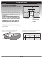
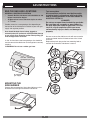
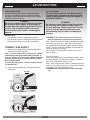
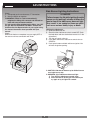
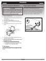
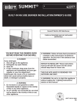
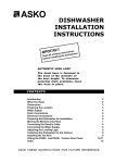
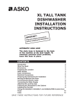
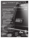
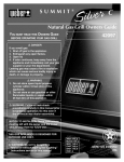
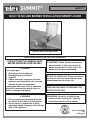
SUMMIT®
#
42377
BUILT-IN NG SIDE BURNER INSTALLATION/OWNER'S GUIDE
Summit® Built-In NG Side Burner
THESE ACCESSORIES MAY BE PURCHASED SEPARATELY.
YOU MUST READ THIS OWNERS GUIDE
BEFORE OPERATING YOUR GAS GRILL
DANGER
If you smell gas:
1. Shut off gas to the appliance.
2. Extinguish any open flames.
3. Open lid
4. If odor continues, keep away from the
appliance and immediately call your gas
supplier or your fire department.
Leaking gas may cause a fire or explosion
which can cause serious bodily injury or
death, or damage to property.
WARNING
1. Do not store spare liquid propane cylinder within 10 feet (3m) of this appliance.
2. Do not store or use gasoline or other
flammable liquids or vapors within 25 feet
(8m) of this appliance.
WARNING: Follow all leak-check procedures carefully in this manual prior to
barbecue operation. Do this even if the
barbecue was dealer-assembled.
NOTICE TO INSTALLER: These instructions
must be left with the owner and the owner
should keep them for future use.
THIS GAS APPLIANCE IS DESIGNED FOR
OUTDOOR USE ONLY.
WARNING: Do not try to light this appliance without reading the "Lighting"
Instructions section of this manual
42377 US 05/01/04
NG
US English
DANGERS & WARNINGS
DANGER
Failure to follow the Dangers, Warnings and Cautions contained in this Owner’s Manual may result in serious
bodily injury or death, or in a fire or an explosion causing damage to property.
WARNINGS
Do not store a spare or disconnected liquid propane cylinder under or near this barbecue.
Improper assembly may be dangerous. Please carefully follow the assembly instructions in this
manual.
After a period of storage, and/or nonuse, the Weber® Built-In side burner should be checked for gas
leaks and burner obstructions before use. See instructions in this manual for correct procedures.
Do not operate the Weber® Built-In side burner if there is a gas leak present.
Do not use a flame to check for gas leaks.
Combustible materials should never be within 24 inches of the top, bottom, back or sides of your
Weber® Built-In side burner.
Do not put a barbecue cover or anything flammable on, or in the storage area under the barbecue.
Built-In side burner barbecue should never be used by children. Accessible parts of the barbecue
may be very hot. Keep young children away while it is in use.
You should exercise reasonable care when operating your Weber® Built-In side burner. It will be hot
during cooking or cleaning and should never be left unattended, or moved while in operation.
Should the burner go out while in operation, turn the gas valve off. Open the lid and wait five
minutes before attempting to relight, using the lighting instructions.
Never lean over open side burner or place hands or fingers on the front edge of the side burner.
Should a grease fire occur, turn off burner and leave lid closed until fire is out.
Do not enlarge valve orifices or burner ports when cleaning the valve or burner.
The Weber® Built-In side burner should be thoroughly cleaned on a regular basis.
Liquid propane gas is not natural gas. The conversion or attempted use of natural gas in a liquid
propane unit or liquid propane gas in a natural gas unit is dangerous and will void your warranty.
Do not attempt to disconnect any gas fitting while your barbecue is in operation.
Use heat-resistant barbecue mitts or gloves when operating barbecue.
Keep any electrical supply cord and the fuel supply hose away from any heated surfaces.
Combustion byproducts produced when using this product contain chemicals known to the state of
California to cause cancer, birth defects, or other reproductive harm.
Do not use this Built-In side burner unless all parts are in place. The unit must be properly
assembled according to the instructions outlined in the “Assembly Instruction” section of the
Owner’s Guide.
LIQUID PROPANE GAS UNITS ONLY:
Use the regulator that is supplied with your Weber® gas barbecue.
Do not attempt to disconnect the gas regulator or any gas fitting while your barbecue is in
operation.
A dented or rusty liquid propane cylinder may be hazardous and should be checked by your liquid
propane supplier. Do not use a liquid propane cylinder with a damaged valve.
Although your liquid propane cylinder may appear to be empty, gas may still be present, and the
cylinder should be transported and stored accordingly.
If you see, smell or hear the hiss of escaping gas from the liquid propane cylinder:
1. Move away from liquid propane cylinder.
2. Do not attempt to correct the problem yourself.
3. Call your fire department.
2
WARRANTY
•
Warranty
Weber-Stephen Products Co. (Weber) hereby warrants to the ORIGINAL
PURCHASER of this Weber® gas grill that it will be free of defects in
material and workmanship from the date of purchase as follows:
Stainless Steel Lid,
All Remaining Parts,
•
•
10 years
5 years
when assembled and operated in accordance with the printed instructions
accompanying it.
Weber may require reasonable proof of your date of purchase. THEREFORE, YOU SHOULD RETAIN YOUR SALES SLIP OR INVOICE.
This Limited Warranty shall be limited to the repair or replacement of
parts that prove defective under normal use and service and which on
examination shall indicate, to Weber’s satisfaction, they are defective.
Before returning any parts, contact the Customer service representative
in your region using the contact information sheet provided with your
manual. If Weber® confirms the defect and approves the claim, Weber®
will elect to replace such parts without charge. If you are required to return defective parts, transportation charges must be prepaid. Weber® will
return parts to the purchaser, freight or postage prepaid.
This Limited Warranty does not cover any failures or operating difficulties due to accident, abuse, misuse, alteration, misapplication, vandalism, improper installation or improper maintenance or service, or failure
to perform normal and routine maintenance, including but not limited
to damage caused by insects within the burner tubes, as set out in this
owner’s manual.
Deterioration or damage due to severe weather conditions such as hail,
hurricanes, earthquakes or tornadoes, discoloration due to exposure
to chemicals either directly or in the atmosphere, is not covered by this
Limited Warranty.
This Weber® Built-In Side Burner is designed for natural (piped in city) gas only. Do not use liquid propane
(LP) bottled gas. The valves, orifices and hose are for
natural gas only.
Do not use with charcoal fuel.
Check that the area under the control panel and the
bottom tray are free from debris that might obstruct the
flow of combustion or ventilation air.
Storage
■ The gas must be turned OFF at the natural gas supply
when the Weber® Built-In Side Burner is not in use.
■ Check that the areas under the control panel and the
slide out bottom tray are free from debris that might
obstruct the flow of combustion or ventilation air.
Operating
WARNING: Only use this barbecue outdoors in
a well-ventilated area. Do not use in a garage,
building, breezeway or any other enclosed area.
WARNING: Your Weber® Built-In Side Burner shall
not be used under an unprotected combustible roof
or overhang.
WARNING: Your Weber® Built-In Side Burner is
not intended to be installed in or on recreational
vehicles and/or boats.
WARNING: Do not use the barbecue within 24
inches of combustible materials, top, bottom, back
or sides of the grill.
WARNING: The entire cooking box gets hot when in
use. Do not leave unattended.
WARNING: Keep any electrical supply cord and the
fuel supply hose away from any heated surface.
WARNING: Keep the cooking area clear of
flammable vapors and liquids, such as gasoline,
alcohol, etc., and combustible materials.
There are no other express warrants except as set forth herein and any
applicable implied warranties of merchantability and fitness are limited
in duration to the period of coverage of this express written Limited
Warranty. Some regions do not allow limitation on how long an implied
warranty lasts, so this limitation may not apply to you.
Weber® is not liable for any special, indirect or consequential damages.
Some regions do not allow the exclusion or limitation of incidental or consequential damages, so this limitation or exclusion may not apply to you.
Weber® does not authorize any person or company to assume for it any
other obligation or liability in connection with the sale, installation, use,
removal, return, or replacement of its equipment; and no such representations are binding on Weber®.
This Warranty applies only to products sold at retail.
Gas Supply Testing
WEBER-STEPHEN PRODUCTS CO.
Customer Service Center
1890 Roselle Road, Suite 308
Schaumburg, IL 60195
USA
•
www.weber.com
•
The natural gas supply is easy to use and gives you more
cooking control than charcoal fuel.
• These instructions will give you the minimum requirements for assembling your Weber® Built-In Side
Burner. Please read the instructions carefully before
using your Weber® Built-In Side Burner. Improper assembly can be dangerous.
• Not for use by children.
• If there are local codes that apply to portable gas grills,
you will have to conform to them. If there are no local
codes, you must conform to the latest edition of the
National Fuel Gas Code: ANSI Z 223.1/NFPA54.
3
Disconnect your Weber® gas barbecue when the gas
supply is being tested at high pressures. This appliance and its individual shutoff valve must be disconnected from the gas supply piping system during any
pressure testing of that system at test pressures in
excess of 1/2 psig (3.5 kPa).
Turn OFF your Weber® gas barbecue when the gas
supply is being tested at low pressures. This appliance
must be isolated from the gas supply piping system by
closing its individual manual shutoff valve during any
pressure testing of the gas supply piping system at the
pressure equal to or less than 1/2 psig (3.5 kPa).
GAS INSTRUCTIONS
LOCATING YOUR BUILT-IN SIDE BURNER
When determining a suitable location for your Built-In Side
Burner installation, give attention to concerns such as
exposure to wind, proximity to traffic paths, and keeping
any gas supply lines as short as possible. Never locate
the Summit® Built-In Side Burner in a garage, breezeway,
shed, under an unprotected overhang, or other enclosed
area. Locate the Side Burner and structure so there is
enough room to safely evacuate the area in case of a fire.
24 inches Any Surface
WARNING: The structure, “island” counter tops
and adjacent work areas for the LP Tank Cabinet
installation must be built from noncombustible
materials only.
Any Surface
24 inches min.
for lid clearance
24 inches
24 inches
Any Surface
CLEARANCE FROM COMBUSTIBLE SURFACES OR
STRUCTURES
WARNING: Clearance from the outside walls of
the sides and back of the LP Tank Cabinet must be a
minimum of 24 inches any surface. Refer to “Typical
Gas Supply Installation” before starting installation.
Side
Burner
Note: For a countertop
treatment: Recommended
3/4 inch overhang. Notch
front edge for frame to
fully slide in.
NOTE: If you have questions on what materials are considered noncombustible, contact you local building supplier
or fire department.
WARNING: All counter top finished surfaces must be
constructed of a noncombustible material.
BUILT-IN SRUCTURE CUTOUT DIMENSIONS
All dimensions are to finished surfaces.
A
B
C
4
Side Burner
Cut out Dimensions Tolerances
+ 1/4" - 1/4"
10 12"
3 3/4"
+ 1/4" - 1/4"
+ 1/4" - 1/4"
16 1/4"
GAS INSTRUCTIONS
Test connections
All connections and joints must be thoroughly
tested for leaks in accordance with local codes
and all listed procedures in the latest edition of
ANSI Z223.1/NFPA 54.
DANGER
Do not use an open flame to check for gas leaks.
Be sure there are no sparks or open flames in
the area while you check for gas leaks. This will
result in a fire or explosion which can cause
serious bodily injury or death, and damage to
property.
BUILT-IN GAS LINE LOCATIONS
GENERAL CONSTRUCTION DETAILS
• Summit® Built-In side burner unit should be on site
before construction begins.
• All dimensions have a tolerance of plus or minus
+/- 1/4” inch.
Provide access for a corrugated gas line depending on
the location of the side burner in relation to your main gas
supply and regulator position.
Area should be kept clear of sharp, jagged, or
extremely abrasive surfaces to avoid possible damage
to gas supply lines. Exercise caution when pulling gas
lines through built-in structure.
Be sure to secure the side burner unit with non corrosive
screws anchored into the finished surface of the “island
structure”.
Replace the plastic plug on the front mounting hole to
conceal the screw once side burner is secure.
A 3/8 “ inch stainless steel corrugated gas line should be
used to connect the side burner to the regulator accessory
coupling.
WARNING: Do not use a rubber gas hose.
3/8" SAE stainless
corregated gas line
to regulated
gas supply
MOUNTING THE
SIDE BURNER
Connect the corrugated gas line to the side burner valve
located on the back right hand side of side burner.
5
GAS INSTRUCTIONS
GAS LINE PIPING
TYPICAL NATURAL GAS SUPPLY
INSTALLATION
•
We recommend that this installation be done by a
LICENSED professional.
GENERAL SPECIFICATIONS FOR PIPING
•
•
Note - Contact your local municipality for building
codes regulating outdoor gas grill installations. In
absence of Local Codes, you must conform to the
latest edition of National Fuel Gas Code ANSI Z223.1/
NFPA54.
• This grill is designed to operate at 4.5 inches of water
column pressure.
• A manual shut-off valve must be installed outdoors,
and be accessible, not in the “built-in” structure. An
additional manual shut-off valve indoors should be installed in the branch fuel line in an accessible location
near the supply line.
Caution: If young children are in the area, a locking
valve should be considered.
• Pipe compound should be used which is resistant to
the action of liquid propane gas when gas connections
are made.
• The gas connections must be firmly attached to rigid,
permanent construction.
•
•
•
•
•
•
Refer to the piping chart at the bottom of previous
page.
The corrugated gas line from the manifold is 58 inches
long. Do not extend the gas line.
We have provided the means to make an SAE 45°
flare connection. Do not use pipe sealant on this
connection.
If the length of line required does not exceed 50 feet,
use a 5/8” O.D. tube. One size larger should be used
for lengths greater than 50 feet. Refer to piping chart.
Gas piping may be copper tubing, type K or L;
polyethylene plastic tube, with a minimum wall
thickness of .062 inch; or standard weight (schedule
40) steel or wrought iron pipe.
Copper tubing must be tin-lined if the gas contains
more than 0.3 grams of hydrogen sulfide per 100 cubic
feet of gas.
Plastic tubing is suitable only for outdoor, underground
use.
Gas piping in contact with earth, or any other material
which may corrode the piping, must be protected
against corrosion in an approved manner.
Underground piping must have a minimum of 18”
cover.
Note: The information provided in this manual is
general for typical installations. We cannot cover all
possible installation ideas. We recommend, prior to
installation, that you contact your municipality for
local building codes and your local fire department for
installation verification.
If you have any questions, contact Customer Service
at 1-800-446-1071
Table
10-1
Maximum Capacity of Pipe in Cubic Feet of Gas per Hour for Gas Pressures of 0.5 psi or Less and a Pressure Drop of 0.3 Inch
Water Column. (Based on a 0.60 Specific Gravity Gas)
Nominal
Iron Pipe
Size
(Inches)
Internal
Diameter
(Inches)
Length of Pipe (Feet)
10
20
30
40
50
60
70
80
90
1/4
.364
32
22
18
15
14
12
11
11
10
9
8
8
7
6
3/8
.493
72
49
40
34
30
27
25
23
22
21
18
17
15
14
1/2
.622
132
92
73
63
56
50
46
43
40
38
34
31
28
26
100
125
150
175
200
3/4
.824
278
190
152
130
115
105
96
90
84
79
72
64
59
55
1
1.049
520
350
285
245
215
195
180
170
160
150
130
120
110
100
1 1/4
1.380
1050
730
590
500
440
400
370
350
320
305
275
250
225
210
1 1/2
1.160
1600
1100
890
760
670
610
560
530
490
460
410
380
350
320
2
2.067
3050
2100
1650
1450
1270
1150
1050
990
930
870
780
710
650
610
2 1/2
2.469
4800
3300
2700
2300
2000
1850
1700
1600
1500
1400
1250
1130
1050
980
3
3.068
8500
5900
4700
4100
3600
3250
3000
2800
2600
2500
2200
2000
1850
1700
4
4.026
17500
12000
9700
8300
7400
6800
6200
5800
5400
5100
4500
4100
3800
3500
©1997 National Fire Protection Association, Inc., and International Approval Services - U.S., Inc. All Rights Reserved.
6
GAS INSTRUCTIONS
TEST CONNECTIONS
Test connections
All connections and joints must be thoroughly
tested for leaks in accordance with local codes
and all listed procedures in the latest edition of
ANSI Z223.1/NFPA 54.
All connections and joints must be thoroughly tested
for leaks in accordance with local codes and all listed
procedures in the latest edition of the National Fuel Gas
Code ANSI Z223.1/NFPA 54.
DANGER
DANGER
Do not use an open flame to check for gas leaks.
Be sure there are no sparks or open flames in
the area while you check for gas leaks. This will
result in a fire or explosion which can cause
serious bodily injury or death, and damage to
property.
Do not use an open flame to check for gas leaks.
Be sure there are no sparks or open flames in
the area while you check for gas leaks. This will
result in a fire or explosion which can cause
serious bodily injury or death, and damage to
property.
REGULATOR
•
•
•
WARNING: You should check for gas leaks every
time you disconnect and reconnect a gas fitting.
Note - All factory-made connections have been thoroughly
checked for gas leaks. As a safety precaution however,
you should recheck all fittings for leaks before using your
Summit® Built-In side burner. Shipping and handling may
loosen or damage a gas fitting.
You will need: a soap and water solution, and a rag or
brush to apply it.
The regulator should be adequately supported.
The regulator must be installed close to the appliance.
Each appliance must have a separate regulator.
CONNECT GAS SUPPLY
1) Uncap the flare fitting from the optional side burner
connection located at regulator.
Note: You must connect your side burner to a Weber®
approved regulator(part number #62434) located at
main gas supply. If you do not use a Weber® approved
regulator the Warranty on the Summit® Built-In Side
Burner will be voided.
If you have any questions, contact Customer Service
at 1-800-446-1071
Turn on gas supply.
Check for leaks by wetting the connections with the soap
and water solution and watching for bubbles. If bubbles
form or if a bubble grows, there is a leak.
Note - Since some leak test solutions, including soap and
water, may be slightly corrosive, all connections should be
rinsed with water after checking for leaks.
WARNING: Do not ignite burners when leak checking.
2) Connect the corrugated gas line to the side burner
Connection.
top view
Cap
(Optional
Side Burner)
Hard piped
gas supply
Figure 1
Regulator
top view
Hard piped
gas supply
to side burner
Regulator
Figure 2
7
GAS INSTRUCTIONS
Side Burner Lighting Instructions
Check:
1) Corrugated gas line-to-Accessory “T” Connection.
2) Main gas Supply to regulator
WARNING: If there is a leak a connection(1),
retighten the fitting with a wrench and recheck for
leaks with soap and water solution.
If a leak persists after retightening the fitting, turn OFF
the gas. DO NOT OPERATE THE GRILL. Contact the
Customer Service Representative in your region using
the contact information sheet provided with your
manual.
Check:
When leak checks are complete, turn gas supply OFF at
the source and rinse connections with water.
DANGER
Failure to open the lid while igniting the side
burner, or not waiting 5 minutes to allow the
gas to clear if the side burner does not light,
may result in an explosive flame-up which
can cause serious bodily injury or death.
Lighting the side burner.
1) Open the side burner lid.
2) Check that the side burner valve is turned OFF. (Push
the knob down and turn clockwise to ensure it is in the
off position.).
3) Turn the gas supply valve on.
4) Push down and turn the side burner control valve to
START/HI.
5) Push igniter button and hold until burner ignites. You
will hear the igniter sparking.
TOPVIEW
TOSIDE
BURNER
TOREGULATOR
CAUTION: Side burner flame may be difficult to see
on a bright sunny day.
WARNING: If the side burner does not light:
1) Turn OFF the side burner control valve.
2) Wait 5 minutes to let the gas clear before you
try again or try to light with a match.
8
OPERATING
Manually Lighting the Side Burner
Replace Igniter Batteries
DANGER
Failure to open the lid while igniting the side
burner, or not waiting 5 minutes to allow the
gas to clear if the side burner does not light,
may result in an explosive flame-up which can
cause serious bodily injury or death.
Parts required: 1 AA alkaline battery per igniter.
Unscrew igniter button from top of control panel. Remove
igniter button and contact spring. Remove old battery and
replace with a new AA alkaline battery. Positive end(1) of
battery faces up as shown in illustration. Replace spring
contact(2) and screw igniter button(3) back down.
1) Open the side burner lid.
2) Check that the side burner valve is turned OFF. (Push
the knob down and turn clockwise to ensure that it is in
the off position.).
3) Turn the gas supply valve on.
4) Put match in a match holder and strike match.
5) Push down and turn the side burner control valve to
START/HI.
6) Hold match holder and lit match by right side of side
burner.
7) Push igniter button and hold until burner ignites. You
will hear the igniter sparking.
CAUTION: Side burner flame may be difficult to see
on a bright sunny day.
WARNING: If the side burner does not light:
1) Turn OFF the side burner control valve.
2) Wait 5 minutes to let the gas clear before you
try again or try to light with a match.
To Extinguish
Push down and turn each burner control knob clockwise to the OFF position. Turn gas supply OFF at the
source.
9
SIDE BURNER TROUBLESHOOTING
Problem
Check
Cure
Side Burner does not light.
Is gas supply off?
Turn supply on.
Flame is low in HIGH position.
Is the fuel hose bent or kinked?
Straighten gas line.
Push button ignition does not
work.
Does burner light with a match?
If match lights burner, check
igniter (see below).
If problems cannot be corrected by using these methods, please contact the Customer
Service Representative in your region using the contact information sheet provided
with your manual.
Side Burner maintenance
1) Igniter Wire
2) Burner
3) 1/8 to 3/16 inch gap between electrode and burner
WARNING: All gas controls and supply valves
should be in the OFF position.
(3)
Make sure wire is connected between the igniter and
electrode. Adjust igniter electrode to burner. Gap should
be 1/8 to 3/16 inch from tip of electrode to burner. Spark
should be a white/blue color, not yellow.
Side Burner Grate
Side Burner Cap
Side Burner Ring & Head
Igniter Electrode
Control Knob
Igniter
10