1
Instruction
No.
GF-117
AERCO INTERNATIONAL, Inc., Northvale, New Jersey, 07647 USA
Installation, Operation
& Maintenance Instructions
Benchmark 3.0
Dual-Fuel Series
Gas Fired
Low NOx
Boiler System
Natural Gas and Propane Fired,
Condensing, Forced Draft Hot Water Boiler
3,000,000 BTU/H Input
Applicable to Serial Numbers G-09-0298 and above
Printed in U.S.A.
REVISED APRIL, 2009
Telephone Support
Direct to AERCO Technical Support
(8 to 5 pm EST, Monday through Friday):
1-800-526-0288
The information contained in this
installation, operation and maintenance manual is subject to
change without notice from
AERCO International, Inc.
AERCO International, Inc.
159 Paris Avenue
Northvale, NJ 07647-0128
www.aerco,com
© AERCO International, Inc., 2009
AERCO makes no warranty of any
kind with respect to this material,
including but not limited to implied
warranties of merchantability and
fitness for a particular application.
AERCO International is not liable
for errors appearing in this
manual. Nor for incidental or
consequential damages occurring
in connection with the furnishing,
performance, or use of this
material.
CONTENTS
GF-117 - AERCO BENCHMARK 3.0 DUAL-FUEL LOW NOx BOILER
Operating & Maintenance Instructions
FOREWORD
A
Chapter 1 – SAFETY PRECAUTIONS
Para.
1-1
1-2
Subject
Warnings & Cautions
Emergency Shutdown
Page
1-1
1-2
1-1
Para.
1-3
Subject
Prolonged Shutdown
Chapter 2 – INSTALLATION
Para.
2.1
2.2
2.3
2.4
2.5
2.6
2.7
2.8
Subject
Introduction
Receiving the Unit
Unpacking
Site Preparation
Supply and Return Piping
Condensate Drains
Gas Supply Piping
AC Electrical Power Wiring
2-1
Page
2-1
2-1
2-1
2-1
2-3
2-3
2-5
2-6
Para.
2.9
2.10
2.11
2.12
2.13
Subject
Modes of Operation and Field
Control Wiring
I/O Box Connections
Auxiliary Relay Contacts
Flue Gas Vent Installation
Combustion Air
Chapter 3 – CONTROL PANEL COMPONENTS AND
OPERATING PROCEDURES
Para.
3.1
3.2
3.3
3.4
3.5
Subject
Introduction
Control Panel Description
Control Panel Menus
Operating Menu
Setup Menu
Page
3-1
3-1
3-4
3-5
3-5
Para.
3.6
3.7
3.8
3.9
Subject
Configuration Menu
Tuning Menu
Start Sequence
Start/Stop Levels
Chapter 4 – INITIAL START-UP
Para.
4.1
4.2
4.3
Subject
Initial Startup Requirements
Tools and Instruments for
Combustion Calibration
Natural Gas Combustion
Calibration
Page
1-2
Page
2-7
2-8
2-10
2-10
2-10
3-1
Page
3-6
3-7
3-7
3-9
4-1
Page
4-1
4-1
Para.
4.4
4.5
Subject
Unit Reassembly
Over-Temperature Limit Switch
Page
4-5
4-5
4-2
i
CONTENTS
Chapter 5 – MODE OF OPERATION
Para.
5.1
5.2
5.3
5.4
5.5
Subject
Introduction
Indoor/Outdoor Reset Mode
Constant Setpoint Mode
Remote Setpoint Mode
Direct Drive Modes
5-1
Page
5-1
5-1
5-2
5-2
5-3
Para.
5.6
5.7
Subject
Boiler Management System
(BMS)
Combination Control System
(CCS)
Page
5-4
5-5
Chapter 6 – SAFETY DEVICE TESTING PROCEDURES
6-1
Para.
6.1
6.2
Page
6-4
6-5
6.3
6.4
6.5
6.6
6.7
Subject
Testing of Safety Devices
Natural Gas Low Gas Pressure
Switch Test
Propane Low Gas Pressure
Switch Test
Natural Gas High Gas Pressure
Switch Test
Propane High Gas Pressure
Switch Test
Low Water Level Fault Test
Water Temperature Fault Test
Page
6-1
6-1
Para.
6.8
6.9
Subject
Interlock Tests
Flame Fault Test
6-2
6.10
6.11
6.12
6-2
6.13
6-3
6-3
6.14
Air Flow Fault Test
SSOV Proof of Closure Switch
Purge Switch Open During
Purge
Ignition Switch Open During
Ignition
Safety Pressure Relief Valve
Test
6-2
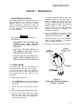
Chapter 7 – MAINTENANCE REQUIREMENTS
Para.
7.1
7.2
7.3
7.4
7.5
7.6
Subject
Maintenance Schedule
Spark Ignitor
Flame Detector
Combustion Calibration
Safety Device Testing
Burner
Page
7-1
7-1
7-2
7-2
7-3
7-3
Para.
7.7
7.8
7.9
ii
Subject
Introduction
Page
8-1
6-6
6-7
7-1
Subject
Condensate Drain Trap
Shutting the Boiler Down For An
Extended Period of Time
Placing The Boiler Back In
Service After A Prolonged
Shutdown
Chapter 8 – TROUBLESHOOTING GUIDE
Para.
8.1
6-5
6-5
6-6
Page
7-4
7-5
7-5
8-1
Para.
Subject
Page
CONTENTS
APPENDICES
App
A
B
C
D
E
Subject
Boiler Menu Item Descriptions
Startup, Status and Fault
Messages
Temperature Sensor Resistance
Chart
Indoor/Outdoor Reset Ratio
Charts
Boiler Default Settings
WARRANTIES
Page
A-1
B-1
C-1
D-1
E-1
App
F
G
H
I
J
K
Subject
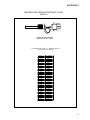
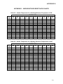
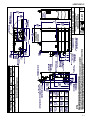
Dimensional and Part Drawings
Piping Drawings
Wiring Schematics
Recommended Periodic Testing
Checklist
Benchmark Control Panel Views
Benchmark 3.0 Dual-Fuel
Switchover Instructions
Page
F-1
G-1
H-1
I-1
J-1
K-1
W-1
iii
FOREWORD
Foreword
The AERCO Benchmark 3.0 Dual-Fuel Boiler is a modulating unit. It represents a true industry
advance that meets the needs of today's energy and environmental concerns. Designed for
application in any closed loop hydronic system, the Benchmark's modulating capability relates
energy input directly to fluctuating system loads. The Benchmark 3.0, with its 15:1 turn down
ratio and condensing capability, provides extremely high efficiencies and makes it ideally suited
for modern low temperature, as well as, conventional heating systems.
The Benchmark 3.0 operates at inputs ranging from 200,000 BTU/hr. to 3,000,000 BTU/hr. The
output of the boiler is a function of the unit’s firing rate and return water temperature. Output
ranges from 198,000 BTU/hr. to 2,900,000 BTU/hr., depending on operating conditions.
When installed and operated on natural gas in accordance with this Instruction Manual, the
Benchmark 3.0 Boiler complies with the NOx emission standards outlined in:
• South Coast Air Quality Management District (SCAQMD), Rule 1146.1
Whether used in singular or modular arrangements, the Benchmark 3.0 offers the maximum
flexibility in venting with minimum installation space requirements. The Benchmark's advanced
electronics are available in several selectable modes of operation offering the most efficient
operating methods and energy management system integration.
For service or parts, contact your local sales representative or AERCO INTERNATIONAL.
NAME:
ORGANIZATION:
ADDRESS:
TELEPHONE:
INSTALLATION DATE: _____________________________________________
A
SAFETY PRECAUTIONS
CHAPTER 1
SAFETY PRECAUTIONS
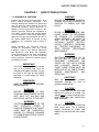
1.1 WARNINGS & CAUTIONS
Installers and operating personnel MUST, at all
times, observe all safety regulations.
The
following warnings and cautions are general and
must be given the same attention as specific
precautions included in these instructions. In
addition to all the requirements included in this
AERCO Instruction Manual, the installation of
units MUST conform with local building codes,
or, in the absence of local codes, ANSI Z223.1
(National Fuel Gas Code Publication No. NFPA54). Where ASME CSD-1 is required by local
jurisdiction, the installation must conform to
CSD-1.
Where applicable, the equipment shall be
installed in accordance with the current
Installation Code for Gas Burning Appliances
and Equipment, CGA B149, and applicable
Provincial regulations for the class; which should
be carefully followed in all cases. Authorities
having jurisdiction should be consulted before
installations are made.
IMPORTANT
This Instruction Manual is an integral
part of the product and must be
maintained in legible condition. It must
be given to the user by the installer
and kept in a safe place for future
reference.
WARNINGS!
MUST BE OBSERVED TO PREVENT
SERIOUS INJURY.
WARNING!
WARNING
DO NOT USE MATCHES, CANDLES,
FLAMES, OR OTHER SOURCES OF
IGNITION TO CHECK FOR GAS
LEAKS.
WARNING!
FLUIDS UNDER PRESSURE MAY
CAUSE INJURY TO PERSONNEL
OR DAMAGE TO EQUIPMENT
WHEN RELEASED. BE SURE TO
SHUT OFF ALL INCOMING AND
OUTGOING
WATER
SHUTOFF
VALVES. CAREFULLY DECREASE
ALL TRAPPED PRESSURES TO
ZERO
BEFORE
PERFORMING
MAINTENANCE.
WARNING!
ELECTRICAL VOLTAGES UP TO
460 VAC MAY BE USED IN THIS
EQUIPMENT. THEREFORE THE
COVER ON THE UNIT’S POWER
BOX (LOCATED BEHIND THE
FRONT PANEL DOOR) MUST BE
INSTALLED AT ALL TIMES, EXCEPT
DURING
MAINTENANCE
AND
SERVICING.
CAUTIONS!
Must be observed to prevent
equipment damage or loss of
operating effectiveness.
CAUTION!
BEFORE ATTEMPTING TO PERFORM ANY MAINTENANCE ON THE
UNIT, SHUT OFF ALL GAS AND
ELECTRICAL INPUTS TO THE UNIT.
Many soaps used for gas pipe leak
testing are corrosive to metals. The
piping must be rinsed thoroughly with
clean water after leak checks have
been completed.
WARNING!
CAUTION!
THE EXHAUST VENT PIPE OF THE
UNIT
OPERATES
UNDER
A
POSITIVE PRESSURE AND THEREFORE MUST BE COMPLETELY
SEALED TO PREVENT LEAKAGE
OF COMBUSTION PRODUCTS INTO
LIVING SPACES.
DO NOT use this boiler if any part has
been under water. Call a qualified
service technician to inspect and
replace any part that has been under
water.
1-1
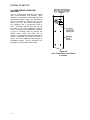
SAFETY PRECAUTIONS
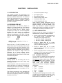
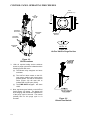
1.2 EMERGENCY SHUTDOWN
1.3 PROLONGED SHUTDOWN
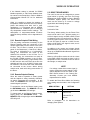
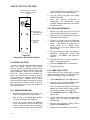
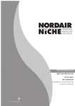
If overheating occurs or the gas supply fails to
shut off, close the manual gas shutoff valve
(Figure 1-1) located external to the unit.
After prolonged shutdown, it is recommended
that the startup procedures in Chapter 4 and the
safety device test procedures in Chapter 6 of
this manual be performed, to verify all systemoperating parameters. If there is an emergency,
turn off the electrical power supply to the
AERCO boiler and close the manual gas valve
located upstream the unit. The installer is to
identify the emergency shut-off device.
IMPORTANT
The Installer must identify and indicate
the location of the emergency shutdown
manual gas valve to operating personnel.
Figure 1-1
Manual Gas Shutoff Valve
1-2
INSTALLATION
CHAPTER 2
INSTALLATION
2.1 INTRODUCTION
• Pressure/Temperature Gauge
This Chapter provides the descriptions and
procedures necessary to unpack, inspect and
install the AERCO Benchmark 3.0 Dual-Fuel
Boiler. Brief descriptions are also provided for
each available mode of operation. Detailed
procedures for implementing these modes are
provided in Chapter 5.
• Spare Spark Igniter
2.2 RECEIVING THE UNIT
Each Benchmark 3.0 Dual-Fuel System is
shipped as a single crated unit. The shipping
weight is approximately 2,170 pounds. The unit
must be moved with the proper rigging
equipment for safety and to avoid equipment
damage. The unit should be completely
inspected for evidence of shipping damage and
shipment completeness at the time of receipt
from the carrier and before the bill of lading is
signed.
NOTE
AERCO is not responsible for lost or
damaged freight.
Each unit has a Tip-N-Tell indicator on the
outside of the crate. This indicates if the unit has
been turned on its side during shipment. If the
Tip-N-Tell indicator is tripped, do not sign for the
shipment. Note the information on the carrier’s
paperwork and request a freight claim and
inspection by a claims adjuster before
proceeding. Any other visual damage to the
packaging materials should also be made clear
to the delivering carrier.
2.3 UNPACKING
Carefully unpack the unit taking care not to
damage the unit enclosure when cutting away
packaging materials
A close inspection of the unit should be made to
ensure that there is no evidence of damage not
indicated by the Tip-N-Tell indicator. The freight
carrier should be notified immediately if any
damage is detected.
The following accessories come standard with
each unit and are either packed separately
within the unit’s packing container or are factory
installed on the boiler:
• Spare Flame Detector
• ASME Pressure Relief Valve
• Condensate Drain Trap
• 2” Gas Supply Shutoff Valve
When ordered, optional accessories may be
packed separately, packed within the boiler
shipping container, or may be installed on the
boiler. Any standard or optional accessories
shipped loose should be identified and stored in
a safe place until ready for installation or use.
2.4 SITE PREPARATION
Ensure that the site selected for installation of
the Benchmark 3.0 Dual Fuel Boiler includes:
• Access to AC Input Power corresponding to
the ordered power configuration. The
available power configurations are:
•
•
208 VAC, 3-Phase, 60 Hz @ 20 A
460 VAC, 3-Phase, 60 Hz @ 15 A
• Access to Natural Gas line at a static
pressure between 5.7” W.C.(min) and 2 psi
(max) for Standard (FM) option
• Access to Natural Gas line at a static
pressure between 6.5” W.C. (min.) and 2 psi
(max.) for IRI option
• Access to Propane Gas at a static pressure
between 3.5” W.C. (min.) and 2 psi (max.) for
both Standard (FM) and IRI options
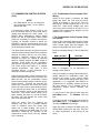
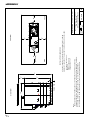
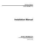
2.4.1 Installation Clearances
The unit must be installed with the prescribed
clearances for service as shown in Figure 2-1.
The minimum clearance dimensions, required by
AERCO, are listed below. However, if Local
Building Codes require additional clearances,
these codes shall supersede AERCO’s
requirements. Minimum acceptable clearances
required are:
• Sides:
24 inches
• Front :
24 inches
• Rear:
43 inches
• Top:
18 inches
All gas piping, water piping and electrical conduit
or cable must be arranged so that they do not
interfere with the removal of any panels, or
inhibit service or maintenance of the unit.
2-1
INSTALLATION
Figure 2-1 Benchmark 3.0 Dual Fuel Boiler Clearances
WARNING
KEEP THE UNIT AREA CLEAR AND
FREE FROM ALL COMBUSTIBLE
MATERIALS
AND
FLAMMABLE
VAPORS OR LIQUIDS.
CAUTION
While packaged in the shipping
container, the boiler must be moved
by pallet jack or forklift from the
FRONT ONLY.
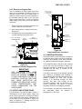
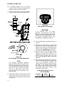
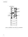
2.4.2 Setting the Unit
The unit must be installed on a 4 inch to 6 inch
housekeeping pad to ensure proper condensate
drainage. If anchoring the unit, refer to the
dimensional drawings in Appendix F for anchor
locations. A total of 3 lifting tabs are provided at
the top of the primary heat exchanger as shown
in Figure 2-2. However, USE ONLY TABS 1
AND 2 SHOWN IN FIGURE 2-2 TO MOVE THE
ENTIRE UNIT. Tabs 1 and 3 are used only
when removing or replacing the unit’s primary
heat exchanger. Remove the front top panel
from the unit to provide access to the lifting tabs.
Remove the four (4) lag screws securing the unit
to the shipping skid. Lift the unit off the shipping
skid and position it on the 4 inch to 6 inch
housekeeping concrete pad (required) in the
desired location.
2-2
Figure 2-2
Lifting Lug Locations
In multiple unit installations, it is important to
plan the position of each unit in advance.
Sufficient space for piping connections and
future service/maintenance requirements must
also be taken into consideration. All piping must
include ample provisions for expansion.
If installing a Combination Control Panel (CCP)
system, it is important to identify the
Combination Mode Boilers in advance and place
them in the proper physical location. Refer to
Chapter 5 for information on Combination Mode
Boilers.
INSTALLATION
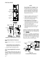
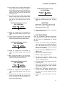
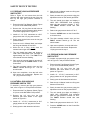
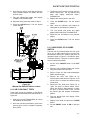
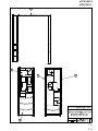
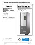
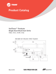
2.4.3 Removal of Support Rod
Prior to installation of water supply and return
piping, the 24” threaded rod shown in Figure 2-3
must be removed. This rod is installed prior to
shipment from the factory to prevent damage to
the insulated metal flex hose on the hot water
supply outlet of the boiler. In order to install the
water supply piping, this rod must be removed
as follows:
1. Refer to Figure 2-3 and back off the hex nut
on the outlet side of the flex hose.
BOILER SUPPLY
4" – 150# FLANGED
CONNECTION
BOILER RETURN
4" – 150# FLANGED
CONNECTION
EXHAUST
MANIFOLD
2. Next, disconnect the coupling nut from the
flange stud.
3. Completely remove the threaded rod, hex
nut and coupling nut from the boiler.
5/8-11 x 24" LONG
THREADED ROD
5/8-11
HEX NUT
SHELL
DRAIN
VALVE
2" NATURAL
GAS INLET
CONNECTION
5/8-11
COUPLING NUT
OUTLET
FLANGE
2" PROPANE
INLET
CONNECTION
REAR VIEW
(SEE IMPORTANT
NOTE BELOW)
EXHAUST
MANIFOLD
PARTIAL TOP VIEW - REAR
Figure 2-3
Location of Threaded Support Rod
IMPORTANT
THE INSULATED FLEX HOSE
SHOWN IN FIGURE 2-3 MUST BE
LEVEL OR SLOPING UPWARD AS
IT EXITS THE BOILER. FAILURE TO
PROPERLY POSITION THIS HOSE
MAY CAUSE INEFFECTIVE AIR
ELIMINATION RESULTING IN ELEVATED TEMPERATURES THAT
COULD COMPROMISE THE TOP
HEAD GASKET.
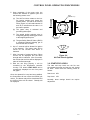
2.5 SUPPLY AND RETURN PIPING
The Benchmark 3.0 Dual-Fuel Boiler utilizes 4”
150# flanges for the water system supply and
return piping connections. The physical location
of the supply and return piping connections are
on the rear of the unit as shown in Figure 2-4.
Refer to Appendix F, Drawing AP-A-811 for
additional dimensional data.
Figure 2-4
Supply and Return Locations
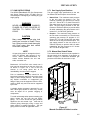
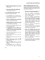
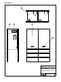
2.6 CONDENSATE DRAINS
The Benchmark 3.0 Dual-Fuel Boiler is designed
to condense water vapor from the flue products.
Therefore, the installation must have provisions
for suitable condensate drainage or collection.
Two condensate drain connections are provided
on the rear of the unit as shown in Figure 2-5.
One drain connection is located on the exhaust
manifold and the other is located on the
connecting manifold.
The drain at the bottom of the exhaust manifold
also includes a condensate trap containing a
float assembly. When condensate collects in the
exhaust manifold, the float rises, thereby
allowing it to discharge through the drain
opening. The drain pipe located on the
connecting manifold must be connected to a
second condensate trap which is packed
separately within the unit’s shipping container.
The procedures to install and connect both of
the condensate drains are provided in
paragraphs 2.6.1 and 2.6.2.
2-3
INSTALLATION
NOTE
A
EXHAUST
MANIFOLD
CONDENSATE
TRAP
A
The condensate trap described in the
following steps can be installed on the
floor behind the unit as shown in Figure 26. There will be sufficient downward slope
from the drain pipe to the trap inlet to
drain the condensate by gravity. Ensure
that the outlet hose from the trap slopes
away (down) from the trap.
DRAIN
SHELL DRAIN
VALVE
B
CONNECTING
MANIFOLD
2. Install 3/4” NPT nipples in the tapped inlet
and outlet of the condensate trap.
DRAIN
B
REAR VIEW
EXHAUST
MANIFOL
D
UNIT
FRAME
CONDENSATE
TRAP
DRAIN
1. Position the supplied condensate trap (part no.
24060) on the floor at the rear of the unit.
UNIT
FRAME
SHEL
L
3. Attach a length of 1½” I.D. hose (part no.
GM-123352) between the connecting
manifold drain pipe and the inlet side of the
condensate trap (Figure 2-6). Secure both
ends of the hose with clamps.
4. Connect a second length of 1” I.D.
polypropylene hose to the outlet side of the
condensate trap and route it to a nearby
floor drain.
DRAIN
VALVE
HOSE
CLAMP
1" I.D.
HOSE
TO FLOOR
DRAIN
VIEW “A - A”
CONNECTIN
G
MANIFOLD
TO
CONDENSATE
TRAP
CONDENSAT
E
DRAIN PIPE
VIEW “B - B”
Figure 2-5
Condensate Drain Connection Location
If desired, a Tee fitting may be used to connect
the two drain hoses from the exhaust manifold
and the outlet side of the of the condensate trap
connected in
If a floor drain is not available, a condensate pump
can be used to remove the condensate to drain.
The maximum condensate flow rate is 20 GPH.
The condensate drain trap, associated fittings and
drain lines must be removable for routine
maintenance; therefore, DO NOT hard pipe.
2.6.1 Exhaust Manifold Condensate
Drain
Refer to Figure 2-5, View A – A and install as
follows:
1. Connect a length of 1 inch I.D. hose (part no.
91030) to the drain on the connecting manifold
and secure it in place with a hose clamp.
2. Route the hose to a nearby floor drain.
2.6.2 Connecting Manifold Condensate
Drain
The connecting manifold drain pipe shown in
Figure 2-5, View B – B must be connected to a
separate condensate drain trap external to the
unit. Refer to Figure 2-6 and install the trap as
follows:
2-4
Figure 2-6
Condensate Trap Installation
INSTALLATION
2.7 GAS SUPPLY PIPING
The AERCO Benchmark 3.0 Gas Components
and Supply Design Guide, GF-3030 must be
consulted prior to designing or installing any gas
supply piping.
WARNING
NEVER USE MATCHES, CANDLES,
FLAMES OR OTHER SOURCES OF
IGNITION TO CHECK FOR GAS
LEAKS.
CAUTION
Many soaps used for gas pipe leak
testing are corrosive to metals. Therefore, piping must be rinsed thoroughly
with clean water after leak checks
have been completed.
NOTE
All gas piping must be arranged so that it
does not interfere with removal of any
covers, inhibit service/maintenance, or
restrict access between the unit and
walls, or another unit.
2.7.1 Gas Supply Specifications
The gas supply input specifications to the unit
for Natural Gas and Propane are as follows:
• Natural Gas - The maximum static pressure
to the unit must not exceed 2 psi. The
minimum operating gas pressure for natural
gas is 5.7 inches W.C. for both FM and IRI
gas trains when the unit is firing at maximum
input. The gas supply pressure to the unit
must be of sufficient capacity to provide 3000
cfh while maintaining the gas pressure at 6.5
inches W.C. for FM or IRI gas trains.
• Propane - The maximum static pressure to
the unit must not exceed 2 psi. The minimum
operating gas pressure for propane is 3.5
inches W.C. for both FM and IRI gas trains
when the unit is firing at maximum input. The
gas supply pressure to the unit must be of
sufficient capacity to provide 1200 cfh while
maintaining the gas pressure at 3.5 inches
W.C. for FM or IRI gas trains.
2.7.2 Manual Gas Shutoff Valve
Two manual shut-off valves must be installed in
the gas supply lines upstream of the Boiler as
shown in Figure 2-7. Maximum allowable gas
pressure to the Boiler for each line is 2 psi
Benchmark 3.0 Dual-Fuel units contain two 2
inch gas inlet connections on the rear of the unit
as shown in Figure 2-4. If one of the fuel
sources is not being piped due to its
unavailability, the inlet must be capped.
Prior to installation, all pipes should be deburred and internally cleared of any scale, metal
chips or other foreign particles. Do Not install
any flexible connectors or unapproved gas
fittings. Piping must be supported from the floor,
ceiling or walls only and must not be supported
by the unit.
A suitable piping compound, approved for use
with natural gas, should be used. Any excess
must be wiped off to prevent clogging of
components.
To avoid unit damage when pressure testing gas
piping, isolate the unit from the gas supply
piping. At no time should the gas pressure
applied to the unit exceed 2 psi. Leak test all
external piping thoroughly using a soap and
water solution or suitable equivalent. The gas
piping used must meet all applicable codes.
Figure 2-7
Manual Gas Shut-Off Valve Location
2-5
INSTALLATION
2.7.3 IRI Gas Train Kit
2.8.1 Electrical Power Requirements
The IRI gas train is an optional gas train
configuration which is required in some areas for
code compliance or for insurance purposes.
The IRI gas train is factory pre-piped and wired.
See Appendix F, Drawing AP-A-803 for details.
The AERCO Benchmark 3.0 Dual-Fuel Boiler is
available
in
two
different
AC
power
configurations:
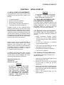
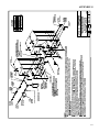
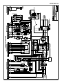
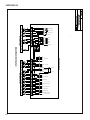
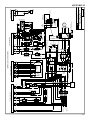
2.8 AC ELECTRICAL POWER WIRING
The AERCO Benchmark 3.0 Electrical Power
Wiring Guide, GF-3060, must be consulted prior
to connecting any AC power wiring to the unit.
External AC power connections are made to the
unit inside the Power Box on the front panel of
the unit. Remove the front door of the unit to
access the Power Box mounted directly above
the Control Box. Loosen the four Power Box
cover screws and remove cover to access the
AC terminal connections inside the Power Box
(Figure 2-8).
NOTE
All electrical conduit and hardware must
be installed so that it does not interfere
with the removal of any unit covers, inhibit
service/maintenance, or prevent access
between the unit and walls or another
unit.
• 208 VAC/3-Phase/60 @20 amps
• 460 VAC/3-Phase/60 Hz @ 15 amps
Each of the power configurations utilize a Power
Box with a terminal block that matches the
configuration ordered. The two different terminal
block configurations are shown in Figure 2-9. A
wiring diagram showing the required AC power
connections is provided on the front cover of the
Power Box.
Each Benchmark 3.0 Dual-Fuel Boiler must be
connected to a dedicated electrical circuit. NO
OTHER DEVICES SHOULD BE ON THE SAME
ELECTRICAL CIRCUIT AS THE BENCHMARK
UNIT. A means for disconnecting AC power
from the unit (such as a service switch) must be
installed near the unit for normal operation and
maintenance. All electrical connections should
be made in accordance with the National
Electrical Code and/or with any applicable local
codes.
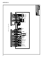
For electrical power wiring diagrams, see the
AERCO Benchmark 3.0 Electrical Power Wiring
Guide, (GF-3060).
Figure 2-9
AC Terminal Block Configurations
Figure 2-8
AC Input Terminal Block Location
2-6
INSTALLATION
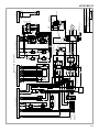
2.9 MODES OF OPERATION AND FIELD
CONTROL WIRING
The Benchmark 3.0 Dual-Fuel Boiler is available
in several different modes of operation. While
each unit is factory configured and wired for its
intended mode, some additional field wiring may
be required to complete the installation. This
wiring is typically connected to the Input/Output
(I/O) Box located on the lower portion of the unit
front panel (Figure 2-10) behind the removable
front door.
To access the I/O Box terminal strips shown in
Figure 2-10, loosen the four cover screws and
remove the cover. All field wiring is installed
from the rear of the panel by routing the wires
through one of the four bushings provided.
Refer to the wiring diagram provided on the
cover of the I/O Box (Figure 2-11) when making
all wiring connections.
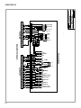
In addition to the terminal strips shown in Figure
2-10, the I/O Box also contains a pre-wired
temperature transmitter which receives inlet air
temperature sensor readings and transmits this
signal to the variable frequency drive (VFD)
contained in the Benchmark 3.0 Dual-Fuel
Boiler. The VFD utilizes this input signal to
adjust the rotation speed of the blower.
Figure 2-10.
Input/Output (I/O) Box Location
Brief descriptions of each mode of operation,
and their wiring requirements, are provided in
the following paragraphs. Additional information
concerning field wiring is provided in paragraphs
2.9.1 through 2.9.9. Refer to Chapter 5 for
detailed information on the available modes of
operation.
OUTDOOR SENSOR IN
SENSOR COMMON
AUX SENSOR IN
REMOTE INTL'K IN
EXHAUST SWITCH IN
DELAYED INTL'K IN
NOT USED
NOT USED
NC
COM
NO
+
ANALOG IN +
B.M.S. (PWM) IN -
NC
COM
NO
RS-485
COMM.
NOT USED
AUX RELAY
120 VAC, 5A, RES
NOT USED
SHIELD
mA OUT
FAULT RELAY
120 VAC, 5A, RES
+
+
G
-
RELAY CONTACTS:
120 VAC, 30 VDC
5 AMPS RESISTIVE
DANGER
120 VAC USED
IN THIS BOX
Figure 2-11. I/O Box Terminal Strip
2-7
INSTALLATION
2.9.1 Constant Setpoint Mode
The Constant Setpoint Mode is used when it is
desired to have a fixed setpoint that does not
deviate. No wiring connections, other than AC
electrical power connections, are required for
this mode. However, if desired, fault monitoring
or enable/disable interlock wiring can be utilized
(see paragraphs 2.9.9.1 and 2.9.10).
Mode) or firing rate (Direct Drive Mode) of the
Boiler. These formats are:
• 4 to 20 mA/1 to 5 VDC
• 0 to 20 mA/0 to 5 VDC
• PWM – (Pulse Width Modulated signal. See
para. 2.10.4)
• Network (RS485 Modbus. See para. 2.10.7)
This mode of operation increases supply water
temperature, as outdoor temperatures decrease.
An outside air temperature sensor (AERCO Part
No. 122790) is required. The sensor MUST BE
wired to the I/O Box wiring terminals (see Figure
2-11). Refer to paragraph 2.10.1 for additional
information on outside air temperature sensor
installation.
While it is possible to control a boiler or boilers
using one of the previously described modes of
operation, it may not be the method best suited
for the application. Prior to selecting one of
these modes of operation, it is recommended
that you consult with your local AERCO
representative or the factory for the mode of
operation that will work best with your
application. For more information on wiring the
4 to 20 mA / 1to 5VDC or the 0 to 20 mA / 0 to 5
VDC, see paragraph 2.9.3.
2.9.3 Boiler Management System Mode
2.9.5 Combination Mode
2.9.2 Indoor/Outdoor Reset Mode
NOTE
NOTE
BMS Model 168 can utilize either pulse
width modulation (PWM) or RS485
Modbus signaling to the Boiler. BMS II
Model 5R5-384 can utilize only RS485
signaling to the Boiler.
Only BMS Model 168 can be utilized for
the Combination Mode, not the BMS II
(Model 5R5-384).
When using an AERCO Boiler Management
System (BMS), the field wiring is connected
between the BMS Panel and each Boiler’s I/O
Box terminal strip (Figure 2-11). Twisted
shielded pair wire from 18 to 22 AWG must be
utilized for the connections. The BMS Mode can
utilize either pulse width modulation (PWM)
signaling, or RS485 Modbus signaling. For PWM
signaling, connections are made from the
AERCO Boiler Management System to the
B.M.S. (PWM) IN terminals on the I/O Box
terminal strip. For RS485 Modus signaling,
connections are made from the BMS to the
RS485 COMM terminals on the I/O Box terminal
strip. Polarity must be maintained and the shield
must be connected only at the AERCO BMS.
The boiler end of the shield must be left floating.
For additional instructions, refer to Chapter 5,
paragraph 5.6 in this manual. Also, refer to GF108M (BMS Model 168) and GF-124 (BMS II
Model 5R5-384), BMS -Operations Guides.
With a Combination Mode unit, field wiring is
between the unit’s I/O Box wiring terminals, the
CCP (Combination Control Panel), and the BMS
Model 168 (Boiler Management System). The
wiring must be accomplished using twistedshielded pair wire from 18 to 22 AWG. Polarity
must be maintained. For further instructions and
wiring diagrams, refer to the GF-108 Boiler
Management System Operations Guide and the
CCP-1 data sheet.
2.10 I/O BOX CONNECTIONS
The types of input and output signals and
devices to be connected to the I/O Box terminals
shown in Figure 2-11 are described in the
following paragraphs.
CAUTION
DO NOT make any connections to the
I/O Box terminals labeled “NOT
USED”. Attempting to do so may
cause equipment damage.
2.9.4 Remote Setpoint and Direct Drive
Modes
2.10.1 OUTDOOR SENSOR IN
The Benchmark 3.0 Dual-Fuel Boiler can accept
several types of signal formats from an Energy
Management
System
(EMS),
Building
Automation System (BAS) or other source, to
control either the setpoint (Remote Setpoint
An outdoor air temperature sensor (AERCO Part
No. 122790) will be required primarily for the
Indoor/Outdoor reset mode of operation. It can
also be used with another mode if it is desired to
use the outdoor sensor enable/disable feature.
2-8
INSTALLATION
This feature allows the boiler to be enabled or
disabled based on the outdoor air temperature.
The factory default for the outdoor sensor is
DISABLED. To enable the sensor and/or select
an enable/disable outdoor temperature, see the
Configuration menu in Chapter 3.
signal source and the Boiler’s I/O Box must be
made using twisted shielded pair wire from 18 to
22 AWG, such as Belden 9841 (see Figure
2-11). Polarity must be maintained. The shield
must be connected only at the source end and
must be left floating (not connected) at the
Boiler’s I/O Box.
The outdoor sensor may be wired up to 200 feet
from the boiler.
It is connected to the
OUTDOOR SENSOR IN and SENSOR
COMMON terminals in the I/O Box (see Figures
2-10 and 2-11). Wire the sensor using a twisted
shielded pair wire from 18 to 22 AWG. There is
no polarity to observe when terminating these
wires. The shield is to be connected only to the
terminals labeled SHIELD in the I/O Box. The
sensor end of the shield must be left free and
ungrounded.
Regardless of whether voltage or current is used
for the drive signal, they are linearly mapped to
a 40°F to 240°F setpoint or a 0% to 100% firing
rate. No scaling for these signals is provided
When mounting the sensor, it must be located
on the North side of the building where an
average outside air temperature is expected.
The sensor must be shielded from direct sunlight
as well as impingement by the elements. If a
shield is used, it must allow for free air
circulation.
These terminals are used to connect the
AERCO Boiler Management System (BMS)
Model 168 to the unit. The BMS Model 168
utilizes a 12 millisecond, ON/OFF duty cycle.
This duty cycle is Pulse Width Modulated (PWM)
to control firing rate. A 0% firing rate = a 5% ON
pulse and a 100% firing rate = a 95% ON pulse.
2.10.2 AUX SENSOR IN
2.10.5 SHIELD
The AUX SENSOR IN terminals can be used to
add an additional temperature sensor for
monitoring purposes. This input is always
enabled and is a view-only input that can be
seen in the Operating Menu. The sensor must
be wired to the AUX SENSOR IN and SENSOR
COMMON terminals and must be similar to
AERCO BALCO wire sensor Part No. 12449. A
resistance chart for this sensor is provided in
Appendix C.
The SHIELD terminals are used to terminate any
shields used on sensor wires connected to the
unit. Only shields must be connected to these
terminals.
2.10.3 ANALOG IN
2.10.7 RS-485 COMM
The ANALOG IN + and – terminals are used
when an external signal is used to drive the
firing rate (Direct Drive Mode) or change the
setpoint (Remote Setpoint Mode) of the Boiler.
These terminals are used for RS-485 MODBUS
serial communication between the unit and an
external “Master” such as a Boiler Management
System (BMS), Energy Management System
(EMS), Building Automation System (BAS) or
other suitable device.
Either a 4 to 20 mA /1 to 5 VDC or a 0 to 20 mA
/ 0 to 5 VDC signal may be used to vary the
setpoint or firing rate. The factory default setting
is for 4 to 20 mA / 1 to 5 VDC, however this may
be changed to 0 to 20 mA / 0 to 5 VDC using the
Configuration Menu described in Chapter 3. If
voltage rather than current is selected as the
drive signal, a DIP switch must be set on the
CPU Board located inside the Control Box.
Contact the AERCO factory for information on
setting DIP switches.
All of the supplied signals must be floating
(ungrounded) signals. Connections between the
2.10.4 B.M.S. (PWM) IN
NOTE
Only BMS Model 168 can utilize Pulse
Width Modulation (PWM), not the BMS II
(Model 5R5-384).
2.10.6 mA OUT
These terminals provide a 4 to 20 mA output to
the VFD to control the rotational speed of the
blower. This function is enabled in the
Configuration Menu (Chapter 3, Table 3.4).
2.10.8 EXHAUST SWITCH IN
These terminals permit an external exhaust
switch to be connected to the exhaust manifold
of the boiler. The exhaust switch should be a
normally open type switch (such as AERCO Part
No. 123463) that closes (trips) at 500°F.
2.10.9 INTERLOCKS
The unit offers two interlock circuits for
interfacing with Energy Management Systems
and auxiliary equipment such as pumps or
2-9
INSTALLATION
louvers. These interlocks are called the Remote
Interlock and Delayed Interlock (Figure 2-11).
The wiring terminals for these interlocks are
located inside the I/O Box on the unit front
panel. The I/O Box cover contains a wiring
diagram which shows the terminal strip locations
for these interlocks (REMOTE INTL’K IN and
DELAYED INTL’K IN). Both interlocks,
described below, are factory wired in the closed
position.
NOTE
Both the Delayed Interlock and Remote
Interlock MUST be in the closed position
to allow the unit to fire.
2.10.9.1 REMOTE INTERLOCK IN
The remote interlock circuit is provided to
remotely start (enable) and stop (disable) the
Boiler, if desired.
The circuit is labeled
REMOTE INTL’K IN and is located inside the I/O
Box on the front panel. The circuit is 24 VAC
and is factory pre-wired in the closed (jumpered)
position.
2.10.9.2 DELAYED INTERLOCK IN
The delayed interlock is typically used in
conjunction with the auxiliary relay described in
paragraph 2.10. This interlock circuit is located
in the purge section of the start string. It can be
connected to the proving device (end switch,
flow switch etc.) of an auxiliary piece of
equipment started by the Boiler’s auxiliary relay.
The delayed interlock must be closed for the
boiler to fire.
If the delayed interlock is connected to a proving
device that requires time to close (make), a time
delay (Aux Start On Dly) that holds the start
sequence of the boiler long enough for a proving
switch to make can be programmed. Should the
proving switch not prove within the programmed
time frame, the boiler will shut down. The Aux
Start On Dly can be programmed from 0 to 120
seconds.
This option is locate in the
Configuration Menu (Chapter 3, Table 3-4).
2.10.10 FAULT RELAY
The fault relay is a single pole double throw
(SPDT) relay having a normally open and
normally closed set of relay contacts that are
rated for 5 amps at 120 VAC and 5 amps at 30
VDC. The relay energizes when any fault
condition occurs and remains energized until the
fault is cleared and the CLEAR button is
depressed. The fault relay connections are
shown in Figure 2-11.
2-10
2.11 AUXILIARY RELAY CONTACTS
Each Boiler is equipped with a single pole
double throw (SPDT) relay that is energized
when there is a demand for heat and deenergized after the demand for heat is satisfied.
The relay is provided for the control of auxiliary
equipment, such as pumps and louvers, or can
be used as a Boiler status indictor (firing or not
firing). Its contacts are rated for 120 VAC @ 5
amps. Refer to Figure 2-11 to locate the AUX
RELAY terminals for wiring connections.
2.12 FLUE GAS VENT INSTALLATION
The minimum allowable vent diameter for a
single Benchmark 3.0 Dual-Fuel Boiler is 8
inches.
The
AERCO
Benchmark
Venting
and
Combustion Air Guide, GF-3050, must be
consulted before any flue gas vent or inlet air
venting is designed or installed. U/L listed,
positive pressure, watertight vent materials as
specified in AERCO’s GF-3050, must be used
for safety and code compliance. Since the unit is
capable of discharging low temperature exhaust
gases, horizontal sections of the flue vent
system must be pitched back to the unit a
minimum of 1/4 inch per foot to avoid
condensate pooling and allow for proper
drainage.
The combined pressure drop of vent and
combustion air systems must not exceed 140
equivalent feet of 8 inch ducting. Fittings as well
as pipe lengths must be calculated as part of the
equivalent length.
For a natural draft installation the draft must not
exceed ±0.25 inch W.C. These factors must be
planned into the vent installation. If the
maximum allowable equivalent lengths of piping
are exceeded, the unit will not operate properly
or reliably.
2.13 COMBUSTION AIR
The
AERCO
Benchmark
Venting
and
Combustion Air Guide, GF-3050 MUST be
consulted before any flue or combustion supply
air venting is designed or implemented.
Combustion air supply is a direct requirement of
ANSI 223.1, NFPA-54, and local codes. These
codes should be consulted before a permanent
design is determined.
INSTALLATION
The combustion air must be free of chlorine,
halogenated hydrocarbons, or other chemicals
that can become hazardous when used in gasfired equipment. Common sources of these
compounds are swimming pools, degreasing
compounds, plastic processing and refrigerants.
Whenever the environment contains these types
of chemicals, combustion air must be supplied
from a clean area outdoors for the protection
and longevity of the equipment.
The AERCO Benchmark 3.0 Dual-Fuel Boiler is
UL listed for 100% sealed combustion. It can
also be installed using room air, provided there
is an adequate supply. (See paragraph 2.13.3
for more information concerning sealed
combustion air). If the sealed combustion air
option is not being used, an inlet screen will be
attached at the air inlet on the top of the unit
The more common methods of supplying
combustion air are outlined below. For more
information concerning combustion air, consult
the
AERCO
Benchmark
Venting
and
Combustion Air Guide, GF-3050.
2.13.1 Combustion Air From Outside the
Building
2.13.2 Combustion Air From Inside The
Building
When combustion air is provided from within the
building, it must be supplied through two
permanent openings in an interior wall. Each
opening must have a free area of not less than
one square inch per 1000 BTU/H of total boiler
input. The free area must take into account any
restrictions such as louvers.
2.13.3 Sealed Combustion
The AERCO Benchmark 3.0 Dual-Fuel Boiler is
UL listed for 100%-sealed combustion. For
sealed combustion installations, the screen on
the air inlet duct of the unit must be removed.
The inlet air ductwork must then be attached
directly to the unit’s air inlet.
In a sealed combustion air application, the
combustion air ducting pressure losses must be
taken into account when calculating the total
maximum allowable venting run. See the
AERCO Benchmark Venting and Combustion
Air Guide, GF-3050. When using the boiler in a
sealed combustion air configuration, each unit
must have a minimum 8 inch diameter
connection at the unit.
Air supplied from outside the building must be
provided through two permanent openings. Each
opening must have a free area of not less than
one square inch for each 4000 BTU/H boiler
input. The free area must take into account
restrictions such as louvers and bird screens.
2-11
CONTROL PANEL OPERATING PROCEDURES
CHAPTER 3
CONTROL PANEL OPERATING PROCEDURES
3.1 INTRODUCTION
The information in this Chapter provides a guide
to the operation of the Benchmark 3.0 Dual-Fuel
Boiler using the Control Panel mounted on the
front of the unit. It is imperative that the initial
startup of this unit be performed by factory
trained personnel. Operation prior to initial
startup by factory trained personnel will void the
equipment warranty. In addition, the following
WARNINGS and CAUTIONS must be observed
at all times.
2
1
CAUTION
All of the installation procedures in
Chapter 2 must be completed before
attempting to start the unit.
3
4
12
5
WARNING
ELECTRICAL VOLTAGES IN THIS
SYSTEM MAY INCLUDE 460, 208
AND 24 VOLTS AC. IT MUST BE
SERVICED ONLY BY FACTORY
CERTIFIED
SERVICE
TECHNICIANS.
11
6
10
7
8
WARNING
DO NOT ATTEMPT TO DRY FIRE
THE BOILER. STARTING THE UNIT
WITHOUT A FULL WATER LEVEL
CAN SERIOUSLY DAMAGE THE
UNIT AND MAY RESULT IN INJURY
TO PERSONNEL OR PROPERTY
DAMAGE. THIS SITUATION WILL
VOID ANY WARRANTY.
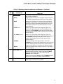
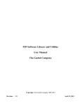
3.2 CONTROL PANEL DESCRIPTION
The Control Panel shown in Figure 3-1 contains
all of the controls, indicators and displays
necessary to operate, adjust and troubleshoot
the Benchmark 3.0 Dual-Fuel Boiler. These
operating controls, indicators and displays are
listed and described in Table 3-1. Additional
information on these items are provided in the
individual operating procedures provided in this
Chapter.
9
Figure 3-1.
Control Panel Front View
3-1
CONTROL PANEL OPERATING PROCEDURES
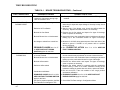
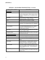
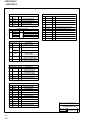
Table 3-1 Operating Controls, Indicators and Displays
ITEM
NO.
1
CONTROL, INDICATOR
OR DISPLAY
LED Status Indicators
FUNCTION
Four Status LEDs indicate the current operating status as
follows:
COMM
Lights when RS-232 communication is occurring
MANUAL
Lights when the unit is being controlled using the front panel
keypad
REMOTE
Lights when the unit is being controlled by an external signal
from an Energy Management System
DEMAND
Lights when there is a demand for heat
2
OUTLET
TEMPERATURE
Display
3–Digit, 7–Segment LED display continuously displays the
outlet water temperature. The °F or °C LED next to the
display lights to indicate whether the displayed temperature is
in degrees Fahrenheit or degrees Celsius.
3
VFD Display
Vacuum Fluorescent Display (VFD) consists of 2 lines each
capable of displaying up to 16 alphanumeric characters. The
information displayed includes:
Startup Messages
Fault Messages
Operating Status Messages
Menu Selection
4
RS-232 Port
Port permits a Laptop Computer or External Modem to be
connected to the unit’s Control Panel.
5
FAULT Indicator
Red FAULT LED indicator lights when a boiler alarm
condition occurs. An alarm message will appear in the VFD.
6
CLEAR Key
Turns off the FAULT indicator and clears the alarm message
if the alarm is no longer valid. Lockout type alarms will be
latched and cannot be cleared by simply pressing this key.
Troubleshooting may be required to clear these types of
alarms.
7
READY Indicator
Lights ON/OFF switch is set to ON and all Pre-Purge
conditions have been satisfied.
8
ON/OFF Switch
Enables and disables boiler operation.
9
LOW WATER LEVEL
Allows operator to test operation of the water level monitor.
TEST/RESET Switches
Pressing TEST opens the water level probe circuit and
simulates a Low Water Level alarm.
Pressing RESET resets the water level monitor circuit.
Pressing the CLEAR key (item 6) resets the display.
3-2
CONTROL PANEL OPERATING PROCEDURES
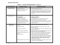
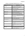
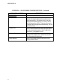
Table 3-1 Operating Controls, Indicators and Displays – Continued
ITEM
NO.
10
11
CONTROL, INDICATOR
OR DISPLAY
MENU Keypad
FUNCTION
Consists of 6 keys which provide the following functions for
the Control Panel Menus:
MENU
Steps through the main menu categories shown in Figure 32. The Menu categories wrap around in the order shown.
BACK
Allows you to go back to the previous menu level without
changing any information. Continuously pressing this key
will bring you back to the default status display in the VFD.
Also, this key allows you to go back to the top of a main
menu category.
▲ (UP) Arrow
When in one of the main menu categories (Figure 3-2),
pressing the ▲ arrow key will select the displayed menu
category. If the CHANGE key was pressed and the menu
item is flashing, pressing the ▲ arrow key will increment the
selected setting.
▼ (DOWN) Arrow
When in one of the main menu categories (Figure 3-2),
pressing this key will select the displayed menu category. If
the CHANGE key was pressed and the menu item is
flashing, pressing the ▼ arrow key will decrement the
selected setting.
CHANGE
Permits a setting to be changed (edited). When the
CHANGE key is pressed, the displayed menu item will begin
to flash. Pressing the ▲ or ▼ arrow key when the item is
flashing will increment or decrement the displayed setting.
ENTER
Saves the modified menu settings in memory. The display
will stop flashing.
AUTO/MAN Switch
This switch toggles the boiler between the Automatic and
Manual modes of operation. When in the Manual (MAN)
mode, the front panel controls are enabled and the
MANUAL status LED lights.
When in the Automatic (AUTO) mode, the MANUAL status
LED will be off and the front panel controls disabled.
12
FIRE RATE Bargraph
20 segment red LED bargraph continuously shows the Fire
Rate in 5% increments from 0 to 100%.
3-3
CONTROL PANEL OPERATING PROCEDURES
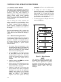
3.3 CONTROL PANEL MENUS
The Control Panel incorporates an extensive
menu structure which permits the operator to set
up, and configure the unit. The menu structure
consists of four major menu categories as
shown in Figure 3-2. Each of the menus shown,
contain options which permit operating
parameters to be viewed or changed. The
menus are protected by a password to prevent
unauthorized use.
Prior to entering the correct password, the
options contained in the Operating, Setup,
Configuration and Tuning Menu categories can
be viewed. However, with the exception of
Internal Setpoint Temperature (Configuration
Menu), none of the viewable menu options can
be changed.
around after the first or last available option
is reached.
6. To change the value or setting of a
displayed menu option, press the CHANGE
key. The displayed option will begin to flash.
Press the ▲ or ▼ arrow key to scroll
through the available menu option choices
for the option to be changed. The menu
option choices do not wrap around.
7. To select and store a changed menu item,
press the ENTER key.
Once the valid password (159) is entered, the
options listed in the Setup. Configuration and
Tuning Menus can be viewed and changed, if
desired.
3.3.1
Menu Processing Procedure
Accessing and initiating each menu and option
is accomplished using the Menu Keys shown in
Figure 3-1. Therefore, it is imperative that you
be thoroughly familiar with the following basic
steps before attempting to perform specific
menu procedures.
1. The Control Panel will normally be in the
Operating Menu and the VFD will display the
current unit status. Pressing the ▲ or ▼
arrow key will display the other available
data items in the Operating Menu.
2. Press the MENU key. The display will show
the Setup Menu, which is the next menu
category shown in Figure 3-2. This menu
contains the Password option which must be
entered if other menu options will be
changed.
3. Continue pressing the MENU key until the
desired menu is displayed.
4. With the desired menu displayed, press the
▲ or ▼ arrow key. The first option in the
selected menu will be displayed.
5. Continue to press the ▲ or ▼ arrow key
until the desired menu option is displayed.
Pressing the ▲ arrow key will display the
available menu options in the Top-Down
sequence. Pressing the ▼ arrow key will
display the options in the Bottom-Up
sequence. The menu options will wrap3-4
Figure 3-2. Menu Structure
NOTE
The following paragraphs provide brief
descriptions of the options contained in each
menu. Refer to Appendix A for detailed
descriptions of each menu option. Refer to
Appendix B for listings and descriptions of
displayed startup, status and error
messages.
CONTROL PANEL OPERATING PROCEDURES
3.4 OPERATING MENU
The Operating Menu displays a number of key
operating parameters for the unit as listed in
Table 3-2. This menu is “Read-Only” and does
not allow personnel to change or adjust any
displayed items. Since this menu is “Read-Only”,
it can be viewed at any time without entering a
password. Pressing the ▲ arrow key to display
the menu items in the order listed (Top-Down).
Pressing the ▼ arrow key will display the menu
items in reverse order (Bottom-Up).
3.5 SETUP MENU
The Setup Menu (Table 3-3) permits the
operator to enter the unit password (159) which
is required to change the menu options. To
prevent unauthorized use, the password will
time-out after 1 hour. Therefore, the correct
password must be reentered when required. In
addition to permitting password entries, the
Setup Menu is also used to enter date and time,
units of temperature measurements and entries
required for external communication and control
of the unit via the RS-232 port. A view-only
software version display is also provided to
indicate the current Control Box software
version.
NOTE
The Outdoor Temp display item shown with
an asterisk in Table 3-2 will not be displayed
unless the Outdoor Sensor function has
been enabled in the Configuration Menu
(Table 3-4).
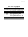
Table 3-2. Operating Menu
Menu Item Display
Available Choices or Limits
Minimum
Maximum
Default
Status Message
Active Setpoint
40°F
240°F
Aux Temp
30°F
245°F
Outdoor Temp*
-70°F
130°F
Fire Rate In
0%
Max Fire Rate
Flame Strength
0%
100%
Run Cycles
0
999,999
Run Hours
0
999,999
Fault Log
0
9
0
Table 3-3. Setup Menu
Menu Item Display
Passsword
Available Choices or Limits
Minimum
Maximum
0
Language
9999
English
12:00 am
11:59 pm
Date
01/01/00
12/31/99
Comm Address
Baud Rate
Software
Fahrenheit or Celsius
0
127
2400, 4800, 9600, 19.2K
Ver 0.00
0
English
Time
Unit of Temp
Default
Fahrenheit
0
9600
Ver 9.99
3-5
CONTROL PANEL OPERATING PROCEDURES
3.6 CONFIGURATION MENU
NOTE
The Configuration Menu shown in Table 3-4
permits adjustment of the Internal Setpoint
(Setpt) temperature regardless of whether the
valid password has been entered. Setpt is
required for operation in the Constant Setpoint
mode. The remaining options in this menu
require the valid password to be entered, prior to
changing existing entries. This menu contains a
number of other configuration settings which
may or may not be displayed, depending on the
current operating mode setting.
The Configuration Menu settings shown in
Table 3-4 are Factory-Set in accordance
with the requirements specified for each
individual order. Therefore, under normal
operating conditions, no changes will be
required.
Table 3-4. Configuration Menu
Menu Item Display
Internal Setpt
3-6
Available Choices or Limits
Minimum
Maximum
Lo Temp Limit
Hi Temp Limit
Default
130°F
Unit Type
Boiler or Water Heater
Boiler
Unit Size
0.5 MBTU, 1.0 MBTU
1.5 MBTU, 2.0 MBTU
2.5 MBTU, 3.0 MBTU
1.0 MBTU
Boiler Mode
Constant Setpoint,
Remote Setpoint,
Direct Drive
Combination
Outdoor Reset
Constant
Setpoint
Remote Signal
(If Mode = Remote
Setpoint, Direct Drive
or Combination)
4 – 20 mA/1 – 5V
0 -20 mA/0 – 5V
PWM Input (BMS)
Network
4 – 20 mA,
1-5V
Bldg Ref Temp
(If Mode = Outdoor
Reset)
40°F
230°F
70°F
Reset Ratio
(If Mode = Outdoor
Reset)
0.1
9.9
1.2
Outdoor Sensor
Enabled or Disabled
Disabled
System Start Tmp
(If Outdoor Sensor =
Enabled)
30°F
100°F
60°F
Setpt Lo Limit
40°F
Setpt Hi Limit
60°F
Setpt Hi Limit
Setpt Lo Limit
220°F
200°F
Temp Hi Limit
40°F
240°F
210°F
Max Fire Rate
40%
100%
100%
Pump Delay Timer
0 min.
30 min.
0 min.
Aux Start On Dly
0 sec.
120 sec.
0 sec.
CONTROL PANEL OPERATING PROCEDURES
Table 3-4. Configuration Menu - Continued
Available Choices or Limits
Minimum
Maximum
Default
Shutdown or Constant Setpt
Shutdown
*mA Output
(See CAUTION)
Setpoint, Outlet Temp,
Fire Rate Out, Off
*Fire Rate
Out
Low Fire Timer
2 sec.
Menu Item Display
Failsafe Mode
120 sec.
Setpt Limiting
Enabled or Disabled
Setpt Limit Band
0°F
10°F
2 sec.
Disabled
5°F
*CAUTION: DO NOT CHANGE mA Output Menu Item from its Default setting.
3.7 TUNING MENU
The Tuning Menu items in Table 3-5 are Factory set for each individual unit. Do not change these menu
entries unless specifically requested to do so by Factory-Trained personnel.
Table 3-5. Tuning Menu
Menu Item Display
Available Choices or Limits
Minimum
Maximum
Default
Prop Band
1°F
120°F
70°F
Integral Gain
0.00
2.00
1.00
0.0 min
2.00 min
0.00 min
Derivative Time
Reset Defaults?
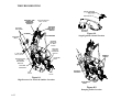
3.8 START SEQUENCE
When the Control Box ON/OFF switch is set to
the ON position, it checks all pre-purge safety
switches to ensure they are closed. These
switches include:
• Safety Shut-Off Valve Proof of Closure
(POC) switch
• Low Water Level switch
Yes
No
Are You Sure?
No
When there is a demand for heat, the following
events will occur:
NOTE
If any of the Pre-Purge safety device
switches are open, the appropriate fault
message will be displayed.
Also, the
appropriate fault messages will be displayed
throughout the start sequence, if the
required conditions are not observed.
• High Water Temperature switch
• High Gas Pressure switch
1. The DEMAND LED status indicator will light.
• Low Gas Pressure switch
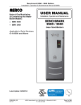
2. The unit checks to ensure that the Proof of
Closure (POC) switch in the Safety Shut-Off
Valve (SSOV) is closed. See Figure 3-3 for
SSOV locations.
• Blower Proof switch
If all of the above switches are closed, the
READY light above the ON/OFF switch will light
and the unit will be in the Standby mode.
3-7
CONTROL PANEL OPERATING PROCEDURES
NATURAL
GAS SSOV
PROPANE
SSOV
AIR IN
TO
AIR/FUEL
VALVE
TO BLOWER
DIAL
(DETAIL “A”)
STEPPER
MOTOR
NATURAL
GAS INLET
100
PROPANE
INLET
DETAIL “A”
Figure 3-4.
Air/Fuel Valve In Purge Position
Figure 3-3.
SSOV Locations
3.
With all required safety device switches
closed, a purge cycle will be initiated and the
following events will occur:
(a) The Blower relay energizes and turns
on blower.
(b) The Air/Fuel Valve rotates to the fullopen purge position and closes purge
position switch. The dial on the Air/Fuel
Valve (Figure 3-4) will read 100 to
indicate that it is full-open (100%).
(c) The FIRE RATE bargraph
100%.
will show
4. Next, the blower proof switch on the Air/Fuel
Valve (Figure 3-5) closes. The display will
show Purging and indicate the elapsed time
of the purge cycle in seconds. The normal
(default) time for the purge cycle is 10
seconds.
3-8
Figure 3-5.
Blower Proof Switch
CONTROL PANEL OPERATING PROCEDURES
5. Upon completion of the purge cycle, the
Control Box initiates an ignition cycle and
the following events occur:
DIAL
(DETAIL “A”)
(a) The Air/Fuel Valve rotates to the lowfire ignition position and closes the
ignition switch. The dial on the Air/Fuel
Valve (Figure 3-6) will read between 25
and 35 to indicate that the valve is in
the low-fire position.
(b) The igniter relay is activated and
provides ignition spark.
(c) The staged ignition solenoid valve is
energized (opened) allowing gas to flow
to the staged ignition piece.
STEPPER
MOTOR
(d) The gas Safety Shut-Off Valve (SSOV)
is energized (opened) allowing gas to
flow into the Air/Fuel Valve.
25
6. Up to 7 seconds will be allowed for ignition
to be detected. The igniter relay will be
turned off one second after flame is
detected.
7. After 2 seconds of continuous flame, Flame
Proven will be displayed and the flame
strength will be indicated. After 5 seconds,
the current date and time will be displayed in
place of the flame strength.
8. With the unit firing properly, it will be
controlled by the temperature controller
circuitry. The boiler’s FIRE RATE will be
continuously displayed on the front panel
bar graph.
Once the demand for heat has been satisfied,
the Control Box will turn off the dual SSOV gas
valves. The blower relay will be deactivated and
the Air/Fuel Valve will be closed. Standby will
be displayed.
DETAIL “A”
Figure 3-6.
Air/Fuel Valve In Ignition
3.9 START/STOP LEVELS
The start and stop levels are the fire rate
percentages that start and stop the unit, based
on load. These levels are Factory preset as
follows:
Start Level: 20%
Stop Level: 18%
Normally, these settings should not require
adjustment.
3-9
INITIAL START-UP
CHAPTER 4
4.1 INITIAL START-UP REQUIREMENTS
The requirements for the initial start-up of the
Benchmark 3.0 Dual-Fuel Boiler consist of the
following:
•
•
•
•
•
Complete installation
Perform combustion calibration
Set proper controls and limits
Set up mode of operation (see Chapter 5)
Test safety devices (see Chapter 6)
Installation should be fully completed before
performing initial start-up; and the start-up must
be complete prior to putting the unit into service.
Starting a unit without the proper piping, venting,
or electrical systems can be dangerous and may
void the product warranty. The following start-up
instructions should be followed precisely in order
to operate the unit safely and at a high thermal
efficiency, with low flue gas emissions.
Initial unit start-up is to be performed ONLY by
AERCO factory trained start-up and service
personnel. After following the steps in this
chapter, it will be necessary to perform the Mode
of Operation settings in Chapter 5, and the
Safety Device Testing procedures in Chapter 6
to complete the initial unit start-up.
INITIAL START-UP
CAUTION
All applicable installation procedures
in Chapter 2 must be completed
before attempting to start the unit.
4.2 TOOLS AND INSTRUMENTATION
FOR COMBUSTION CALIBRATION
To properly perform combustion calibration, the
proper instruments and tools must be used and
correctly attached to the unit. The following
paragraphs outline the necessary tools and
instrumentation as well as their installation.
4.2.1 Required Tools & Instrumentation
The following tools and instrumentation are
necessary to perform combustion calibration of
the unit:
• Digital Combustion Analyzer: Oxygen
accuracy to ± 0.4%; Carbon Monoxide
(CO) and Nitrogen Oxide (NOx) resolution
to 1PPM.
• 16 inch W.C. manometer or equivalent
gauge and plastic tubing.
• 1/8 inch NPT-to-barbed fittings for use with
gas supply manometer or gauge.
• Small and large flat blade screwdrivers.
• Tube of silicone adhesive
An AERCO Gas Fired Startup Sheet, included
with each Benchmark Boiler, must be completed
for each unit for warranty validation and a copy
must be returned promptly to AERCO at:
AERCO International, Inc.
159 Paris Ave.
Northvale, NJ 07647
WARNING
DO NOT ATTEMPT TO DRY FIRE
THE BOILER. STARTING THE UNIT
WITHOUT A FULL WATER LEVEL
CAN SERIOUSLY DAMAGE THE
UNIT AND MAY RESULT IN INJURY
TO PERSONNEL OR PROPERTY
DAMAGE. THIS SITUATION WILL
VOID ANY WARRANTY.
4.2.2 Installing Gas Supply Manometer
The gas supply manometer is installed in the
gas train as follows:
1. Close the main manual gas supply shut-off
valve upstream of the unit.
2. Remove the front door and left side panels
from the boiler to access the gas train
components.
3. Remove the 1/8 inch NPT pipe plug from the
leak detection ball valve on the downstream
side of the Safety Shut Off Valve (SSOV) as
shown in Figure 4-1.
4. Install a NPT-to-barbed fitting into the
tapped plug port.
4-1
INITIAL START-UP
5. Attach one end of the plastic tubing to the
barbed fitting and the other end to the 16
inch W.C. manometer.
2. If necessary, adjust the stop on the
combustion analyzer probe so that it will
extend mid-way into the flue gas flow. DO
NOT install the probe at this time.
IMPORTANT
For Dual Fuel units, perform the natural
gas combustion calibration procedures in
para. 4.3 before performing the propane
combustion calibration procedures in
para. 4.4.
Refer to Appendix K for switchover
instructions when changing from Natural
Gas to Propane or from Propane to
Natural Gas.
4.3 NATURAL GAS COMBUSTION
CALIBRATION
Figure 4-1
1/8 Inch Gas Plug Location
4.2.3 Accessing the Vent Probe Port
The unit contains NPT plugs on both the left and
right side of the exhaust manifold at the rear of
the unit as shown in Figure 4-2. Prepare the port
for the combustion analyzer probe as follows:
1. Remove the plug from the probe port on the
left or right side of the exhaust manifold.
The Benchmark 3.0 Dual Fuel Boiler is
combustion calibrated at the factory prior to
shipping. However, recalibration as part of initial
start-up is necessary due to changes in the local
altitude, gas BTU content, gas supply piping and
supply regulators. Factory Test Data sheets are
shipped with each unit. These sheets must be
filled out and returned to AERCO for proper
Warranty Validation.
It is important to perform the following procedure
as outlined. This will keep readjustments to a
minimum and provide optimum performance.
1. Open the water supply and return valves to
the unit and ensure that the system pumps
are running.
2. Open the natural gas supply valve(s) to the
unit.
3. Set the control panel ON/OFF switch to the
OFF position.
4. Turn on external AC power to the unit. The
display will show LOSS OF POWER and the
time and date.
5. Set the unit to the Manual Mode by pressing
the AUTO/MAN key on the control panel. A
flashing Manual Fire Rate message will be
displayed with the present rate in %. Also,
the MANUAL LED will light.
6. Adjust the fire rate to 0% by pressing the ▼
arrow key.
Figure 4-2
Analyzer Probe Hole Location
4-2
7. Ensure that the leak detection ball valve
(Figure 4-1) downstream of the SSOV is
open.
INITIAL START-UP
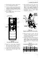
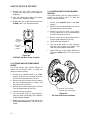
8. Ensure that the Fuel Selector Switch (Figure
4-3 is in the NATURAL GAS position.
9. Locate the Variable Frequency Drive (VFD)
on the front of the unit behind the panel door
(Figure 4-3). Insert the “LogicStick” with the
“NATURAL GAS” label in the slot on the
front of the VFD.
13. Next, increase the fire rate to 100%. Verify
that the gas pressure downstream of the
SSOV is 5” W.C. for both FM and IRI gas
trains. If gas pressure adjustment is
required, remove the brass hex head cap on
the SSOV (Figure 4-4). Make gas regulator
adjustments
using
a
short,
flat-tip
screwdriver to obtain 5” W.C.
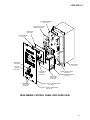
10. Set the ON/OFF switch on the unit control
panel to the ON position.
TRANSFORMER
(460 VAC UNITS ONLY)
POWER
BOX
CONTROL
PANEL
VFD
FUEL
SELECTOR
SWITCH
I/O BOX
Figure 4-4
Regulator Adjustment Screw Location
14. With the firing rate at 100%, insert the
combustion analyzer probe into the flue
probe opening and allow enough time for the
combustion analyzer to settle.
Figure 4-3
Front View With Door Removed
11. Access the control panel Configuration
Menu and ensure that the Max Fire Rate is
set to 100%. (Refer to Chapter 3, para. 3.3
for instructions on changing menu options).
12. Change the fire rate to 29% using the ▲
arrow key. The unit should begin its start
sequence and fire.
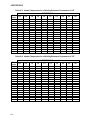
15. Compare the measured oxygen level to the
oxygen range for the inlet air temperature
shown in Table 4-1. Also, ensure that the
carbon monoxide (CO) and nitrogen oxide
(NOx) readings do not exceed the values
shown.
Table 4-1
Combustion Oxygen Levels for a 100%
Firing Rate
Inlet Air
Temp
>100°F
90°F
80°F
<70°F
Oxygen %
± 0.2
4.8 %
5.0 %
5.2 %
5.3 %
Carbon
Monoxide
<100 ppm
<100 ppm
<100 ppm
<100 ppm
NOx
<30 ppm
<30 ppm
<30 ppm
<30 ppm
4-3
INITIAL START-UP
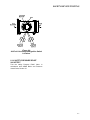
16. If necessary, adjust the iris air damper
shown in Figure 4-5 until the oxygen level is
within the range specified in Table 4-1.
17. Once the oxygen level is within the specified
range at 100%, lower the firing rate to 70%.
Figure 4-6
VFD Controls and Displays
IMPORTANT
In the following steps, the values
appearing in the right part of the VFD
display for parameters 65, 64, 63, 62, 61
represent the base frequency (Hz) x 10.
For example: a displayed value of 528
corresponds to a frequency of 52.8 Hz.
19. Press the M (Menu) programming key on
the VFD.
20. Using the up (Λ) arrow key, select VFD
parameter 65. The selected parameter will
appear in the left part of the display and the
frequency (Hz) will appear in the right part of
the display (see IMPORTANT note above).
Figure 4-5
Iris Air Damper Location/Adjustment
NOTE
The remaining combustion calibration
steps utilize the Variable Frequency Drive
(VFD) located behind the front door of the
unit. The VFD up (Λ) and down (V) arrow
keys will be used to adjust the oxygen
level (%) at firing rates of 85%, 65%,
45%, 30% and 18% as described in the
following steps.
18. Locate the Variable Frequency Drive (VFD)
behind the front door of the unit (Figure 4-3).
Refer to the VFD operating controls shown
in Figure 4-6.
4-4
21. With the selected VFD parameter display
flashing, press the M key. Code will be
displayed, requesting the valid code to be
entered. Enter code 59 using the arrow
keys. Press the M key again to store the
valid code.
22. With parameter 65 displayed in the left part
of the VFD display, observe the oxygen level
(%) on the Combustion Analyzer. The
oxygen level at the 85% firing rate should be
as shown in the following tabular listing.
Also, ensure that the carbon monoxide (CO)
and nitrogen oxide (NOx) readings do not
exceed the values shown.
Combustion Oxygen Level at
85% Firing Rate
Oxygen %
± 0.2
6.0 %
Carbon
Monoxide
<100 ppm
NOx
<30 ppm
INITIAL START-UP
23. If the oxygen level is not within the specified
range, adjust the level using the up (Λ) and
down (V) arrow keys on the VFD. Using the
up (Λ) arrow key will increase oxygen level
and the down (V) arrow key will decrease
the oxygen level.
24. Once the oxygen level is within the specified
range at 85%, lower the firing rate to 65%
and select VFD parameter 64. The oxygen
level at the 65% firing rate should be as
shown below.
Combustion Oxygen Level at
65% Firing Rate
Oxygen %
± 0.2
6.3 %
Carbon
Monoxide
<50 ppm
NOx
<20 ppm
25. Adjust the oxygen level as necessary to
obtain the required reading at the 65% firing
rate.
26. Next, set the firing rate to 45% and select
VFD parameter 63. The oxygen level at the
45% firing rate should be as shown below.
Combustion Oxygen Level at
45% Firing Rate
Oxygen %
± 0.2
6.5 %
Carbon
Monoxide
<50 ppm
NOx
<20 ppm
27. Adjust the oxygen level as necessary to
obtain the required reading at the 45% firing
rate.
28. Next, set the firing rate to 30% and select
VFD parameter 62. The oxygen level at the
30% firing rate should be as follows:
Combustion Oxygen Level at
30% Firing Rate
Oxygen %
± 0.2
5.6 %
Carbon
Monoxide
<50 ppm
NOx
<20 ppm
29. Adjust the oxygen level as necessary to
obtain the required reading at the 30% firing
rate.
30. Finally, reduce the firing rate to 18% and
select VFD parameter 61. The oxygen level
at the 18% firing rate should be as shown in
the following tabular listing:
Combustion Oxygen Level at
18% Firing Rate
Oxygen %
± 0.2
6.5 %
Carbon
Monoxide
<50 ppm
NOx
<20 ppm
31. Adjust the oxygen level as necessary to
obtain the required reading at the 18% firing
rate.
IMPORTANT
Repeat steps 20 through 31 until the VFD
does not require adjustment when
sequencing from 70% to 14%.
32. This completes the Natural Gas combustion
calibration procedures.
IMPORTANT
Refer to Appendix K for switchover
instructions when changing from Natural
Gas to Propane or from Propane to
Natural Gas.
4.4 PROPANE COMBUSTION
CALIBRATION
The Benchmark 3.0 Dual Fuel Boiler is
combustion calibrated at the factory prior to
shipping. Recalibration as part of initial start-up
is necessary due to changes in the local altitude,
gas BTU content, gas supply piping and supply
regulators. Factory Test Data sheets are
shipped with each unit. These sheets must be
filled out and returned to AERCO for proper
Warranty Validation.
It is important to perform the following procedure
as outlined. This will keep readjustments to a
minimum and provide optimum performance.
1. Open the water supply and return valves to
the unit and ensure that the system pumps
are running.
2. Open the propane supply valve(s) to the
unit.
3. Set the control panel ON/OFF switch to the
OFF position.
4. Turn on external AC power to the unit. The
display will show LOSS OF POWER and the
time and date.
5. Set the unit to the Manual Mode by pressing
the AUTO/MAN key. A flashing Manual Fire
Rate message will be displayed with the
present rate in %. Also, the MANUAL LED
will light.
4-5
INITIAL START-UP
6. Adjust the fire rate to 0% by pressing the ▼
arrow key.
7. Ensure that the leak detection ball valve
(Figure 4-1) downstream of the propane
SSOV is open.
8. Ensure that the Fuel Selector Switch (Figure
4-3 is in the PROPANE position.
9. Locate the Variable Frequency Drive (VFD)
on the front of the unit behind the panel door
(Figure 4-3). Insert the “LogicStick” with the
“PROPANE” label in the slot on the front of
the VFD.
10. Set the ON/OFF switch on the unit control
panel to the ON position.
11. Access the Control Panel Configuration
Menu and change the Max Fire Rate to
75%. (Refer to Chapter 3, para. 3.3 for
instructions on changing menu options).
12. Change the fire rate to 29% using the ▲
arrow key. The unit should begin its start
sequence and fire.
13. Next, increase the fire rate to 75%. Verify
that the gas pressure downstream of the
propane SSOV is 2.1” W.C. for both FM and
IRI gas trains. If gas pressure adjustment is
required, remove the brass hex head cap on
the propane SSOV (Figure 4-7). Make gas
regulator adjustments using a flat-tip
screwdriver to obtain 2.1” W.C.
14. With the firing rate at 75%, insert the
combustion analyzer probe into the flue
probe opening and allow enough time for the
combustion analyzer to settle.
NOTE
The combustion calibration steps utilize
the Variable Frequency Drive (VFD)
located behind the front door of the unit.
The VFD up (Λ) and down (V) arrow keys
will be used to adjust the oxygen level (%)
at firing rates of 75%, 60%, 45%, 30%
and 18% as described in the following
steps.
15. Locate the Variable Frequency Drive (VFD)
behind the front door of the unit (Figure 4-3).
Refer to the VFD operating controls shown
in Figure 4-6.
IMPORTANT
In the following steps, the values
appearing in the right part of the VFD
display for parameters 70, 69, 68, 67, 66
represent the base frequency (Hz) x 10.
For example: a displayed value of 528
corresponds to a frequency of 52.8 Hz.
16. Press the M (Menu) programming key on
the VFD.
17. Using the up (Λ) arrow key, select VFD
parameter 70. The selected parameter will
appear in the left part of the display and the
frequency (Hz) will appear in the right part of
the display (see IMPORTANT note above).
18. With the selected VFD parameter display
flashing, press the M key. Code will be
displayed, requesting the valid code to be
entered. Enter code 59 using the arrow
keys. Press the M key again to store the
valid code.
19. With parameter 70 displayed in the left part
of the VFD display, observe the oxygen level
(%) on the Combustion Analyzer. The
oxygen level at the 75% firing rate should be
as shown in the following tabular listing.
Also, ensure that the carbon monoxide (CO)
reading does not exceed the value shown.
Combustion Oxygen Level at
75% Firing Rate
Oxygen %
± 0.2
4.0 %
Figure 4-7
Regulator Adjustment Screw Location
4-6
Carbon
Monoxide
<100 ppm
INITIAL START-UP
20. If the oxygen level is not within the specified
range, adjust the level using the up (Λ) and
down (V) arrow keys on the VFD. Using the
up (Λ) arrow key will increase oxygen level
and the down (V) arrow key will decrease
the oxygen level.
21. Once the oxygen level is within the specified
range at 75%, lower the firing rate to 60%
and select VFD parameter 69. The oxygen
level at the 60% firing rate should be as
follows:
Combustion Oxygen Level at
60% Firing Rate
Oxygen %
± 0.2
5.5 %
Carbon
Monoxide
<50 ppm
22. Adjust the oxygen level as necessary to
obtain the required reading at the 60% firing
rate.
23. Next, set the firing rate to 45% and select
VFD parameter 68. The oxygen level at the
45% firing rate should be as shown below.
Combustion Oxygen Level at
45% Firing Rate
Oxygen %
± 0.2
5.0 %
Carbon
Monoxide
<100 ppm
24. Adjust the oxygen level as necessary to
obtain the required reading at the 45% firing
rate.
25. Next, set the firing rate to 30% and select
VFD parameter 67. The oxygen level at the
30% firing rate should be as follows:
Combustion Oxygen Level at
30% Firing Rate
Oxygen %
± 0.2
5.0 %
Carbon
Monoxide
<100 ppm
26. Adjust the oxygen level as necessary to
obtain the required reading at the 30% firing
rate.
27. Finally, reduce the firing rate to 18% and
select VFD parameter 66. The oxygen level
at the 18% firing rate should be as shown in
the following tabular listing:
Combustion Oxygen Level at
18% Firing Rate
Oxygen %
± 0.2
5.5 %
Carbon
Monoxide
<100 ppm
28. Adjust the oxygen level as necessary to
obtain the required reading at the 18% firing
rate.
IMPORTANT
Repeat steps 17 through 28 until the VFD
does not require adjustment when
sequencing from 75% to 18%.
29. This completes the Propane combustion
calibration procedures.
4.5 UNIT REASSEMBLY
Once the combustion calibration adjustments
are properly set for Natural Gas and Propane,
the unit can be reassembled for service
operation.
1. Access the Control Panel Configuration
Menu and ensure that the Max Fire Rate is
set to the desired level for the fuel being
used for service operation (100% for Natural
Gas; 75% for Propane).
2. Set the control panel ON/OFF switch to the
OFF position.
3. Disconnect AC power from the unit.
4. Shut off the gas supply to the unit.
5. Set the Fuel Selector Switch to the
corresponding position for the fuel being
used for service operation.
6. Install the correct VFD Logic Stick for the
fuel being used.
7. Remove the manometer and barbed fittings
and reinstall the NPT plug using a suitable
pipe thread compound.
8. Remove the combustion analyzer probe
from the vent hole. Replace the NPT plug in
the vent hole using a suitable pipe joint
compound.
9. Replace the unit’s side panels and front
door.
4-7
INITIAL START-UP
4.6 OVER-TEMPERATURE LIMIT
SWITCHES
The unit contains both automatic and manual
reset over-temperature limit switches. These
switches are mounted on a plate attached to the
boiler shell as shown in Figure 4-6. The switches
can be accessed by removing the left side
panels of the unit. The manual reset switch is
not adjustable and is permanently fixed at
210°F. This switch will shut down and lock out
the boiler if the water temperature exceeds
210°F. Following an over-temperature condition,
it must be manually reset by pressing the
RESET button before the boiler can be
restarted. The automatic reset over-temperature
switch is adjustable and allows the boiler to
restart, once the temperature drops below its
temperature setting. Set the automatic overtemperature switch to the desired setting.
Figure 4-6
Over Temperature Limit Switch
Locations
4-8
MODE OF OPERATION
CHAPTER 5
MODE OF OPERATION
5.1 INTRODUCTION
The Benchmark 3.0 Dual-Fuel Boiler is capable
of being operated in any one of six different
modes. The following paragraphs in this Chapter
provide descriptions of each of these operating
modes. Each Benchmark 3.0 Dual-Fuel Boiler is
shipped from the factory tested and configured
for the ordered mode of operation.
All
temperature related parameters are at their
factory default values which work well in most
applications. However, it may be necessary to
change certain parameters to customize the unit
to the system environment. A complete listing
and descriptions of the temperature related
parameters are included in Appendix A. Factory
defaults are listed in Appendix E. After reading
this chapter, parameters can be customized to
suit the needs of the specific application.
5.2 INDOOR/OUTDOOR RESET MODE
This mode of operation is based on outside air
temperatures. As the outside air temperature
decreases, the supply header temperature will
increase and vice versa. For this mode, it is
necessary to install an outside air sensor as well
as select a building reference temperature and a
reset ratio.
5.2.1 Reset Ratio
Reset ratio is an adjustable number from 0.1 to
9.9. Once adjusted, the supply header
temperature will increase by that number for
each degree that the outside air temperature
decreases. For instance, if a reset ratio of 1.6 is
used, for each degree that outside air
temperature decreases the supply header
temperature will increase by 1.6 degrees.
5.2.2 Building Reference Temperature
This is a temperature from 40°F to 230°F. Once
selected, it is the temperature that the system
references to begin increasing its temperature.
For instance, if a reset ratio of 1.6 is used, and
we select a building reference temperature of
70°F, then at an outside temperature of 69°F,
the supply header temperature will increase by
1.6° to 71.6°F.
5.2.3 Outdoor Air Temperature Sensor
Installation
The outdoor air temperature sensor must be
mounted on the North side of the building in an
area where the average outside air temperature
is expected. The sensor must be shielded from
the sun's direct rays, as well as direct
impingement by the elements. If a cover or
shield is used, it must allow free air circulation.
The sensor may be mounted up to two hundred
feet from the unit. Sensor connections are
made at the Input/Output (I/O) Box on the front
of the Benchmark 3.0 Dual-Fuel Boiler.
Connections are made at the terminals labeled
OUTDOOR SENSOR IN and SENSOR
COMMON inside the I/O Box. Use shielded 18
to 22 AWG wire for connections. A wiring
diagram is provided on the cover of the I/O Box.
Refer to Chapter 2, paragraph 2.9.1 for
additional wiring information.
5.2.4 Indoor/ Outdoor Startup
Startup in the Indoor/Outdoor Reset Mode is
accomplished as follows:
1. Refer to the Indoor/Outdoor reset ratio
charts in Appendix D.
2. Choose the chart corresponding to the
desired Building Reference Temperature.
3. Go down the left column of the chart to the
coldest design outdoor air temperature
expected in your area.
NOTE
A design engineer typically provides
design outdoor air temperature and
supply header temperature data
4. Once the design outdoor air temperature is
chosen, go across the chart to the desired
supply header temperature for the design
temperature chosen in step 3.
5. Next, go up that column to the Reset Ratio
row to find the corresponding reset ratio.
6. Access the Configuration Menu and scroll
through it until the display shows Bldg Ref
Temp. (Building Reference Temperature).
5-1
MODE OF OPERATION
7. Press the CHANGE key. The display will
begin to flash.
8. Use the ▲ and ▼ arrow keys to select the
desired Building Reference Temperature.
9. Press ENTER to save any changes.
10. Next, scroll through the Configuration Menu
until the display shows Reset Ratio.
11. Press the CHANGE key. The display will
begin to flash.
12. Use the ▲ and ▼ arrow keys to select the
Reset Ratio determined in step 5.
13. Press ENTER to save the change.
Refer to paragraph 3.3 for detailed instructions
on menu changing.
5.3 CONSTANT SETPOINT MODE
The Constant Setpoint mode is used when a
fixed header temperature is desired. Common
uses of this mode of operation include water
source heat pump loops, and indirect heat
exchangers for potable hot water systems or
processes.
No external sensors are required to operate in
this mode. While it is necessary to set the
desired setpoint temperature, it is not necessary
to change any other temperature-related
functions. The unit is factory preset with settings
that work well in most applications. Prior to
changing any temperature-related parameters,
other than the setpoint, it is suggested that an
AERCO representative be contacted.
For
descriptions of temperature-related functions
and their factory defaults, see Appendices A and
E.
The setpoint temperature of the unit is
adjustable from 40°F to 240°F. To set the unit
for operation in the Constant Setpoint Mode, the
following menu settings must be made in the
Configuration Menu:
SETTING
Boiler Mode
Constant Setpoint
Internal Setpt
Select desired setpoint
using ▲ and ▼ arrow
keys (40°F to 240°F)
Refer to paragraph 3.3 for detailed instructions
on changing menu options.
5-2
The unit’s setpoint can be remotely controlled by
an Energy Management System (EMS) or
Building Automation System (BAS). The Remote
Setpoint can be driven by a current or voltage
signal within the following ranges:
4-20 mA/1-5 Vdc
0-20 mA/0-5 Vdc
The factory default setting for the Remote
Setpoint mode is 4 - 20 mA/1 - 5 Vdc. With this
setting, a 4 to 20 mA/1 to 5 Vdc signal, sent by
an EMS or BAS, is used to change the unit's
setpoint. The 4 mA/1V signal is equal to a 40°F
setpoint while a 20 mA /5V signal is equal to a
240°F setpoint. When a 0 to 20 mA/0 to 5 Vdc
signal is used, 0 mA is equal to a 40°F setpoint.
In addition to the current and voltage signals
described above, the Remote Setpoint mode
can also driven by a RS485 Modbus Network
signal from an EMS or BAS.
The Remote Setpoint modes of operation can be
used to drive single as well as multiple units.
NOTE
If a voltage, rather than current signal is
used to control the remote setpoint, a DIP
switch adjustment must be made on the
PMC Board located in the Control Panel
Assembly. Contact your local AERCO
representative for details.
In order to enable the Remote Setpoint Mode,
the following menu setting must be made in the
Configuration Menu:
MENU OPTION
5.3.1 Setting the Setpoint
MENU OPTION
5.4 REMOTE SETPOINT MODES
SETTING
Boiler Mode
Remote Setpoint
Remote Signal
4-20mA/1-5V,
0-20mA/0-5V, or
Network
Refer to paragraph 3.3 for detailed instructions
on changing menu options.
MODE OF OPERATION
If the Network setting is selected for RS485
Modbus operation, a valid Comm Address must
be entered in the Setup Menu. Refer to Modbus
Communication Manual GF-114 for additional
information.
While it is possible to change the settings of
temperature related functions, the unit is factory
preset with settings that work well in most
applications. It is suggested that an AERCO
representative be contacted, prior to changing
any temperature related function settings. For
descriptions of temperature-related functions
and their factory defaults, refer to Appendices A
and E.
5.4.1 Remote Setpoint Field Wiring
The only wiring connections necessary for the
Remote Setpoint mode are connection of the
remote signal leads from the source to the unit’s
I/O Box. The I/O Box is located on the front
panel of the Benchmark 3. Dual-Fuel 0 Boiler.
For either a 4-20mA/0-5V or a 0-20mA/0-5V
setting, the connections are made at the
ANALOG IN terminals in the I/O Box. For a
Network setting, the connections are made at
the RS-485 COMM terminals in the I/O Box.
The signal must be floating, (ungrounded) at the
I/O Box and the wire used must be a two wire
shielded pair from 18 to 22 AWG. Polarity must
be observed. The source end of the shield must
be connected at the source. When driving
multiple units, each unit’s wiring must conform to
the above.
5.4.2 Remote Setpoint Startup
Since this mode of operation is factory preset
and the setpoint is being externally controlled,
no startup instructions are necessary. In this
mode, the REMOTE LED will light when the
external signal is present.
To operate the unit in the Manual mode, press
the AUTO/MAN switch. The REMOTE LED will
go off and the MANUAL LED will light.
To change back to the Remote Setpoint mode,
simply press the AUTO/MAN switch.
The
REMOTE LED will again light and the MANUAL
LED will go off.
5.5 DIRECT DRIVE MODES
The unit’s fire rate can be changed by a remote
signal which is typically sent from an Energy
Management System (EMS) or from a Building
Automation System (BAS). The Direct Drive
mode can be driven by a current or voltage
signal within the following ranges:
4-20 mA/1-5 Vdc
0-20 mA/0-5 Vdc
The factory default setting for the Direct Drive
mode is 4-20 mA/1-5 Vdc. With this setting, a 4
to 20 mA signal, sent by an EMS or BAS is used
to change the unit’s fire rate from 0% to 100%. A
4 mA/1V signal is equal to a 0% fire rate, while a
20 mA /5V signal is equal to a 100% fire rate.
When a 0-20 mA/0-5 Vdc signal is used, zero is
equal to a 0% fire rate.
In addition to the current and voltage signals
described above, the Direct Drive mode can also
driven by a RS485 Modbus Network signal from
an EMS or BAS.
When in a Direct Drive mode, the unit is a slave
to the EMS or BAS and does not have a role in
temperature control. Direct Drive can be used to
drive single, or multiple units.
NOTE
If a voltage, rather than current signal is
used to control the remote setpoint, a DIP
switch adjustment must be made on the
PMC Board located in the Control Box
Assembly. Contact your local AERCO
representative for details.
To enable the Direct Drive Mode, the following
menu setting must be made in the Configuration
Menu:
MENU OPTION
SETTING
Boiler Mode
Direct Drive
Remote Signal
4-20mA/1-5V,
0-20mA/0-5V, or
Network
Refer to paragraph 3.3 for instructions on
changing menu options.
5-3
MODE OF OPERATION
If the Network setting is selected for RS485
Modbus operation, a valid Comm Address must
be entered in the Setup Menu. Refer to Modbus
Communication Manual GF-114 for additional
information.
5.5.1 Direct Drive Field Wiring
The only wiring connections necessary for Direct
Drive mode are connection of the remote signal
leads from the source to the unit’s I/O Box. For
either a 4-20mA/0-5V or a 0-20mA/0-5V setting,
the connections are made at the ANALOG IN
terminals in the I/O Box. For a Network setting,
the connections are made at the RS-485 COMM
terminals in the I/O Box. The signal must be
floating, (ungrounded) at the I/O Box and the
wire used must be a two wire shielded pair from
18 to 22 AWG. Polarity must be observed. The
source end of the shield must be connected at
the source. When driving multiple units, each
unit’s wiring must conform to the above.
5.5.2 Direct Drive Startup
Since this mode of operation is factory preset
and the fire rate is being externally controlled, no
startup instructions are necessary. In this mode,
the REMOTE LED will light when the signal is
present.
To operate the unit in manual mode, press the
AUTO/MAN switch. The REMOTE LED will go
off and the MANUAL LED will light.
To change back to the Direct Drive mode, simply
press the AUTO/MAN switch. The REMOTE
LED will again light and the MANUAL LED will
go off.
5.6 BOILER MANAGEMENT SYSTEM
(BMS)
network communication. For BMS programming
and operation, see GF-108M (BMS Model 168)
and GF-124 (BMS II Model 5R5-384), BMS
Operations Guides. For operation via an RS485
Modbus
network,
refer
to
Modbus
Communication Manual GF-114.
To enable the BMS Mode, the following menu
settings must be made in the Configuration
Menu:
MENU OPTION
SETTING
Boiler Mode
Direct Drive
Remote Signal
BMS (PWM Input)
or
Network (RS485)
Refer to paragraph 3.3 for instructions on
changing menu options.
5.6.1 BMS External Field Wiring
Wiring connections for BMS control using PWM
signaling are made between connector JP2 on
the BMS panel (boilers 1 through 8), and the
B.M.S. (PWM) IN terminals in the I/O Box on the
front of the Benchmark 3.0 Dual-Fuel Boilers.
Refer to the wiring diagram provided on the
cover of the I/O Box.
Wiring connections for RS485 Modbus control
are made between connector JP11 on the BMS
(boilers 9 through 40) and the RS485 COMM
terminals in the I/O Box on the front of the
Benchmark 3.0 Dual-Fuel Boilers.
Wire the units using shielded twisted pair wire
between 18 and 22 AWG. Observe the proper
polarity for the B.M.S. (PWM) IN and/or RS485
COMM wiring connections. Shields should be
terminated only at the BMS and the boiler end
must be left floating. Each unit’s wiring must
conform to the above.
NOTE
BMS Model 168 can utilize either pulse
width modulation (PWM) or RS485
Modbus signaling to the Boiler. BMS II
Model 5R5-384 can utilize only RS485
signaling to the Boiler.
The BMS mode of operation is used in
conjunction with an AERCO Boiler Management
System. The BMS mode is used when it is
desired to operate multiple units in the most
efficient manner possible. The BMS can control
up to 40 boilers; 8 via pulse width modulation
(PWM) and up to 32 via Modbus (RS485)
5-4
5.6.2 BMS Setup and Startup
This mode of operation is factory preset and the
AERCO BMS controls the firing rate. There are
no setup instructions for each individual unit.
To operate the unit in manual mode, press the
AUTO/MAN switch. The REMOTE LED will go
off and the MANUAL LED will light
To change back to the BMS mode, simply press
the AUTO/MAN switch. The REMOTE LED will
again light and the MANUAL LED will go off.
MODE OF OPERATION
5.7 COMBINATION CONTROL SYSTEM
(CCS)
NOTE
Only BMS Model 168 can be utilized for
the Combination Mode, not the BMS II
(Model 5R5-384).
A Combination Control System (CCS) is one
that uses multiple boilers to cover both spaceheating and domestic hot water needs. An
AERCO Boiler Management System (BMS)
Model 168 and a Combination Control Panel
(CCP) are necessary to configure this system.
Typically, an adequate number of boilers are
installed to cover the space-heating load on the
design day, however one or more units are used
for the domestic hot water load.
The theory behind this type of system is that the
maximum space-heating load and the maximum
domestic hot water load do not occur simultaneously.+ Therefore, boilers used for the
domestic hot water are capable of switching
between constant setpoint and BMS modes of
operation. These boilers are the combination
units and are referred to as the combo boilers.
The combo boilers heat water to a constant
setpoint temperature. That water is then
circulated through a heat exchanger in a
domestic hot water storage tank.
When the space-heating load is such that all the
space-heating boilers are at 100% firing rate, the
BMS will then ask the Combination Control
Panel for the domestic boilers to become spaceheating boilers. Provided the domestic hot
water load is satisfied, the combo (hot water)
boilers will then become space-heating boilers.
If the domestic hot water load is not satisfied,
the combo boiler(s) remain on the domestic hot
water load. If the combo boilers switch over to
space heating, but there is a call for domestic
hot water, the CCP switches the combo units
back to the domestic load.
When the combo units are satisfying the
domestic load they are in constant setpoint
mode of operation. When the combo units
switch over to space heating, their mode of
operation changes to the BMS mode. For more
information concerning the operation of the
Combination Control Panel see the AERCO
CCP-1 literature.
5.7.1 Combination Control System Field
Wiring
Wiring for this system is between the BMS
Model 168 panel, the CCP and the B.M.S.
(PWM) IN terminals in the I/O Box. Wire the
units using a shielded twisted pair of 18 to 22
AWG wire. When wiring multiple units, each
unit’s wiring must conform to the above. For a
complete CCP system-wiring diagram see the
AERCO CCP-1 literature.
5.7.2 Combination Control System Setup
and Startup
Setup for the Combination Mode requires entries
to be made in the Configuration Menu for boiler
mode, remote signal type and setpoint. The
setpoint is adjustable from 40°F to 240°F.
Enter the following settings in the Configuration
Menu:
MENU OPTION
SETTING
Boiler Mode
Combination
Remote Signal
BMS (PWM Input)
Internal Setpt
40°F to 240°F
Refer to paragraph 3.3 for instructions on
changing menu options.
While it is possible to change other temperaturerelated functions for combination mode, thes
functions are preset to their factory default
values. These default settings work well in most
applications. It is suggested that AERCO be
contacted prior to changing settings other than
the unit’s setpoint. For a complete listing of
temperature related function defaults, see
Appendix E.
To set the unit to the manual mode, press the
AUTO/MAN switch. The MANUAL LED will
light.
To set the unit back to the auto mode, press the
AUTO/MAN switch. The MANUAL LED will go
off and the REMOTE LED will light.
When the boiler is switched to BMS mode, the
AERCO BMS controls the firing rate. There are
no setup requirements to the boiler(s) in this
mode
5-5
SAFETY DEVICE TESTING
CHAPTER 6 SAFETY DEVICE TESTING
6.1 TESTING OF SAFETY DEVICES
Periodic safety device testing is required to
ensure that the control system and safety
devices are operating properly. The Benchmark
3.0 Dual-Fuel control system comprehensively
monitors all combustion-related safety devices
before, during and after the start sequence. The
following tests check to ensure that the system
is operating as designed.
Operating controls and safety devices should be
tested on a regular basis or following service or
replacement. All testing must conform to local
codes such as ASME CSD-1.
3. Install a 0 – 16 “ W.C. manometer or a W.C.
gauge where the 1/8" plug was removed.
4. Slowly open the ball valve near the low gas
pressure switch.
5. Place the unit in Manual Mode and adjust
the firing rate between 25 and 30%.
6. While the unit is firing, slowly close the
external manual gas shut-off valve.
7. The unit should shut down and display a
LOW GAS PRESSURE fault message at
approximately 2.6” W.C. The FAULT indicator should also start flashing.
NOTE
MANUAL and AUTO modes of operation
are required to perform the following
tests. For a complete explanation of these
modes, see Chapter 3.
NOTE
It will be necessary to remove the front
door and side panels from the unit to
perform the following tests.
WARNING
ELECTRICAL VOLTAGES IN THIS
SYSTEM MAY INCLUDE 460, 220,
120 AND 24 VOLTS AC. POWER
MUST BE REMOVED PRIOR TO
PERFORMING WIRE REMOVAL OR
OTHER TEST PROCEDURES THAT
CAN RESULT IN ELECTRICAL
SHOCK.
6.2 NATURAL GAS LOW GAS
PRESSURE SWITCH TEST
Refer to Figure 6-1 and ensure that the leak
detection ball valve located at the top of the gas
train by the high gas pressure switches is
closed.
1. Ensure that the Fuel Selector Switch (Figure
4-3) is set to the NATURAL GAS position.
2. Remove the 1/8 “ plug from the ball valve at
the natural gas low gas pressure switch
shown in the lower-left portion of Figure 6-1.
Figure 6-1
Low & High Gas Pressure Testing
8. Fully open the external manual gas shut-off
valve and press the CLEAR button on the
Control Box.
9. The fault message should clear and the
FAULT indicator should go off. The unit
should restart.
10. Upon test completion, close the ball valve
and remove the manometer. Replace the
1/8 “ plug removed in step 2.
6-1
SAFETY DEVICE TESTING
6.3 PROPANE LOW GAS PRESSURE
SWITCH TEST
5. Start the unit in Manual mode at a firing rate
between 25 and 30%.
Refer to Figure 6-1 and ensure that the leak
detection ball valve located at the top of the gas
train by the high gas pressure switches is
closed.
6. Slowly increase the gas pressure using the
adjustment screw on the natural gas SSOV.
1. Ensure that the Fuel Selector Switch (Figure
4-3) is set to the PROPANE position.
2. Remove the 1/8“ plug from the ball valve at
the propane low gas pressure switch shown
in the lower-right portion of Figure 6-1.
7. The unit should shut down and display a
HIGH GAS PRESSURE fault message
when the gas pressure exceeds 7” W.C.
The FAULT indicator should also start
flashing.
8. Reduce the gas pressure back to 5” W.C.
3. Install a 0 – 16 “ W.C. manometer or a W.C.
gauge where the 1/8" plug was removed.
9. Press the CLEAR button on the Control Box
to clear the fault.
4. Slowly open the ball valve near the low gas
pressure switch.
10. The fault message should clear and the
FAULT indicator should go off. The unit
should restart.
5. Place the unit in Manual Mode and adjust
the firing rate between 25 and 30%.
6. While the unit is firing, slowly close the
external manual gas shut-off valve.
7. The unit should shut down and display a
LOW GAS PRESSURE fault message at
approximately 2.6” W.C. The FAULT indicator should also start flashing.
8. Fully open the external manual gas shut-off
valve and press the CLEAR button on the
Control Box.
9. The fault message should clear and the
FAULT indicator should go off. The unit
should restart.
10. Upon test completion, close the ball valve
and remove the manometer. Replace the
1/8 “ plug removed in step 2.
11. Upon test completion, close the ball valve
and remove the manometer. Replace the
1/8“plug removed in step 2.
6.5 PROPANE HIGH GAS PRESSURE
SWITCH TEST
To simulate a propane high gas pressure fault,
refer to Figure 6-1 and proceed as follows:
1. Ensure that the Fuel Selector Switch (Figure
4-3) is set to the PROPANE position.
2. Remove the 1/8“ plug from the leak
detection ball valve shown in the upper
portion of Figure 6-1.
3. Install a 0 – 16” W.C. manometer (or W.C.
gauge) where the 1/8” plug was removed.
4. Slowly open the leak detection ball valve.
6.4 NATURAL GAS HIGH GAS
PRESSURE SWITCH TEST
To simulate a natural gas high gas pressure
fault, refer to Figure 6-1 and proceed as follows:
1. Ensure that the Fuel Selector Switch (Figure
4-3) is set to the NATURAL GAS position.
2. Remove the 1/8“ plug from the leak
detection ball valve shown in the upper
portion of Figure 6-1.
5. Start the unit in Manual mode at a firing rate
between 25 and 30%.
6. Slowly increase the gas pressure using the
adjustment screw on the propane SSOV.
7. The unit should shut down and display a
HIGH GAS PRESSURE fault message
when the gas pressure exceeds 3.5” W.C.
The FAULT indicator should also start
flashing.
3. Install a 0 – 16” W.C. manometer (or W.C.
gauge) where the 1/8” plug was removed.
8. Reduce the gas pressure back to 2.1” W.C.
4. Slowly open the leak detection ball valve.
9. Press the CLEAR button on the Control Box
to clear the fault.
6-2
SAFETY DEVICE TESTING
10. The fault message should clear and the
FAULT indicator should go off. The unit
should restart.
11. Upon test completion, close the ball valve
and remove the manometer. Replace the
1/8“ plug removed in step 2.
6.6 LOW WATER LEVEL FAULT TEST
To simulate a low water level fault:
1. Set the ON/OFF switch to the OFF position
2. Close the water shut-off valves in the supply
and return piping to the unit.
3. Slowly open the drain valve on the rear of
the unit. If necessary the unit’s relief valve
may be opened to aid in draining.
4. Continue draining the unit until a LOW
WATER LEVEL fault message is displayed
and the FAULT indicator flashes.
5. Place the unit in the Manual Mode and raise
the firing rate above 30%.
6. Set the ON/OFF switch to the ON position.
The READY light should remain off and the
unit should not start. If the unit does start,
shut the unit off immediately and refer fault
to qualified service personnel.
WATER TEMPERATURE FAULT TEST
A high water temperature fault is simulated by
adjusting the automatic over-temperature switch.
This switch is accessible from the left side of the
unit as shown in Figure 6-2.
1. Start the unit in the normal operating mode.
Allow the unit to stabilize at its setpoint.
2. Lower the adjustable over-temperature
switch setting to match the displayed
OUTLET TEMPERATURE.
3. Once the adjustable over-temperature
switch setting is approximately at, or just
below, the actual outlet water temperature,
the unit should shut down. The FAULT
indicator should start flashing and a HIGH
WATER TEMP SWITCH OPEN fault
message should be displayed. It should not
be possible to restart the unit.
4. Reset the adjustable over-temperature
switch to its original setting.
5. The unit should start once the adjustable
temperature limit switch setting is above the
actual outlet water temperature.
8. Open the water shut-off valve in the return
piping to the unit.
6. Once the adjustable over-temperature
switch setting is approximately at, or just
below, the actual outlet water temperature,
the unit should shut down. The FAULT
indicator should start flashing and a HIGH
WATER TEMP SWITCH OPEN fault
message should be displayed. It should not
be possible to restart the unit.
9. Open the water supply shut-off valve to the
unit to refill.
7. Reset the adjustable over-temperature
switch to its original setting.
10. After the shell is full, press the LOW
WATER LEVEL RESET button to reset the
low water cutoff.
8. The unit should start once the adjustable
temperature limit switch setting is above the
actual outlet water temperature.
7. Close the drain and pressure relief valve
used in draining the unit.
11. Press the CLEAR button to reset the
FAULT LED and clear the displayed error
message.
12. Set the ON/OFF switch to the ON position.
The unit is now ready for operation.
6.7
6-3
SAFETY DEVICE TESTING
RESET BUTTON FOR MANUAL
RESET TEMPERATURE LIMIT
SWITCH
via the external device or disconnect one of
the wires leading to the external device.
4. The unit should shut down and display
INTERLOCK OPEN.
5. Once
the
interlock
connection
is
reconnected, the INTERLOCK OPEN
message should automatically clear and the
unit should restart.
HIGH LIMIT
6.8.2 DELAYED INTERLOCK
ADJUSTABLE
TEMPERATURE
LIMIT SWITCH
1. Remove the cover from the I/O Box and
locate the DELAYED INTL’K IN terminals.
2. Start the unit in the Manual Mode at a firing
rate between 25% and 30%.
MOUNTING
PLATE
ON SHELL
Figure 6-2
Temperature Limit Switch Setting
3. If there is a jumper across the DELAYED
INTL’K IN terminals, remove one side of the
jumper. If the interlock is connected to a
proving switch of an external device,
disconnect one of the wires leading to the
proving switch.
4. The unit should shut down and display a
DELAYED
INTERLOCK
OPEN
fault
message. The FAULT LED should be
flashing.
5. Reconnect the wire or jumper removed in
step 3 to restore the interlock.
6.8 INTERLOCK TESTS
The unit is equipped with two interlock circuits
called the Remote Interlock and Delayed
Interlock. Terminal connections for these circuits
are located in the I/O Box (Figure 2-9) and are
labeled REMOTE INTL’K IN and DELAYED
INTL’K IN. These circuits can shut down the
unit in the event that an interlock is opened.
These interlocks are shipped from the factory
jumpered (closed). However, each of these
interlocks may be utilized in the field as a remote
stop and start, an emergency cut-off, or to prove
that a device such as a pump, gas booster, or
louver is operational.
6. Press the CLEAR button to reset the fault
7. The unit should start.
6.9 FLAME FAULT TESTS
Flame faults can occur during ignition or while
the unit is already running. To simulate each of
these fault conditions, proceed as follows:
1. Set the ON/OFF switch to the OFF position.
2. Place the unit in the Manual Mode and set
the firing rate between 25% and 30%.
6.8.1 REMOTE INTERLOCK
3. Close the manual gas shutoff valve located
between the Safety Shut-Off Valve (SSOV)
and the Air/Fuel Valve (see Figure 6-3).
1. Remove the cover from the I/O Box and
locate the REMOTE INTL’K IN terminals.
4. Set the ON/OFF switch to the ON position to
start the unit.
2. Start the unit in the Manual Mode and set
the firing rate between 25% and 30%.
5. The unit should shut down after reaching the
Ignition cycle and display FLAME LOSS
DURING IGN.
3. If there is a jumper across the REMOTE
INTL’K IN terminals, remove one side of the
jumper. If the interlock is being controlled by
an external device, either open the interlock
6. Open the valve previously closed in step 3
and press the CLEAR button.
6-4
7. Restart the unit and allow it to prove flame.
SAFETY DEVICE TESTING
8. Once flame is proven, close the manual gas
valve located between the SSOV and the
Air/Fuel Valve.
9. The unit should shut down and display
FLAME LOSS DURING RUN.
10. Open the valve previously closed in step 8.
11. Press the CLEAR button. The unit should
restart and fire.
3. The Blower Proof Switch will open and the
blower should stop. The unit should shut
down and display AIRFLOW FAULT
DURING RUN.
4. Replace the memory stick in the VFD.
5.
Press the CLEAR button. The unit should
restart.
6. Next, check the Blocked Inlet Switch by
closing the Iris Air Damper to position 8.
7. .The unit should shut down and again
display AIRFLOW FAULT DURING RUN.
8. Return the Iris Air Damper to its previous
setting.
9. Press the CLEAR button. The unit should
restart.
6.11 SSOV PROOF OF CLOSURE
SWITCH
This test can be performed when the unit is set
up to run on either natural gas or proane fuel.
Downstream SSOVs #1 (natural gas) and #3
(propane) shown in Figure 6-1 contain the proof
of closure switches. The proof of closure switch
circuit is checked as follows:
1. Set the unit’s ON/OFF switch to the OFF
position.
2. Place the unit in Manual Mode and set the
firing rate between 25% and 30%
3. Refer to Figure 6-1 and locate downstream
SSOV #1(natural gas).
4. Remove the cover from SSOV #1 by
loosening the screw shown in Figure 6-4. Lift
off the cover to access the terminal wiring
connections.
Figure 6-3
Manual Gas Shut-Off Valve Location
6.10 AIR FLOW FAULT TESTS
These tests check the operation of the Blower
Proof Switch and Blocked Inlet Switch shown in
Figure 6-3.
1. Start the unit in the Manual Mode at a firing
rate between 25% and 30%.
2. Once the unit has proved flame, remove the
memory stick from the Variable Frequency
Drive (VFD).
5. Disconnect wire #148 from SSOV #1 to
“open” the proof of closure switch circuit.
When wire #148 is disconnected, it opens
the proof of closure switch circuit for both
the natural gas and propane downstream
SSOVs.
6. The unit should fault and display SSOV
SWITCH OPEN.
7. Replace wire #148 and press the CLEAR
button.
8. Set the ON/OFF switch to ON to start the
unit.
6-5
SAFETY DEVICE TESTING
9. Remove the wire again when the unit
reaches the purge cycle and PURGING is
displayed.
10. The unit should shut down and display
SSOV FAULT DURING PURGE.
11. Replace the wire on SSOV #1 and press the
CLEAR button. The unit should restart.
6.13 IGNITION SWITCH OPEN DURING
IGNITION
The Ignition Switch (and the Purge Switch) is
located on the Air/Fuel Valve. To check the
switch, proceed as follows:
1. Set the unit’s ON/OFF switch to the OFF
position.
2. Place the unit in Manual Mode and set the
firing rate between 25% and 30%.
3. Remove the Air/Fuel Valve cover (Figure
6-5) by rotating the cover counterclockwise
to unlock and lift up to remove.
SSOV #1
ACTUATOR
COVER
ACTUATOR
COVER
SCREW
4. Remove one of the two wires (#169 or #170)
from the Ignition Switch (Figure 6-6).
5. Initiate a unit start sequence.
6. The unit should begin it’s start sequence
and then shut down and display IGN
SWITCH OPEN DURING IGNITION.
7. Replace the wire on the Ignition Switch and
press the CLEAR button. The unit should
restart.
Figure 6-4
SSOV #1 Actuator Cover Location
6.12 PURGE SWITCH OPEN DURING
PURGE
The Purge Switch (and Ignition Switch) is
located on the Air/Fuel Valve. To check the
switch, proceed as follows:
1. Set the unit’s ON/OFF switch to the OFF
position. Place the unit in manual mode and
set the fire rate between 25% and 30%.
2. Remove the Air/Fuel Valve cover by rotating
the cover counterclockwise to unlock it and
then lift up (see Figure 6-5).
3. Remove one of the two wires (#171 or #172)
from the Purge Switch (Figure 6-6).
4. Initiate a unit start sequence.
5. The unit should begin it’s start sequence,
then shut down and display PRG SWITCH
OPEN DURING PURGE.
6. Replace the wire on the Purge Switch and
depress the CLEAR button. The unit should
restart.
6-6
AIR/FUEL VALVE COVER
(ROTATE CCW TO REMOVE)
Figure 6-5
Air/Fuel Valve Cover Location
170
2
17
171
16
9
SAFETY DEVICE TESTING
Figure 6-6
Air/Fuel Valve Purge and Ignition Switch
Locations
6.14 SAFETY PRESSURE RELIEF
VALVE TEST
Test the safety Pressure Relief Valve in
accordance with ASME Boiler and Pressure
Vessel Code, Section VI.
6-7
MAINTENANCE
CHAPTER 7
MAINTENANCE
The unit requires regular routine maintenance to
keep up efficiency and reliability. For best
operation and life of the unit, the following
routine maintenance procedures should be
carried out in the time periods specified in Table
7-1. See Appendix I for a complete CSD-1
inspection check list.
5. The igniter is gapped at 1/8-inch. If there is a
substantial erosion of the spark gap or
ground electrode, the igniter should be
replaced. If carbon build-up is present, clean
the igniter using fine emery cloth. Repeated
carbon build-up on the igniter is an
indication that a check of the combustion
settings is required (see Chapter 4 for
combustion calibration.
WARNING
6. Prior to reinstalling the igniter, a high
temperature anti-seize compound must be
applied to the igniter threads.
7.1 MAINTENANCE SCHEDULE
TO AVOID PERSONAL, PRIOR TO
SERVICING:
• DISCONNECT THE AC SUPPLY BY
TURNING OFF THE SERVICE
SWITCH AND AC SUPPLY CIRCUIT
BREAKER.
7. Reinstall the igniter. Do not over tighten the
igniter. A slight snugging up is sufficient.
Reconnect the igniter cable.
8. Reinstall the side and top panels on the unit.
• SHUT OFF THE GAS SUPPLY AT
THE MANUAL SHUT-OFF VALVE
PROVIDED WITH THE UNIT
• ALLOW THE UNIT TO COOL TO A
SAFE WATER TEMPERATURE TO
PREVENT BURNING OR SCALDING
7.2 SPARK IGNITER
The spark igniter, part no. GP-122435-S, is
located in the body of the burner (see Figure 71). The igniter may be HOT. Care should be
exercised. It is easier to remove the igniter from
the unit after the unit has cooled to room
temperature.
To inspect/replace the Igniter:
1. Set the ON/OFF switch on the control panel,
to the OFF position. Disconnect AC power
from the unit
Figure 7-1
Spark Igniter and Flame Detector
Location – Top View
2. Remove the side and top panels from the
unit.
3. Disconnect the igniter cable from the igniter.
4. Using a 15/16” wrench, unscrew the igniter
from the burner head. Remove the igniter
from the burner shell, by grasping the
contact end of the igniter.
7-1
MAINTENANCE
Table 7-1 - Maintenance Schedule
PARAGRAPH
7.2
7.3
7.4
7.5
7.6
7.7
ITEM
Spark Igniter
(GP-122435-S)
Flame Detector
(66006)
Combustion
Calibration
6 Mos.
12 Mos.
24 Mos.
Labor
Time
*Inspect
Inspect
Replace
15 mins.
*Inspect
Inspect
Replace
15 mins.
*Check
Check
1 hr.
See CSD-1
Chart in
Appendix I
20 mins.
Testing of Safety
Devices
Burner
Condensate
Drain Traps
Inspect
*Inspect
Inspect &
Clean
2 hrs.
1 hr.
* Only performed after initial 6 month period after initial startup.
7.3 FLAME DETECTOR
The flame detector, part no. 66006, is located in
the body of the burner (see Fig. 7-1). The flame
detector may be HOT. Allow the unit to cool
sufficiently before removing the flame detector.
To inspect or replace the flame detector:
1. Set the ON/OFF switch on the control panel,
to the OFF position. Disconnect AC power
from the unit.
2. Remove the top panels from the unit.
3. Disconnect the flame detector lead wire.
Unscrew the flame detector and remove it.
(See Fig 7-2)
BURNER
HOUSING
SPARK
IGNITER
FLAME
DETECTOR
4. Inspect the detector thoroughly. If eroded,
the detector should be replaced. Otherwise
clean the detector with a fine emery cloth.
5. Reinstall the flame detector and flame
detector gasket, if removed.
6. Reconnect the flame detector lead wire.
7. Reinstall the side and top panels on the unit.
7.4 COMBUSTION CALIBRATION
Combustion settings must be checked at the
intervals shown in Table 1 as part of the
maintenance requirements. Refer to Chapter 4
for combustion calibration instructions.
7-2
Figure 7-2
Spark Igniter and Flame Detector
Location Cut-Away View
MAINTENANCE
7.5 SAFETY DEVICE TESTING
Systematic and thorough tests of the operating
and safety devices should be performed to
ensure that they are operating as designed.
Certain code requirements, such as ASME
CSD-1, require that these tests be performed on
a scheduled basis. Test schedules must
conform to local jurisdictions. The results of the
tests should be recorded in a log book. See
Chapter 6-Safety Device Testing Procedures.
7.6 BURNER
The burner assembly is located at the top front
of the unit. The burner assembly may be HOT.
Allow the unit to cool sufficiently before
removing the burner assembly.
The following parts will be necessary for
reassembly after inspection:
Part No.
81030
81047
Description
Burner Gaskets (Qty=2)
Gas Injector Gasket (Qty=1)
To inspect or replace the burner assembly:
8. Set the ON/OFF switch on the control panel,
to the OFF position. Disconnect AC power
from the unit and turn off the gas supply.
9. Remove the side and top panels from the
unit.
16. Remove the grounding screw.
If there is an extension ring around the
burner, remove it.
17. Remove the burner by pulling straight up.
18. Remove and replace the burner gaskets.
19. Beginning with the burner removed in step
11, reinstall all the components in the
reverse order that they were removed.
However, if the burner was replaced, follow
the instructions in step 14.
20. If the burner is being replaced, measure the
outside diameter (O.D.) of the new burner
flange. If the O.D. is approximately 13”, do
not reinstall the extension ring. However, if
the O.D. of the new burner flange is
approximately 12.4”, the extension ring must
be reinstalled.
21. Make sure to align the Spark Igniter (S/I)
and Flame Rod (F/R) slots in the burner with
the heat exchanger top head.
22. Check to ensure that the grounding screw is
reinstalled.
3/8-16 NUTS (8)
STAGED IGNITION
ASSEMBLY
10-32 SCREWS (2)
GROUNDING
SCREW
10. Disconnect the lead wire from the flame
detector. Unscrew the flame detector.
11. Disconnect the igniter cable from the igniter
contactor. Unscrew the igniter.
12. Remove the two (2) 10-32 screws securing
the gas injector to the burner. Separate the
gas injector and gasket from the burner.
13. Disconnect the burner housing from the
blower by removing the six (6) 1/4-20
screws using a 3/8” wrench.
14. Remove the eight (8) 3/8-16 nuts from the
burner flange (Figure 7-3) using a 9/16”
wrench.
NOTE
The burner housing is heavy, weighing
approximately 20 pounds.
BURNER
BURNER
HOUSING
1/4-20
SCREWS
(6)
Figure 7-3
Burner Disassembly Diagram
15. Remove the burner housing from burner
flange by pulling straight up.
7-3
MAINTENANCE
7.7 CONDENSATE DRAIN TRAPS
The Benchmark 3.0 Dual-Fuel Boiler contains
two condensate traps as shown in Figure 2-5.
One trap is located external to the unit and
attached to the drain pipe from the connecting
manifold. The other trap is an integral part of the
exhaust manifold. These traps should be
inspected and, if necessary, cleaned to ensure
proper operation. Follow the procedures in
paragraphs 7.7.1 and 7.7.2.
7.7.1 Connecting Manifold Condensate
Trap
To inspect and clean the trap, proceed as
follows:
1. Disconnect the external condensate trap by
loosening the hose clamps between the trap
and the connecting manifold drain pipe.
2. Remove the connections on the inlet and
outlet sides of the condensate trap shown in
Figure 7-4.
3. Loosen the four (4) thumbscrews securing
the cover on the condensate trap. Remove
the cover.
4. Remove the float from the condensate trap.
5. Remove the orifice gasket from the trap.
6. Thoroughly clean the trap, float and gasket.
Also inspect the drain piping for blockage. If
the trap cannot be thoroughly cleaned,
replace the trap.
7. After the above items have been inspected
and thoroughly cleaned, replace the orifice
gasket and float in the condensate trap and
replace the trap cover.
8. Reassemble all piping and hose connections
to the condensate trap inlet and outlet.
Reconnect trap to connecting manifold drain
pipe.
7-4
Figure 7-4
External Condensate Trap
7.7.2 Exhaust Manifold Condensate Trap
The exhaust manifold condensate trap also
contains a float and orifice gasket identical to
those shown in Figure 7-4. To inspect and clean
the trap, refer to Figure 7-5 and proceed as
follows:
1. Loosen the clamp securing the hose to the
condensate drain (Figure 7-5). Disconnect
the hose.
2. Remove the four bolts securing the flue to
the top of the exhaust manifold. Separate
the flue from the exhaust manifold.
3. From the top of the exhaust manifold,
remove the float and orifice gasket from the
condensate trap.
4. Thoroughly clean the trap, float and gasket.
Also, inspect the drain hose for blockage.
5. After the above items have been inspected
and cleaned, replace the gasket and float in
the condensate trap. Also, resecure the
hose to the exhaust manifold condensate
drain.
MAINTENANCE
FLUE
UNIT
FRAME
BOLTS
(4)
7.9 PLACING THE BOILER BACK IN
SERVICE AFTER A PROLONGED
SHUTDOWN
After a prolonged shutdown (one year or more),
the following procedures must be followed:
EXHAUST
MANIFOLD
1. Review installation requirements included in
Chapter 2.
2. Inspect all piping and connections to the
unit.
CONDENSATE
TRAP
3. Inspect exhaust vent, air duct (if applicable).
DRAIN
4. Perform initial startup per Chapter 4.
HOSE
CLAMP
5. Perform safety device testing and the
scheduled maintenance procedures per
Chapters 6 and 7 of this manual.
1" I.D.
HOSE
TO FLOOR
DRAIN
Figure 7-5
Exhaust Manifold Condensate Trap &
Drain
7.8 SHUTTING THE BOILER DOWN FOR
AN EXTENDED PERIOD OF TIME
If the boiler is to be taken out of service for an
extended period of time (one year or more), the
following instructions must be followed.
1. Set ON/OFF switch on the front panel to the
OFF position to shut down the boiler’s
operating controls.
2. Disconnect AC power from the unit.
3. Close the water supply and return valves to
isolate boiler.
4. Close external gas supply valve.
5. Open relief valve to vent water pressure.
7-5
TROUBLESHOOTING
Chapter 8- TROUBLESHOOTING GUIDE
8.1 INTRODUCTION
This troubleshooting guide is intended to aid
service/maintenance personnel in isolating the
cause of a fault in a Benchmark 3.0 Boiler. The
troubleshooting procedures contained herein are
presented in tabular form on the following pages.
These tables are comprised of three columns
labeled: Fault Indication, Probable Cause and
Corrective Action. The numbered items in the
Probable Cause and Corrective Action columns
correspond to each other. For example,
Probable Cause No. 1 corresponds to Corrective
Action No. 1, etc.
When a fault occurs in the Benchmark Boiler,
proceed as follows to isolate and correct the
fault:
1. Observe the fault messages displayed in the
Control Box display.
3. Proceed to the Probable Cause column and
start with the first item (1) listed for the Fault
Indication.
4. Perform the checks and procedures listed in
the Corrective Action column for the first
Probable Cause candidate.
5. Continue checking each additional Probable
Cause for the existing fault until the fault is
corrected.
6. Paragraph 8.2 and Table 8-2 contain
additional troubleshooting information which
may apply when no fault message is
displayed.
7. If the fault cannot be corrected using the
information provided in the Troubleshooting
Tables, contact your local AERCO
Representative.
2. Refer to the Fault Indication column in
Troubleshooting Table 8-1 which follows and
locate the Fault that best describes the
existing conditions.
8-1
TROUBLESHOOTING
TABLE 8-1. BOILER TROUBLESHOOTING
FAULT INDICATION
PROBABLE CAUSES
AIRFLOW FAULT
DURING IGNITION
1. Blower stopped running due to thermal
or current overload
2. Blocked Blower inlet or inlet ductwork
3. Blocked Blower proof switch
4. Blocked blocked-air inlet switch
5. Defective Blower proof switch
6. Defective blocked-air inlet switch
7. Loose temperature transmitter to
VFD’s analog input wire connection
8. Loose temperature sensor to
temperature transmitter wire
connection.
9. Defective temperature transmitter
10. Defective temperature sensor
11. Loose wire connection between the 420 mA signal from I/O box to VFD
analog input
12. Defective I/O box
13. Wrong 4-20 mA output selection on
the control box
14. Defective air-fuel valve potentiometer
15. Defective or missing VFD’s logic stick
16. Defective program on the logic stick or
Defective VFD.
8-2
CORRECTIVE ACTION
1. Check combustion blower for signs of excessive heat or high
current drain that may trip thermal or current overload devices.
2. Inspect the inlet to the combustion blower including any ductwork
leading up to the combustion blower for signs of blockage.
3. Remove the Blower proof switch and inspect for signs of
blockage, clean or replace as necessary.
4. Remove the blocked-air inlet switch and inspect for signs of
blockage, clean or replace as necessary.
5. Measure the Blower proof switch for continuity with the
combustion blower running. If there is an erratic resistance
reading or the resistance reading is greater than zero ohms,
replace the switch.
6. Measure the blocked-air inlet switch for continuity with the
combustion blower running. If there is an erratic resistance
reading or the resistance reading is greater than zero ohms,
replace the switch.
7. Check the actual inlet air temperature and measure voltage at
temperature transmitter and VFD analog input. Verify that the
voltage conforms to Table 8-3 for the inlet air temperature.
8. Refer to CORRECTIVE ACTION 7 and verify that the resistance
conforms to Table 8-3.
9. See CORRECTIVE ACTION 7.
10. See CORRECTIVE ACTION 8.
11. Measure amperage at the I/O box output and VFD analog input,
4mA equates to 0% fire rate and 20 mA equates to 100% fire rate
12. See CORRECTIVE ACTION 11.
13. Check C-More configuration menu, mA OUT – Fire Rate should
be selected
14. Check air fuel valve position at 0%, 50% and 100% fire rates, the
position on the c-more barograph should match the valve
15. Confirm that the logic stick is securely mounted on the VFD.
16.Check the following VFD parameters: Max Hz = 67, Min Hz = 0,
parameter 59 & 60 should be set
TROUBLESHOOTING
TABLE 8-1. BOILER TROUBLESHOOTING – Continued
FAULT INDICATION
(continued)
AIRFLOW FAULT
DURING PURGE
PROBABLE CAUSES
17.Fuel Selector Switch set to incorrect
position for fuel used or wrong Logic
Stick is installed in VFD.
17. Check position of Fuel Selector Switch and the VFD Logic Stick
installed.
1. Blower not running or running too slow
1. Start the unit. If the blower does not run check the blower solid
state relay for input and output voltage. If the relay is okay, check
the blower.
2. Start the unit. If the blower runs, check the airflow switch for
continuity. Replace the switch if there is no continuity.
3. Remove the air flow switch and inspect for signs of blockage,
clean or replace as necessary.
4. Inspect the inlet to the combustion blower including any ductwork
leading up to the combustion blower for signs of blockage.
2. Defective Air Flow Switch
3. Blocked Air flow Switch
4. Blocked Blower inlet or inlet ductwork.
AIRFLOW FAULT
DURING RUN
5. No voltage to switch from control box.
5. Measure for 24 VAC during start sequence from each side of the
switch to ground. If 24VAC is not present refer to qualified
service personnel.
6. PROBABLE CAUSES from 3 to 17
for AIRFLOW FAULT DURING
IGNITION applies for this fault
6. See CORRECTIVE ACTION from 3 to 16 for AIRFLOW
FAULT DURING IGNITION
1. Blower stopped running due to thermal
or current overload
2. Blocked Blower inlet or inlet ductwork
1. Check combustion blower for signs of excessive heat or high
current draw that may trip thermal or current overload devices.
2. Inspect the inlet to the combustion blower including any ductwork
leading up to the combustion blower for signs of blockage.
3. Remove the airflow switch and inspect for signs of blockage,
clean or replace as necessary.
4. Measure the airflow switch for continuity with the combustion
blower running. If there is an erratic resistance reading or the
resistance reading is greater than zero ohms, replace the switch.
5. Run unit to full fire. If the unit rumbles or runs rough, perform
combustion calibration.
6. PROBABLE CAUSES from 3 to 16 for AIRFLOW FAULT
DURING IGNITION apply for this fault.
3. Blocked airflow switch
4. Defective airflow switch
5. Combustion oscillations
6. PROBABLE CAUSES from 3 to 16 for
AIRFLOW FAULT DURING IGNITION
apply for this fault
7. Unit set for propane operation, but Max
Fire Rate was not changed to 75%.
8-3
CORRECTIVE ACTION
7. Check Max Fire Rate setting in Configuration Menu.
TROUBLESHOOTING
TABLE 8-1. BOILER TROUBLESHOOTING – Continued
FAULT INDICATION
PROBABLE CAUSES
CORRECTIVE ACTION
DELAYED
INTERLOCK OPEN
1. Delayed Interlock Jumper not
installed or removed.
2. Device proving switch hooked to
interlocks is not closed
1. Check for a jumper properly installed across the delayed
interlock terminals in the I/O box.
2. If there are 2 external wires on these terminals, check to see if
an end switch for a device such as a pump, louver, etc. is tied
these interlocks. Ensure that the device and or its end switch
are functional. (jumper may be temporarily installed to test
interlock)
DIRECT DRIVE
SIGNAL FAULT
1. Direct drive signal is not present:
Not yet installed.
Wrong polarity.
Signal defective at source.
Broken or loose wiring.
2. Signal is not isolated (floating).
3. Control Box signal type selection
switches not set for correct signal
type (voltage or current).
1. Check I/O Box to ensure signal is hooked up.
Hook up if not installed.
If installed, check polarity.
Measure signal level.
Check continuity of wiring between source and boiler.
2. Check signal at source to ensure it is isolated.
3. Check DIP switch on PMC board to ensure it is set correctly for
the type of signal being sent. Check control signal type set in
Configuration Menu.
FLAME LOSS
DURING IGN
1. Burner Ground Screw not installed
or loose.
2. Worn flame detector
1. Inspect and install/retighten Burner Ground Screw.
3. No spark from Spark Plug
4. Defective Ignition Transformer
5. Defective Ignition/Stepper (IGST)
Board
6. Defective SSOV
7. Staged ignition ball valve is closed.
8-4
2. Remove and inspect the flame detector for signs of wear.
Replace if necessary.
3. Close the internal gas valve in the boiler. Install and arc a spark
ignitor outside the unit.
4. If there is no spark, check for 120VAC at the primary side to the
ignition transformer during the ignition cycle.
5. If 120VAC is not present, the IGST Board in the Control Box
may be defective. Refer fault to qualified service personnel.
6. While externally arcing the spark ignitor, observe the
open/close indicator in the Safety Shut-Off Valve to ensure it is
opening. If the valve does not open, check for 120VAC at the
valves input terminals. If 120VAC is not present, the IGST
board in the Control Box may be defective. Refer fault to
qualified service personnel.
7. Check position of staged ignition ball valve on gas train. See
Figure 8-1 near end of this Chapter.
TROUBLESHOOTING
TABLE 8-1. BOILER TROUBLESHOOTING – Continued
FAULT INDICATION
PROBABLE CAUSES
CORRECTIVE ACTION
(continued)
8. Carbon or other debris on Burner
8. Remove the burner and inspect for any carbon or debris. Clean
and reinstall
FLAME LOSS
DURING RUN
1. Worn Flame Detector or cracked
ceramic.
1. Remove and inspect the Flame Detector for signs of wear or
cracked ceramic. Replace if necessary.
2. Defective Differential Regulator.
2. Check gas pressure readings using a gauge or manometer into
and out of the Air/Fuel Valve to ensure that the gas pressure
into and out of the valve is correct.
3. Check combustion calibration. Adjust as necessary.
4. Remove the burner and inspect for any carbon or debris. Clean
and reinstall.
5. Remove blockage in condensate drain.
3. Poor combustion calibration.
4. Debris on burner.
5. Blocked condensate drain.
HEAT DEMAND
FAILURE
HIGH EXHAUST
TEMPERATURE
HIGH GAS
PRESSURE
1. The Heat Demand Relays on the
Ignition/Stepper board failed to
activate when commanded
1. Press CLEAR button and restart the unit. If the fault persists,
replace Ignition/Stepper (IGST) Board.
2. Relay is activated when not in
Demand
1. Defective exhaust sensor.
2. Defective relay. Replace IGST Board.
2. Carboned heat exchanger due to
incorrect combustion calibration
1. Incorrect supply gas pressure.
2. Defective SSOV Supply Regulator.
8-5
1. Measure the actual exhaust temperature and continuity of the
o
exhaust sensor. If the exhaust temperature is less than 475 F
and the exhaust sensor shows continuity replace the sensor.
o
2. If exhaust temperature is greater than 500 F, check
combustion calibration. Calibrate or repair as necessary.
1. Check to ensure gas pressure at inlet of SSOV is 2 psig
maximum.
2. If gas supply pressure downstream of SSOV cannot be lowered,
to 1.5” W.C. (see para. 4.3, step 10), the SSOV Supply
Regulator may be defective.
TROUBLESHOOTING
TABLE 8-1. BOILER TROUBLESHOOTING – Continued
FAULT INDICATION
PROBABLE CAUSES
CORRECTIVE ACTION
continued
3. Defective High Gas Pressure Switch
3. Remove the leads from the high gas pressure switch and
measure continuity across the common and normally closed
terminals with the unit not firing. Replace the switch if it does not
show continuity.
4. See Figure 8-1. Ensure that the gas pressure snubber is installed
at the high gas pressure switch.
1. Test the temperature switch to insure it trips at its actual water
temperature setting.
2. Check PID settings against Menu Default settings in the
Appendix. If the settings have been changed, record the current
readings then reset them to the default values.
3. Using the resistance charts in the Appendix C, Measure the
resistance of Shell sensor and BTU sensor at a known water
temperature.
4. If unit is in Manual Mode switch to Auto Mode.
5. Check setpoint of unit and setpoint of Temperature Switch;
Ensure that the temperature switch is set higher than the unit’s
setpoint.
6. Check the BMS for changes to PID default values, correct as
necessary.
7. If system pump is controlled by Energy Management System
other than BMS or pumps are individually controlled by boiler,
check to see if there are flow switches interlocked to the BMS or
boiler.
8. If the system is a variable flow system, monitor system flow
changes to ensure that the rate of flow change is not faster than
what the boilers can respond to.
4. Gas pressure snubber not installed.
HIGH WATER TEMP
SWITCH OPEN
1. Faulty Water temperature switch.
2. Incorrect PID settings.
3. Faulty shell temperature sensor.
4. Unit in Manual mode
5. Unit setpoint is greater than Over
Temperature Switch setpoint.
6. Boiler Management System PID or
other settings not correctly setup.
7. No interlock to boiler or BMS to
disable boiler(s) in event that system
pumps have failed.
8. System flow rate changes are
occurring faster than boilers can
respond.
HIGH WATER
TEMPERATURE
IGN BOARD
COMM FAULT
8-6
1. See HIGH WATER TEMPERATURE
SWITCH OPEN.
2. Temp HI Limit setting is too low.
1. Communication fault has occurred
between the PMC board and
Ignition/Stepper (IGST) board
1. See HIGH WATER TEMPERATURE SWITCH OPEN.
2. Check Temp HI Limit setting.
1. Press CLEAR button and restart unit. If fault persists, contact
qualified Service Personnel.
TROUBLESHOOTING
TABLE 8-1. BOILER TROUBLESHOOTING – Continued
FAULT INDICATION
IGN SWTCH CLOSED
DURING PURGE
PROBABLE CAUSES
1. Air/Fuel Valve not rotating
2. Defective or shorted switch
3. Switch wired incorrectly
4. Defective Power Supply Board or
fuse
5. Defective IGST Board
IGN SWTCH OPEN
DURING IGNITION
1. Air/Fuel Valve not rotating to ignition
position.
2. Defective ignition switch
3. Defective Power Supply Board or
fuse
4. Defective IGST Board
INTERLOCK
OPEN
1. Interlock jumper not installed or
removed
2. Energy Management System does
not have boiler enabled.
3. Device proofing switch hooked up to
interlocks is not closed.
8-7
CORRECTIVE ACTION
1. Start the unit. The Air/Fuel Valve should rotate to the purge
(open) position. If the valve does not rotate at all or does not
rotate fully open, check the Air/Fuel Valve calibration. If
calibration is okay, the problem may be in the Air-Fuel Valve or
the Control Box. Refer to qualified service personnel
2. . If the Air/Fuel Valve does rotate to purge, check the ignition
switch for continuity between the N.O. and COM terminals. If the
switch shows continuity when not in contact with the cam replace
the switch.
3. Check to ensure that the switch is wired correctly (correct wire
numbers on the normally open terminals). If the switch is wired
correctly, replace the switch
4. Check DS1 & DS2 LEDs on Power Supply Board. If they are not
steady ON, replace Power Supply Board.
5. Check “Heartbeat” LED DS1 and verify it is blinking ON & OFF
every second. If not, replace IGST Board
1. Start the unit. The Air/Fuel Valve should rotate to the purge
(open) position, then back to ignition position (towards closed)
during the ignition cycle. If the valve does not rotate back to the
ignition position, check the Air/Fuel Valve calibration.
If
calibration is okay, the problem may be in the Air/Fuel Valve or
the Control Box. Refer fault to qualified service personnel.
2. If the Air/Fuel Valve does rotate to the ignition position, check the
ignition position switch for continuity between the N.O. and COM
terminals when in contact with the cam.
3. Check DS1 & DS2 LEDs on Power Supply Board. If they are not
steady ON, replace Power Supply Board.
4. Check “Heartbeat” LED DS1 and verify it is blinking ON & OFF
every second. If not, replace IGST Board.
1. Check for a jumper properly installed across the interlock
terminals in the I/O box
2. If there are two external wires on these terminals check any
Energy Management system to see if they have the units
disabled (a jumper may be temporarily installed to see if the
interlock circuit is functioning).
3. Verify that the proving switch for any device hooked to the
interlock circuit is closing and that the device is operational.
TROUBLESHOOTING
TABLE 8-1. BOILER TROUBLESHOOTING – Continued
FAULT INDICATION
LINE VOLTAGE
OUT OF PHASE
LOW GAS
PRESSURE
PROBABLE CAUSES
1. Line and Neutral switched in AC
Power Box.
2. Incorrect power supply transformer
wiring.
1. Incorrect supply gas pressure.
2. Defective Low Pressure Gas Switch
3. Fuel Selector Switch is in the OFF
position or was changed while the
unit was running.
LOW WATER
LEVEL
1. Insufficient water level in system
2. Defective water level circuitry.
3. Defective water level probe.
MODBUS COMM
FAULT
PRG SWTCH CLOSED
DURING IGNITION
1. Boiler not seeing information from
modbus network
1. A/F Valve rotated open to purge and
did not rotate to ignition position
2. Defective or shorted switch.
3. Switch wired incorrectly.
4. Defective Power Supply Board or
fuse
5. Defective IGST Board
8-8
CORRECTIVE ACTION
1. Check hot and neutral in AC Power Box to ensure they are not
reversed
2. Check transformer wiring, in AC Power Box, against the power
box transformer wiring diagram to ensure it is wired correctly
1. Measure gas pressure upstream of the supply gas regulator with
the unit firing. Refer to paragraph 2.7.1 to ensure the gas
pressure is correct for the type of fuel and gas train being used.
2. Measure gas pressure at the low gas pressure switch. If it is
greater than 2.6” W.C., measure continuity across the switch and
replace if necessary.
3. Check Fuel Selector Switch position.
1. Check system for sufficient water level.
2. Test water level circuitry using the Control Box front panel LOW
WATER TEST and RESET buttons. Replace water level
circuitry if it does not respond.
3. Check continuity of probe end to the shell, change probe if there
is no continuity.
1. Check network connections. If fault persists, contact qualified
Service Personnel.
1. Start the unit. The Air/Fuel Valve should rotate to the purge
(open) position, then back to ignition position (towards closed)
during the ignition cycle. If the valve does not rotate back to the
ignition position, check the Air/Fuel Valve calibration.
If
calibration is okay, the problem may be in the Air/Fuel Valve or
the Control Box. Refer fault to qualified service personnel.
2. If the Air/Fuel Valve does rotate to the ignition position, check the
purge switch for continuity between the N.O. and COM terminals.
If the switch shows continuity when not in contact with the cam,
check to ensure that the switch is wired correctly (correct wire
numbers on the normally open terminals).
3. If the switch is wired correctly, replace the switch.
4. Check DS1 & DS2 LEDs on Power Supply Board. If they are not
steady ON, replace Power Supply Board.
5. Check “Heartbeat” LED DS1 and verify it is blinking ON & OFF
every second. If not, replace IGST Board.
TROUBLESHOOTING
TABLE 8-1. BOILER TROUBLESHOOTING – Continued
FAULT INDICATION
PRG SWTCH OPEN
DURING PURGE
PROBABLE CAUSES
1. Defective purge switch.
2. No voltage present at switch.
3. Switch wired incorrectly.
4. Defective Power Supply Board or
fuse
5. Defective IGST Board
OUTDOOR TEMP
SENSOR FAULT
1. Loose or broken wiring.
2. Defective Sensor.
3. Incorrect Sensor.
REMOTE SETPT
SIGNAL FAULT
RESIDUAL
FLAME
CORRECTIVE ACTION
1. If the air-fuel valve does rotate, check the purge switch for
continuity when closing. Replace switch if continuity does not
exist.
2. Measure for 24 VAC from each side of the switch to ground. If
24VAC is not present, refer fault to qualified service personnel.
3. Check to ensure that the switch is wired correctly (correct wire
numbers on the normally open terminals).
4. Check DS1 & DS2 LEDs on Power Supply Board. If they are not
steady ON, replace Power Supply Board.
5. Check “Heartbeat” LED DS1 and verify it is blinking ON & OFF
every second. If not, replace IGST Board.
1. Inspect Outdoor Temperature sensor for loose or broken wiring.
2. Check resistance of sensor to determine if it is within
specification.
3. Ensure that the correct sensor is installed.
1. Remote setpoint signal not present:
Not yet installed.
Wrong polarity.
Signal defective at source.
Broken or loose wiring.
2. Signal is not isolated (floating) if 4 to
20 mA.
3. Control Box signal type selection
switches not set for correct signal
type (voltage or current).
1. Check I/O Box to ensure signal is hooked up.
Hook up if not installed.
If installed, check polarity.
Measure signal level.
Check continuity of wiring between source and boiler.
2. Check signal at source to ensure it is isolated.
1. SSOV not fully closed.
1. Check open/close indicator window of Safety Shut-Off Valve
(SSOV) and ensure that the SSOV is fully closed. If not fully
closed, replace the valve and or actuator.
3. Check DIP switch on PMC board to ensure it is set correctly for
the type of signal being sent. Check control signal type set in
Configuration Menu.
Close gas shut-off valve downstream of SSOV. Install a
manometer or gauge in a gas test port between the SSOV and
the gas shut off valve. If a gas pressure reading is observed
replace the SSOV valve and or actuator.
8-9
TROUBLESHOOTING
TABLE 8-1. BOILER TROUBLESHOOTING – Continued
FAULT INDICATION
(continued)
SSOV FAULT
DURING PURGE
SSOV FAULT
DURING RUN
SSOV RELAY
FAILURE
SSOV
SWITCH OPEN
PROBABLE CAUSES
2. Defective Flame Detector
3.
See SSOV SWITCH OPEN
1. SSOV switch closed for 15 seconds
during run.
1. Replace or adjust microswitch in SSOV actuator. If fault
persists, replace actuator.
1. SSOV relay failed on board.
1. Press CLEAR button and restart unit. If fault persists, replace
Ignition/Stepper (IGST) Board.
1. Actuator not allowing for full closure
of gas valve
1. Observe operation of the Safety Shut-Off Valve (SSOV) through
indicator on the Valve actuator and ensure that the valve is fully
and not partially closing.
2. If the SSOV never closes, it may be powered continuously. Close
the gas supply and remove power from the unit. Refer fault to
qualified service personnel.
3. Remove the electrical cover from the SSOV and check switch
continuity. If the switch does not show continuity with the gas
valve closed, either adjust or replace the switch or actuator.
4. Ensure that the SSOV Proof of Closure switch is correctly wired.
1. Refer to GF-112 and perform Stepper Test (para. 6.3.5) to
ensure stepper motor rotates properly between the 0% (fully
closed) and 100% (fully open) positions. Verify that the FIRE
RATE bargraph and the dial on the Air/Fuel Valve track each
other to indicate proper operation. If operation is not correct,
perform the Stepper Feedback Calibration (GF-112, para. 6.2.1).
2. Check that the Air/Fuel Valve is connected to the Control Box.
3. .Inspect for loose connections between the Air/Fuel Valve motor
and the wiring harness.
4. Replace stepper motor.
2. SSOV powered when it should not be
3. Defective Switch or Actuator
4. Incorrectly wired switch.
STEPPER MOTOR
FAILURE
1. Air/Fuel Valve out of calibration.
2. Air/Fuel Valve unplugged.
3. Loose wiring connection to the
stepper motor.
4. Defective Air/Fuel Valve stepper
motor.
5. Defective Power Supply Board or
fuse
6. Defective IGST Board
8-10
CORRECTIVE ACTION
2. Replace Flame Detector.
5. Check DS1 & DS2 LEDs on Power Supply Board. If they are not
steady ON, replace Power Supply Board.
6. Check “Heartbeat” LED DS1 and verify it is blinking ON & OFF
every second. If not, replace IGST Board.
TROUBLESHOOTING
8.2
ADDITIONAL FAULTS WITHOUT SPECIFIC FAULT MESSAGES
Refer to Table 8-2 to troubleshoot faults which may occur without a specific fault message being displayed.
TABLE 8-2. BOILER TROUBLESHOOTING WITH NO FAULT MESSAGE DISPLAYED
OBSERVED INCIDENT
Hard Light-Off
PROBABLE CAUSES
1. Staged Ignition Ball Valve closed.
2. Clogged/damaged Gas Injector
(Figure 8-2).
3. Defective Staged Ignition Solenoid
(Figure 8-2)
Fluctuating Gas Pressure
Air/Fuel Valve “hunting” at 80%
Firing Rate
8-11
1. Gas pressure going into unit is
fluctuating.
2. Damping Orifice not installed.
1. IGST and Power Supply Boards in
Control Box are outdated.
CORRECTIVE ACTION
1. Open the Staged Ignition 1/4” Ball Valve on the downstream side
of the Natural Gas SSOV (see Figure 8-1).
2. Remove and inspect Gas Injector to ensure it is not clogged or
damaged.
3. Close the 2” Shutoff Valve and the Staged Ignition 1/4” Ball Valve
on the downstream side of the Natural Gas SSOV (see Figure
8-1). Start the unit and listen for a “clicking” sound that the
Staged Ignition Solenoid makes during Ignition Trial. If “clicking”
sound is not heard after 2 or 3 attempts, replace the Staged
Ignition Solenoid.
1. Stabilize gas pressure going into unit. If necessary, troubleshoot
Building Supply Regulator.
2. Check to ensure that the Damping Orifice is installed in the
Propane SSOV, or Natural Gas SSOV depending on the type of
fuel being used (Figure 8-3).
1. Check to ensure that the IGST and Power Supply Boards are
Rev. E or higher.
TROUBLESHOOTING
NATURAL GAS
HIGH GAS
PRESSURE
SWITCH
LEAK DETECTION
BALL VALVE
PROPANE
HIGH GAS
PRESSURE
SWITCH
NATURAL
GAS INLET
SNUBBER
SNUBBER
PROPANE
INLET
Figure 8-2
Staged Ignition Solenoid Location
STAGED
IGNITION
1/4" BALL
VALVE
PROPANE
LOW GAS
PRESSURE
SWITCH
2 “ SHUTOFF
BALL VALVE
DAMPING
ORIFICE
PROPANE
SSOV
NATURAL GAS
LOW GAS
PRESSURE
SWITCH
NATURAL
GAS SSOV
BALL
VALVE
BALL
VALVE
NATURAL
GAS SSOV
Figure 8-1
High Pressure Gas Switch & Snubber Locations
PROPANE
SSOV
Figure 8-3
Damping Orifice Location
8-12
TROUBLESHOOTING
Table 8-3
BMK 3.0 LN (3.3 KΩ) Temperature Sensor and Temperature
Transmitter Outputs
TEMP
ºC
TEMP
ºF
UA33
Resistance
Ohm
Volts
outputs
UA33
TEMP
ºC
TEMP
ºF
UA33
Resistance
Ohm
Volts
outputs
UA33
-40
-30
-20
-10
-5
0
1
2
3
4
5
6
7
8
9
10
11
12
13
14
15
16
17
18
19
20
21
22
23
24
25
26
27
-40
-22
-4
14
23
32
33.8
35.6
37.4
39.2
41
42.8
44.6
46.4
48.2
50
51.8
53.6
55.4
57.2
59
60.8
62.6
64.4
66.2
68
69.8
71.6
73.4
75.2
77
78.8
80.6
111177
58443
32814
18200
13972
10775
10240
9735
9256
8806
8380
7977
7595
7234
6891
6566
6260
5969
5692
5432
5184
4972
4759
4547
4334
4122
3958
3793
3629
3464
3300
3172
3044
0.289
0.523
0.904
1.560
1.972
2.459
2.564
2.680
2.791
2.906
3.022
3.143
3.267
3.387
3.514
3.643
3.772
3.900
4.040
4.170
4.310
4.440
4.570
4.710
4.860
5.020
5.150
5.290
5.520
5.580
5.740
5.870
6.010
28
29
30
31
32
33
34
35
36
37
38
39
40
41
42
43
44
45
46
47
48
49
50
51
52
53
54
55
56
57
58
59
60
82.4
84.2
86
87.8
89.6
91.4
93.2
95
96.8
98.6
100.4
102.2
104
105.8
107.6
109.4
111.2
113
114.8
116.6
118.4
120.2
122
123.8
125.6
127.4
129.2
131
132.8
134.6
136.4
138.2
140
2915
2787
2659
2549
2443
2343
2247
2156
2068
1984
1905
1830
1758
1688
1622
1559
1499
1441
1386
1334
1283
1234
1189
1145
1102
1061
1023
986
950
916
883
852
821
6.16
6.31
6.470
6.610
6.760
6.900
7.040
7.180
7.320
7.460
7.600
7.730
7.860
8.000
8.130
8.250
8.490
8.510
8.630
8.750
8.960
8.980
9.100
9.210
9.320
9.430
9.530
9.640
9.740
9.840
9.920
10.030
10.120
8-13
APPENDIX A
APPENDIX A - BOILER MENU ITEM DESCRIPTIONS
MENU LEVEL & OPTION
DESCRIPTION
OPERATING MENU
Active Setpoint
This is the setpoint temperature to which the
control is set when operating in the Constant
Setpoint, Remote Setpoint or Outdoor Reset
Mode. When in the Constant Setpoint Mode, this
value is equal to the Internal Setpoint setting in the
Configuration Menu. When in the Remote
Setpoint Mode, this value is the setpoint equivalent
to the remote analog signal supplied to the unit.
When in the Outdoor Reset Mode, this is the
derived value from the charts in Appendix D.
Aux Temp
For monitoring purposes only
Outdoor Temp
Displayed only if outdoor sensor is installed and
enabled.
Fire Rate In
Desired input fire rate. This would normally be the
same as the fire rate shown on the bar-graph (fire
rate out) when the boiler is operating.
Flame Strength
Displays flame strength from 0% to 100%.
Run Cycles
Displays the total number of run cycles from 0 to
999,999.
Run Hours
Displays total run time of unit in hours from 0 to
9,999,999.
Fault Log
Displays information on the last 9 faults.
A-1
APPENDIX A
APPENDIX A - BOILER MENU ITEM DESCRIPTIONS - Continued
MENU LEVEL & OPTION
DESCRIPTION
SETUP MENU
Password
Allows password to be entered.
Once the valid password (159) is entered, options in
the Setup, Configuration and Tuning Menus can be
modified.
Language
Permits selection of English, Spanish or French for
displayed messages. Default is English.
Time
Displays time from 12:00 am to 11:59 pm.
Date
Displays dates from 01/01/00 to 12/31/99
Unit of Temp
Permits selection of temperature displays in degrees
Fahrenheit (°F) or degrees Celsius (°C). Default is
°F.
Comm Address
For RS-485 communications (0 to 127). Default
address is 0. RS-232 should have its own
(programmable) password.
Baud Rate
Allows communications Baud Rate to be set (2400
to 19.2K). Default is 9600.
Software Version
Identifies the current software version of the control
box (Ver 0.0 to Ver 9.9).
CONFIGURATION MENU
A-2
Internal Setpoint
Allows internal setpoint to be set . Default is 130°F.
Unit Type
Allows selection of Boiler or Water Heater.
Unit Size
Sets unit size from 0.5 to 3.0 MBTUs. Default is 1.0
MBTU.
Boiler Mode
It allows selection of: Constant Setpoint, Remote
Setpoint, Direct Drive, Combination, or Outdoor
Reset Mode. Default is Constant Setpoint Mode.
Remote Signal
Used to set the type of external signal which will be
used when operating in the Remote Setpoint, Direct
Drive or Combination Mode. The factory default is
4-20 mA/1-5V.
Bldg Ref Temp
Allows the building reference temperature to be set
when operating a boiler in the Outdoor Reset Mode.
Default is 70°F.
APPENDIX A
APPENDIX A - BOILER MENU ITEM DESCRIPTIONS - Continued
MENU LEVEL & OPTION
DESCRIPTION
Reset Ratio
Permits setting of Reset Ratio when operating boiler
in the Outdoor Reset Mode. Reset Ratio is
adjustable from 0.1 to 9.9. Default is 1.2.
Outdoor Sensor
Allows outdoor sensor function to be enabled or
disabled. Default is disabled.
System Start Tmp
If outdoor sensor is enabled, this menu item allows
the system start temperature to be set from 30 to
100°F. Default is 60°F.
Setpoint Lo Limit
Used to set the minimum allowable setpoint (40°F to
Setpoint Hi Limit). Default is 60°F
Setpoint Hi Limit
Used to set the maximum allowable setpoint
(Setpoint Lo Limit to 240°F). Default is 200°F.
Temp Hi Limit
This is the maximum allowable outlet temperature
(40 to 240°F). Any temperature above this setting
will turn off the unit. The temperature must then drop
5° below this setting to allow the unit to run. Default
Hi Limit is 210°F.
Max Fire Rate
Sets the maximum allowable fire rate for the unit
(40% to 100%). Default is 100%.
Pump Delay Timer
Specifies the amount of time (0 to 30 min.) to keep
the pump running after the unit turns off. Default is
zero.
Aux Start On Dly
Specifies the amount of time to wait (0 to 120 sec.)
between activating the Aux Relay (due to a demand)
and checking the pre-purge string to start the boiler.
Default is 0 sec.
Failsafe Mode
Allows the Failsafe mode to be set to either
Constant Setpoint or Shutdown. Default is
Shutdown.
mA Output
Must be set to Fire Rate Out for Benchmark 3.0LN.
Lo Fire Timer
Specifies how long (2 to 600 sec.) to remain in the
low fire position after ignition, before going to the
desired output. Default is 2 sec.
A-3
APPENDIX A
APPENDIX A - BOILER MENU ITEM DESCRIPTIONS - Continued
MENU LEVEL & OPTION
DESCRIPTION
TUNING MENU
A-4
Prop Band
Generates a fire rate based on the error that exists
between the setpoint temperature and the actual
outlet temperature. If the actual error is less than
the proportional band setting (1 to 120°F), the fire
rate will be less than 100%. If the error is equal to
or greater than the proportional band setting, the fire
rate will be 100%.
Integral Gain
This sets the fraction of the output, due to setpoint
error, to add or subtract from the output each minute
to move towards the setpoint. Gain is adjustable
from 0.00 to 1.00 (Default is 0.10).
Derivative Time
This value (0.0 to 20.0 min.) responds to the rate of
change of the setpoint error. This is the time that
this action advances the output.
Reset Defaults?
Allows Tuning Menu options to be reset to their
Factory Default values.
APPENDIX B
APPENDIX B - STARTUP, STATUS AND FAULT MESSAGES
TABLE B-1. STARTUP AND STATUS MESSAGES
MESSAGE
DISABLED
HH:MM pm MM/DD/YY
STANDBY
DEMAND DELAY
XX sec
PURGING
XX sec
IGNITION TRIAL
XX sec
FLAME PROVEN
WARMUP
XX sec
WAIT
DESCRIPTION
Displayed if ON/OFF switch is set to OFF. The display also
shows the time and date that the unit was disabled.
Displayed when ON/OFF switch is in the ON position, but
there is no demand for heat. The time and date are also
displayed.
Displayed if Demand Delay is active.
Displayed during the purge cycle during startup. The
duration of the purge cycle counts up in seconds.
Displayed during ignition trial of startup sequence. The
duration of cycle counts up in seconds.
Displayed after flame has been detected for a period of 2
seconds. Initially, the flame strength is shown in %. After 5
seconds has elapsed, the time and date are shown in place
of flame strength.
Displayed for 2 minutes during the initial warmup only.
Prompts the operator to wait.
B-1
APPENDIX B
TABLE B-2. FAULT MESSAGES
FAULT MESSAGE
HIGH WATER TEMP
SWITCH OPEN
LOW WATER
LEVEL
LOW GAS
PRESSURE
HIGH GAS
PRESSURE
INTERLOCK
OPEN
DELAYED
INTERLOCK OPEN
AIRFLOW FAULT
DURING PURGE
PRG SWTCH OPEN
DURING PURGE
IGN SWTCH OPEN
DURING IGNITION
IGN SWTCH CLOSED
DURING PURGE
PRG SWTCH CLOSED
DURING IGNITION
AIRFLOW FAULT
DURING IGN
AIRFLOW FAULT
DURING RUN
SSOV
SWITCH OPEN
SSOV FAULT
DURING PURGE
SSOV FAULT
DURING IGN
SSOV FAULT
DURING RUN
SSOV RELAY
FAILURE
FLAME LOSS
DURING IGN
FLAME LOSS
DURING RUN
HIGH EXHAUST
TEMPERATURE
LOSS OF POWER
B-2
FAULT DESCRIPTION
The High Water Temperature Limit Switch is open.
The Water Level Control board is indicating low water level.
The Low Gas Pressure Limit Switch is open.
The High Gas Pressure Limit Switch is open.
The Remote Interlock is open.
The Delayed Interlock is open.
The Blower Proof Switch opened during purge,
or air inlet is blocked.
The Purge Position Limit switch on the air/fuel valve opened
during purge.
The Ignition Position Limit switch on the air/fuel valve opened
during ignition.
The Ignition Position Limit switch on the air/fuel valve closed
during purge.
The Purge Position Limit switch on the air/fuel valve closed
during ignition.
The Blower Proof Switch opened during ignition.
The Blower Proof Switch opened during run.
The SSOV switch opened during standby.
The SSOV switch opened during purge.
The SSOV switch closed or failed to open during ignition.
The SSOV switch closed for more than 15 seconds during
run.
A failure has been detected in one of the relays that control
the SSOV.
The Flame signal was not seen during ignition or lost within 5
seconds after ignition.
The Flame signal was lost during run.
The High Exhaust Temperature Limit Switch is closed.
A power loss had occurred. The time and date when power
was restored is displayed.
APPENDIX B
TABLE B-2. FAULT MESSAGES - Continued
FAULT MESSAGE
RESIDUAL
FLAME
HEAT DEMAND
FAILURE
IGN BOARD
COMM FAULT
DIRECT DRIVE
SIGNAL FAULT
REMOTE SETPT
SIGNAL FAULT
OUTDOOR TEMP
SENSOR FAULT
OUTLET TEMP
SENSOR FAULT
FFWD TEMP
SENSOR FAULT
HIGH WATER
TEMPERATURE
LINE VOLTAGE
OUT OF PHASE
STEPPER MOTOR
FAILURE
NETWORK COMM
FAULT
FAULT DESCRIPTION
The Flame signal was seen for more than 60 seconds during
standby.
The Heat Demand Relays on the Ignition board failed to
activate when commanded.
A communication fault has occurred between the PMC board
and Ignition board.
The direct drive signal is not present or is out of range.
The remote setpoint signal is not present or is out of range.
The temperature measured by the Outdoor Air Sensor is out
of range.
The temperature measured by the Outlet Sensor is out of
range.
The temperature measured by the FFWD Sensor is out of
range.
The temperature measured by the Outlet Sensor exceeded
the Temp Hi Limit setting.
The High AC voltage is out of phase from the low AC voltage.
The stepper motor failed to move the valve to the desired
position.
The RS-485 network information is not present or is
corrupted.
B-3
APPENDIX C
TEMPERATURE SENSOR RESISTANCE CHART
(BALCO)
TEMPERATURE SENSOR
AERCO PART NO. 123449
R = RESISTANCE (OHMS) T = TEMPERATURE (°F)
R=.00161T^2+1.961T+854.841
TEMP (°F) RES. (OHMS)
-40
779.0
-30
797.5
-20
816.3
-10
835.4
0
854.8
10
874.6
20
894.7
30
915.1
40
935.9
50
956.9
60
978.3
70
1000.0
80
1022.0
90
1044.4
100
1067.0
110
1090.0
120
1113.3
130
1137.0
140
1160.9
150
1185.2
160
1209.5
170
1234.7
180
1260.0
190
1285.6
200
1311.4
210
1337.7
220
1364.2
230
1391.0
240
1418.2
250
1445.7
C-1
APPENDIX D
APPENDIX D. - INDOOR/OUTDOOR RESET RATIO CHARTS
Table D-1. Header Temperature for a Building Reference Temperature of 50F
RESET RATIO
Air
Temp
0.6
0.8
1.0
1.2
1.4
1.6
1.8
2.0
2.2
2.4
50F
45F
40F
35F
30F
25F
20F
15F
10F
5F
0F
-5F
-10F
-15F
-20F
50
53
56
59
62
65
68
71
74
77
80
83
86
89
92
50
54
58
62
66
70
74
78
82
86
90
94
98
102
106
50
55
60
65
70
75
80
85
90
95
100
105
110
115
120
50
56
62
68
74
80
86
92
98
104
110
116
122
128
134
50
57
64
71
78
85
92
99
106
113
120
127
134
141
148
50
58
66
74
82
90
98
106
114
122
130
138
146
154
162
50
59
68
77
86
95
104
113
122
131
140
149
158
167
176
50
60
70
80
90
100
110
120
130
140
150
160
170
180
190
50
60
72
83
94
105
116
127
138
149
160
171
182
193
204
50
62
74
86
98
110
122
134
146
158
170
182
194
206
218
Table D-2. Header Temperature for a Building Reference Temperatrure of 60F
RESET RATIO
Air
Temp
0.6
0.8
1.0
1.2
1.4
1.6
1.8
2.0
2.2
2.4
60F
55F
50F
45F
40F
35F
30F
25F
20F
15F
10F
5F
0F
-5F
-10F
-15F
-20F
60
63
66
69
72
75
78
81
84
87
90
93
96
99
102
105
108
60
64
68
72
76
80
84
88
92
96
100
104
108
112
116
120
124
60
65
70
75
80
85
90
95
100
105
110
115
120
125
130
135
140
60
66
72
78
84
90
96
102
108
114
120
126
132
138
144
150
156
60
67
74
81
88
95
102
109
116
123
130
137
144
151
158
165
172
60
68
76
84
92
100
108
116
124
132
140
148
156
164
172
180
188
60
69
78
87
96
105
114
123
132
141
150
159
168
177
186
195
204
60
70
80
90
100
110
120
130
140
150
160
170
180
190
200
210
60
71
82
93
104
115
126
137
148
159
170
181
192
203
214
60
72
84
96
108
120
132
144
156
168
180
192
204
216
D-1
APPENDIX D
Table D-3. Header Temperature for a Building Reference Temperature of 65F
RESET RATIO
Air
Temp
0.6
0.8
1.0
1.2
1.4
1.6
1.8
2.0
2.2
2.4
65
60
55
50
45
40
35
30
25
20
15
10
5
0
-5
-10
-15
-20
65
68
71
74
77
80
83
86
89
92
95
98
101
104
107
110
113
116
65
69
73
77
81
85
89
93
97
101
105
109
113
117
121
125
129
133
65
70
75
80
85
90
95
100
105
110
115
120
125
130
135
140
145
150
65
71
77
83
89
95
101
107
113
119
125
131
137
143
149
155
161
167
65
72
79
86
93
100
107
114
121
128
135
142
149
156
163
170
177
201
65
73
81
89
97
105
113
121
129
137
145
153
161
169
177
185
193
218
65
74
83
92
101
110
119
128
137
146
155
164
173
182
191
200
209
65
75
85
95
105
115
125
135
145
155
165
175
185
195
205
215
65
76
87
98
109
120
131
142
153
164
175
186
197
208
219
65
77
89
101
113
125
137
149
161
173
185
197
209
Table D-4. Header Temperature for a Building Reference Temperature of 70F
RESET RATIO
Air
Temp
0.6
0.8
1.0
1.2
1.4
1.6
1.8
2.0
2.2
2.4
70F
65F
60F
55F
50F
45F
40F
35F
30F
25F
20F
15F
10F
5F
0F
-5F
-10F
-15F
-20F
70
73
76
79
82
85
88
91
94
97
100
103
106
109
112
115
118
121
124
70
74
78
82
86
90
94
98
102
106
110
114
118
122
126
130
134
138
142
70
75
80
85
90
95
100
105
110
115
120
125
130
135
140
145
150
155
160
70
76
82
88
94
100
106
112
118
124
130
136
142
148
154
160
166
172
178
70
77
84
91
98
105
112
119
126
133
140
147
154
161
168
175
182
189
196
70
78
86
94
102
110
118
126
134
142
150
158
166
174
182
190
198
206
214
70
79
88
97
106
115
124
133
142
151
160
169
178
187
196
205
214
70
80
90
100
110
120
130
140
150
160
170
180
190
200
210
70
81
92
103
114
125
136
147
158
169
180
191
202
213
70
82
94
106
118
130
142
154
166
178
190
202
214
D-2
APPENDIX D
Table D-5. Header Temperature for a Building Reference Temperature of 75F
RESET RATIO
Air
Temp
0.6
0.8
1.0
1.2
1.4
1.6
1.8
2.0
2.2
2.4
75F
70F
65F
60F
55F
50F
45F
40F
35F
30F
25F
20F
15F
10F
5F
0F
-5F
-10F
-15F
75
78
81
84
87
90
93
96
99
102
105
108
111
114
117
120
123
126
129
75
79
83
87
91
95
99
103
107
111
115
119
123
127
131
135
139
143
147
75
80
85
90
95
100
105
110
115
120
125
130
135
140
145
150
155
160
165
75
81
87
93
99
105
111
117
123
129
135
141
147
153
159
165
171
177
183
75
82
89
96
103
110
117
124
131
138
145
152
159
166
173
180
187
194
201
75
83
91
99
107
115
123
131
139
147
155
163
171
179
187
195
203
211
219
75
84
93
102
111
120
129
138
147
156
165
174
183
192
201
210
219
75
85
95
105
115
125
135
145
155
165
175
185
195
205
215
75
86
97
108
119
130
141
152
163
174
185
196
207
218
75
87
99
111
123
135
17
159
171
183
195
207
219
Table D-6. Header Temperature for a Building Reference Temperature of 80F
RESET RATIO
Air
Temp
0.6
0.8
1.0
1.2
1.4
1.6
1.8
2.0
2.2
2.4
80F
75F
70F
65F
60F
55F
50F
45F
40F
35F
30F
25F
20F
15F
10F
5F
0F
-5F
-10F
80
83
86
89
92
95
98
101
104
107
110
113
116
119
122
125
128
131
134
80
84
88
92
96
100
104
108
112
116
120
124
128
132
136
140
144
148
152
80
85
90
95
100
105
110
115
120
125
130
135
140
145
150
155
160
165
170
80
86
92
98
104
110
116
122
128
134
140
146
152
158
164
170
176
182
188
80
87
94
101
108
115
122
129
136
143
150
157
164
171
178
185
192
199
206
80
88
96
104
112
120
128
136
144
152
160
168
176
184
192
200
208
216
80
89
98
107
116
125
134
143
152
161
170
174
188
197
206
215
80
90
100
110
120
130
140
150
160
170
180
190
200
210
80
91
102
113
124
135
146
157
168
179
190
201
212
80
92
104
116
128
140
152
164
176
188
200
212
D-3
APPENDIX D
Table D-7. Header Temperature for a Building Reference Temperature of 90F
RESET RATIO
Air
Temp
0.6
0.8
1.0
1.2
1.4
1.6
1.8
2.0
2.2
2.4
90F
85F
80F
75F
70F
65F
60F
55F
50F
45F
40F
35F
30F
25F
20F
15F
10F
5F
0F
90
93
96
99
102
105
108
111
114
117
120
123
126
129
132
135
138
141
144
90
94
98
102
106
110
114
118
122
126
130
134
138
142
146
150
154
158
162
90
95
100
105
110
115
120
125
130
135
140
145
150
155
160
165
170
175
180
90
96
102
108
114
120
126
132
138
144
150
156
162
168
174
180
186
192
198
90
97
104
111
118
125
132
139
146
153
160
167
174
181
188
195
202
209
216
90
98
106
114
122
130
138
146
154
162
170
178
186
194
202
210
218
90
99
108
117
126
135
144
153
162
171
180
189
198
207
216
90
100
110
120
130
140
150
160
170
180
190
200
210
90
101
112
123
134
145
156
167
178
189
200
90
102
114
126
138
150
162
174
186
198
210
D-4
APPENDIX E
BOILER DEFAULT SETTINGS
MENU & OPTION
FACTORY DEFAULT
Setup Menu
Password
0
Language
English
Unit of Temp
Comm Address
Baud Rate
Fahrenheit
0
9600
Configuration Menu
Internal Setpt
130°F
Unit Type
Boiler
Unit Size
3.0 MBTU
Boiler Mode
Constant Setpoint
Remote Signal
(If Mode = Remote Setpoint, Direct Drive or
Combination)
4 – 20 mA / 1-5V
Bldg Ref Temp
(If Boiler Mode = Outdoor Reset)
70°F
Reset Ratio
(If Boiler Mode = Outdoor Reset)
1.2
Outdoor Sensor
System Start Tmp
(If Outdoor Sensor = Enabled)
Disabled
60°F
Setpt Lo Limit
60°F
Setpt Hi Limit
Temp Hi Limit
200°F
Max Fire Rate
215°F
100%
Pump Delay Timer
0 min
Aux Start On Dly
0 sec
Failsafe Mode
mA Output
Shutdown
Fire Rate Out
CAUTION: DO NOT Change
Lo Fire Timer
Setpt Limit Band (If Setpt Limiting = Enabled)
2 sec
5°F
Tuning Menu
Prop Band
70°F
Integral Gain
1.00
Derivative Time
0.0 min
E-1
APPENDIX F
F-1
F-2
9
(22.9)
NOTES:
1) DOTTED LINES REPRESENT BENCHMARK SHEET METAL
2) ALL HOLES ARE FLUSH WITH THE BOTTOM SURFACE OF THE FRAME
3) ALL DIMENSIONS SHOWN ARE IN INCHES (CENTIMETERS)
26
FRONT (66.0)
64
(162.6)
62
(157.5)
36 7/8
(93.7)
ANCHOR HOLE 4 X ∅.75 (∅1.91) THRU HOLES
4 PL
INTERNATIONAL, INC.
NORTHVALE, NJ 07647
DWN.BY
SCALE
APPD.
DATE 061506
DATE 061506
GS
MC
SD-A-680
A
REV.
BENCHMARK 3 MIL. LOW NOx BTU
GAS FIRED BOILER
ANCHOR BOLT LOCATIONS
AERCO
28 REAR
(71.1)
1 1/2
(3.8)
23
(58.4)
APPENDIX F
4" HIGH PAD
101"
43"
INSTALLATION CLEARANCES
REAR
(SEE NOTE)
56"
4) THE ZERO SIDE CLEARANCE OPTION CAN ONLY BE EMPLOYED IN
TWO UNIT SETS
LEFT AND RIGHT SIDES: 24''
FRONT: 24"
REAR: 43" (SEE NOTE)
CEILING HEIGHT: 101"
3) THE INNER SIDE PANELS MUST BE REMOVED FROM BOTH UNITS
FOR ZERO SIDE CLEARANCE INSTALLATIONS
2) MINIMUM CLEARANCES TO ADJACENT CONSTRUCTION ARE AS FOLLOWS:
24"
24"
TOP VIEW
1) THIS APPLIANCE MAY BE INSTALLED ON COMBUSTIBLE FLOORING
79"
18"
NOTE:
REAR CLEARANCE MAY BE REDUCED TO 24" DEPENDENT UPON PIPING AND VENTING
COMPONENT SELECTION, ARRANGEMENT, AND LOCAL CODE REQUIREMENTS. HOWEVER,
WHEN USING A REAR CLEARANCE OF LESS THAN 43", A 57" FRONT CLEARANCE
WILL BE NEEDED TO ALLOW THE REMOVAL OF EXHAUST CONNECTING MANIFOLD.
78"
SIDE VIEW
INTERNATIONAL, INC.
NORTHVALE, NJ 07647
DWN.BY
SCALE
APPD.
MC
GS
DATE
DATE 061506
SD-A-683
BENCHMARK 3 MIL. BTU LOW NOx
GAS FIRED BOILER
ZERO SIDE CLEARANCE INSTALLATION
AERCO
FRONT
24"
C
REV.
APPENDIX
APPENDIXFF
F-3
F-3
F-4
F-4
4" HIGH PAD
79"
18"
101"
28"
24"
24"
TOP VIEW
LEFT AND RIGHT SIDES: 24''
FRONT: 24"
REAR: 43" (SEE NOTE)
CEILING HEIGHT: 101"
INTERNATIONAL, INC.
NORTHVALE, NJ 07647
FRONT
24"
DWN.BY
SCALE
APPD.
DATE 061506
DATE
GS
MC
SD-A-686
BENCHMARK 3 MIL. BTU LOW NOx
GAS FIRED BOILER
INSTALLATION CLEARANCES
AERCO
2) MINIMUM CLEARANCES TO ADJACENT CONSTRUCTION ARE AS FOLLOWS:
1) THIS APPLIANCE MAY BE INSTALLED ON COMBUSTIBLE FLOORING
INSTALLATION CLEARANCES
REAR
(SEE NOTE)
43"
NOTE:
REAR CLEARANCE MAY BE REDUCED TO 24" DEPENDENT UPON PIPING AND VENTING
COMPONENT SELECTION, ARRANGEMENT, AND LOCAL CODE REQUIREMENTS. HOWEVER,
WHEN USING A REAR CLEARANCE OF LESS THAN 43", A 57" FRONT CLEARANCE
WILL BE NEEDED TO ALLOW THE REMOVAL OF EXHAUST CONNECTING MANIFOLD.
78"
SIDE VIEW
B
REV.
APPENDIX
APPENDIXFF
2" SCH.40 PIPE
2" SCH.40 PIPE
LOW GAS PRESSURE
SWITCH P/N 61002-1
SAFETY SHUT OFF
VALVE ACTUATOR
W/ REGULATOR
P/N 64048
GAS PRESSURE SNUBBER
P/N 99017
HIGH GAS PRESSURE
SWITCH P/N 61002-15
(NATURAL GAS)
BMK3.0 LN FM DUAL FUEL GAS TRAIN ASSY. P/N 22040-1
2" SAFETY SHUT OFF
GAS VALVE BODY
P/N 124136
2" NPT FULL PORT
BALL VALVE
P/N 123540
TEST COCK
1/8" NPT PLUG
(INSTALL MANOMETER HERE)
*NOT TO SCALE*
DRWN BY:SJD
DATE:3/23/09
REV
AP - A - 845 A
BENCHMARK 3.0 LOW NOx
DUAL FUEL FM GAS TRAIN
INTERNATIONAL, INC.
AERCO NORTHVALE, NJ 07647
LOW GAS PRESSURE
SWITCH P/N 61002-1
TO A/F VALVE
HIGH GAS PRESSURE
SWITCH P/N 61002-16
(PROPANE)
APPENDIX F
APPENDIX F
F-5
F-5
F-6
F-6
VENT TO ATMOSPHERE
PER ANSI Z223.1 (NFPA54)
PROPANE
2"-SCH.40 PIPE
NATURAL GAS
2"-SCH.40 PIPE
2" SAFETY SHUT-OFF
DOUBLE-BODY
GAS VALVE
P/N 124142
2" DOUBLE BODY
CONNECTING FLANGE
P/N: 124156
FULL PORT
BALL VALVE
2" NPT
P/N: 123540
TO AIR-FUEL VALVE ASS'Y
BOILER BOUNDARY
1"-SCH.40 PIPE
NATURAL GAS
1" NORMALLY OPEN
VENT VALVE
P/N 123769
22040-2
ENTIRE ASSEMBLY PART NUMBER
PROPANE
SAFETY SHUT-OFF
VALVE ACTUATOR
P/N 69038
SAFETY SHUT-OFF
VALVE ACTUATOR w/
REGULATOR
P/N 64048
HIGH GAS PRESS.
SWITCH
(NATURAL GAS)
P/N: 61002-15
1/8" NPT PLUG
(INSTALL MANOMETER HERE)
INTERNATIONAL, INC.
NORTHVALE, NJ 07647
DWN.BY JK
DATE 071307
SCALE NTS SIZE
CHKD.
APPD.
AP-A-826
BENCHMARK 3.0 LOW NOx
DUAL FUEL IRI GAS TRAIN
AERCO
LOW GAS PRESS.
SWITCH
P/N: 61002-1
TEST
COCK
HIGH GAS PRESS.
SWITCH (PROPANE)
P/N: 61002-16
C
REV.
APPENDIX F
APPENDIX F
10
1
9
6
5
6
13 13
16
15
2
2
3
12
4
7
GASKET, BURNER 9.65 DIA LOW NOX
BURNER, BMK 3.0 LOW NOX
2
1
81030
46013
2
3
DESCRIPTION
1
43016
1
GASKET, GAS INJECTOR
GASKET, FLAME ROD LOW NOX
1
1
1
GP-122435-S
81047
81048
14
15
16
DWN.BY CZ
SCALE
APPD.
DATE
DATE 072606
PL-A-151
BENCHMARK 3.0 LOW NOx
BURNER ACCESSORIES
NORTHVALE, NJ 07647
INTERNATIONAL, INC.
SCREW, MACH #10-32 X .50 LG
SPARK IGNITOR, BMK BOILER
B
REV.
SCREW, MACH 8-32 UNC-2A X .38 LG
2
54016
13
STAGED IGNITION ASSY, BMK LOW NOX
1
54015
12
BOLT, HEX HD SERRATED 1/4-20 X 1.50 LG
1
24039
11
GASKET, BURNER HOUSING
55027
6
81019
9
1
SCREW, MACH #10-32 X 3/8 LG
10
8
7
1
OBSERVATION PORT 1/2 NPT
PLUG, 1" NPT
2
9-75
6
GP-122377
FLAME ROD, BMK 2.0 LOW NOX
1
5
1
66006
59072
4
HOUSING, BURNER LOW NOX
QTY
PART NO.
ITEM
APPLY HI TEMP
CONDUCTIVE ANTI-SIEZE
PRIOR TO ASSEMBLY
14
11
APPENDIX F
APPENDIX F
F-7
F-7
APPENDIX F
APPENDIX F
HOSES,GASKETS, & INSULATION
EXHAUST MANIFOLD
ITEM PART NO.
QTY
DESCRIPTION
1
39033
1
EXHAUST MANIFOLD
2
3
4
49102
39036
81098
3
1
1
EXHAUST MANIFOLD SEAL
CONNECTING MANIFOLD
EXHAUST MANIFOLD
ORIFICE GASKET
GAS TRAIN ASSEMBLY
ITEM PART NO.
22026-1
22026-2
5
(3)
22040-1
22040-2
QTY
1
DESCRIPTION
STD FM GAS TRAIN ASSY
IRI GAS TRAIN ASSY
DUAL FUEL FM GAS TRAIN
DUAL FUEL IRI GAS TRAIN
ITEM PART NO.
QTY
DESCRIPTION
27
88003
1
O-RING #2-339
28
59041
1
HOSE ASSEMBLY, 4"
29
80024-8
1
INSULATION 4" FLEX PIPE 8 LONG
30
80024-12
1
INSULATION 4" FLEX PIPE 12" LONG
31
80021-12
1
INSULATION 4" PIPE 12" LONG
32
80022
1
CONNECTING INSULATION
33
80023
2
TOP MANIFOLD INSULATION
34
4-58
3
4" FLANGE GASKET
35
62005
1
CORD GRIP
36
59030
1
HOSE ASSY, 4" (FLEXIBLE)
37
BURNER & AIR/FUEL VALVE
ITEM PART NO.
6
7
24030
24010
24010-1
QTY
DESCRIPTION
1
BURNER ASSEMBLY
(SEE PL-A-151)
A/F VALVE ASSEMBLY
1
8
24039
1
9
81030
2
10
81019
1
DUEL FUEL A/F VALVE ASSY.
BMK3.0LN STAGED
IGNITION ASSY.
(PART OF BURNER ASSY.)
BURNER GASKET
(PART OF BURNER ASS'Y)
BURNER HOUSING GASKET
(PART OF BURNER ASS'Y)
HEAT EXCHANGER
ITEM PART NO.
QTY
11
80018
1
12
80019
1
13
80020
1
14
28030
1
15
28029
1
DESCRIPTION
PRIMARY HEAT EXCH.
UPPER INSULATION
PRIMARY HEAT EXCH.
LOWER INSULATION
SECONDARY HEAT EXCH.
INSULATION
PRIMARY HEAT EXCH.
SECONDARY HEAT EXCH.
BLOWER
ITEM PART NO.
QTY
DESCRIPTION
BLOWER ASSEMBLY
16
24045
1
17
123815
1
IRIS AIR DAMPER
18
123681
1
8"x6" REDUCING COUPLING
BLOWER BRACKET
19
33028
1
20
124245
4
5/16 DAMPENER
21
81057
1
BLOWER GASKET
22
96006
1
6" 90 DEG ELBOW
23
96009
1
24
96008
1
6" DIAM. x 4" LG DUCT W/PORT
6" DIAM. x 4" LG DUCT
25
123990
1
REDUCER OFFSET COVER
26
123583
1
CLAMP HOSE SAE #96
INC.
AERCO INTERNATIONAL,
NORTHVALE, NJ
07647
BENCHMARK 3.0 LOW NOx
BOILER PARTS LIST
DRAWN BY SJD
DATE 2/18/09
F-8
F-8
PL - A - 150
(SHEET 1 OF 7)
F
APPENDIX F
APPENDIX F
OTHER DUAL FUEL COMPONENTS
CONTROLS
ITEM PART NO.
QTY
DESCRIPTION
38
123966
1
OVER TEMP SWITCH AUTO
39
123552
1
OVER TEMP SWITCH MANUAL
40
61014
1
BLOWER PROOF SWITCH
41
61002-5
1
BLOCKED INLET SWITCH
42
161560
1
43
181197
1
44
GP-122464
1
IGNITION TRANSFORMER
45
33030
1
VFD MOUNTING BRACKET
46
64012-1
1
64012-2
I /O WIRING BOX
(4)
48
124310
1
460V TRANSFORMER
(4)
49
124380
1
500 VAC, 4 AMP FUSE
(4)
50
58009
1
460V Terminal Cover Kit
1
72032
1
(5)(6) 75
(5) 76
63032
65024
1
77
33036
1
FUEL SELECTOR SWITCH
MOUNTINGBRACKET
78
72030
1
FUEL SELECTOR SWITCH LABEL
(5) 79
63034
1
(5)
(5)
"NAT. GAS" LABEL
DOUBLE GAS TRAIN WIRING
HARNESS
FUEL SELECTOR SWITCH
1
DUAL FUEL WIRING HARNESS
ORIFICE SNUBBER
460V TRANSFORMER LABEL
SHEET METAL / PANEL ASSEMBLY
ITEM
PART NO
QTY
DESCRIPTION
80
37004
1
LEFT REAR PANEL
RIGHT REAR PANEL
52
79002
1
81
37003
1
53
61011
1
AIR TEMP SENSOR
82
49028
2
54
64018
1
TEMPERATURE TRANSMITTER
83
201233
1
55
GP- 122569
1
IGNITION CABLE ASSY.
56
63016
1
BMK3.0LN SHELL HARNESS
57
124320
1
24065
58
1
24065-2
24065-3
59
1
64017
60
63015
1
61
122843
1
62
123449
1
63
161521
1
64
61002-1
1
65
BLOWER HARNESS
PROGRAMMED LOGICSTICK
(NON DUAL FUEL)
DUAL FUEL, NAT. GAS - STICK
DUAL FUEL, PROPANE - STICK
64016
84
201113
1
85
201120
1
86
GP-122620
4
HANDLE
87
30022
2
TOP PANEL
88
37002
4
89
74004
1
208V POWER WIRING BOX
460V POWER WIRING BOX
BMK3.0LN GAS TRAIN WIRING
HARNESS
LOW WATER CUT-OFF
61002-15
1
61002-16
ITEM
PART NO
90
99017
67
(1)(7) 68
(1) 69
69087 -
1
DESCRIPTION
GAS PRESSURE SNUBBER PART OF GAS TRAIN
THERMOWELL, DUAL AQUASTAT BULB
LOW GAS PRESSURE SWITCH
DUAL FUEL HGPS - NAT. GAS
DUAL FUEL HGPS - PROPANE
QTY
1
SEE SD-A-700 1
123540
QTY
SHELL TEMP. SENSOR
OTHER ACCESORIES / PARTS
ITEM PART NO.
SIDE PANEL
BMK3.0LN LOGO
OTHER PARTS
NOTES:
(1)
(2)
(1)(2) 66
TOP RAIL
MOUNTING PANEL
FRONT PANEL
ENCLOSURE
FRONT DOOR ASSY.
HIGH GAS PRESSURE SWITCH
(NON DUAL FUEL)
61002-3
(6)(8)
"PROPANE" LABEL
72031
VFD (460V)
1
(7)
DESCRIPTION
(1)(5) 74
VFD (208-230 V)
93230
(1)(6)
QTY
(1)(5) 73
C-MORE CONTROL BOX
47
(4)
ITEM PART NO.
1
DESCRIPTION
PRESS./TEMP. GAUGE
PRESSURE RELIEF VALVE
EXT. MANUAL SHUT-OFF VALVE
91030
1
1" DRAIN HOSE, 60" LG
70
12820-11
1
1-1/2" NPT BALL VALVE
71
59043
1
CONDENSATE FLOAT
(1) 72
24060
1
COND. TRAP ASSEMBLY
(3)
NOT SHOWN IN DRAWING
-5 (30 AND 50 PSI RELIEF VALVE SETTING)
-6 (60,75,100 & 125 PSI RELIEF VALVE SETTING)
-7 (150 PSI RELIEF VALVE SETTING)
FOR PICTORAL PURPOSES ONLY,
IRI GAS TRAIN (NON DUAL FUEL) IS SHOWN
FOR 460 V OPTION ONLY
ONLY NEEDED ON DUAL FUEL
PART OF GAS TRAIN ASSY.
TWO (2) REQUIRED FOR DUAL FUEL BMK3.0 LN
(4)
(5)
(6)
(7)
(8) SEE DRAWING AP-A-826 FOR DUAL FUEL DETAILS
AERCO
INTERNATIONAL, INC.
NORTHVALE, NJ
07647
BENCHMARK 3.0 LOW NOx
BOILER PARTS LIST
DRAWN BY SJD
DATE 2/18/09
PL - A - 150
(SHEET 2 OF 7)
F
F-9
F-9
APPENDIX F
APPENDIX F
F-10
F-10
APPENDIX F
APPENDIX F
F-11
F-11
APPENDIX F
APPENDIX F
46
59
49
50
DETAIL B:
43
B
45
C
42
58
SEE DETAIL C
52
48
DETAIL C:
FUEL SELECTOR SWITCH
(DUAL FUEL ONLY)
54
78
76 77 79
65
90
IRI GAS TRAIN
(NON DUAL FUEL)
56
57
64
AERCO
INTERNATIONAL, INC.
NORTHVALE, NJ
07647
BENCHMARK 3.0 LOW NOx
BOILER PARTS LIST
DRWN BY SJD
DATE 2/18/08
F-12
F-12
PL - A - 150
(SHEET 5 OF 7)
F
APPENDIX F
APPENDIX F
F-13
F-13
APPENDIX F
87
85
89
88
86
AERCO
INTERNATIONAL, INC.
NORTHVALE, NJ
07647
BENCHMARK 3.0 LOW NOx
BOILER PARTS LIST
DRWN BY SJD
DATE 2/18/08
F-14
PL - A - 150
(SHEET 7 OF 7)
F
APPENDIX G
G-1
G-2
SYSTEM
PUMP
RELIEF
VALVE (TYP.)
P&T
AT MAXIMUM BTU/HR INPUT,
MAINTAIN MINIMUM GAS PRESSURE
AT 6.5" W.C.
MAX GAS PRESSURE = 2.0 PSIG.
(SEE NOTE 6)
7) EACH CONDENSATE PORT CAN BE PIPED INDIVIDUALLY TO MAIN DRAIN.
5) THIS IS A TYPICAL INSTALLATION DRAWING. LOCAL CODES AND AUTHORITIES SHOULD BE CONSULTED.
6) WHEN AVAILABLE GAS PRESSURE IS GREATER THAN 2.0 PSIG, A LOCK-UP STYLE REGULATOR MUST BE INSTALLED
DOWNSTREAM OF THE 2" MANUAL SHUTOFF VALVE TO BRING THE GAS PRESSURE DOWN TO 2.0 PSIG.
BE 6'' AWAY FROM SIDE PANELS.
FITTINGS TO PREVENT INTERFERENCE WITH REMOVAL OF BOILER PANELS AND COVERS. ALL PIPING AND
ELECTRIC CONNECTIONS (SERVICE SWITCHES, CONDUIT BOXES) SHOULD LIKEWISE
4) LOCATE WATER INLET AND OUTLET FITTINGS (i.e. UNIONS, ELBOWS, ETC.) A MINIMUM OF 6'' FROM BOILER
3) ALL (*) ITEMS ARE INCLUDED SEPARATELY IN SHIPMENT FROM FACTORY.
* CONDENSATE DRAIN TRAP
* 2" MANUAL
SHUTOFF VALVE
NOTES:
1) FOR ACTUAL SIZES AND LOCATIONS OF PIPING AND OTHER CONNECTIONS TO THE BOILER, SEE DIMENSIONAL DRAWING (AP-A-802).
2) SHELL DRAIN VALVE AND CONDENSATE DRAIN TRAP SHOULD BE ARRANGED TO PERMIT THE FLUIDS TO DRAIN
FREELY, BY GRAVITY, TO A CONVENIENT FLOOR DRAIN. RELIEF VALVE SHOULD BE PIPED VERTICALLY TO A
HEIGHT 18'' ABOVE FLOOR.
P&T
AIR
SEPARATOR
AUTOMATIC
AIR VENT
(SEE NOTE 7)
1-1/2" NPT
DRAIN CONN.
DIAPHRAGM TYPE
EXPANSION TANK
CHECK
VALVE
(TYP.)
AT MAXIMUM BTU/HR INPUT,
MAINTAIN MINIMUM PROPANE PRESSURE
AT 4.0" W.C.
MAX PROPANE PRESSURE = 2.0 PSIG.
(SEE NOTE 6)
BACKFLOW PREVENTER
LINE
SIZE
BYPASS
PRESSURE
REDUCING
FILL VALVE
SUPPLY
WATER
HEATING
SYSTEM
SUPPLY
NORTHVALE, NJ 07647
DWN.BY
SCALE
APPD.
DATE 070507
DATE
JK
CZ
SD-A-724
BENCHMARK 3 MIL. BTU LOW NOx
DUAL FUEL GAS FIRED BOILER
MULTIPLE UNIT INSTALLATION
AERCO
DRIP TRAP
INTERNATIONAL, INC.
GAS SUPPLY
PROPANE
SUPPLY
HEATING
SYSTEM
RETURN
P&T
LEGEND
C
REV.
Y STRAINER
ISOLATION VALVE
UNION
BALANCING VALVE
PRESSURE &
TEMPERATURE GAUGE
APPENDIX G
APPENDIX G
G-3
G-4
P&T
AIR
SEPARATOR
1-1/2" NPT
DRAIN CONN.
SYSTEM
PUMP
AUTOMATIC
AIR VENT
* CONDENSATE DRAIN TRAP
CHECK
VALVE
(TYP.)
P&T
DRIP TRAP
(SEE NOTE 7)
RELIEF
VALVE (TYP.)
P&T
7) EACH CONDENSATE PORT CAN BE PIPED INDIVIDUALLY TO MAIN DRAIN.
5) THIS IS A TYPICAL INSTALLATION DRAWING. LOCAL CODES AND AUTHORITIES SHOULD BE CONSULTED.
6) WHEN AVAILABLE GAS PRESSURE IS GREATER THAN 2.0 PSIG, A LOCK-UP STYLE REGULATOR MUST BE INSTALLED
DOWNSTREAM OF THE 2" MANUAL SHUTOFF VALVE TO BRING THE GAS PRESSURE DOWN TO 2.0 PSIG.
BE 6'' AWAY FROM SIDE PANELS.
ELECTRIC CONNECTIONS (SERVICE SWITCHES, CONDUIT BOXES) SHOULD LIKEWISE
FITTINGS TO PREVENT INTERFERENCE WITH REMOVAL OF BOILER PANELS AND COVERS. ALL PIPING AND
4) LOCATE WATER INLET AND OUTLET FITTINGS (i.e. UNIONS, ELBOWS, ETC.) A MINIMUM OF 6'' FROM BOILER
3) ALL (*) ITEMS ARE INCLUDED SEPARATELY IN SHIPMENT FROM FACTORY.
FREELY, BY GRAVITY, TO A CONVENIENT FLOOR DRAIN. RELIEF VALVE SHOULD BE PIPED VERTICALLY TO A
HEIGHT 18'' ABOVE FLOOR.
NOTES:
1) FOR ACTUAL SIZES AND LOCATIONS OF PIPING AND OTHER CONNECTIONS TO THE BOILER, SEE DIMENSIONAL DRAWING (AP-A-802).
2) SHELL DRAIN VALVE AND CONDENSATE DRAIN TRAP SHOULD BE ARRANGED TO PERMIT THE FLUIDS TO DRAIN
AT MAXIMUM BTU/HR INPUT,
MAINTAIN MINIMUM PROPANE PRESSURE AT 4.0" W.C.
MAX PROPANE PRESSURE = 2.0 PSIG.
(SEE NOTE 6)
DIAPHRAGM TYPE
EXPANSION TANK
BACKFLOW PREVENTER
LINE
SIZE
BYPASS
PRESSURE
REDUCING
FILL VALVE
SUPPLY
WATER
HEATING
SYSTEM
SUPPLY
P&T
NORTHVALE, NJ 07647
INTERNATIONAL, INC.
PROPANE
SUPPLY
HEATING
SYSTEM
RETURN
NATURAL
GAS SUPPLY
* 2" MANUAL
SHUTOFF VALVE
DWN.BY JK
SCALE
APPD. CZ
DATE
DATE 070207
SD-A-726
C
REV.
BENCHMARK 3 MIL. BTU LOW NOx
DUAL FUEL GAS FIRED BOILER MULT.
INSTALLATION WITH ZERO SIDE CLEARANCE
AERCO
AT MAXIMUM BTU/HR INPUT,
MAINTAIN MINIMUM GAS PRESSURE AT 6.5" W.C.
MAX GAS PRESSURE = 2.0 PSIG.
(SEE NOTE 6)
P&T
LEGEND
Y STRAINER
ISOLATION VALVE
UNION
BALANCING VALVE
PRESSURE &
TEMPERATURE GAUGE
APPENDIX G
360
365
TO TEMP.
362
TRANSMITTER
TO VFD
TO TEMP.
TRANSMITTER
BLOWER PROOF SW.
154
136
154
135 138
192
209
142
AUTO RESET
FLAME ROD
190
195
IGNITION
TRANSFORMER
141
140
136
WATER LEVEL PROBE
209
208
193
194
195
206
191
192
203
SOLENOID
60 HZ
3O
208 VAC
TO CONTROL BOX
ENCLOSURE
{
321
320
206
350
200
261
260
262
L2
L1
263
L3
203
204
260
GND
208
NEU
190
201
207
202
209
FUSE
AIR/FUEL VALVE
STEPPING
MOTOR
3
A
C
24 VAC
XFMR
GND BLOCK
B
10K
FUSE
53
5K
2
1
172 170 168 166 164 162
173 171 169 167 165 163 161
6 PIN CONNECTOR
201
OVER TEMPERATURE SWITCHES
MANUAL RESET
137
BLOCKED AIR INLET SW.
155
351
193
194 137
GND
321
141
191
352
IGNITOR
16 15 14 13 12 11 10 9 8 7 6 5 4 3 2 1
BLU
2 1
YEL
BLK
8 7 6 5 4 3
GRN
12 1110 9
RED
16 15 14 13
330
20 AMP
20 AMP
20 AMP
FUSE
BLOCK
407
152
408
152
153
9
POWER BOX
366
261
L1
263
L3
262
L2
204
202
200
408
NAT. GAS LOW
GAS PRESS. SW.
PROPANE LOW
GAS PRESS. SW.
19 18 17
WHT
IGNITION
POSITION
SWITCH
PURGE
POSITION
SWITCH
152
8
PROPANE HIGH GAS PRESS. SW.
7
150
405
150
6
408
407
405
404
400
PE
W
V
U
410
B2 B3 B4 B5 B6 B7
PE
L3
L2
L1
T1 T2 T3 T4 T5 T6
H
402
G
401
402
409
300
301
302
303
404
403
FROM VFD
410
SHELL
TEMP.
SENSOR
134
INTERNATIONAL INC.
4 PIN CONNECTOR
68012
SHEET 1 OF 2
DWG. NO.:
WIRING SCHEMATIC BMK 3.0 DF
208 VAC, 3 PHASE
159 PARIS AVE, NORTHVALE, N.J.
BLOWER
MOTOR
MAT'L SPEC.:
TITLE
4
4 5 6 7
3
3
TEMPERATURE
TRANSMITTER
133
7 6 5 4 3 2 1
7-PIN CONNECTOR
1 2
1 2
407
FROM 6 PIN
CONNECTOR
363
408
151 153
AIR
TEMP.
SENSOR
405
410 145
FROM FUEL
SWITCH
} SELECTOR
403
147
146
VFD
409
N
G
148
N
NC C
1K
401
H
NC C
1K
148 146
149 147 145
5 4 3 2 1
9-PIN CONNECTOR
405
405
151
151
331
332
333
NAT. GAS HIGH
GAS PRESS. SW.
PROOF OF
CLOSURE SWITCH
CONTROL BOX CONNECTORS
360 FROM
6 PIN CONNECTOR
SSOV
SSOV
16-PIN CONNECTOR
142
365
362
PROOF OF
CLOSURE SWITCH
} FROM I/O BOX
359
358
3 POSITION FUEL
SELECTOR SWITCH
364
{
}
361
19-PIN CONNECTOR
REV
C
APPENDIX H
H-1
H-2
J1
1
231
1
2
232
2
3
233
3
4
5
6
238
8
8
237
7
7
236
6
235
5
234
4
24-PIN CONNECTOR
240
241
242
243
244
245
9 10 11 12 13 14 15
239
246
1
247
3
4
251
5
252
6
253
7
254
8
INPUT/OUTPUT BOX
2
250
9 10 11 12 13 14 15 16 17 18 19 20 21 22 23 24
J3
226
LS3
LS4
J2
1
2
4
220
LS2
3
221
LS1
5
219
6
7
216
8 7 6
5
215
8
16-PIN CONNECTOR
16 15 14 13 12 11 10 9
CONTROL BOX CONNECTORS
213
3
212
2
211
1
SHEET 2 OF 2
68012
DWG. NO.:
REV
C
INTERNATIONAL INC.
159 PARIS AVE, NORTHVALE, N.J.
WIRING SCHEMATIC BMK 3.0 DF
208 VAC, 3 PHASE
MAT'L SPEC.:
TITLE
9 10 11 12
214
4
APPENDIX H
365
360
362
TO VFD
TO TEMP.
TRANSMITTER
135 138
192
209
195
194
193
191
192
209
208
206
204
203
202
6 PIN CONNECTOR 201
190
190
195
IGNITION
TRANSFORMER
141
140
136
AUTO RESET
MANUAL RESET
OVER TEMPERATURE SWITCHES
136
154
FLAME ROD
SOLENOID
TO CONTROL BOX
ENCLOSURE
{
60 HZ
3O
460VAC
L1
L2
L3
GND
201
208
207
261
316
263
317
262
260
142
FUSE
350
206 260
321
320
209
AIR/FUEL VALVE
STEPPING
MOTOR
3
A
C
B
10K
GND BLOCK
24 VAC
XFMR
FUSE
53
5K
2
1
172 170 168 166 164 162
171 169 167 165 163 161
173
330
15 AMP
15 AMP
15 AMP
FUSE
BLOCK
200
203
407
315
314
POWER BOX
366
319
261
L1
263
L3
262
L2
204
202
200
408
152
408
152
153
9
152
8
405
408
407
404
400
333
331
332
316
330
317
H4
460VAC
X1
FUSE
4 AMPS
XF
X2
H1 H2 H3
319
315
314
120 VAC
CONTROL TRANSFORMER
150
405
150
6
5 4 3 2 1
1K
H
N
NC C
1K
G
401 148
402
402
H N G
NC C
401
148 146
149 147 145
9-PIN CONNECTOR
405
405
151
151
7
147
146
403
W
V
U
410
B2 B3 B4 B5 B6 B7
PE PE
L3
L2
L1
T1 T2 T3 T4 T5 T6
410
409
409
VFD
VFD
}
1 2
1 2
407
BLOWER
MOTOR
133
3
3
4
159 PARIS AVE, NORTHVALE, N.J.
68013
SHEET 1 OF 2
DWG. NO.:
C
REV
INTERNATIONAL INC.
4 PIN CONNECTOR
4 5 6 7
SHELL
TEMP.
SENSOR
134
WIRING SCHEMATIC BMK 3.0 DF
460 VAC, 3 PHASE
MAT'L SPEC.:
TITLE
7-PIN CONNECTOR
7 6 5 4 3 2 1
TEMPERATURE
TRANSMITTER
FROM 6 PIN
CONNECTOR
363
AIR
TEMP.
SENSOR
408
151 153
FROM FUEL
SELECTOR SWITCH
300
301
302
303
FROM
VFD
404
403
405
410 145
}
TO TEMP.
TRANSMITTER
BLOWER PROOF SW.
BLOCKED AIR INLET SW.
137
154
155
142
193
194 137
351
141
191
WATER LEVEL PROBE
16 15 14 13 12 11 10 9 8 7 6 5 4 3 2 1
YEL
2 1
BLK
8 7 6 5 4 3
BLU
GRN
RED
12 1110 9
IGNITOR
352
CONTROL BOX CONNECTORS
NAT. GAS LOW
GAS PRESS. SW.
PROPANE LOW
GAS PRESS. SW.
16 15 14 13
GND
321
PROOF OF
CLOSURE SWITCH
19 18 17
WHT
IGNITION
POSITION
SWITCH
PURGE
POSITION
SWITCH
PROPANE HIGH GAS PRESS. SW.
NAT. GAS HIGH
GAS PRESS. SW.
SSOV
16-PIN CONNECTOR
362
PROOF OF
CLOSURE SWITCH
FROM 6 PIN CONNECTOR
360
365
{
SSOV
} FROM I/O BOX
359
358
3 POSITION FUEL
SELECTOR SWITCH
364
361
19-PIN CONNECTOR
APPENDIX H
H-3
APPENDIX H
H-4
H-5
BLOCKED AIR INLET SW.
BLOWER PROOF SW.
142
FLAME ROD
WATER LEVEL PROBE
351
321
IGNITOR
352
IGNITION
POSITION
SWITCH
PURGE
POSITION
SWITCH
WHT
YEL
BLK
BLU
GRN
RED
142
NAT. GAS LOW
GAS PRESS. SW.
PROPANE LOW
GAS PRESS. SW.
NAT. GAS HIGH
GAS PRESS. SW.
PROPANE HIGH GAS PRESS. SW.
FROM
360
6 PIN CONNECTOR
359
358
} FROM I/O BOX
SSOV
SSOV
PROOF OF
CLOSURE SWITCH
SSOV
PROOF OF
CLOSURE SWITCH
SSOV
}
{
362
365
3 POSITION FUEL
SELECTOR SWITCH
364
361
APPENDIX H
OUTDOOR AIR SENSOR IN
SENSOR COMMON IN
AUX SENSOR IN
CO SENSOR IN
FLOW SENSOR IN
OXYGEN SENSOR IN
+
+
+
-
SENSOR EXCIT. (12 VDC)
ANALOG IN
BMS (PWM) IN
+
+
-
SHIELD
1
2
3
4
5
6
7
8
9
10
11
12
13
14
15
16
+
ANALOG OUT
359
TO VFD
358
TO VFD
+
RS-485 IN GND
-
A
IN
B
LONWORKS
A
OUT
B
1
2
1
2
3
1
2
3
4
7
6
NOT USED
N.O.
AUX
RELAY
5
C
N.C.
4
3
N.O.
FAULT
RELAY
H-6
2
C
N.C.
1
7
NOT USED
IN
OUT
REMOTE INTLK
IN
OUT
EXHAUST TEMP
IN
OUT
DELAYED INTLK
6
5
4
3
2
1
APPENDIX H
TO TEMP.
TRANSMITTER
TO VFD
TO TEMP.
TRANSMITTER
362
360
365
135 138
192
142
209
FLAME ROD
AUTO RESET
WATER LEVEL PROBE
209
208
193
194
195
206
204
192
191
190
6 PIN CONNECTOR
203
202
201
190
195
IGNITION
TRANSFORMER
140
136
OVER TEMPERATURE SWITCHES
MANUAL RESET
136
154
351
BLOWER PROOF SW.
BLOCKED AIR INLET SW.
137
154
155
141
SOLENOID
TO CONTROL BOX
ENCLOSURE
{
60 HZ
3O
460VAC
L1
L2
L3
GND
209
AIR/FUEL VALVE
350
321
320
201
208
207
260
206
261
316
263
317
262
260
FUSE
STEPPING
MOTOR
3
A
C
24 VAC
XFMR
GND BLOCK
B
10K
FUSE
53
5K
2
1
172 170 168 166 164 162
171 169 167 165 163 161
173
IGNITION
POSITION
SWITCH
193
194 137
GND
321
16 15 14 13 12 11 10 9 8 7 6 5 4 3 2 1
YEL
141
191
352
IGNITOR
16-PIN CONNECTOR
BLK
2 1
BLU
8 7 6 5 4 3
GRN
12 1110 9
RED
19-PIN CONNECTOR
330
15 AMP
15 AMP
15 AMP
FUSE
BLOCK
203
200
407
152
408
152
314
315
153
9
POWER BOX
366
319
261
L1
263
L3
262
L2
204
202
200
408
NAT. GAS LOW
GAS PRESS. SW.
PROPANE LOW
GAS PRESS. SW.
152
8
150
66
408
GN H
331
332
333
315
XF
316
330
317
H4
460VAC
FUSE
4 AMPS
X1
H1 H2 H3
X2
319
314
404
400
202
201
203
1K
401
1K
H N G
NC C
401 148
402
H N G
NC C
402
PE
W
V
U
410
B2 B3 B4 B5 B6 B7
PE
L3
L2
L1
T1 T2 T3 T4 T5 T6
405
403
146
147
410
409
VFD
409
}
4
BLOWER
MOTOR
SHEET 1 OF 2
68027
DWG. NO.:
159 PARIS AVE, NORTHVALE, N.J.
A
REV
INTERNATIONAL INC.
4 PIN CONNECTOR
5 6 7
SHELL
TEMP.
SENSOR
134
WIRING SCHEMATIC BMK 3.0 DF
460 VAC, 3 PHASE IRI
MAT'L SPEC.:
TITLE
4
3
3
2
2
133
6 5 4 3 2 1
TEMPERATURE
TRANSMITTER
7
7-PIN CONNECTOR
1
1
407
FROM
6 PIN CONNECTOR
363
AIR
TEMP.
SENSOR
408
151 153
FROM FUEL
SELECTOR SWITCH
300
301
302
303
404
403
405
410 145
FROM VFD
VFD
407
148 146
149 147 145
5 4 3 2 1
SOLENOID
VALVE
202
201
203
G N H
G N H
GN H
SOLENOID
VALVE
120 VAC
CONTROL TRANSFORMER
150
405
405
405
151
151
7
9-PIN CONNECTOR
PROOF OF
CLOSURE SWITCH
16 15 14 13
WHT
PURGE
POSITION
SWITCH
PROPANE HIGH GAS PRESS. SW.
NAT. GAS HIGH
GAS PRESS. SW.
SSOV
SSOV
SSOV
19 18 17
142
362
PROOF OF
CLOSURE SWITCH
FROM
6 PIN CONNECTOR
360
365
SSOV
} FROM I/O BOX
359
358
3 POSITION FUEL
SELECTOR SWITCH
364
{
}
361
CONTROL BOX CONNECTORS
APPENDIX H
H-7
H-8
J1
5
6
7
8
3
4
5
6
7
8
9 10 11 12 13 14 15
1
3
4
5
6
7
8
INPUT/OUTPUT BOX
2
250
252
254
251
253
9 10 11 12 13 14 15 16 17 18 19 20 21 22 23 24
24-PIN CONNECTOR
2
4
1
3
232
234
240
242
244
246
236
238
233
239
241
243
245
247
235
237
2
231
1
J3
226
LS3
LS4
J2
1
2
LS2
3
4
LS1
5
220
221
219
6
7
5
214
4
213
3
1
211
212
2
68027
SHEET 2 OF 2
DWG. NO.:
A
REV
INTERNATIONAL INC.
159 PARIS AVE, NORTHVALE, N.J.
WIRING SCHEMATIC BMK 3.0 DF
460 VAC, 3 PHASE IRI
MAT'L SPEC.:
TITLE
9 10 11 12
215
8
216
8 7 6
16-PIN CONNECTOR
16 15 14 13 12 11 10 9
CONTROL BOX CONNECTORS
APPENDIX H
APPENDIX I
RECOMMENDED PERIODIC TESTING CHECK LIST
WARNING
NOTE: Periodic testing of all boiler controls and safety devices is required to determine that they are operating as
designed. Precautions shall be taken while tests are being performed to protect against bodily injury and property
damage. The owner or user of an automatic boiler system should set up a formal system of periodic preventive
maintenance and testing. Tests should be conducted on a regular basis and the results recorded in a log-book.
Accomplished
Frequency
By
Remarks
Refer to indicated paragraphs of this manual for detailed procedures
Gauges, monitors and
Visual inspection and record readings in operator
Daily
Operator
indicators
log
Instrument and
Visual check against factory recommended
Daily
Operator
equipment settings
specifications
Weekly
Operator
Verify factory settings
SemiService
Firing Rate Control
Verify factory settings
Annually
Technician
Service
Check with combustion calibration test
Annually
Technician equipment. See paragraph 7.4 and Chapter 4.
Flue, vent, stack or
Visually inspection condition and check for
Monthly
Operator
intake air duct
obstructions
Igniter
Weekly
Operator
See paragraph 7.2
Air/Fuel Valve position
Weekly
Operator
Check position indicator dial (paragraph 3.8)
Service
Check for leakage in accordance with the SSOV
SSOV Leakage test
Annually
Technician manufacturer’s (Siemens) recommendations.
Close manual gas shutoff valve and check safety
Flame failure
Weekly
Operator
shutdown. See paragraph 6.7
Check flame strength using the Control Panel
Flame signal strength
Weekly
Operator
Operating Menu. See paragraph 3.4.
Low water level cut off
Weekly
Operator
See paragraph 6.4
and alarm
Perform a slow drain test in accordance with
SemiSlow drain test
Operator
ASME Boiler and Pressure Vessel Code,
Annually
Section IV.
High water temperature
Service
Annually
See paragraph 6.4
safety control test
Technician
Operating controls
Annually
Operator
See paragraph 3.2
Low air flow
Monthly
Operator
See paragraph 6.6
High and low gas
Monthly
Operator
See paragraphs 6.2 and 6.3
pressure interlocks
Air/Fuel Valve purge
Service
Annually
See paragraph 6.10
position switch
Technician
Air/Fuel Valve ignition
Service
Annually
See paragraph 6.11
position switch
Technician
Check per A.S.M.E. Boiler and Pressure Vessel
Safety valves
As required
Operator
Code, Section IV
Inspect burner
SemiService
See paragraph 7.6
components
Annually
Technician
Item
I-1
APPENDIX J
CONNECTOR BOARD
P/N 124366
LOW WATER CUTOFF
BOARD P/N 124363
PMC BOARD
P/N 124364
DISPLAY BOARD
P/N 124365
GREEN LED
P/N 124948
ENCLOSURE
P/N 124951
ROCKER
SWITCH
P/N 124947
POWER SUPPLY BOARD
P/N 124362
V.F.D. DISPLAY
MODULE
P/N 124527
FISH PAPER
INSULATOR
P/N 124960
PUSH BUTTON
SWITCHES
P/N 124954
IGNITION/STEPPER BOARD
P/N 124361
FRONT FACE PLATE, BENCHMARK
P/N 124949
VERTICAL OVERLAY, BENCHMARK
P/N 124718
BENCHMARK CONTROL PANEL EXPLODED VIEW
J-1
P1
P2
P3
P4
P5
P6
APPENDIX J
BENCHMARK CONTROL PANEL REAR VIEW
J-2
APPENDIX K
BENCHMARK 3.0 DUAL-FUEL
SWITCHOVER INSTRUCTIONS
Prior to operating a Benchmark 3.0 Dual-Fuel Unit on either Natural Gas or Propane, a number
of checks and procedural steps must be performed prior to performing the initial start-up and
combustion calibration. These checks and procedures
• Installing the proper LogicStick in the Variable Frequency Drive (VFD)
• Adjusting the Max Fire Rate setting in the Configuration Menu of the C-More Control Box
Detailed instructions for performing these tasks are presented in the following Sections
SWITCHOVER FROM NATURAL GAS TO PROPANE
To switch from Natural Gas to Propane operation, proceed as follows:
1. Refer to Figure K-1 and locate the Fuel Selector Switch on the front of the unit.
2. Set the Fuel Selector Switch to the PROPANE position. A Low Gas pressure Fault
message will be displayed on the Control Box.
3. Clear the Low Gas Pressure Fault by pressing the CLEAR key.
4. Refer to Figure K-1 and locate the Variable Frequency Drive (VFD) installed behind the
front panel door of the unit.
5. Install the VFD Logic Stick labeled “PROPANE” in the slot on the front of the VFD.
6. Set the ON/OFF switch on the C-More /control Box to the ON position.
7. Press the MENU key once. Setup Menu will be displayed.
8. Press the ▲ arrow key once. Password will be displayed.
9. Press the CHANGE key. Password will begin to flash.
10. Using the ▲ arrow key, increment the display and stop at 159.
11. Press the ENTER key to store the displayed password.
12. Password 1 will be displayed, indicating that the valid Level 1 password has been
stored.
13. Next, access the Configuration Menu by pressing the MENU key once.
14. Using the ▲ and ▼ arrow keys, scroll through the Configuration Menu and stop at Max
Fire Rate.
15. Press the CHANGE key. The Max Fire Rate will begin to flash.
16. Press the ▼ arrow key and decrease the Max Fire Rate to 75%.
17. Press the ENTER key to store the 75% Max Fire Rate.
18. This completes the steps necessary to switch from Natural Gas to Propane operation.
K-1
APPENDIX K
TRANSFORMER
(460 VAC UNITS ONLY)
POWER
BOX
CONTROL
PANEL
VFD
FUEL
SELECTOR
SWITCH
I/O BOX
FIGURE K-1. BENCHMARK 3.0 DUAL FRONT VIEW – DOOR REMOVED
K-2
APPENDIX K
SWITCHOVER FROM PROPANE TO NATURAL GAS
To switch from Propane to Natural Gas operation, proceed as follows:
1. Refer to Figure K-1 and locate the Fuel Selector Switch on the front of the unit.
2. Set the Fuel Selector Switch to the NATURAL GAS position. A Low Gas pressure Fault
message will be displayed on the Control Box.
3. Clear the Low Gas Pressure Fault by pressing the CLEAR key.
4. Refer to Figure K-1 and locate the Variable Frequency Drive (VFD) installed behind the
front panel door of the unit.
5. Install the VFD Logic Stick labeled “NATURAL GAS” in the slot on the front of the VFD.
6. Apply AC power to the Benchmark 3.0 Dual Fuel Boiler.
7. Press the MENU key once. Setup Menu will be displayed.
8. Press the ▲ arrow key once. Password will be displayed.
9. Press the CHANGE key. Password will begin to flash.
10. Using the ▲ arrow key, increment the display and stop at 159.
11. Press the ENTER key to store the displayed password.
12. Password 1 will be displayed, indicating that the valid Level 1 password has been
stored.
13. Next, access the Configuration Menu by pressing the MENU key once.
14. Using the ▲ and ▼ arrow keys, scroll through the Configuration Menu and stop at Max
Fire Rate.
15. Press the CHANGE key. The Max Fire Rate will begin to flash.
16. Press the ▲ arrow key and increase the Max Fire Rate to 100%.
17. Press the ENTER key to store the 100% Max Fire Rate.
18. This completes the steps necessary to switch from Natural Gas to Propane operation.
K-3
Standard Warranty:
Benchmark Gas-Fired Hydronic Boiler
International, Inc.
PRESSURE VESSEL/HEAT EXCHANGER: 10 YEARS FROM SHIPMENT
The pressure vessel/heat exchanger shall carry a 10-year prorated, limited warranty from shipment
against any failure due to condensate corrosion, thermal stress, mechanical defects or workmanship.
Operation of the boiler using contaminated air will void the warranty. The pressure vessel/heat
exchanger shall not be warranted from failure due to scaling, liming, corrosion, or erosion due to water
or installation conditions. AERCO will repair, rebuild or exchange, at its option the heat
exchanger/combustion chamber according to the following schedule:
Year
1 through 7
8
9
10
Discount From Then Prevailing List Price
100%
70%
40%
25%
“C-MORE” CONTROL PANEL: 2 YEARS FROM SHIPMENT
AERCO labeled control panels are conditionally warranted against failure for (2) two years from
shipment.
OTHER COMPONENTS: 18 MONTHS FROM SHIPMENT
All other components, with the exception of the ignitor and flame detector, are conditionally
guaranteed against any failure for 18 months from shipment.
AERCO shall accept no responsibility if such item has been improperly installed, operated, or
maintained or if the buyer has permitted any unauthorized modification, adjustment, and/or repairs to
the item.
The warranty as set forth on the back page of the Operations & Maintenance Manual is in lieu of and
not in addition to any other express or implied warranties in any documents, or under any law. No
salesman or other representative of AERCO has any authority to expand warranties beyond the face of
the said warranty and purchaser shall not rely on any oral statement except as stated in the said
warranty. An Officer of AERCO must do any modifications to this warranty in writing. AERCO
MAKES NO WARRANTY OF MERCHANTABILITY OR FITNESS FOR PARTICULAR
PURPOSE OR ANY OTHER EXPRESS OR IMPLIED WARRANTIES. AERCO disclaims all
responsibility for any special, incidental or consequential damages. Any claim relating to the product
must be filed with AERCO not later than 14 days after the event-giving rise to such claim. Any claims
relating to this product shall be limited to the sale price of the product at the time of sale. The sale of
the product is specifically conditioned upon acceptance of these terms.
Rev. 02/04/08
W-1
C103.0
Standard Warranty:
Benchmark Gas-Fired Hydronic Boiler
International, Inc.
CONDITIONS OF WARRANTY
Should an AERCO gas-fired Hydronic boiler fail for any of the above reasons within the specified time
period from the date of original shipment(s), AERCO shall, at its option, modify, repair or exchange
the defective item. AERCO shall have the option of having the item returned, FOB its factory, or to
make field replacements at the point of installation. In no event shall AERCO be held liable for
replacement labor charges or for freight or handling charges.
AERCO shall accept no responsibility if such item has been improperly installed, operated, or
maintained or if the buyer has permitted any unauthorized modification, adjustment, and/or repairs to
the item. The use of replacement parts not manufactured or sold by AERCO will void any warranty,
express or limited.
In order to process a warranty claim a formal purchase order number is required prior to shipment of
any warranty item. In addition, the returned item must include a Returned Goods Authorization (RGA)
label, attached to the shipping carton, which identifies the item’s return address, register number and
factory authorized RGA number.
Warranty coverage for all components and equipment mentioned in said warranty are not valid unless
the Hydronic boiler is started up by a factory certified SST (Service, Start-Up and Troubleshooting)
Technician and an AERCO start-up sheet is completed.
This warranty coverage is only applicable within the United States and Canada. All other geographical
areas carry a standard warranty of 18 months from date of shipment or 12 months from startup,
whichever comes first.
Rev. 02/04/08
W-2
C103.1