1
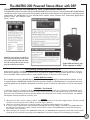
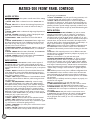
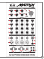
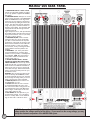
Inside This Instruction Manual Important Safety Instructions / Features........................................................................2 Product Features / Precautions......................................................................................3 Amplifier and Mixer Descriptions..................................................................................4 Set-up & Warranty Information.....................................................................................5-7 Contact Information......................................................................................................8 IMPORTANT SAFETY INFORMATION 1) Read these instructions. 2) Follow all instructions 3) Keep these instructions 4) Heed all warnings 5) Do not use the MATRIX-200 near water. Be extra cautious when moving the system during rain or while transporting the system over wet surfaces as water might splash on to the amplifier. To reduce the risk of fire or electric shock, do not expose the system to rain or moisture. 6) Clean only with dry cloth. 7) Do not block any ventilation openings. Use in accordance with manufacturer’s instructions. 8) Do not use near heat sources such as radiators, stoves or other devices that may produce heat. 9) Do not defeat the safety purpose of the polarization or grounding-type plug. A polarized plug has two blades with one wider than the other. A grounding-type plug has two blades and a third grounding prong. The wide blade or the third prong is provided for your safety. If the provided plug does not fit your outlet, consult an electrician for replacement of the obsolete outlet. 10) Protect the power cord from being walked on or pinched, particularly at the plug and at the point where it exits the MATRIX-200 amplifier. 11) Only use attachments / accessories recommended by B-52 Pro-Audio. 12)Use caution when transporting the system to avoid injury from tip-over. 13)Unplug the MATRIX-200 during lightning storms or when not in use. 14)Refer all servicing to qualified personnel. Servicing is required when the MATRIX-200 has been damaged in any way, such as the power-cord or plug is damaged, liquid has been spilled into the cabinets, the unit has been exposed to moisture or rain, does not operate normally, or has been dropped. 15) The MATRIX-200 is not intended for outdoor fixed installations or in high moisture areas. Moisture can damage the speakers and can cause corrosion of electrical contacts. Keep speakers out of extended or intense direct sunlight. The speaker surfaces may fade and be damaged by long-term exposure to intense ultra-violent light. 2 HEED ALL WARNINGS CAUTION RISK OF ELECTRIC SHOCK DO NOT OPEN WARNING: To reduce the risk or fire or electrical shock do not expose this equipment to rain or moisture. Caution: Connect the power cable only after you have made absolutely sure the local mains voltage matches the voltage specified on the device. If you connect to the wrong voltage, you may destroy the electronic components of the MATRIX-200 system. Stereo Power Amplifier features • Output stage with discrete devices, not integrated IC amps • Output power of 2 x 100w RMS with significant headroom for peaks • Comprehensive amplifier and speaker protection circuitry to guard against short circuits, DC offsets, over-heating, turn-on thumps, subsonic and supersonic frequencies. • Built-in stereo clip limiter • Equalization customized to enhance and optimize speaker system performance • Output for stereo headphones on rear panel • Very efficient cooling, utilizing a large heatsink and two direct flow fans • Power supply with low-noise torodial transformer and a dual voltage (115/230Vac) selector switch 5-Channel Mixer features • Four channels with both balanced XLR mic inputs and unbalanced 1/4” jack line level inputs n 15Vdc phantom power on balanced XLR inputs for condenser microphones n Independant PAN, TONE and EFFECT LEVEL controls on each channel • One stereo channel for variety of sources: n 1/4” TRS-style Stereo Phone Jack n 3.5mm Stereo Jack for MP3 / CD players n Dedicated mono 1/4” Jack INSTRUMENT input with frequency response contoured for acoustical instruments • Low distortion, low noise circuitry Loudspeakers • Dual 6.5” drivers optimized for D’Appolito (mirrored woofers) configuration • 1” exit phenolic tweeter on exponential horn ideally matches dual 6.5” speakers Complete system Dimensions: 20” (W) x 32“ (H) x 15” (D) Weight: 80 (lbs) • PLAYBACK input/output RCA connectors with LEVEL control • PATCH section to connect optional external processors, external effects and foot switch • 3-band MASTER EQ section • xlr output for external subwoofer. • Sub switch not only engages low frequency output but also removes deep bass from satellites thus increasing dynamic range and lowering overall system distortion Built-in DSP Effects • Eight built-in high quality DSP effects n Level control to mix processed signal with main signal n INPUT/MASTER switch to route effects to either Master section or to individual channels • Sophisticated mixer topology allows the combination of external effect devices to be used in combination with internal dsp Note: Specifications are subject to change without notice The MATRIX-200 Powered Stereo Mixer with DSP Congratulations on your purchase of this B-52 Professional MATRIX-200. The MATRIX-200 is the newest member of the popular B-52 MATRIX family of active systems. Compact and portable, the Matrix-200 can deliver powerful, clean and accurate sound, ideal for applications such as karaoke, music playback, or small stage soundreinforcement. The MATRIX-200 has a true 200-watt stereo amplifier, built-in 5-channel mixer, studio-quality digital effects, phantom power and numerous patch inputs / outputs. Caution: The system’s components are matched for the best possible sound quality and may only be operated in the specified configuration provided in this manual. Use of other two-way speakers may hinder the sound quality and can damage the power amplifier. Speaker cables and suitcase to carry all three components are included Hearing damage, prolonged exposure to excessive SPL B-52 Pro-Audio speakers, including the MATRIX-200, are capable of producing sound pressure levels (SPL) sufficient to cause permanent hearing damage to performers, production crews or people in the audience. Hearing protection devices such as ear-plugs are recommended. Caution should be taken to avoid extended exposures to spl levels in excess of 85 dB. Amplifier Module Precautions Do not attempt to service the MATRIX-200 by yourself. Refer all servicing to a B-52 Pro-Audio Authorized dealer. Service is required when the matrix-200 amplifier has been exposed to liquids or suffered damage. Do not operate the unit if liquid has spilled into the amplifier. Immediately remove the power cord from AC mains power if such an event should occur. WARNING – Shock Hazard To reduce the risk of fire or electrical shock, do not expose this unit to rain or moisture. Do not operate your MATRIX-200 near a pool or other standing water. Make sure all blades on the polarized power plug are fully inserted into the power source. Ensure the power cord is not stretched, pinched or otherwise abused. Ensure the power cord is routed to avoid foot traffic. Your MATRIX200 amplifier should be cleaned only with a dry cloth. 1) 2) 3) 4) Cautions When placed on slick, smooth or slippery surfaces, vibrating speakers may move from their original location. Precautions should be taken to insure the system does not fall off of a raised stage or platform. Please turn the volume down prior to turning the system on to prevent possible damage to the speakers. If you are using an optional active subwoofer with the MATRIX-200, be sure all cabling is connected to the MATRIX-200 from the subwoofer, the subwoofer’s volume control(s), and the volume control of the MATRIX-200 are turned all the way down, before either unit is powered on. After connecting your source(s) to the MATRIX-200, make sure your MATRIX-200 and signal sources have their volume controls turned all the way down before powering on the MATRIX-200 to avoid turn on thumps that could damage your speakers. 3 MATRIX-200 FRONT PANEL CONTROLS MASTER SECTION The Master Section gives the operator overall control of the settings that apply to all inputs. 1. MASTER - BASS: Adds or subtracts bass to the Matrix-200 output. 2. MASTER - MID: Adds or subtracts the mid-range frequencies produced by the Matrix-200. This control will add vocal clarity or instrument presence. 3. MASTER - TREBLE: Adds or subtracts the high range frequencies in the overall mix. 4. MASTER - PLAYBACK: Controls the volume of the playback input jacks, shown as No.23 on the diagram (right). 5. DIGITAL EFFECTS - LEVEL: Controls the mix level of the built in effects. 6. MASTER - DIGITAL EFFECTS: The Matrix-200 features eight versatile settings designed to suit a host of differing musical needs and tastes such as Large Hall, Large Room, Small Hall, Small Room, Echo, Slap Back, Chorus Reverb and Chorus. 7. DIGITAL EFFECTS SOURCE: MASTER/INPUT SWITCH: Controls routing internal DSP effects to either MASTER section, or to individual channels. 8. MASTER - POWER: When this led is illuminated, the matrix-200 is connected to ac mains voltage and powered on. 9. MASTER - VOLUME: Controls overall volume of the Matrix-200 except for the playback inputs (See Description 4). INPUT SECTION The Input section of the Matrix-200 controls various aspects of the external audio sources which can be plugged into the mixer, including microphones, guitars, keyboards and certain other devices equipped with either 1/4” jacks, 3.5mm stereo jacks, or microphone outputs 10. INPUT - EFFECTS: Controls level of each individual channel routed to digital effects section when Effects Master/Input switch is in Source position. These controls are not active when Effects Master/ Input switch is in Master position. 11. INPUT – TONE: Adjusts tonal balance of each individual channel. Turning tone counter-clockwise adds bass, while turning tone clockwise adds treble. 12. INPUT – PAN (PAN/BALANCE on Channel 5): Controls routing mono signals from Channels 1-4 to either Left or Right speakers. Place PAN in neutral position to keep source centered. Turning this control from center moves the image of the performer on this channel towards one side. Either fully clockwise or counter-clockwise will place this performer in either the right or left side alone. PAN/ BALANCE on Channel 5 balances stereo image on stereo sources connected to either STEREO LINE 1/4” jack (15) or stereo MP3/CD 3.5mm jack (16), or pans mono source connected to INSTRUMENT 1/4” jack (17). 13. INPUT – VOLUME: Controls volume of each individual channel. 14. INPUT – LINE: Unbalanced 1/4” jack inputs for channels 1-4. Will accept wide variety of music sources. Tip is connected to signal (+), while sleeve is connected to signal ground (—). 15. INPUT – STEREO LINE: 1/4” stereo jack to connect stereo sources with line level output(s). 16. INPUT – MP3/CD: 3.5mm stereo pin plugs (TRS style) connects so that your portable music source(s) can be used as an input to 4 play through your MATRIX-200. 17. INPUT – INSTRUMENT: 1/4” jack input for string instrument, such as acoustical guitar with passive pickup, or electrical guitar. 18. INPUT – MIC: Balanced XLR inputs to connect low-impedance microphones to channels 1-4. These inputs will accept virtually any microphones, both dynamic and condenser. All four XLR inputs are phantom powered to provide voltage required by condenser microphones. These inputs will also accept any mic-level balanced signals. PATCH SECTION 19. INSERT INPUT/OUTPUT LEFT and RIGHT: 1/4” jacks to connect external processing device, such as compressor or equalizer to Matrix-200. Each 1/4” jack has input and output; one jack for Left channel and one jack for Right channel. SLEEVE on 1/4” jack is connected to the ground. RING must be connected to the input of external device, and TIP must be connected to the output of external device. Please refer to the diagram labeled “Y-Cable Setup” on Page 7 of this manual for a graphic depiction of this. NOTE: Different processors may have a different configuration than the Matrix-200 on their connectors. Please review the manual information of the external processor before assuming it is the same as the Matrix-200. If the external processor uses a different connection standard, then you will likely need to buy adaptors to properly connect the two units together. Note: Do not insert Mono 1/4” jacks into insert jacks. 20. EFFECTS SEND/RETURN LEFT and RIGHT: 1/4” jacks to connect external effects processor. Each 1/4” jack has input and output; one jack for Left channel, and one jack for Right channel. SLEEVE on 1/4” jack is connected to the ground. RING must be connected to the input of external processor, and TIP must be connected to the output of external processor. Please refer to the diagram labeled “Y-Cable Setup” on Page 7 of this manual for a graphic depiction of this. NOTE: Different processors may have a different configuration than the Matrix-200 on their connectors. Please review the instruction manual information of the external processor before assuming it is the same as the Matrix-200. If the external processor uses a different connection standard, then you will likely need to buy adaptors to properly connect the two units together. Note: Do not insert Mono 1/4” jacks into insert jacks. 21. FOOTSWITCH EFFECTS/MUTE: This 1/4” jack is used to connect footswitch to remotely mute digital effects and master volume. 22. RECORD OUTPUTS: RCA jacks to connect stereo recording device to Matrix-200. This record output is unaffected by the Master volume control. 23. PLAYBACK INPUTS: RCA jacks used to connect stereo source to Matrix-200. This input bypasses all controls, including Master Volume (9) and Equalizer (1), (2), and (3), and is controlled only by playback level control (4). It is also not affected by Mute Footswitch (22). 5 MATRIX-200 REAR PANEL 1. LOUDSPEAKER OUTPUTS – RIGHT and LEFT: Connect to right and left speakers accordingly. Use only speakers supplied with Matrix200 System. 2. SUBWOOFER OUTPUT: XLR output to connect optional active subwoofer to the Matrix-200. While the Matrix-200 is a full range active system, the very low frequency performance can be enhanced by adding an external subwoofer. The subwoofer will both extend the range of the system, and add increased low frequency output ability. The subwoofer XLR output jack has both left and right channels combined, minus the higher frequencies sent to, and reproduced by the satellite speakers. The XLR output only has signal present when the “sub sw” (sub switch; item # 3) is in the on position. 3. SUBWOOFER ON/OFF: Used to activate subwoofer output (2), and to activate high pass filters on main channels. This improves performance of the system by causing a more ideal acoustical summation of the subwoofer and main speakers. It does so by limiting cone excursion, and by increasing the headroom available to both the speakers and amplifier. 4. HEADPHONES: 1/4” stereo jack used to connect headphones for monitoring when speaker use is not possible, or if headphones are preferable. NOTE: This jack is inactive if the speaker cables are inserted into the speaker output jacks (1). 5. VOLTAGE SELECTOR SWITCH: DO NOT CHANGE THIS SETTING WITH THE AC MAINS POWER ATTACHED! This switch is only used to modify the unit when it is transported to a different location with a different available AC mains source (such as moving a unit bought in the USA to Europe). Please check that this switch is in the appropriate position for your local electric source. WARNING: Using an improper setting on this switch can destroy the MATRIX-200, create an electrical hazard and void your warranty! Do not change this setting unless you must to match to the AC mains power available. 6. POWER ON/OFF: Press this switch to turn the Matrix-200 on or off. 7. AC INLET: Male IEC AC mains connector for standard detachable AC mains cords. This cord will also need to change if the unit is moved between regions with different AC mains voltages. It will require an AC mains switch setting change as well. 8. FUSE HOLDER: This fuse depends on your local AC Mains voltage. For 115V setting, this fuse is a 5amp T5AL. For the 230V setting, the fuse used is a T2.5AL as shown. 6 Caution: Connect the power cable only after you have absolutely made sure that the local mains voltage matches the voltage specified on the device. If you connect to the wrong voltage, you may destroy the electronic components of the MATRIX-200 system. MATRIX-200 INPUT PLATES Y-CABLE SET-UP FOR PATCH SECTION MONO/RING 1/4” 1/4” 1/4” Stereo Jack RING Tip MONO/TIP TIP Sleeve Ring A tip, ring, sleeve Y-cable used in the patched section of the Matrix-200 allows you to insert external devices and improve the performance of the system. This Y-cable is needed in the insert and effects sections. Please refer to the wiring plan above. Insert (Left and Right), refer to #19 on page 4: TIP: Input of the Matrix-200; connects to the output of the external device. RING: Output of the Matrix-200; connects to the input of the external device. Effects (Left and Right), refer to #20 on page 4: TIP: Input of the Matrix-200; connects the output of the external processor. RING: Output of the Matrix-200; connects to the input of the external processor. This input plate is located on the rear of the two satellite speakers. The input connector is for a 1/4” male connector. FOOTSWITCH: TIP: Controls effects. RING: Controls (mutes) outputs Limited Warranty Thank you for choosing a B-52 sound product. B-52 manufactures some of the world’s best sounding and most reliable professional speaker systems, amplifiers and components. E.T.I. Sound Systems, Inc., makers of B-52, takes great pride in thoroughly testing each B-52 product prior to shipment. B-52 CABINETS: E.T.I. Sound Systems, Inc. offers a lifetime warranty (effective on or after January 1, 2002) to the original purchaser that B-52’s cabinet construction will be free from defects in material and workmanship. A dated sales receipt will establish coverage under this warranty. This warranty does not cover service or parts to repair damage caused by neglect, abuse, normal wear and tear and cosmetic appearance to the cabinetry not directly attributed to defects in materials or workmanship. Also excluded from coverage are damages caused directly or indirectly due to any service, repair(s), or modifications of the cabinet which has not been authorized or approved by ETI Sound Systems, Inc. If this product is defective in materials or workmanship as warranted above, your sole remedy shall be repair or replacement as provided above. IMPORTANT: The included MATRIX-200 suitcase does not constitute a cabinet under this warranty. The suitcase is covered by a 90-DAY warranty against manufacturing defects. LOUDSPEAKER AND MID-RANGE COMPONENTS: E.T.I. Sound Systems, Inc. warrants the original purchaser that B-52 low and mid-frequency loudspeaker units will be free from defects in materials and workmanship for a period of (5) FIVE YEARS from the original purchase date (effective on or after January 1, 2002). A dated sales receipt will establish coverage under this warranty. This warranty will automatically terminate (5) years after the original retail sales date. This (5) five-year warranty does not cover service or parts to repair damage caused by accident, disaster, misuse, abuse, burnt voice-coils, over-powering, negligence, inadequate packing or shipping procedures and service, repair or modifications of the component which has not been authorized or approved by E.T.I.. This warranty is in lieu of all other expressed warranties. If this product is defective in materials or workmanship as warranted above, your sole remedy shall be repair or replacement as provided above. HIGH-FREQUENCY DEVICES: E.T.I. Sound Systems, Inc. offers a lifetime warranty (effective on or after January 1, 2002) to the original purchaser that B-52 high frequency (tweeters) devices will be free from defects in material and workmanship. A dated sales receipt will establish coverage under this warranty. This warranty does not warranty neglect or abuse. The warranty does not cover neglect or product abuse. The lifetime warranty on high-frequency devices does not cover service or parts to repair damage caused by accident, disaster, misuse, abuse, negligence, inadequate packing or shipping procedures or service, repair or modifications of the product which has not been authorized or approved by E.T.I. This warranty is in lieu of all other expressed warranties. If this product is defective in materials or workmanship as warranted above, your sole remedy shall be repair or replacement as provided above. AMPLIFIERS: E.T.I. Sound Systems, Inc. warrants the original purchaser that B-52 amplifiers will be free from defects in material and workmanship for a period of (2) two years from the original purchase date (effective on or after January 1, 2002). A dated sales receipt will establish coverage under this warranty. This warranty will automatically terminate (2) years after the original retail sales date. This (2) two-year warranty does not cover service or parts to repair damage caused Warranty valid ONLY to original purchaser with Proof of Purchase. by accident, disaster, misuse, abuse, over-powering, negligence, inadequate packing or shipping procedures and service, repair or modifications of the amplifier which has not been authorized or approved by E.T.I.. This warranty is in lieu of all other expressed warranties. If this product is defective in materials or workmanship as warranted above, your sole remedy shall be repair or replacement as provided above. RETURN PROCEDURES: In the event repair or part replacement becomes necessary, follow the procedure(s) outlined below. Defective products must be shipped, together with proof of purchase, freight pre-paid and insured to the Authorized B-52 Dealer from whom you purchased the product or directly to E.T.I. Sound Systems. If a product must be returned to E.T.I. Sound Systems for warranty replacement/repair, a Return Authorization Number must be obtained from our Customer Service Department prior to shipping the product. NEVER RETURN THE ENTIRE CABINET__JUST THE DEFECTIVE COMPONENT: Identify and remove the defective component. If you are uncertain which component is defective, or need directions for removing a component, please contact our Customer Service Department for assistance. Components which are a part of an original B-52 speaker box must be sent directly to E.T.I. Products must be shipped in the original packaging or its equivalent; in any case, the risk of loss or damage in transit is to be borne by the purchaser. The Return Authorization Number must appear in large print directly below the shipping address. Always include a brief description of the defect, along with your correct return address and telephone number. When calling to inquire about a returned product, always refer to the Return Authorization Number. If E.T.I. determines that the unit was defective in materials or workmanship at any time during the warranty period, E.T.I. has the option of repairing or replacing the product at no additional charge, except as set forth below. All replaced parts become a property of E.T.I. Products replaced or repaired under this warranty will be returned via ground-shipping-within the United States-freight prepaid. E.T.I. is not responsible for costs associated with expedited shipping, either to E.T.I. or the return of the product to the customer. INCIDENTAL OR CONSEQUENTIAL DAMAGE: In no event will E.T.I. be liable for any incidental or consequential damages arising out of the use or inability to use of any B-52 product, even if E.T.I. or a B-52 dealer has been advised of the possibility of such damages, or any other claim by any other party. Some states do not allow the exclusion or limitation of consequential damages, so the above limitation and exclusion may not apply to you. This warranty gives you specific legal rights and you may also have other rights which may vary from state to state. FOR YOUR PROTECTION: Please complete and mail the Purchase Information Card within (10) ten days of the date of purchase so that we may contact you directly in the event a safety notification issued in accordance with the 1972 Consumer Product Safety Act. In addition, we ask that you complete the brief questionnaire so me may analyze your answers and in this way, help us evaluate our customer needs. CUSTOMER SERVICE: Our dedicated staff is ready to help you with any B-52 warrant or product questions you may have. Please call 323-277-4100 (9:00AM to 4:00PM Pacific Standard Time). E.T.I. Sound Systems, INC. 3383 Gage Ave., Huntington Park, CA, 90255 7 B -52 PR OFESSIO N A L E.T.I. SOUND SYSTEMS, INC. 3383 Gage Avenue, Huntington Park, CA, 90255 Phone: 323-277-4100 Fax: 323-277-4108 National: 1-800-344-4ETI Internet: www.B-52PRO.com E-mail: [email protected] NOTE: This equipment has been tested and found to comply with the limits for a Class B digital device, pursuant to part 15 of the FCC Rules. These limits are designed to provide reasonable protection against harmful interference in a residential installation. This equipment generates, uses and can radiate radio frequency energy and, if not installed and used in accordance with the instructions, may cause harmful interference to radio communications. However, there is no guarantee that interference will not occur in a particular installation. If this equipment does cause harmful interference to radio or television reception, which can be determined by turning the equipment off and on, the user is encouraged to try to correct the interference by one or more of the following measures: — Reorient or relocate the receiving antenna. — Increase the separation between the equipment and receiver. — Connect the equipment into an outlet on a circuit different from that to which the receiver is connected. — Consult the dealer or an experienced radio/ TV technician for help. Changes or modifications not expressly approved by the party responsible for compliance could void the user’s authority to operate the equipment. This device complies with part 15 of the FCC Rules. Operation is subject to the following two conditions: (1) This device may not cause harmful interference, and (2) this device must accept any interference received, including interference that may cause undesired operation.