1
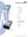
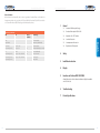
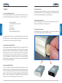
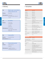
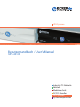
USV-Systeme Benutzerhandbuch / User’s Manual IUPS-401-B1 Industrie-PC-Netzteile Netzteile Medizintechnik DC/DC-Wandler USV-Systeme Systemkomponenten Benutzerhandbuch IUPS-401-B1 1 Allgemein 1.1 Lieferumfang und Lagerung 1.2 Systembeschreibung IUPS-401-B1 1.3 Automatische EIN / AUS-Funktion 1.4 Überlastschutz 1.5 Übertemperaturschutz 1.6 Austausch der Frontplatte 2 Sicherheit 3 Einbauanweisung 4 Bediendisplay IUPS-401-B1 mit Standard-Frontblende / with standard front panel 5 Schnittstelle und Software RUPS 2000OEM Eine ausführliche Beschreibung der Software-Installation in englischer Sprache befindet sich auf beiliegender CD. 6 Fehlerbehebung 7 Technische Daten IUPS-401-B1 mit gewechselter, schwarzer Frontblende / with exchanged black front panel 2 3 Benutzerhandbuch IUPS-401-B1 1. Allgemein 1.1 Lieferumfang und Lagerung Überprüfen Sie sofort nach Erhalt Ihrer IUPS ob Lieferschäden vorliegen. Eine beschädigte Verpackung kann ein Anzeichen hierfür sein. Im Lieferumfang enthalten sind: 1 USV-Gerät IUPS-401-B1 1 CD mit Software RUPS 2000OEM 1 Slotblech mit 5-poligem Steuerkabel 1 Netzkabel 1 Benutzerhandbuch 1 schwarze Frontplatte Soll die IUPS für einen längeren Zeitraum gelagert werden, so empfiehlt es sich, die Batterien der IUPS-401-B1 vorher mindestens 8 Stunden aufzuladen. Diese Aufladung muss bei Lagerung alle 6 Monate wiederholt werden. Die Lagerung sollte kühl und trocken erfolgen. Benutzerhandbuch IUPS-401-B1 1.4 Überlastschutz Der Laststrom wird von der IUPS überwacht. Bei Überlast während des Batterie betriebs schaltet die IUPS ab. Bei Überlastung im Netzbetrieb ist ein Dauerton zu hören, der bei Beseitigung der Überlast erlischt. 1.5 Übertemperaturschutz Die interne Temperaturüberwachung signalisiert eine auftretende Übertemperatur durch die rote LED und eine akustische Warnung. 1.6 Austausch der Frontplatte Die Standard-Frontplatte kann jederzeit getauscht werden. Dazu muss eine Münze vorsichtig in der seitlichen Vertiefung gedreht werden. Eine schwarze Frontplatte ist im Lieferumfang enthalten. 1.2 Systembeschreibung IUPS-401-B1 Die IUPS-401-B1 (Internal Uninterruptible Power Supply) ist eine integrierte USV (400 VA/240 W), gedacht zum Einbau in den 5 1/4“-Laufwerksschacht eines Computers. Bei Netzbetrieb werden durch die internen Filter störende und gefährliche Über spannungen, Transienten und Spannungsstöße wirkungsvoll gefiltert. Eine Zerstörung von wichtigen Daten und Hardwareschäden wird verhindert und verlängert so die Lebensdauer des Systems. Bei Netzunter-, Netzüberspannung oder Netzausfall übernimmt die IUPS-401-B1 die Versorgung des angeschlossenen Systems. Im sogenannten Back-up-Betrieb liefert der PWM-Inverter die notwendige Spannung. 1.3 Automatische EIN / AUS-Funktion Beim Anschluss der IUPS an die Netzversorgung prüft der interne Lastsensor automatisch, ob am Ausgang eine Last (Computer) angeschlossen ist. Ohne Last und ohne Netzeingangsspannung schaltet die IUPS innerhalb von ca. 20 Sek. automatisch ab. Bei Rückkehr der korrekten Netzspannung schaltet die IUPS automatisch wieder ein. Die nachgeschaltete Last wird mit der Netzspannung versorgt. Durch Drücken der Taste (>2 Sek.) kann die Last am Ausgang ein- und ausgeschaltet werden. 4 5 Benutzerhandbuch IUPS-401-B1 Benutzerhandbuch IUPS-401-B1 2. Sicherheit 3. Einbauanweisung Bitte beachten Sie die Einbauanweisung und nachfolgende Sicherheitshinweise. Durch den Einbau der IUPS in den Rechner an einer Stelle mit möglichst niedriger Temperatur erlangen Sie eine Optimierung der Batterielebensdauer. 1. Der Einbau und Anschluss der IUPS-401-B1 darf nur durch eine qualifizierte Elektrofachkraft erfolgen. Die einschlägigen Regeln der Elektrotechnik sind zu beachten. Die USV-Geräte dürfen nur mit der beiliegenden Netzanschlussleitung betrieben werden. 2. Die IUPS ist nur für den Einbau und Betrieb in einem Gehäuse zugelassen. Zu Beginn des Einbaus ist der Netzstecker zu ziehen und Spannungsfreiheit im System festzustellen. 3. Bei der Montage ist auf sichere Befestigung der IUPS-401-B1 zu achten. Zur Montage müssen ausschließlich die beigefügten Schrauben verwendet werden. Keinesfalls dürfen längere Schrauben verwendet werden. 1. Netzstecker abziehen 2. Slotblech mit 5-pol. Steuerkabeleinbauen 3. 5-pol. Steuerkabel an der IUPS einstecken 4. Netzkabel der IUPS und das IUPS-Spezialkabel einstecken 5. Netzkabel der IUPS mit dem Netzteil des Rechners verbinden 6. Netzstecker mit dem IUPS-Netzkabel verbinden 4. Der Austausch der Batterien darf nur durch eine qualifizierte Elektrofachkraft erfolgen. 5. Es ist darauf zu achten, dass die Summe der Ableitströme der IUPS-401-B1 und des angeschlossenen Verbrauchers 3,5 mA nicht überschreiten Vorsicht, Gefahr durch elektrischen Schlag! Auch nach Trennung von der Netzeingangsspannung werden Teile innerhalb der USV von der Batterie gespeist und führen gefährliche Spannungen. Bei Arbeiten am Gerät sind die internen Batteriestecker abzuziehen. 6 7 Benutzerhandbuch IUPS-401-B1 4. Bediendisplay Benutzerhandbuch IUPS-401-B1 5. Schnittstelle und Software RUPS 2000OEM TEST TEST TEST „Netzbetrieb“-LED: Die grüne LED leuchtet, wenn die Netzspannung anliegt. Die grüne LED blinkt bei Batterieladung. Als Meldesignale stehen zur Verfügung: „Netzausfall“: Transistorstrecke (Optokoppler) zwischen Pin 2 und Pin 4 (Common) wird leitend TEST „Back-up-Betrieb“-LED: Die rote LED blinkt, sobald die Netzspannung abgefallen ist und die IUPS die Stromversorgung übernommen hat. Der akustische Alarm ertönt alle 3 Sekunden. TEST „Batterie leer“-LED: Die rote LED blinkt (schnell), wenn die Batterie schwach ist. TEST Die Schnittstelle an der Rückseite der IUPS-401-B1 kann über ein Spezialkabel (im Lieferumfang des Softwarepakets) mit der seriellen Schnittstelle des Computers verbunden werden. Durch die Installation der Software (optional), 1. kann bei Netzausfall eine Warnmeldung am Monitor angezeigt werden 2. können offene Dateien automatisch gesichert werden 3. kann nach dem Shut down des Rechners die USV abgeschalten werden. TEST „Batterie leer“: Transistorstrecke (Optokoppler) zwischen Pin 5 und Pin 4 (Common) wird leitend „Abschaltung IUPS“: Eingang für RS-232 high level (5-12V) für > 1,5 msec. schaltet die IUPS bis zur Wiederkehr der Netzspannung ab. Anschluss an Pin 6 und Pin 7 (Common) Anmerkung: Maximale Belastung der Optokoppler: +35 V DC / 150 mA (nicht-induktiv) Die Pins 4 und 7 können mit Masse (Ground) verbunden werden, müssen jedoch gegenüber den Pins 2, 5 und 6 mit negativerem Potential beschalten sein. „Störungs“-LED: Tritt auf bei Überlast, Übertemperatur und internem Fehler Überlast: Die rote LED leuchtet bei Überlast. Der akustische Alarm ertönt permanent und die USV schaltet die Last ab. Sobald die Überlast beseitigt ist, wird die Ausgangsspannung wieder zugeschaltet. Der Dauerton erlischt nach ca. 30 Sekunden. Übertemperatur / Interner Fehler: Die rote LED blinkt und der Warnton ist kontinuierlich alle 2 Sekunden zu hören. 8 9 Benutzerhandbuch IUPS-401-B1 6. Fehlerbehebung Fehler: Obwohl der Computer angeschlossen und eingeschaltet ist, zeigt die IUPS keine Funktion oder Alarm Möglicher Grund: Fehler bei der Installation Behebungsvorschlag: 1. Netzstecker ziehen 2. Überprüfen der gesamten Installation gemäß Anleitung Fehler: Keine der LED‘s leuchtet Möglicher Grund: 1. Netzspannung fehlt 2. USV ist ausgeschaltet 3. Sicherung defekt 4. USV keine Funktion Behebungsvorschlag: 1. Netzspannung überprüfen 2. USV am Taster (Frontplatte) einschalten 3. Servicepersonal anrufen Fehler: Dauerton, LED rot Möglicher Grund: Überlast am Ausgang der USV Behebungsvorschlag: Last reduzieren Fehler: PC stürzt nach Netzausfall ab Möglicher Grund: 1. Batteriekapazität zu gering 2. Batterie defekt Behebungsvorschlag: 1. IUPS mindestens 8 Stunden laden 2. Batterie durch Servicepersonal tauschen lassen Benutzerhandbuch IUPS-401-B1 7. Technische Daten Technische Daten Leistung 400 VA / 240 W Eingangsspannung 230 V AC ±15 % Eingangsfrequenz 50 / 60 Hz ±5 % Ausgangsspannung 230 V AC ±15 % Ausgangsfrequenz 50 / 60 Hz ±1 % Ladezeit Ca. 8 Std. (90 % Ladung) USV-Klassifizierung/Kurvenform VFD / Rechteck Schutzfunktionen Überlastschutz: USV-Betrieb: 100…120 %, Alarm / 120…190 %, Abschaltung Netzbetrieb: Sicherung Übertemperaturschutz: Abschaltung Umschaltzeit <6 ms Überbrückungszeit 100 W / 166 VA Last ca. 5 Minuten 180 W / 300 VA Last ca. 2…3 Minuten Schnittstelle Open Kollektor für USV-Management-Software Sicherheit / EMV EN62040-1-1 / CE / EN62040-2 Temperatur Betrieb: 0…+40 °C / Lagerung: 0…+40 °C Luftfeuchtigkeit Betrieb: 10…85 % RH, nicht kondensierend Lagerung: 10…90 % RH, nicht kondensierend Abmessungen 146 x 253 x 42 mm ±0,5 mm Gewicht (netto) 2,75 kg Produktspezifische Daten Umschaltschwelle Netz- / USV-Betrieb Umschaltschwelle in den USV-Betrieb bei Überspannung am Eingang Batterietyp Geräuschentwicklung Lastsensor Taste USV-Management-Software 190 V AC ±5 % 248 V AC ±5 % 2 x 6 V / 3 Ah Blei-Gel-Akku wartungsfrei <35 dbA Abschaltung bei <20 Watt Alarmton ausschalten: ca. 1 Sek. drücken USV ausschalten: ca. 4 Sek. drücken USV einschalten: (Kaltstart, ohne Netz), ca. 2 Sek. RUPS 2000OEM und 9-poliges Schnittstellenkabel im Lieferumfang enthalten Novell Netware, Windows® 2000 / 2003 / XP / Vista / 7 / 8, LINUX, weitere auf Anfrage Die Lebensdauer der Akkus beträgt bei +20 °C ca. 4…5 Jahre und halbiert sich um je 10 °C Temperaturerhöhung nach EUROBAT. Bei Einlagerung soll die USV spätestens nach 6 Monaten nachgeladen werden. 10 11 Benutzerhandbuch IUPS-401-B1 User’s Manual IUPS-401-B1 Reboot-Funktion Kehrt während eines Netzausfalls und der schon eingeleiteten Shutdown-Phase von Windows® die Netzspannung wieder zurück, so schaltet die USV (nach Ablauf der Shutdown-Zeit) den PC aus und nach ca. 30 Sekunden wieder ein (BIOS-Einstellungen des Mainboards beachten) Statusanzeige und Alarm LED Alarm Alarmton abschaltbar grün – Statusanzeige USV-Normalbetrieb General 1.1 Contents of Delivery and Storage 1.2 Functional Description IUPS-401-B1 1.3 Automatic ON / OFF Function 1.4 Overload Protection 1.5 Overtemperature Protection Replacement of front panel grün blinkend – Batterieladung (Netzbetrieb) rot blinkend 2 Beep alle 3 Sek. ja USV-Batteriebetrieb 1.6 rot blinkend (schnell) 4 Beep pro Sek. nein USV-Batteriebetrieb (Batt. schwach) 2 Safety 3 Installation Instruction 4 Display rot Dauerton nein Überlast (Netzbetrieb) rot blinkend (schnell) 8 Beep pro 2 Sek., 2 Sek. Ruhe nein USV-interner Fehler rot blinkend (schnell) 8 Beep pro 2 Sek., 2 Sek. Ruhe ja Übertemperatur rot blinkend (schnell) – Batterie defekt 5 12 English 1 Interface and Software RUPS 2000OEM A detailed description of the software installation in English is available on the CD enclosed. 6 Troubleshooting 7 Product Specifications 13 User’s Manual IUPS-401-B1 1. General 1 UPS unit IUPS-401-B1 1 Slot bracket with 5-pole control cable 1 Mains cable 1 User’s Manual 1 Black front panel 1 CD with software RUPS 2000OEM 1.4 Overload Protection Load current is monitored by the IUPS. In case of an overload during battery mode the IUPS switches off. In case of an overload during mains mode a permanent sound is generated, which will stop when the overload is eliminated. 1.5 Overtemperature Protection When an overtemperature is detected by the internal temperature control, this is indicated by the red LED and an acoustic alarm sound. 1.6 Replacement of front panel The standard front panel can easily be exchanged. To do so, turn a coin carefully in the recess at the side. A black front panel is part of the delivery. English English 1.1 Contents of Delivery and Storage Please check immediately upon reception whether the delivery is damaged in any way, for which packing damage may be an indication. The contents of delivery are: User’s Manual IUPS-401-B1 For storing the IUPS for some time it is recommendable to charge the batteries of the IUPS-401-B1 before for at least 8 hours. During storage the batteries must be charged every 6 months. The storage location should be cool and dry. 1.2 Functional Description IUPS-401-B1 The Internal Uninterruptible Power Supply IUPS-401-B1 is an integrated UPS unit (400 VA / 240 W) and designed for mounting into a 5 1/4“ drive slot of a computer. Interfering and dangerous overvoltage, transients and voltage surges are effectively filtered during mains mode by means of internal filters. Destruction of important data and hardware damage is thus prevented, which extends the service life of the system. In case of undervoltage or overvoltage of mains power or mains power failure the IUPS-401-B1 takes on the supply of the connected system. In back-up-mode the PWM inverter pro-vides the required voltage. 1.3 Automatic ON / OFF Function As soon as the IUPS is connected to mains supply the internal load sensor automatically checks whether a load (computer) is connected at the output. When no load and no mains input voltage are detected, the IUPS switches off automatically within app. 20 seconds. As soon as the correct mains voltage returns the IUPS automatically switches on again. The downstream load is supplied with mains voltage. By pressing the button (>2 sec) the load at the output can be switched on or off. 14 15 User’s Manual IUPS-401-B1 2. Safety 3. Installation Instruction Please observe the installation instruction and the following safety warnings. To optimize the service life of the battery install the IUPS into the computer at a location with preferably low temperature.. 1. Installation and connection of the IUPS-401-B1 must only be carried out by a qualified electrical technician. The relevant rules of electrical engineering must be observed. For powering the UPS units only the included power cord must be used. 2. The IUPS is only approved for installation and operation in a chassis.Before the installation disconnect mains and make sure that the system is voltage-free. English English User’s Manual IUPS-401-B1 3. During the installation make sure the IUPS-401-B1 is safely mounted. Only use the included screws for mounting the unit. Make absolutely sure that no screws that are longer than the included ones are used. 1. Disconnect mains 2. Install slot bracket with 5-pole control cable 3. Connect 5-pole control cable at the IUPS 4. Connect mains cable of the IUPS and the special IUPS cable 5. Connect the IUPS mains cable with the power supply of the computer 6. Connect mains plug with the IUPS mains cable 4. The batteries must only be exchanged by a qualified electrical technician. 5. Make sure that the combined leakage current of the IUPS-401-B1 and the connected consumer load does not exceed 3.5 mA. Warning, danger of electric shock! Even when mains is disconnected components within the UPS are supplied by the battery and contain dangerous voltages. For any work at the unit disconnect the internal battery connectors. 16 17 User’s Manual IUPS-401-B1 4. Display 5. Interface and Software RUPS 2000OEM TEST TEST TEST “Mains mode“ LED: The green LED is on when mains voltage is supplied. The green LED flashes during battery charge. TEST “Back-up mode“ LED: Combined with an acoustic alarm sound every 3 seconds the red LED flashes as soon as the IUPS has taken over power supply in case of mains power failure. TEST “Battery low“ LED: The red LED flashes (quickly) when the battery is low. TEST TEST “Failure“ LED: This failure indication is engaged in case of overload, overtemperature or an internal failure. The interface at the back of the IUPS-401-B1 can be connected to the serial interface of the computer via a special cable (included into the delivery of the software package). When the software (optional) is installed, 1.a warning message can be displayed at the computer monitor in case of mains power failure 2. open files can be stored automatically 3. the UPS can be switched off after the computer was shut down. The following status signals are available: “Mains power failure“: Transistor line (optocoupler) between Pin 2 and Pin 4 (Common) becomes conductive “Battery low“: Transistor line (optocoupler) between Pin 5 and Pin 4 (Common) becomes conductive “IUPS switch-off“: Input for RS-232 high level (5-12V) for >1.5 msec switches the IUPS off until mains voltage returns. Connection at Pin 6 and Pin 7 (Common) English English User’s Manual IUPS-401-B1 Note: Maximal load of optocouplers: +35 V DC / 150 mA (not inductive) Pins 4 and 7 can be connected to Ground, however, they must be wired with a more negative potential as compared to Pins 2, 5 and 6. Overload: In case of an overload the red LED turns permanently red combined with a permanent alarm sound, and the UPS switches the load off. As soon as the overload is gone, the output voltage is switched on again. The permanent sound stops after approximately. 30 seconds. Overtemperature / Internal failure: The red LED flashes combined with a warning sound continuously every 2 seconds. 18 19 User’s Manual IUPS-401-B1 6. Troubleshooting 7. Product Specifications Failure: Although the computer is connected and switched on, the IUPS shows neither function nor alarm Possible cause: Wrong installation Possible countermeasure: 1. Disconnect mains 2. Check the whole installation according to the instruction Failure: None of the LEDs is on Possible cause: 1. No mains voltage 2. UPS is switched off 3. Fuse is defect 4. No UPS function Possible countermeasure: 1. Check mains voltage 2. Switch on UPS at the (front panel) button 3. Call service staff Failure:Permanent sound, LED red Possible cause:Overload at the UPS output Possible countermeasure:Reduce load Failure:PC system crash after mains power failure Possible cause:1. Battery capacity too low 2. Battery defect Possible countermeasure: 1. Charge IUPS for at least 8 hours 2. Have battery replaced by service staff Technical data Output power Input voltage Input frequency Output voltage Output frequency Charging time UPS classification / Wave form Protection Transfer time Back up time Interface Safety / EMC Temperature Humidity Dimensions (W x D x H) Weight (net) Product-specific data Transfer limit in mains / UPS mode Transfer limit into UPS mode in case of overvoltage at the input Battery Noise development Load sensor Button UPS Management Software 400 VA / 240 W 230 V AC ±15 % 50 / 60 Hz ±5 % 230 V AC ±15 % 50 / 60 Hz ±1 % App. 8 h (90 % load) VDF / Rectangular Overload protection.: UPS mode: 100…120 %, Alarm / 120…190 %, Switch off Mains mode: Fuse Overtemperature protection: Switch off <6 ms 100 W / 166 VA load app. 5 min 180 W / 300 VA load app. 2…3 min Open collector for UPS management software EN62040-1-1 / CE / EN62040-2 Operating: 0…+40 °C / Storage: 0…+40 °C Operating: 10…85 % RH, non-condensing Storage: 10…90 % RH, non-condensing 146 x 253 x 42 mm ±0.5 mm 2.75 kg English English User’s Manual IUPS-401-B1 190 V AC ±5 % 248 V AC ±5 % 2 x 6 V / 3 Ah maintenance-free lead-gel batteries (VRLA) <35 dbA Switch off at <20 Watt To switch off alarm sound press for app 1 sec. To switch off UPS press for app 4 sec. To switch on UPS (cold start, without mains supply) press for app 2 sec. RUPS 2000OEM and 9-pole interface cable included Novell Netware, Windows® 2000 / 2003 / XP / Vista / 7 / 8, LINUX, others on request The service life of the batteries is app. 4…5 years at +20 °C and will decrease by half with each temperature increase of 10 °C according to EUROBAT. During storage the UPS has to be charged every 6 months.. 20 21 User’s Manual IUPS-401-B1 Reboot function If mains voltage returns after a power failure while Windows® is already shutting down, the UPS switches the PC off (after the shut-down period) and switches it on again after approximately 30 seconds (observe BIOS settings of mainboard). User’s Manual IUPS-401-B1 Notizen / Notes Status display and Alarm 22 Alarmsound disengageable Status display green – Normal UPS mode green flashing – Battery charge (mains mode) red flashing 2 beeps every 3 sec. yes UPS battery mode red flashing (quickly) 4 beeps per sec. no UPS battery mode (Battery low) red permanent sound no Overload (mains mode) red flashing (quickly) 8 beeps per 2 sec., 2 sec. stillness no Internal UPS failure red flashing (quickly) 8 beeps per 2 sec., 2 sec. stillness yes Overtemperature red flashing (quickly) – English English LED Alarm Battery defect 23 Industrial PC PSUs Power supplies Medical applications DC/DC converters UPS systems System components Irrtümer und technische Änderungen vorbehalten. Windows® ist ein eingetragenes Warenzeichen der Firma Microsoft Corp. Subject to errors and technical modifications. Windows® is a registered trademark of Microsoft Corporation. Stand/Issued: 06.06.2013 Bicker Elektronik GmbH Ludwig-Auer-Straße 23 86609 Donauwörth · Germany Tel. +49 (0)906 70595-0 Fax +49 (0)906 70595-55 E-Mail: [email protected] www.bicker.de