Download DataCard SP75 Plus Install guide
Transcript
SP75 Printer Guide 559455-001 Rev. A March 2005 Information resources for the SP75 Printer SP75 Printer Guide The Printer Guide (this document) contains operating information for the printer. SP75 Quick Install Guide The Quick Install Guide, packed at the top of the printer carton, shows you the steps to install the printer. For detailed installation information, see e-Guide/SP Series/SP_Info_Central.chm on the driver CD-ROM. Message Help If you see a message, click Help on the message box. Really! Help topics are short and to the point. SP Series Info For in-depth information about using the printer, install SP Info Central on a Windows PC, then click the icon on the desktop. (Insert the Smart Central and Driver CD-ROM and choose User Information to install SP Info Central.) e-Guide FAQs Service and Support FAQs at www.datacard.com provide answers to questions about the printer. Dealer For help with questions not addressed by other SP Series printer information, contact your dealer. Customer Care Contact the Datacard Customer Care Center at 1.800.328.3996 (U.S. & Canada) or 1.952.988.2316 (worldwide). Contents Laminator supply materials . . . . . . . .26 Cleaning supplies . . . . . . . . . . . . . . . .28 About the printer . . . . . . . . . . . . . . . . . . . . . 1 Printer Installation . . . . . . . . . . . . . . . . . . .29 Loading cards . . . . . . . . . . . . . . . . . . . . . . . 5 Printer LCD settings . . . . . . . . . . . . . . . . .30 LCD menu system . . . . . . . . . . . . . . .31 Loading print ribbon . . . . . . . . . . . . . . . . . . 7 Loading laminator supply material . . . . . . . 9 Status light . . . . . . . . . . . . . . . . . . . . . . . . 11 Check the PC connection . . . . . . . . . . . . . 13 Power on the printer . . . . . . . . . . . . . . . . . 14 The LCD panel . . . . . . . . . . . . . . . . . . . . . 15 Opening Properties or Printing Preferences 17 Open the Printer Toolbox . . . . . . . . . . . . . 19 Cleaning the printer . . . . . . . . . . . . . . . . . 21 Getting the most out of your printer . . . . . 23 Printer supplies . . . . . . . . . . . . . . . . . . . . 25 Color print ribbon . . . . . . . . . . . . . . . . 25 Monochrome and Topcoat ribbon . . . 25 Monochrome print ribbon . . . . . . . . . . 26 539409-001 Rev. A View status settings . . . . . . . . . . . . . . . . .32 View the Serial Number . . . . . . . . . . .32 View the Firmware Revision . . . . . . . .33 View Card Counts . . . . . . . . . . . . . . .33 View the Network Address Mode, IP Addresses, and MAC Address . .35 View the Ribbon Type . . . . . . . . . . . .37 View the Laminator Values . . . . . . . .37 Change settings . . . . . . . . . . . . . . . . . . . .39 Set LCD Backlighting . . . . . . . . . . . . .39 Set the Address Mode . . . . . . . . . . . .40 Set the IP Address, Subnet Mask, and Gateway Address . . . . . . . . .42 Set the Laminator Heater Temperature 44 Page iii Page iv Run diagnostics commands . . . . . . . . . . . 45 Run a printer cleaning card . . . . . . . . 45 Run a laminator cleaning card . . . . . . 47 Troubleshooting . . . . . . . . . . . . . . . . . . . . 49 Site requirements . . . . . . . . . . . . . . . . . . . 51 Operating environment . . . . . . . . . . . 51 Electrical requirements . . . . . . . . . . . 51 Physical requirements . . . . . . . . . . . . 51 Printer messages . . . . . . . . . . . . . . . . 52 DM-00760 Duplex Error . . . . . . . . . . . 53 DM-00762 Duplex Jam . . . . . . . . . . . 54 DM-00767 Duplex Jam . . . . . . . . . . . 55 DM-00768 Lower Duplex Jam . . . . . . 56 DM-00769 Lower Duplex Error . . . . . 57 DM-00770 Lower Duplex Jam . . . . . . 58 IS-01206 No Card Picked . . . . . . . . . 59 SY-01305 Data Error . . . . . . . . . . . . . 60 SY-01306 Data Error . . . . . . . . . . . . . 61 SY-01310 Flash Error . . . . . . . . . . . . 62 SY-01314 Flash Error . . . . . . . . . . . . 63 SY-01317 Memory Error . . . . . . . . . .64 SY-01325 Data Error . . . . . . . . . . . . .65 SY-01327 Data Error . . . . . . . . . . . . .67 SY-01331 Comm Error . . . . . . . . . . . .68 SY-01332 Hardware Error . . . . . . . . .69 MS-01401, MS-01402, MS-01403 Mag Stripe Data . . . . . . . . . . . . . .70 MS-01404, MS-01405, MS-01406 Mag Stripe Error . . . . . . . . . . . . .71 MS-01407, MS-01408, or MS-01409 Mag Stripe Error . . . . . . . . . . . . .72 MS-01410 Mag Stripe Error . . . . . . . .73 MS-01413 Mag Stripe Error . . . . . . . .74 MS-01417, MS-01418, MS-01419, MS-01420, MS-01421 Card Jam .75 MS-01424 Mag Stripe Error . . . . . . . .77 MS-01425 Mag Stripe Error . . . . . . . .79 MS-01426 EEPROM Error . . . . . . . . .80 MS-01427 Mag Stripe Error . . . . . . . .81 MS-01429 Mag Stripe Data . . . . . . . .82 MS-01430 Mag Stripe Error . . . . . . . . 83 MS-01431 EEPROM Error . . . . . . . . 84 MS-01435 No Mag Stripe . . . . . . . . . 85 OP-01604, OP-01654 L1 or L2 Heater Error . . . . . . . . . . . . . . . . 86 OP-01611, OP-01661 Roller Error . . 87 OP-01612, OP-01662 Card Jam . . . . 89 OP-01613, OP-01663 L1 or L2 Supply Error . . . . . . . . . . . . . . . . 91 OP-01614, OP-01664 Supply Break . 93 OP-01615, OP1665 L1 or L2 Supply Out . . . . . . . . . . . . . . . . . 95 OP-01616 Lam EEPROM Error . . . . . 97 OP-01619 Comm Error . . . . . . . . . . . 98 OP-01620 Wait for Temp . . . . . . . . . . 99 OP-01621, OP-01671 Supply Low . 100 OP-01622, OP-01672 Supply Error . 101 OP-01623 Lam Hardware Error . . . . 102 OP-01624, OP-01674 Card Jam . . . 103 OP-01651 No L2 Laminator . . . . . . . 105 PR-01703 Printhead Error . . . . . . . .106 PR-01705, PR-01706 Card Jam . . .107 PR-01710 EEPROM Error . . . . . . . .109 PR-01715 Cover Open . . . . . . . . . . .110 PR-01718 Printhead Temp . . . . . . .111 PR-01719 Printhead Error . . . . . . . .112 PR-01720 Ribbon Error . . . . . . . . . .113 PR-01721 EEPROM Error . . . . . . . .114 PR-01723 Hardware Error . . . . . . . .115 PR-01724 Ribbon Break . . . . . . . . .117 PR-01726 Ribbon Out . . . . . . . . . . .119 PR-01730 Printhead Error . . . . . . . .120 PR-01737 Ribbon Low . . . . . . . . . . .121 PR-01738 Ribbon Error . . . . . . . . . .122 SC-01804 No Smart Card . . . . . . . .123 Legal Notices (FCC) . . . . . . . . . . . . . . . .130 Liability statement . . . . . . . . . . . . . .130 Regulatory compliance . . . . . . . . . . .130 Trademark acknowledgments . . . . .130 Proprietary Notice . . . . . . . . . . . . . .130 Page v Page 1 About the printer This guide applies to the SP75 printer. The outside of the printer Printer Cover. Latch: Lift the latch to open the printer cover. Locks: Optional locks secure supplies. Input Hopper: Open the cover to load blank cards. LCD Panel: Shows the printer status and any messages. Use it to change network settings. Ready Key: Push to pause or resume the printer. The Status Light helps you understand printer operation. See "Status light" on page 11 for details. Card out slot: Cards removed from the print area (using the manual advance knob) exit here. Laminator Advance Knob: Moves cards in the laminator area. Output Hopper: Remove completed cards. Laminators: All SP75 printers have an L1 laminator. Some also have an L2 laminator. They apply topcoat or patch material to cards. L2 L1 On the left and back sides of the printer: Printer Guide Holder: Attach the holder and place the guide in it. Choose any convenient location. Ethernet Data Port:. Use only one data port. USB Data Port: Use only one data port. Manual Advance Knob: Use to move a card in the printer or to turn rollers. Cable Guide: Place the data cable in the guide. Back Door. Open to see both duplex units and the reject bin. Locks: Optional lock secures cards and supplies in the printer. See "Features and options" on page 3. Optional Smart Card USB Port: See "Features and options" on page 3. Optional Smart Card Serial Port: See "Features and options" on page 3. Power Switch: Press the switch to power on the printer. Power Receptacle: Plug in the power cord. Security Lock Receptacle: Connect the optional security lock to the opening. Page 2 
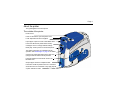
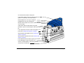
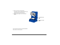
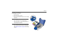
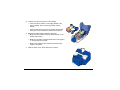
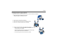
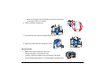
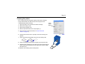
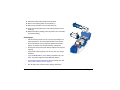
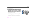
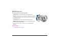
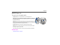
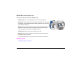
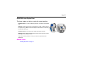
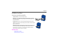
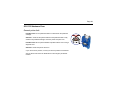
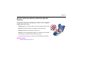
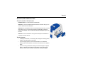
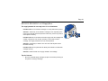
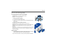
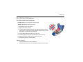
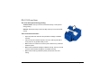
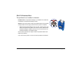
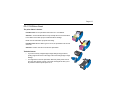
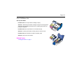
Page 3 The inside of the printer Cover Arm: Holds the cover and printhead cartridge in place. Printhead Cartridge: Applies the image to the card. Print Ribbon Cartridge, shown with color print ribbon. Printer Label: Includes the serial number and model information (located on the left side of the printer and not visible in this drawing). Cleaning Roller (not visible in this drawing): Removes dust and debris from cards. Features and options Features and options are identified on the printer label. • • • SP75 printers print in full-color (C) and have duplex or two-sided (2) printing. SP75 printers have both USB and Ethernet data ports. Use only one of these ports to connect your printer to the PC or a network. A magnetic stripe module can be a three-track (IAT) or single-track (NTT) module. • Printers can have a 100-card (H1) or 200-card (H2) input hopper. • Printers can have a high-capacity output hopper (no code on label). • The printer can have locks (K1 or K2) on the input hopper, back door, and top cover. (The top cover lock also secures the laminator cartridges.) • All SP75 printers have an L1 laminator. Some also have a second, L2, laminator. • An optional smart card module can have: — Combination smart card reader (SC346) with contact and contactless readers. Visible inside the printer, includes USB port. — Contactless iCLASS™ reader (SC205). Includes USB port. — Contact station (SC400): Visible inside the printer, includes a serial port. Page 4 Page 5 Loading cards 1 Open the input hopper cover. 2 Remove cards from the original package. Tips: Handling cards • Cards can stick together: Slide or fan cards to separate the edges. • Do not touch the surface of cards before printing them. (Oils on hands will reduce printing quality.) • Handle cards by the edges or wear gloves. • Orient all cards the same way. 3 Place the cards in the input hopper. The diagram shows the typical locations for the magnetic stripe and smart card chip. 4 Push the input hopper cover closed until it latches. Magnetic stripe Smart card chip See SP Series Info Central for current information about cards to use in the printer. Page 6 Page 7 Loading print ribbon 1 Open the printer. 2 Remove the ribbon cartridge. 3 Remove both used ribbon spools from the cartridge (if present). Tips: Handling print ribbon • Keep unused ribbon in the original package. • Don’t place ribbon on a dusty or dirty surface–dirt could damage the printhead. 4 Run a cleaning card and replace the cleaning sleeve at the same time that you load a new print ribbon. See "Cleaning the printer" on page 21 for the steps to follow. 5 Load the new roll of print ribbon on the cartridge. — Put the full spool of ribbon on the supply spindle of the ribbon cartridge. Push until the spool clicks onto the spindle. — Put the empty take-up spool on the spindle with the solid black gear. Push until the spool clicks onto the spindle. 6 Replace the loaded ribbon cartridge in the printer. — Make sure both spindles rest in the black supports on the left side of the printer. — Make sure the ribbon cartridge handle rests in the supports on the right side of the printer. — Make sure to install the full, new spool toward the input hopper of the printer. 7 Close the printer cover. Press down firmly to latch it. Page 8 Page 9 Loading laminator supply material If your printer has locks, unlock and lift the top cover to release the laminator cartridge(s). 1 Remove the laminator cartridge from the printer. Change the supply in one laminator at a time. 2 Open the gate on the laminator cartridge (1). 3 Remove both used spools (2) from the cartridge (if present). 4 Remove the new supply material from the packaging. 2 2 1 5 Load the new roll of laminator supply material in the cartridge. — Put the full spool on the supply spindle of the cartridge (A). Push until the spool clicks onto the spindle. — Put the empty take-up spool on the spindle with the solid black gear (B). Push until the spool clicks onto the spindle. — Turn the take-up spool to remove slack from the material. A B — Make sure the supply material is between the guides on both the takeup and supply sides of the cartridge. 6 Close the laminator cartridge gate. 7 Pinch both sides of the gate and cartridge together to close. 8 Replace the loaded laminator cartridge in the printer. Tips for Success • Make sure the laminate follows the path shown. • Change the supply in one laminator at a time. • Load the L1 laminator cartridge to the correct location in the printer. • Do not load material upside down, or it will be applied to the heated roller. Page 10 Page 11 Status light The front of the printer has a light on the LCD panel that provides information about the current state of the printer. At startup, the status light displays steady amber for several seconds, a red-amber-green sequence, and then blinking green for several seconds. When the printer is ready to print, the status light is steady green. Status Light Description Meaning Red-Amber-Green The printer is starting. The light displays colors while the printer initializes. Steady Green The printer is ready and waiting to print cards. Blinking Green The printer is busy, such as when printing cards or initializing. Status Light Description Meaning Steady Amber The printer is paused (without an error) or is initializing. Blinking Amber The printer has an error. Check the following: • See the PC or LCD panel for a message. • If you used the Power-on/Ready sequence to print a test card, check the printer for problems. • If you changed the printer name, power the PC off and on. Steady Red The printer has a condition that requires service or the printer did not power-on correctly. To attempt to correct the condition, power the printer off and on before calling for service. Off The printer power is off. Page 12 Page 13 Check the PC connection The printer and PC are connected when the printer is set up. Before you begin processing cards, make sure the connection is complete. The printer uses one data cable. It can be connected in one of the following ways: • A USB data cable can be connected to a USB port on the PC and to the USB data port on the printer (shown). • An Ethernet data cable can be connected to the network and to Ethernet data port on the printer. The PC must also be connected to the same network. • The printer can be connected to a network using a print server. The PC must also be connected to the same network. • As a shared printer, where the printer is connected to another PC on the network and the user’s PC is connected to the network. • See SP Info Central for more information about connecting the printer. PC Power on the printer 1 With the power off (press “O” on the power switch), connect the power cord to the printer power receptacle. 2 Power on the printer (press the “|” symbol on the power switch). 3 The printer powers on and the Status Light is amber. After a moment, the LCD panel shows the printer name (such as SP75) and firmware version. 4 When the printer is ready to print cards, the LCD panel shows “Printer Ready” and the data format. The Status Light displays steady green. Tips for printer power • Wait while the printer initializes. • Follow the guidelines for your organization about when to power the printer on and off. Page 14 Page 15 The LCD panel The SP75 Card Printer includes an LCD panel. The LCD panel has a 2-line display, four keys, and the Status light. This section describes what you need to know when printing cards. See "Printer LCD settings" on page 30 for detailed information about viewing and changing settings. The LCD panel provides the following: • Current State (line 1): Shows whether the printer is ready to print, is busy, or is paused. — Press the Ready (undo pause). key to pause or resume the printer • Data format (line 2). • Printer messages: The display shows the message number and a short description of the problem. — Fix the problem and then press the Ready key to clear the message. Repeat if another message is displayed. — See "Printer messages" on page 52 for details about messages. • Status: Information about the printer, including printer card counts and network settings. To view status details: — Press the Enter key to move to the Main Menu. — Press the Enter key again to enter the Status Menu. — Press the Up Arrow or Down Arrow scroll through the Status Menu choices. key to — Press the Enter key to view the data. — Press the Enter key again to return to the menu. — Scroll to “Exit” and press the Enter key to leave a choice. Repeat as needed to leave the menus. See "Printer LCD settings" on page 30 for details about viewing and changing settings. Page 16 Page 17 Opening Properties or Printing Preferences Begin with the printer connected to the PC and powered on so values are saved correctly. 1 Choose Start from the Windows task bar. 2 Choose Settings and then Printers (and Faxes). The Printers (and Faxes) window opens. 3 Click once on the Smart Driver printer icon to select it. — The driver must be installed for the printer icon to be present. — Smart Driver is the default name of the printer. The name of your printer might be different. 4 From the menu bar, choose File and then one of the following: — For Windows Me or 98, choose Properties. — For Windows 2000 or XP, choose Printing Preferences, and then click the Advanced button. — For Windows NT, choose Default Document Properties and then click the Advanced button. It might take a few moments for the dialog box to appear. Properties Dialog Box for Windows 98 and Windows Me 5 The dialog box opens. 6 View settings or change settings. — Make sure that driver settings match printer features and supplies used. — The Print Ribbon Type setting is read from the printer and cannot be changed (for most connection types). — If you change the card design, review and update all settings for the new card design. — Use the default settings of “Spool printing so program finishes printing faster.” and “Enable bi-directional support.” — To open the Printer Toolbox, choose “Open Printer Toolbox.” 7 Choose OK to save and close or choose Cancel to close without saving changes. See SP Series Info Central for detailed setup information, including information about settings for card features. Printing Preferences dialog box for Windows 2000 and Windows XP Page 18 Page 19 Open the Printer Toolbox The Printer Toolbox icon is located in the lower right corner of the Windows desktop. The icon shows the status of communication between the printer and PC. See SP Series Info Central for details about the icon. By default, the Printer Toolbox dialog box is displayed. If it is not, do one of the following to display it: — Double-click the icon. — Open the Properties or Printing Preferences dialog, and use the Printer Toolbox choices. Use the Printer Toolbox to: • Run a printer or laminator cleaning card. • Change color settings. • Print a sample card or magnetic stripe test card. • View the status of communication between the printer and PC. • Suspend communication when not printing a card. • Change edge to edge settings. • Use Advanced Setup to change printing intensity and laminator settings. The Printer Toolbox displays: • The current state of communication between the driver and printer. • Message text, if there are any messages. • The current port mode, which can be USB, Shared Mode, or Directly Networked. • The printer type. • The driver and printer firmware version numbers. Communication automatically resumes when you print a card, or when you open the Properties or Printing Preferences dialog box. Buttons on the Printer Toolbox are not available (grayed) when a card is ready to print or is printing, when there is a message, or when the printer is powered off. Wait until printing is done before printing a sample card, running a cleaning card, or using advanced setup. Some buttons do not apply to this printer and are always gray. See SP Series Info Central for more information about the Printer Toolbox. Page 20 Page 21 Cleaning the printer Run a cleaning card and change the cleaning sleeve when changing the print ribbon. Make sure that all cards sent to the printer have completed printing before cleaning. Clean Printer Button 1 Open the printer cover and remove the ribbon cartridge. 2 Remove the cleaning roller. 3 Open the input hopper cover. 4 Remove unprinted cards from the input hopper (1). 5 Open the Printer Toolbox (if needed, see "Open the Printer Toolbox" on page 19). 6 Click the Clean Printer button. A prompt to insert the cleaning card appears. 7 Open the cleaning card package and remove the cleaning card. 8 Insert the cleaning card into the input hopper (2), just past the roller. 9 Click OK on the message box. The printer moves the card through the printer several times and ejects the card. Wait a few minutes to allow the rollers to dry. 10 Slide the used cleaning sleeve off the spindle. 11 Discard the used cleaning card and used sleeve. 12 Place a new cleaning sleeve on the spindle (1). 13 Remove the protective cover from the sleeve (2). 1 14 Insert the cleaning roller (with a new cleaning sleeve) into the printer (3). 15 Replace the ribbon cartridge, close the printer cover, load cards, and resume printing. 2 Cleaning tips • Use the cleaning card as soon as you open the package. The cleaning solution on the card evaporates after a few minutes. • Some card features, such as signature panels and magnetic stripes, can require more frequent cleaning of the printer. • Printing with monochrome print ribbons requires more frequent cleaning. • Clean printer rollers regularly, such as every time you change the ribbon. • If you use StickICards™, use a cleaning card after every 100 cards. The printer might also need additional cleaning. • You can also use the LCD panel to run the cleaning card. See "Run a printer cleaning card" on page 45. • See SP Series Info Central for more cleaning information. 3 Page 22 Page 23 Getting the most out of your printer To get the best quality cards and to maintain printer performance, follow these tips for success: • Use the best quality cards available with a smooth, glossy PVC surface and print them only once. Make sure options, such as a signature panel or a magnetic stripe, are high quality. • Match the card design and the supplies you use to obtain the results you want. — Edge to edge printing requires high-quality cards and can require fine-tuning the printer (using the Smart Driver) and the card design (using ID software). — Avoid placing an image or important data on the other side of the card from a magnetic stripe, smart card chip, or signature panel. — Locate bar codes at least 0.25 inches from other printing and from the edge of the card. Make sure the color used to print the bar code works in your bar code readers. — Do not print closer than 0.1 inch from a signature panel, magnetic stripe, or smart card chip. Obtain information from your card manufacturer about card features and placing design elements on the card. — Do not apply topcoat or a patch over a magnetic stripe, signature panel, or smart card chip. Patch material for use with a magnetic stripe or smart card is available. — Do not apply topcoat or patch material in a laminator over topcoat applied using print ribbon. — Use cards without curled or raised edges when applying topcoat or patch material using a laminator. • Follow instructions carefully when replacing supplies, correcting problems, cleaning the printer, and replacing parts. • Use cables that meet specifications and connect them correctly. • Keep cards and Datacard®-certified supplies on hand and store them safely. • Keep the printer clean and keep the area around the printer clean. See SP Series Info Central for detailed information about: • Setting up the printer for the card design • Making cards • Changing printer settings • Troubleshooting • Supplies and parts, and specifications for them Page 24 Page 25 Printer supplies Datacard®-certified ribbon kits and cleaning supplies are available for the printer. Ribbon kits contain a roll of print ribbon, a cleaning card, and a replaceable cleaning sleeve. Datacard® recommends that you run a cleaning card and replace the cleaning sleeve each time you change the print ribbon. Color print ribbon Color print ribbon for the printer is available as follows: • YMCKT Color Ribbon Kit, part number 552854-204, prints up to 250 images • YMCKT Color Ribbon Kit, part number 552854-504, prints up to 500 images • YMCKT-KT Color Ribbon Kit, part number 552854-506, prints up to 300 images • YMCK Color Ribbon Kit, part number 553854-502, prints up to 500 images • YMCK-K Color Ribbon Kit, part number 552854-510, prints up to 500 images • YMCKF-KT Color Ribbon Kit, part number 552854-514, prints up to 300 images Color print ribbons are designed for full-color card printing. The ribbons use the following color panels: Y=yellow, M=magenta, C=cyan/blue, K=black, and T=topcoat (clear) or F=Fluorescent. Datacard® color print ribbon for SP Series printers uses Advanced Imaging Technology™ for high quality printing. Monochrome and Topcoat ribbon Ribbon with alternating Black (K) and Topcoat (T) panels is available as part of the KT Ribbon Kit, part number 552854-509, which prints up to 1000 images. Monochrome print ribbon Several colors of monochrome (single-color) print ribbon are available for the SP75 printer. A roll of ribbon prints 1500 or more images. The Ribbon Saver feature is enabled by Datacard®-certified monochrome ribbons. Ribbon Saver increases the number of cards printed with each roll of ribbon. Available monochrome colors include: Color Part number Color Part Number Black 552954-501 Gold 552954-508 Dark Blue 552954-502 Scratch-off 552954-513 White 552954-503 Black HQ 552954-601 Red 552954-504 Metallic Silver 552954-607 Green 552954-506 Metallic Gold 552954-608 Silver 552954-507 Metallic Holo Fleck 552954-609 Laminator supply materials Datacard® provides two types of materials for use in laminators: • Topcoat, which is a continuous film • DuraGard™ laminate, which has die-cut patches sized to fit on a card Page 26 Page 27 A laminator can apply any of the following types of laminator supply materials: Name DuraGard 0.5 Mil Clear laminate DuraGard 0.5 Mil Clear laminate with smart card cutout DuraGard 0.5 Mil Clear laminate for magnetic stripe DuraGard 1.0 Mil Clear laminate DuraGard 1.0 Mil Clear laminate with smart card cutout DuraGard 1.0 Mil Clear laminate for magnetic stripe DuraGard 0.6 Mil Holographic laminate DuraGard 0.6 Mil Registered Holographic laminate DuraGard 0.6 Mil Holographic laminate with smart card cutout DuraGard 0.6 Mil Registered Holographic laminate with smart card cutout DuraGard 0.6 Mil Holographic laminate for magnetic stripe DuraGard 0.6 Mil Registered Holographic laminate for magnetic stripe DuraGard 1.0 Mil Holographic laminate DuraGard 1.0 Mil Registered Holographic laminate DuraGard 1.0 Mil Holographic laminate with smart card cutout DuraGard 1.0 Mil Registered Holographic laminate DuraGard 1.0 Mil Holographic laminate for magnetic stripe DuraGard 1.0 Mil Registered Holographic laminate for magnetic stripe Part number 562750-001 562751-001 562752-001 562753-001 562754-001 562755-001 562756-001 562757-001 562758-001 562759-001 562760-001 562761-001 562762-001 562763-001 562764-001 562765-001 562766-001 562767-001 Clear Topcoat Holographic Topcoat Registered Holographic Topcoat 562810-001 562811-001 562812-001 You might use custom materials similar to those listed above. Cleaning supplies In addition to the cleaning supplies included in the ribbon kit, it is recommended that you order additional cleaning supplies to have on hand to address unusual situations. • A package of 5 replaceable cleaning sleeves is available. The part number is 549716-002. • A package of 10 cleaning cards is available. The part number is 552141-002. • A package of 10 laminator cleaning cards for use when running topcoat material in a laminator. The part number is 558436-001. See SP Series Info Central for complete information about supplies and replacement parts for SP75 printers. Page 28 Page 29 Printer Installation This Guide does not provide installation information. Use the following for guidance on installing the printer. • SP75 Quick Install Guide • This short manual is shipped with the printer. It is intended for installation professionals and provides high-level steps for installing the printer. SP Series Info Central This online-only resource is shipped on the printer driver CD-ROM and installed when the printer driver is installed. It describes choices you can make when installing the printer, detailed information on installation, and additional information, including setup, maintenance, and troubleshooting. Printer LCD settings Using the LCD panel, you can: • View settings and values • Change settings • Run cleaning cards Tips for success • You can access menus where you can view or change settings when the printer displays “Printer Ready” on line 1 of the display. • If you are using the menus and stop pressing keys, the printer will return to the “Printer Ready” display after 2 minutes of inactivity. Any changes not applied will be lost. • To leave a selection without changing the value, press the Up or Down Arrow key to scroll to Exit and then press the Enter key. • If you have the Smart Driver installed and communicating with the printer, suspend communication using the Printer Toolbox before changing values. If you change the data format, unexpected cards might be printed. If you change IP addresses, communication with the printer can end unexpectedly. Page 30 Page 31 LCD menu system The menu system has three major branches. Use the Status menu to view settings and data about the printer. Use the Configuration menu to change settings. Use the Diagnostics menu to run a cleaning card. View status settings Begin when the LCD panel shows “Printer Ready” on line 1 of the display. To view Status information: 1 Press the Enter key to enter the menu system. 2 Make sure “Status” appears on line 2 and press the Enter key. You are now in the Status Menu. View the Serial Number 1 With “Status Menu” displayed on line 1, press the Up or Down Arrow key if needed to display “Serial Number” on line 2. 2 Press the Enter key. The display shows the serial number. 3 Press the Up Arrow or Down Arrow keys to scroll to “Exit” on line 2. 4 To print cards, press the Enter key repeatedly (with “Exit” displayed on line 2) to return to the “Printer Ready” display. Page 32 Page 33 View the Firmware Revision Use the firmware revision display at the request of your service provider, or to decide whether to use the firmware update utility to update printer firmware. 1 With “Status Menu” displayed on line 1, press the Up or Down Arrow key if needed to display “FW Revision” on line 2. 2 Press the Enter key. The display shows the firmware revision. 3 Press the Up Arrow or Down Arrow keys to scroll to “Exit” on line 2. 4 To print cards, press the Enter key repeatedly (with “Exit” displayed on line 2) to return to the “Printer Ready” display. View Card Counts 1 With “Status Menu” displayed on line 1, press the Up or Down Arrow key to display “Card Counters” on line 2. 2 Press the Enter key. “Card Count” appears on line 2. 3 Press the Enter key to view the total number of cards printed on this printer. 4 Press the Enter key to return to Card Counters. “Cycle Count” appears on line 2. 5 Press the Enter key to view the total number of printhead cycles. A cycle is one pass of the printhead. With monochrome (K) ribbon, one cycle prints the front of the card. A second cycle might print the back of the card. With full-color YMCKT ribbon, each color panel uses one print cycle; the front of the card uses five print cycles. 6 Press the Enter key to return to Card Counters. “Complete Cards” appear on line 2. 7 Press the Enter key to view the total number of cards printed successfully. 8 Press the Enter key to return to Card Counters. “Rejected Cards” appears on line 2. 9 Press the Enter key to view the total number of cards rejected and placed in the Reject bin. Page 34 Page 35 10 Press the Enter key to return to Card Counters. “Lost Cards” appears on line 2. 11 Press the Enter key to view the total number of cards lost or press the Up or Down Arrow key to display “Exit” on line 2. 12 To print cards, press the Enter key repeatedly to return to the “Printer Ready” display. View the Network Address Mode, IP Addresses, and MAC Address 1 With “Status Menu” displayed on line 1, press the Up or Down Arrow key to display “Network” on line 2. 2 Press the Enter key. “Address Mode” appears on line 2. Press the Enter key to view the address mode. The possible values are DHCP or Static IP. 3 Press the Enter key to return to the Network Status menu. “Data Format” is displayed on line 2. 4 Press the Up or Down Arrow key to display “IP Address” on line 2. 5 Press the Enter key to display the IP address. If the address mode is DHCP and the printer is not connected to an active DHCP network, the IP address is blank. 6 Press the Enter key to return to the Network Status menu. “Subnet Mask” is displayed on line 2. 7 Press the Enter key to display the subnet mask. 8 Press the Enter key to return to the Network Status menu. “Gateway Addr” is displayed on line 2. 9 Press the Enter key to display the gateway address. If the address mode is DHCP and the printer is not connected to an active DHCP network, the gateway address is blank. 10 Press the Enter key to return to the Network Status menu. “MAC Address” is displayed on line 2. 11 Press the Enter key. The MAC address, which is set in the factory, is displayed on line 2. If the MAC address needs to be changed, contact your Datacard® service provider. 12 Press Enter to return to the Network Status menu. “Exit” is displayed on line 2. 13 To print cards, press the Enter key repeatedly to return to the “Printer Ready” display. Page 36 Page 37 View the Ribbon Type 1 With “Status Menu” displayed on line 1, press the Up or Down Arrow key to display “Printer Values” on line 2. 2 Press the Enter key. “Ribbon Type” appears on line 2. 3 Press the Enter key to view the type of ribbon loaded in the printer. For full-color print ribbons, the panels included in ribbon are displayed, such as YMCK. For monochrome ribbons, the color, such as RED, or type, such as SCRATCH-OFF, is displayed. 4 Press Enter to return to the Printer Values menu. “Exit” is displayed on line 2. 5 To print cards, press the Enter key repeatedly to return to the “Printer Ready” display. View the Laminator Values All SP75 printers have an L1 laminator and the Status Menu includes a Laminator 1 choice. Some SP75 printers also have an L2 laminator and include a Laminator 2 choice. Follow the steps for the laminator of choice. 1 With “Status Menu” displayed on line 1, press the Up or Down Arrow key to display “Laminator 1” or “‘Laminator 2” on line 2. 2 Press the Enter key. “Temperature” appears on line 2. Press the Enter key to view the current temperature, displayed on the left side, and the operating temperature defined for the material, labeled SetPt. Both values are displayed in degrees Celsius (C). 3 Press the Enter key to return to the Status menu. “Supply Type” is displayed on line 2. 4 Press the Enter key. The type and thickness of the supply material loaded in that laminator appears on line 2. The type can be Patch or Topcoat. The thickness, in mils or thousandths of an inch, can be 0.5, 0.6, or 1.0. 5 Press Enter to return to the Status menu. “Exit” is displayed on line 2. 6 To print cards, press the Enter key repeatedly to return to the “Printer Ready” display. Page 38 Page 39 Change settings Begin when the LCD panel shows “Printer Ready” on line 1 of the display. To change settings: 1 Press the Enter key to enter the menu system. 2 Press the Up or Down Arrow key to scroll to “Configuration” on line 2. 3 Press the Enter key. You are now in the Configuration menu. Set LCD Backlighting 1 With “Configuration” displayed on line 1, press the Up or Down Arrow key if needed to display “LCD Backlight” on line 2. 2 Press the Enter key to display the current value. 3 Press the Up or Down Arrow key to change the backlighting. The display changes to show the effect of the new value. 4 When the backlighting reaches the level you want, press the Enter key. The display remains at the new backlighting level and you return to the Configuration menu. 5 Press the Up or Down Arrow key if needed to scroll to “Exit” on line 2. 6 To print cards, press the Enter key repeatedly to return to the “Printer Ready” display. Set the Address Mode Tips for success • When you choose an address mode, you determine how the network address of the printer is assigned. Use the address mode requested by your network personnel. The possible values are DHCP and Static IP. DHCP stands for “Dynamic Host Configuration Protocol.” If the network supports DHCP, the network assigns the IP address (and other values) to the printer. Static IP means that the IP address is entered following the procedure in "Set the IP Address, Subnet Mask, and Gateway Address" on page 42. • If you have the Smart Driver installed and connected to the printer from any PC, suspend communication using the Printer Toolbox. If you change IP addresses, communication with the printer can end unexpectedly. Page 40 Page 41 1 With “Configuration” displayed on line 1, press the Up or Down Arrow key if needed to display “DHCP/Static IP” on line 2. 2 Press the Enter key. The current address mode value is displayed on line 2. 3 Press the Up or Down Arrow key to display the address mode you want. Possible values are DHCP and Static IP. 4 Press the Enter key. 5 The next step depends on which address mode you have chosen: — If you have chosen DHCP, “Apply/Restart” appears on line 2. Press the Enter key to restart the printer. After the printer restarts, see "View the Network Address Mode, IP Addresses, and MAC Address" on page 35 to retrieve the IP address and other data. — If you have chosen Static IP, “IP Address” appears on line 2. See "Set the IP Address, Subnet Mask, and Gateway Address" on page 42 for the steps to follow. • You must set the IP address, subnet mask, and gateway IP address for the printer. The printer will restart after you enter these values. — If you have used the DHCP/Static IP menu selection but did not actually change the address mode, the next menu item appears on line 2. Press the Up or Down Arrow key to display “Exit” on line 2. Press the Enter key repeatedly to return to the “Printer Ready” display. Set the IP Address, Subnet Mask, and Gateway Address Tips for Success • The printer address mode must be “Static IP” to set these values. (If the address mode is DHCP, “IP Addresses” does not appear in the menu.) • Allowed values for each byte of the IP Address, Subnet Mask, and Gateway Address are 0 to 255. • The menu system moves from one value to the next because these values are related and a change in the IP address usually leads to a change in the subnet mask (and sometimes in the gateway address). • If you need to change just one value, you can scroll to the value you need to change in step 2 below. 1 With “Configuration” displayed on line 1, press the Up or Down Arrow key if needed to display “IP Addresses” on line 2. 2 Press the Enter key to choose the “IP Addresses” list. “IP Address” is displayed on line 2. 3 Press the Enter key. The printer shows the current IP address and a cursor appears under the first byte of the address. (The address byte shows 3 digits when it can be changed and the cursor appears under the right-most digit.) Page 42 Page 43 4 Press the Up or Down Arrow key to change the IP address. (Press and hold the Up or Down Arrow key to change the value quickly.) 5 When the first byte is correct, press the Enter key to move to the second byte. 6 Repeat for the third and fourth byte of the IP address. When you press the Enter key after the fourth byte of the address, “Subnet Mask” appears on the second line of the LCD panel. 7 Press the Enter key. The current value appears with the cursor under the first byte. Set the subnet mask (using the same process as the IP address). When you press the Enter key after the fourth byte, “Gateway Addr” appears. 8 Press the Enter key. The current value appears with the cursor under the first byte. Set the gateway address (use the same process as the IP address). When you press the Enter key after the fourth byte of the gateway address, “Apply/Restart” appears. 9 Press the Enter key to apply the value(s) and restart the printer. Or, press the Up or Down Arrow key to scroll to “Exit” on line 2 to leave without making changes. The Ready light shows amber (yellow) and then blinks green. Internal printer components move and the LCD panel changes to show “Printer Ready” on the first line. Set the Laminator Heater Temperature All SP75 printers have an L1 laminator and the Configuration Menu includes a Laminator 1 choice. Some SP75 printers also have an L2 laminator and include a Laminator 2 choice. Displays in this guide show Laminator 1. Change the heater temperature only when troubleshooting or when your service provider instructs you to do so. See Troubleshooting in SP Series Info Central for information about card appearance problems. 1 With “Configuration” displayed on line 1, press the Up or Down Arrow key if needed to display “Laminator 1” or “Laminator 2” on line 2. 2 Press the Enter key. “Heater Temp” appears line 2. 3 Press the Enter key to display the currently defined operating temperature (in degrees Celsius (C)) for the material. 4 Press the Up or Down Arrow key to change the Heater Temp setting. Change the temperature a few degrees at most. 5 When the Heater Temp reaches the level you want, press the Enter key to return to the Configuration menu. “Exit” appears on line 2. 6 To print cards, press the Enter key repeatedly to return to the “Printer Ready” display. 7 Print a card to observe the result. Page 44 Page 45 Run diagnostics commands Begin when the LCD panel shows “Printer Ready” on line 1 of the display. To change settings: 1 Press the Enter key to enter the menu system. 2 Press the Up or Down Arrow key to scroll to “Diagnostics” on line 2. 3 Press the Enter key. You are now in the Diagnostics menu. Run a printer cleaning card Tips for Success • Run a printer cleaning card to remove dirt or debris from inside the printer. The card will remove debris from the print area, duplex units, and laminator(s). • Run a cleaning card when you load a new roll of print ribbon. • Run a cleaning card when help for a message or card appearance troubleshooting instructs you to do so. A cleaning card is often the first and best solution for solving problems. • Running a printer cleaning card using the LCD panel is an alternative to using the “Clean Printer” button in the Printer Toolbox. See "Cleaning the printer" on page 21 for details on printer cleaning. 1 With “Diagnostics” displayed on line 1, press the Up or Down Arrow key if needed to display “Cleaning Card” on line 2. 2 See "Cleaning the printer" on page 21 to prepare the printer and the cleaning card. 3 Press the Enter key to start cleaning. The printer picks the cleaning card from the input hopper and runs the cleaning cycle. The menu changes to “Printer Busy” as the card is running. 4 The printer ejects the cards in the output hopper when the cleaning cycle is complete. 5 The menu changes to Printer Ready when the cleaning cycle is done. Page 46 Page 47 Run a laminator cleaning card Tips for Success • Run a laminator cleaning card only to remove particles of holographic or clear topcoat. If you do not use topcoat material in your printer, you do not need to run a laminator cleaning card. • The laminator cleaning card has adhesive on both sides; it is different from the printer cleaning card. See Cleaning the Laminator in SP Series Info Central for more information. 1 With “Diagnostics” displayed on line 1, press the Up or Down Arrow key if needed to display “Lam Clean Card” on line 2. 2 Remove the protective paper from both sides of the card. 3 Press the Enter key to start the cleaning routine. The Ready light blinks green. 4 Place the card in the output hopper as shown. — If you place the card in the correct location within 30 seconds, the printer detects the card and begins running the card. The menu changes to “Printer Busy” as the card is running. — If the printer does not detect the card, the printer will return to the “Printer Ready” display after 30 seconds. — The printer ejects the cards in the output hopper when the cycle is complete. 5 The menu changes to Printer Ready when the cleaning cycle is done. Page 48 Page 49 Troubleshooting What is the problem? Try this: 1 A message appears on the PC or LCD panel. • Click the Help button on the message box or find the message in this guide to see possible causes and the solution for each cause. See the “Related Topics” to fix the problem. 2 The printed cards do not look the way that I want them to. • If you moved the ribbon while the printer was powered off, print another card. If the problem persists, see SP Series Info Central for detailed information about solving card appearance problems. If the patch is not centered on the card, make sure the laminator cartridge is pushed all the way into the printer. • 3 Cards jam often. • • 4 The ribbon has broken. • • The brand of cards might be heavily powdered, dirty, or bowed (curved). Consider buying a different brand of cards or clean the printer more often to use the cards. The printer rollers might be dirty. See "Cleaning the printer" on page 21 for steps to clean the printer rollers. Trim the end of the broken ribbon evenly. If ribbon on the take-up spool is not wound firmly or is uneven, remove it. Tape the end of the ribbon onto the same take-up spool, making the edges of the ribbon and spool even. If the ribbon breaks repeatedly, settings might not be correct for the card design and ribbon. See Setup in SP Series Info Central. What is the problem? Try this: 5 The printer does not respond when I print a card or when I click “Resume” on the Printer Toolbox. • • • • • 6 The printer cover will not close. Make sure the printer is plugged in. See "Power on the printer" on page 14. Make sure the printer is connected to the computer. See "Check the PC connection" on page 13. If the Status Light on the printer is blinking amber (yellow), press the Ready key. Power off the printer and power it on to see if communication resumes. See SP Series Info Central for more detailed communication troubleshooting information. • • • Push down firmly on the front edge of the cover to latch it. Make sure no extra items are inside the printer. Make sure the print ribbon cartridge is installed correctly. See "Loading print ribbon" on page 7. • If you installed or bumped the printhead cartridge, make sure it is installed correctly. See SP Series Info Central. • Make sure nothing outside the printer prevents the cover from closing. Page 50 Page 51 Site requirements Operating environment • Relative humidity: 20% to 80% non-condensing • Temperature: 60° F to 95° F (15° C to 35° C) Electrical requirements • The power supply is rated at 100-240 VAC, 50-60 Hz, 5.4 amp. (It adjusts to any power within this range.) • Single phase, 3-wire, grounded receptacle only. Physical requirements • The printer weighs less than 30 pounds (13.6 kg). The weight depends on the supplies and options installed. • Printer dimensions are 23.1 inches (587 mm) long and 9.9 inches (251 mm) wide. With the 100-card input hopper, the printer is 18.8 inches (478 mm) high and with the 200-card hopper, it is 21.3 inches (541mm) high. • The clearance required 9.5 inches (241 mm) at the back, 2 inches (51 mm) on the left side, and 10.5 inches (267 mm) above the printer latch to open the cover. Printer messages The SP75 Card Printer with the Built-in Ethernet displays messages on the LCD panel. Messages (that match up with printer messages) also appear on the PC in message boxes. You might see messages on the LCD panel that do not appear on the PC, because the LCD displays all printer messages while the Smart Driver shows the most important message if a group of messages occurs at the same time. In addition, the Smart Driver can display messages that begin in the driver (not the printer) and those messages do not appear on the LCD panel. When a message appears on the LCD panel, do the following: 1 Find the message number in this section. Messages are listed in numerical order. 2 Use the cause and solution information to fix the problem. 3 Make sure cards are loaded and the ribbon is in the printer. Close the printer cover (if it was opened). 4 Resume printing: — Click a button on the message box on the PC, which might allow you to retry the card. — Press the Ready key on the LCD panel to clear the message and cancel printing of the card. 5 If another message is displayed, repeat steps 1 through 4. If not, the printer returns to the ready or busy state. Page 52 Page 53 DM-00760 Duplex Error The duplex mechanism did not reach the correct position. Possible Cause 1: A card or object is jammed in or near the duplex unit. 1 3 Solution 1: Open the back door of the printer (1). Release any cards or objects stuck in the module (2). Make sure that the duplex mechanism can move freely in the direction shown (3). Possible Cause 2: The rollers in the duplex mechanism are dirty. Solution 2: Run a printer cleaning card, and then clean the printer rollers including the duplex module rollers. If you cannot fix the problem, contact your service representative for assistance. Related Topics: "Cleaning the printer" on page 21 2 DM-00762 Duplex Jam The card is stuck in the duplex module. Possible Cause 1: A card is jammed in or near the duplex unit. 1 3 Solution 1: Open the back door of the printer (1). Release any cards stuck in the module (2). Make sure that the duplex mechanism can move freely in the direction shown (3). Possible Cause 2: The rollers in the duplex mechanism are dirty. Solution 2: Run a printer cleaning card, and then clean the printer rollers including the duplex module rollers. 2 If you cannot fix the problem, contact your service representative for assistance. Related Topics: "Cleaning the printer" on page 21 Page 54 Page 55 DM-00767 Duplex Jam The card is lost in the duplex module. Possible Cause 1: A card is jammed in or near the duplex unit. Solution 1a: Open the back door of the printer (1). Release any cards stuck in the module (2). Make sure that the duplex mechanism can move freely in the direction shown (3). Solution 1b: If the card is stuck between the upper and lower duplex units, remove the card from the printer. You might see a “PR 01706” message after removing the card. Clear the message to continue. Possible Cause 2: The rollers in the duplex mechanism are dirty. Solution 2: Run a printer cleaning card, and then clean the printer rollers including the duplex module rollers. If you cannot fix the problem, contact your service provider for assistance. Related Topics: "Cleaning the printer" on page 21 1 3 2 DM-00768 Lower Duplex Jam The card is lost in the lower duplex unit. Possible Cause 1: A card is jammed in or near the lower duplex unit. 1 3 Solution 1a: Open the back door of the printer (1). Release any cards stuck in the duplex unit (2). Make sure that the duplex mechanism can move freely in the direction shown (3). Solution 1b: If the card is stuck between the upper and lower duplex units, remove the card from the printer. You might see a “PR 01706” message after removing the card. Clear the message to continue. 2 Possible Cause 2: The rollers in the duplex unit are dirty. Solution 2: Run a printer cleaning card, and then clean the printer rollers including the duplex unit rollers. If you cannot fix the problem, contact your service provider for assistance. Related Topics: "Cleaning the printer" on page 21 Page 56 Page 57 DM-00769 Lower Duplex Error The lower duplex unit did not reach the correct position. Possible Cause 1: A card or object is jammed in or near the lower duplex unit. 1 3 Solution 1: Open the back door (1). Release any cards or objects stuck in the duplex unit (2). Make sure that the duplex mechanism can move freely in the direction shown (3). Possible Cause 2: The rollers in the duplex mechanism are dirty. Solution 2: Run a printer cleaning card, and then clean the printer rollers including the lower duplex rollers. If you cannot fix the problem, contact your service representative for assistance. Related Topics: "Cleaning the printer" on page 21 2 DM-00770 Lower Duplex Jam The card is lost in the lower duplex unit. Possible Cause 1: A card is jammed in or near the lower duplex unit. 1 3 Solution 1: Open the back door (1). Release any cards or objects stuck in the duplex unit (2). Make sure that the duplex mechanism can move freely in the direction shown (3). Possible Cause 2: The rollers in the duplex unit are dirty. Solution 2: Run a printer cleaning card, and then clean the printer rollers including the duplex unit rollers. 2 If you cannot fix the problem, contact your service provider for assistance. Related Topics: "Cleaning the printer" on page 21 Page 58 Page 59 IS-01206 No Card Picked A card was not picked successfully. Possible Cause 1: The input hopper is empty. Solution 1: Fan the edges of the cards so the printer picks one card at a time and then load cards in the input hopper. Push the input hopper cover closed until it latches. Possible Cause 2: One or two cards are jammed going into the printer. Solution 2 a: Release the stuck card(s). Fan the cards in the input hopper again to separate them. Solution 2 b: Cleaning liquid is making cards slip on the pick roller. Wait one or two minutes with the input hopper open to allow the pick roller to dry. If the problem occurs again, run a cleaning card, change the cleaning sleeve, and then clean the rollers in the printer. Related Topics: "Loading cards" on page 5 "Cleaning the printer" on page 21 SY-01305 Data Error The setting sent to the printer does not match printer features. Possible Cause 1: A setting was sent to the printer for a module that is not installed or enabled. Solution 1: Check the printer to see whether options are installed. If the option is not present in the printer, do not send data for the option. Possible Cause 2: The printer was moved from one PC to another PC. Solution 2: Open the Properties (98 or Me), Printing Preferences (2000 and XP), or Document Default Properties (NT) dialog box and make sure that settings match the printer that is currently connected. Click OK to make all settings take effect. Related Topics: "Features and options" on page 3 Page 60 Page 61 SY-01306 Data Error The setting value you selected is not valid. Possible Cause 1: The value sent to the printer does not apply to the printer attached. Solution 1: Use approved programs, such as the printer’s Properties or Printing Preferences dialog box, to send values to the printer. Possible Cause 2: You are using Printer Diagnostics, you have attached another printer, and have not selected the new printer in Diagnostics. Solution 2: Wait while the driver updates all printer information. Choose the new printer in Diagnostics. Wait a moment while Diagnostics updates to reflect the new printer. SY-01310 Flash Error EEPROM flash data error. Possible Cause 1: A transmission problem occurred. Solution 1: Send the file or data again. You can repeat this action several times. Possible Cause 2: Data being sent to the printer is corrupted or incorrect. Solution 2: Obtain the correct update file (or a new update file) and repeat the process. Be sure to select the correct update file if you are using Printer Diagnostics. If you cannot fix the problem, contact your service provider for assistance. Page 62 Page 63 SY-01314 Flash Error Warning! EEPROM flash write error. Possible Cause 1: A transmission problem occurred. Solution 1: Send the file or data again. You can repeat this action several times. Possible Cause 2: The printer EEPROM does not accept the data or setting. Solution 2: Power off the printer. Wait one minute, and then power on the printer. Repeat the action again. Possible Cause 3: The printer EEPROM does not accept the flash file. Solution 3: Warning: Do NOT power off the printer DURING a firmware download. Send the file or repeat the action again. If you cannot fix the problem, contact your service provider for assistance. SY-01317 Memory Error Memory error. Possible Cause 1: The printer memory does not accept the data. Solution 1: Power off the printer. Wait one minute, and then power on the printer. Send the file or repeat the action again. Page 64 Page 65 SY-01325 Data Error The options, ribbon, or supply materials installed do not match settings or card data. Possible Cause 1: The printer has an unidentified ribbon installed and a full-color card was sent to the printer. Solution 1: The printer can only print one color if it cannot identify the ribbon. To print full-color cards, install a Datacard® SP75 full-color print ribbon. Possible Cause 2: A different type of print ribbon (such as from YMCKT to KT) was installed when the "PR-01726" message was displayed. Solution 2a: To print all cards in progress, install a ribbon that is the same type as the previous ribbon. Solution 2b: To use the newly installed ribbon, cancel the current card and all cards in progress. Send the cards to print again. The printer driver will prepare the card data for the new ribbon type. Possible Cause 3: You have made a choice, especially in Printer Diagnostics, that the printer does not support. Solution 3: Use Printer Diagnostics only with the guidance of your service provider. Tips for success • You might have moved the print ribbon while the printer power was off. The next card will print correctly. The printer is designed to allow you to fix problems while the printer power is on. • If you changed the type of ribbon in the printer, wait several seconds after closing the printer cover before you send the next card. • Make sure the application supports the format of the graphic (logo or photo). Also make sure that the graphic is not corrupted. If you cannot fix the problem, contact your service provider for assistance. Related Topics "Features and options" on page 3 Page 66 Page 67 SY-01327 Data Error The request sent to the printer is not supported. Possible Cause 1: The printer features (such as magnetic stripe or an L2 laminator) have changed. The driver Printer Toolbox, Properties, or Printing Preferences dialog box has not changed to remove settings that are not supported by the printer and you have chosen and applied a setting that the printer does not support. Solution 1: Close the driver Properties or Printing Preferences dialog box and open it again to display the settings for the printer. On the Printer Toolbox, wait until “The printer type is SP75.” appears before using buttons or settings in the Printer Toolbox, Printer Diagnostics, or the Properties or Printing Preferences dialog boxes. Possible Cause 2: For a directly networked printer, the message “A printer has been identified. (DR 00921)” was displayed on the PC and the OK or Close button was used. After that, you used the Printer Toolbox, Diagnostics, or the Properties or Printing Preferences dialog box before settings were updated for this printer. Solution 2: Do not close the message box. Follow the instruction to wait until the message box closes on its own. If you are using Printer Diagnostics, close it and wait until the message box closes on its own. SY-01331 Comm Error Data transmission error. Possible Cause 1: The system has a temporary communication problem. Solution 1: Print the card data again. Possible Cause 2: The PC and printer have a communication problem. Solution 2: Troubleshoot a communication problem. See SP Series Info Central for troubleshooting information. Page 68 Page 69 SY-01332 Hardware Error General printer fault. Possible Cause 1: The printhead cable is not attached to the printhead cartridge. Solution 1: Power off the printer. Make sure the printhead cable is fully seated in the printhead cartridge. Close the printer and power it on. Possible Cause 2: The printer identified a problem while it was running a diagnostic test. Solution 2: Power the printer off and on. If you cannot fix the problem, contact your service provider for assistance. See SP Series Info Central for details about connecting the printhead if needed. MS-01401, MS-01402, MS-01403 Mag Stripe Data Data sent does not match requirements for track 1, 2, or 3. Possible Cause 1: Data sent includes more characters than allowed by the magnetic stripe format selected for the track. Solution 1: Cancel the current print job. Determine the magnetic stripe format for the track. Change the data to be encoded, make sure the application is set to the same format as the track, and resend the print job. Possible Cause 2: Data sent includes characters not allowed by the magnetic stripe format selected for the track. Solution 2: Cancel the current print job. Determine the magnetic stripe format for the track. Change the data to be encoded, make sure the application is set to the same format as the track, and resend the print job. If you cannot fix the problem, contact your service provider for assistance. Page 70 Page 71 MS-01404, MS-01405, MS-01406 Mag Stripe Error Parity error reading data on track 1, 2 or 3. What is Parity? • Parity is special data used when encoding a magnetic stripe. It is not the data you enter. Possible Cause 1: The card has dirt or damage on the magnetic stripe. Solution 1: Send the card to print again. If the message appears a second time, run a printer cleaning card. Possible Cause 2: The magnetic stripe on the card is Low Coercivity material and the High Coercivity setting is selected. Solution 2: To use the cards you have, choose the Low Coercivity setting (in Diagnostics). To encode with High Coercivity, obtain High Coercivity cards. Make sure the cards work with your magnetic stripe reader. If you cannot fix the problem, contact your service provider for assistance. Related Topics: "Cleaning the printer" on page 21 MS-01407, MS-01408, or MS-01409 Mag Stripe Error LRC error reading data on track 1, 2, or 3. What is LRC? • LRC is special data used when encoding a magnetic stripe. It is not the data you enter. Possible Cause 1: The card has dirt or damage on the magnetic stripe. Solution 1: Send the card to print again. If the message appears a second time, run a printer cleaning card. Possible Cause 2: The magnetic stripe on the card is Low Coercivity material and the High Coercivity setting is selected. Solution 2: To use the cards you have, select the Low Coercivity setting (in Diagnostics). To encode with High Coercivity, obtain High Coercivity cards. Make sure the cards work with your magnetic stripe reader. If you cannot fix the problem, contact your service provider for assistance. Related Topics: "Cleaning the printer" on page 21 Page 72 Page 73 MS-01410 Mag Stripe Error Start Sentinel error reading data on track 1, 2, or 3. What is a Start Sentinel? • A Start Sentinel is special data used when encoding a magnetic stripe. It is not the data you enter. Possible Cause 1: The card has dirt or damage on the magnetic stripe. Solution 1: Send the card to print again. If the message appears a second time, run a printer cleaning card. Possible Cause 2: The magnetic stripe on the card is Low Coercivity material and the High Coercivity setting is selected. Solution 2: To use the cards you have, select the Low Coercivity setting (in Diagnostics). To encode with High Coercivity, obtain High Coercivity cards. Make sure the cards work with your magnetic stripe reader. If you cannot fix the problem, contact your service provider for assistance. Related Topics: "Cleaning the printer" on page 21 MS-01413 Mag Stripe Error End Sentinel error reading data on track 1, 2, or 3. What is an End Sentinel? • An End Sentinel is special data used when encoding a magnetic stripe. It is not the data you enter. Possible Cause 1: The card has dirt or damage on the magnetic stripe. Solution 1: Send the card to print again. If the message appears a second time, run a printer cleaning card. Possible Cause 2: The magnetic stripe on the card is Low Coercivity material and the High Coercivity setting is selected. Solution 2: To use the cards you have, select the Low Coercivity setting. To encode with High Coercivity, obtain High Coercivity cards. Make sure the cards work with your magnetic stripe reader. If you cannot fix the problem, contact your service provider for assistance. Related Topics: "Cleaning the printer" on page 21 Page 74 Page 75 MS-01417, MS-01418, MS-01419, MS-01420, MS-01421 Card Jam A card was stuck when attempting to read or write magnetic stripe data on the card. Possible Cause 1: The card is stuck in or near the magnetic stripe module. Solution 1a: Remove the stuck card. Send the card to print again. Solution 1b: Make sure cards are free of dirt or oil. Solution 1c: If the message appears again, run a cleaning card, change the cleaning sleeve, and then clean the rollers in the printer. If you cannot fix the problem, contact your service provider for assistance. Related Topics: "Cleaning the printer" on page 21 Turn the page to see information about the next message. Page 76 Page 77 MS-01424 Mag Stripe Error Unable to read any data from the card. Possible Cause 1: The cards in the input hopper do not have a magnetic stripe. Solution 1: Load magnetic stripe cards in the input hopper. Possible Cause 2: The magnetic stripe cards in the input hopper are not oriented correctly. Solution 2: Load magnetic stripe cards correctly in the input hopper. Possible Cause 3: The magnetic stripe on the card is High Coercivity material and the printer is set to Low Coercivity. Solution 3: To use the cards you have, set the printer to use High Coercivity. To encode with Low Coercivity, obtain Low Coercivity cards. Make sure the cards work with your magnetic stripe reader. Tips for success: • If the magnetic stripe card does not have stripe material to match the tracks sent, this message can appear. For example, this message appears if you use a two-track card and send three tracks of magnetic stripe data. • This message can appear if the automatic start sentinel adjustment (autoSSA) command does not complete successfully. See the information displayed by Printer Diagnostics to address the problem. If you cannot fix the problem, contact your service provider for assistance. Page 78 Page 79 MS-01425 Mag Stripe Error Unexpected magnetic stripe coercivity value. Possible Cause: The magnetic stripe module received an unexpected value that it cannot use. Solution: Power the printer off and on to restore the default values. MS-01426 EEPROM Error Magnetic stripe module settings EEPROM read or write error. Possible Cause: The magnetic stripe module had a temporary failure. Solution: Power the printer off and on. If the printer resumes and operates, the problem was temporary. If you cannot fix the problem, contact your service provider for assistance. Page 80 Page 81 MS-01427 Mag Stripe Error Configuration information or status request passed through by the printer driver was not accepted by the magnetic stripe module. Possible Cause: An application sent configuration information or a status request to the magnetic stripe module that could not be used. Solution: Change the information sent by the application if possible. If you cannot change the configuration information, contact your service provider for assistance. If you are developing an application, see the Smart Driver Software Developer’s Manual. MS-01429 Mag Stripe Data Data sent to a track does not match the requirements for that track. Possible Cause 1: Data sent uses a different encoding format than the one set for the track. Solution 1: Determine the magnetic stripe formats for the tracks you use. Change the encoding format(s) in the application so it is set to the same format as the track(s), make sure the data characters are allowed for the track(s), and resend the print job. Possible Cause 2: Data sent uses an encoding format that is not supported by the magnetic stripe module. Solution 2: Determine the magnetic stripe formats for the tracks you use. Change the encoding format(s) in the application so it is set to the same format as the track(s), make sure the data characters are allowed for the track(s), and resend the print job. The magnetic stripe module and cards must be capable of accepting and encoding each track of data the application sends. If you cannot fix the problem, contact your service provider for assistance. Page 82 Page 83 MS-01430 Mag Stripe Error Control information passed through by the printer driver was not accepted by the magnetic stripe module. Possible Cause: An application sent control information to the magnetic stripe module that could not be used. Solution: Change the information sent by the application if possible. If you cannot change the control information, contact your service provider for assistance. If you are developing an application, see the Smart Driver Software Developer’s Manual. MS-01431 EEPROM Error Magnetic stripe module settings EEPROM read error. Possible Cause: The magnetic stripe module had a temporary failure. Solution: Power the printer off and on. If the printer resumes and operates, the problem was temporary. If you cannot fix the problem, contact your service provider for assistance. Page 84 Page 85 MS-01435 No Mag Stripe The magnetic stripe module is not installed or detected. Possible Cause 1: Magnetic stripe data was sent to the printer and a magnetic stripe module is not installed. Solution 1: Remove the magnetic stripe components of the card design. Print cards without sending magnetic stripe data to the printer. Possible Cause 2: The magnetic stripe module is not communicating with the rest of the printer. Solution 2: Check the printer to see whether a magnetic stripe module is included in the printer. If it is, power the printer off and on so the printer can detect the module when the printer powers up. If a magnetic stripe module is part of the printer and you receive this message, contact your service provider for assistance. Related Topics: "Features and options" on page 3 OP-01604, OP-01654 L1 or L2 Heater Error Thermocouple problem in the laminator. Possible Cause: The laminator had a temporary failure. Solution: Power the printer off and on once. If the printer resumes and operates, the problem was temporary. If not, keep the printer powered off and contact your service provider for assistance. Page 86 Page 87 OP-01611, OP-01661 Roller Error The heated roller is not ready in the laminator. Possible Cause: The heated roller in the laminator is not in the correct position to laminate cards. Solution: Power the printer off and on. If the printer resumes and operates, the problem was temporary. If you cannot fix the problem, contact your service provider for assistance. Turn the page to see information about the next message. Page 88 Page 89 OP-01612, OP-01662 Card Jam A card is stuck in the laminator. Possible Cause 1: A card is stuck in the laminator. Solution 1a: Turn the Laminator Advance Knob to move the card (A). You can turn the knob in both directions. Solution 1b: If it is difficult to turn the Laminator Advance Knob or you hear clicks when you turn it, remove the laminator cartridge (B). Pull firmly to remove the cartridge. Turn the Laminator Advance Knob again (A) to move the card. Solution 1c: If the card will not move, power off the printer and allow it to cool down. Pull the card out. Tips for Success: • If cards get stuck often, run a cleaning card, change the cleaning sleeve, and then clean the rollers in the printer. • If you are using topcoat in one or both laminators, run a laminator cleaning card. See Production in SP Series Info Central for the steps to follow. • If you are running a laminator cleaning card, this message can appear when you place the card under the white stripe in the output hopper. Push the card in farther and start the laminator cleaning card again. If you cannot fix the problem, contact your service provider for assistance. Related Topics: "Cleaning the printer" on page 21 Page 90 Page 91 OP-01613, OP-01663 L1 or L2 Supply Error The supply material is not ready in the L1 or L2 laminator. Possible Cause 1: The laminator cartridge is not fully seated in the printer. Solution 1: Push firmly on the laminator cartridge so it is completely in the printer. If the cartridge cannot be pushed in all the way, remove any cards or other objects in the way. Possible Cause 2: You moved the laminator supply while the cartridge was outside of the printer, such as when powering on the printer or after a message. The supply material is not in the correct position. Solution 2: Click Retry to clear the card. The next card will print and be laminated correctly. Possible Cause 3: The printer did not identify the material in the laminator cartridge correctly. Solution 3: Install another roll of supply material in the cartridge. Tips for Success • Be sure to install all supply cartridges you plan to use before powering on the printer or clearing a message. • If the supply material was repaired, the wrong take-up spool might have been used. Repair the supply material again, using the correct take-up spool for this material. If you cannot fix the problem, contact your service provider for assistance. Page 92 Page 93 OP-01614, OP-01664 Supply Break The supply material is broken in the laminator. Possible Cause 1: The supply material is broken. Solution 1: Fix the supply material: 1 Remove the laminator cartridge. 2 Trim the broken supply material evenly. 3 Fasten the cut end of the supply material to the supply material on the take-up spool. 4 Replace the laminator cartridge in the printer. Possible Cause 2: The supply material is stuck to the card. Solution 2a: Turn the Laminator Advance Knob to move the card (A) and separate it from the supply material. You can turn the knob in both directions. Solution 2b: It it is difficult to turn the Laminator Advance Knob or you hear clicks when you turn it, remove the laminator cartridge (B). Pull firmly to remove the cartridge. Tips for success • If a card is also stuck in the printer, make sure the card can move freely before clicking the Retry button or pushing the Ready key. If you cannot fix the problem, contact your service provider for assistance. Turn the page to see information about the next message. Page 94 Page 95 OP-01615, OP1665 L1 or L2 Supply Out Out of supply material in the laminator. Possible Cause 1: The supply roll is empty. Solution 1: Replace the supply material, following the diagram in the cartridge. Possible Cause 2: The laminator cartridge is empty or removed because you do not want to apply material to the card. However, Printing Preferences, Properties, or Document Defaults is set to apply material from this laminator. Solution 2: Change the Apply Material setting to “Do not apply.” to prevent use of this laminator. Possible Cause 3: You have installed a defective roll of laminator supply material. Solution 3: Install another roll of laminator supply material. If your printer has two laminators: • Make sure you load the correct material for the laminator. Message OP01615 applies to the L1 laminator and message OP-01665 applies to the L2 laminator. Ask your administrator if you are not sure which material to load for this laminator. • Insert the cartridge marked L1 in the L1 opening and insert the cartridge marked L2 in the L2 opening. • If you are setting up the printer for the first time, write down the settings to use and identify which material to load in each laminator so all operators load supply material correctly. If you cannot fix the problem, contact your service provider for assistance. Related Topics: "Loading laminator supply material" on page 9 "Opening Properties or Printing Preferences" on page 17 Page 96 Page 97 OP-01616 Lam EEPROM Error Operational settings read problem in the laminator. Possible Cause: The laminator had a temporary failure. Solution: Power the printer off and on. If the printer resumes and operates, the problem was temporary. If you cannot fix the problem, contact your service provider for assistance. OP-01619 Comm Error The laminator is unable to communicate with the printer. Possible Cause: The laminator had a temporary failure. Solution: Power the printer off and on. If the printer resumes and operates, the problem was temporary. If you cannot fix the problem, contact your service provider for assistance. Page 98 Page 99 OP-01620 Wait for Temp Please wait while the laminator reaches temperature. Possible Cause: The temperature of the heated roller in the laminator is above or below the operating temperature range. Solution: Wait while the heated roller returns to the operating temperature range. The message will disappear and the printer will continue processing cards when the heated roller reaches the operating temperature range. If you cannot fix the problem, contact your service provider for assistance. OP-01621, OP-01671 Supply Low Supply material in the laminator is low. This message does not indicate a problem; it means that at least 90 percent of the supply material in the laminator has been used. This message is for your information so that you can plan to replace the supply material. When you press the Ready key on the LCD panel, or the OK button on the message box, the message is not displayed again even if the condition continues, until you power off and power on the printer. If you cannot fix the problem, contact your service provider for assistance. Page 100 Page 101 OP-01622, OP-01672 Supply Error The printer cannot identify the supply material in the laminator. Possible Cause 1: You have installed a roll of laminator supply material that is not supported by the printer. Solution 1: Make sure the new type of supply material is Datacard-certified supply material. Run the latest Firmware Update Utility to install support for the new type of supply material in this printer. Possible Cause 2: You have installed a defective roll of laminator supply material. Solution 2: Install another roll of laminator supply material. If you cannot fix the problem, contact your service provider for assistance. Related Topics: "Loading laminator supply material" on page 9 OP-01623 Lam Hardware Error Hardware problem in the laminator. Possible Cause: The laminator had a temporary failure. Solution: Power the printer off and on. If the printer resumes and operates, the problem was temporary. If you cannot fix the problem, contact your service provider for assistance. Page 102 Page 103 OP-01624, OP-01674 Card Jam A card is lost in the laminator. Possible Cause 1: A card is stuck in the laminator. Solution 1a: Release or remove the stuck card. Turn the Laminator Advance Knob (A) to move the card. You can turn the knob in both directions. Solution 1b: If it is difficult to turn the Laminator Advance Knob or you hear clicks when you turn it, remove the laminator cartridge (B). Pull firmly to remove the cartridge. Turn the Laminator Advance Knob (A) again to move the card. The laminator area is hot and remains hot for 20 minutes or more. Do not place your hands inside the printer until the yellow label is cool. Solution 1c: If the card will not move when you turn the Laminator Advance Knob, power off the printer and allow it to cool down. Pull the card out. Tips for Success: • If cards get stuck often, run a cleaning card, change the cleaning sleeve, and then clean the rollers in the printer. If you cannot fix the problem, contact your service provider for assistance. Related Topics: "Cleaning the printer" on page 21 Page 104 Page 105 OP-01651 No L2 Laminator The L2 laminator is not installed or detected. Possible Cause: Printing Preferences, Properties, or Document Defaults is set to apply material from the L2 laminator but the printer does not have an L2 laminator. Solution: Change the Apply Material setting for the L2 laminator to “Do not apply.” If you cannot fix the problem, contact your service provider for assistance. Related Topics: "Opening Properties or Printing Preferences" on page 17 "Features and options" on page 3 PR-01703 Printhead Error The printhead cam is not in the correct position to print. Possible Cause: An internal printer component is stuck in the wrong position. Solution: Fix the printer by clearing any obstructions from inside the print area. Power the printer off and on. Send the card to print again. If you cannot fix the problem, contact your service provider for assistance. Page 106 Page 107 PR-01705, PR-01706 Card Jam The card is stuck or lost in the printer. Possible Cause: The card is stuck in the print area. Solution: Release the card so it can move. 1 Open the top cover of the printer. 2 Remove the ribbon cartridge. 3 Locate the card inside the print area. The card might be stuck near the cleaning roller, the printhead, near the optional magnetic stripe or smart card module, or at the end of the card track. 4 Turn the Manual Advance Knob to move the card. 5 If needed, grasp an end of the card and pull to remove the card. 6 Replace the ribbon cartridge and close the printer cover. 7 Press the Ready key to clear the printer. Tips for success: • If the print ribbon is torn, fix the print ribbon. • If the printer picks two cards, fan cards before loading the input hopper. ? ? • If you are printing on StickiCard™ adhesive-backed plastic cards, this message can appear. Datacard® recommends that you clean the printer more often, such as after every 100 cards that are printed. • If cards get stuck often, replace the cleaning roller and run a cleaning card. If the problem remains, clean the printer rollers. If you cannot fix the problem, contact your service provider for assistance. Related Topics: "Cleaning the printer" on page 21 Page 108 Page 109 PR-01710 EEPROM Error Factory settings read problem. Possible Cause: The printer had a temporary failure. Solution: Power the printer off and on. If the printer resumes and operates, the problem was temporary. If you cannot fix the problem, contact your service provider for assistance. PR-01715 Cover Open The cover was opened during printing. Possible Cause: The top cover was not closed securely or was opened during printing. Solution: Push down firmly on the front edge of the top cover until it clicks closed. If the cover does not close... • Open the printer and make sure the print ribbon cartridge is installed correctly. • Check for any items inside the printer, such as a cleaning roller that is out of place. Fix any problems that you see. • Make sure that no cards are stuck in the printer. Remove any cards from inside the printer. • Make sure the printhead cartridge is installed correctly. The top cover will not close if the printhead cartridge is not installed correctly. • Make sure that nothing outside the printer prevents the cover from closing. Page 110 Page 111 PR-01718 Printhead Temp The printhead temperature is too high. Possible Cause: The printer detects a temporary heat buildup while printing. Solution: The card in process was printed. Wait a few minutes to allow the printer to cool down. If the message occurs often: • Clear any items around the printer and make sure that air can circulate around the printer. • If the printer is operating in an environment above 95° F (35° C) for a short time, power off the printer and resume printing when the temperature reaches 95° F (35° C) or lower. • If the printer often operates in an environment above 95° F (35° C), power off and disconnect the printer. Move the printer, PC, and any other equipment (such as a camera) to an environment with a temperature consistently at or below 95° F (35° C). If you cannot fix the problem, contact your service provider for assistance. PR-01719 Printhead Error The printhead is not installed or detected. Possible Cause: The printhead cartridge is not installed or the cables are not attached to the printhead cartridge correctly. Solution: Power off the printer. Attach the printhead cable to the printhead cartridge. Make sure the plug is pushed all the way into the receptacle. • Replace the printhead cartridge in the cover arm, close the printer, and power on the printer. If the printer cover does not close, make sure the printhead cartridge is installed correctly. The cover will not close if the printhead cartridge is not installed correctly. See SP Series Info Central for steps to attach the printhead cable and to replace the printhead. If you cannot fix the problem, contact your service provider for assistance. Page 112 Page 113 PR-01720 Ribbon Error The print ribbon index mark was not found. Possible Cause 1: The print ribbon is not installed correctly. Solution 1: Remove and reinstall the print ribbon. Make sure the print ribbon cartridge is fully seated. Possible Cause 2: The print ribbon is folded on the take-up spool. Solution 2: Remove and re-install the print ribbon on the cartridge; cut the print ribbon, removed used ribbon from the take-up spool, and fasten the cut end of the ribbon to the empty take-up spool. Tips for success • Make sure the printhead cartridge is seated correctly in the cover arm. • Make sure the reflective label on the printhead is not dirty. Clean it with a soft cloth if needed. • You might have moved the print ribbon while the printer power was off. The next card will print correctly. The printer is designed to allow you to fix problems while the printer power is on. If you cannot fix the problem, contact your service provider for assistance. Related Topics: "Loading print ribbon" on page 7 PR-01721 EEPROM Error Operational settings read error. Possible Cause: The printer had a temporary failure. Solution: Power the printer off and on. If the printer resumes and operates, the problem was temporary. If you cannot fix the problem, contact your service provider for assistance. Page 114 Page 115 PR-01723 Hardware Error General printer fault. Possible Cause: The printer had a temporary failure. Solution: Power the printer off and on. If the printer resumes and operates, the problem was temporary. If you cannot fix the problem, contact your service provider for assistance. Turn the page to see information about the next message. Page 116 Page 117 PR-01724 Ribbon Break The print ribbon is broken. Possible Cause 1: The print ribbon has broken or is not installed. Solution 1: Trim the broken ribbon evenly and tape the cut end of the ribbon to the ribbon on the take-up spool. Install the ribbon cartridge. NOTE: Do not switch take-up spools when fixing. Possible Cause 2: If the ribbon type is K or KT, the print ribbon is at the end of the roll. Solution 2: Load a new roll of monochrome print ribbon. Technical issues: • If you have recently changed edge-to-edge settings using the driver, printing might be too close to the edge of the card. Change edge to edge settings. • You might have moved the print ribbon while the printer power was off. The next card will print correctly. The printer is designed to allow you to fix problems while the printer power is on. • If the print ribbon is stuck to the card, the Intensity setting might be so high that printing causes the ribbon to stick to the card. Lower the Intensity or power setting. • The card design might be longer than the card size. Change the card design to be less than or equal to the card size in the long direction (3.37 inches or 85.60 mm). • Printing might not be positioned properly on the card. Change the “Left/ Right” position of printing (using the driver) so the printing begins and ends on the card. If you cannot fix the problem, contact your service provider for assistance. Related Topics: "Open the Printer Toolbox" on page 19 Page 118 Page 119 PR-01726 Ribbon Out Out of print ribbon. Possible Cause 1: The print ribbon cartridge is empty. Solution 1: Reload the print ribbon cartridge. Change the cleaning sleeve and replace the cartridge in the printer. Run a cleaning card as soon as printing is completed. Possible Cause 2: The print ribbon is not loaded correctly. Solution 2: Load the print ribbon correctly and then close the cover. Possible Cause 3: This ribbon has been completely used. Solution 3: Use a new roll of ribbon. Related Topics "Loading print ribbon" on page 7 PR-01730 Printhead Error Unable to read the printhead temperature. Possible Cause 1: The printhead cable is not attached to the printhead cartridge. Solution 1: Power off the printer. Attach the printhead cables correctly. Possible Cause 2: The printhead cable or printhead cartridge is faulty. Solution 2: If you have another printhead cartridge, you can replace the printhead cartridge to see if that solves the problem. See SP Series Info Central for steps to attach the printhead cable and to replace the printhead. If you cannot fix the problem, contact your service provider for assistance. Page 120 Page 121 PR-01737 Ribbon Low The print ribbon is low. This message does not indicate a problem; it means that at least 90 percent of the print ribbon has been used. This message is for your information so that you can plan to replace the print ribbon. When you press the Ready key on the LCD panel, or the OK button on the message box, the message is not displayed again even if the condition continues, until you power off and power on the printer. PR-01738 Ribbon Error The printer cannot identify the ribbon installed. Possible Cause 1: You have installed an unsupported print ribbon. Solution 1: Press the Ready key to print one-color images using settings for monochrome (K) ribbon. (The printer cannot use an unsupported print ribbon to print full-color images.) If the printer is a monochrome printer and you have installed a full-color print ribbon, install a monochrome print ribbon. Possible Cause 2: You have installed a roll of Datacard-provided SP75 print ribbon that is not supported by this printer. Solution 2: Make sure the new type of ribbon is approved for use with this printer. Run the latest Firmware Update Utility to install support for the new type of ribbon in this printer. Possible Cause 3: You have installed a defective roll of SP75 print ribbon. Solution 3: Install another roll of SP75 print ribbon. When you press the Ready key on the LCD panel, the message is not displayed again even if the condition continues. If you cannot fix the problem, contact your service provider for assistance. Page 122 Page 123 SC-01804 No Smart Card The smart card module is not installed or detected. Possible Cause 1: Smart card data was sent to the printer and a smart card module is not installed. Solution 1: Remove the smart card components of the card design. Print cards without sending smart card data to the printer. Possible Cause 2: The smart card module is not communicating with the rest of the printer. Solution 2: Check the printer to see whether a smart card module is included in the printer. If it is, power the printer off and on so the printer can detect the module when the printer powers up. If a smart card module is part of the printer and you receive this message, contact your service provider for assistance. Related Topics: "Features and options" on page 3 Index A address mode setting 40 arrow keys 15 B backlighting, LCD 39 built-in Ethernet port 2 C cable guides 2 card counters 34 handling 5 input hopper 1, 4 load magnetic stripe 6 load smart card 6 loading 5 not picked 59 quality, optimizing 23 cleaning card, part number 28 laminator cleaning cards sleeve, part number 28 supplies 28 cleaning card when to run 7 cleaning roller, location 3 cleaning sleeve when to replace 7 color monochrome ribbons 25 print ribbon 25 communication error 68 configuration LCD menu 39 printer options 3 cover 1 cover arm 3 cover open 7, 110 Customer Care Center ii D data error 60, 61, 65, 67 data format on LCD panel 15 Datacard Customer Care Center ii DB9 (serial) port 4 diagnostics LCD menu 45 Page 124 Page 125 display, see LCD panel 15 DM messages 53 Down Arrow key 15 duplex messages 53 duplex unit 1 DuraGard laminate supply 26 E electrical requirements 51 Enter key 15 environment, operating 51 errors, see messages 52 Ethernet port 2 F FAQ ii firmware revision 33 flash error 62, 63 full-color print cycles 34 print ribbon 25 G gateway address setting 42 viewing 35, 37, 38 H handling cards 5 hardware error 69, 115 heater error 86 holder, printer guide 2 I Info Central ii information resources ii input hopper card capacity 4 loading 5 location 1 installation resources 29 IP address required address mode 42 setting 42 view current 35, 37, 38 IS 01206 59 IS message 59 K K power setting 45, 47 key, Ready 15 KT ribbon 25 L laminate see laminator material 9 laminator cartridge loading 9 laminator material loading 9 part numbers 26 laminators cleaning cards 28 location 1 latch 1 LCD panel at power on 14 backlighting 39 change settings 39 components 15 location 1 menu 31 run diagnostics 45 tips for success 30 loading cards 5 laminator material 9 print ribbon 7 lock input hopper 4 security 2 M MAC address viewing on LCD panel 35, 37, 38 magnetic stripe messages 70 module location and type 4 orientation in input hopper 6 manual advance knob 2 memory error 64 menu LCD panel 31 messages on LCD panel 15, 52 on PC 52 responding to 52 monochrome print cycles 34 print ribbons 25 printing intensity 45, 47 MS messages 70 Page 126 Page 127 N network change printer settings 39 port 2 view IP address 35, 37, 38 no mag stripe error 85 O OP errors 86 operating environment 51 options 3 output hopper 1 P patch material 26 ports, location 2 power receptacle location 2 switch location 2 power on the printer 14 power supply rating 51 PR errors 106 print ribbon broken 117 cartridge 3 full-color 25 loading 7 monochrome choices 25 ribbon saver 25 printer components 1, 3 firmware revision 33 guide holder 2 installing 29 messages 15, 52 operating environment 51 options 3 physical description 51 power on 14 supplies 25 viewing serial number 32 printhead cartridge 3 error 106 temperature 111 problems messages 52 troubleshooting 49 Q quality, optimizing 23 R Ready key 1, 15 related manuals ii ribbon see print ribbon 7 ribbon break message 117 ribbon cartridge, loading 7 ribbon error message 113 ribbon out message 119 roller, cleaning 3 roller error 87 SP Series Info Central ii Network Printer Guide 1 static IP, setting address mode 40 status light at power on 14 location 1 subnet mask setting 42 viewing 35, 37, 38 SY messages 60 S SC 01804 123 security lock receptacle 2 serial number 32 Service and Support FAQ ii single-track magnetic stripe module 4 site requirements 51 smart card error 123 optional serial port 2 optional USB port 2 orientation in input hopper 6 printer label 4 Smart Driver, data format 15 T three-track magnetic stripe module 4 topcoat material 26 troubleshooting 49 turning on the printer 14 U Up Arrow key 15 USB port, location 2 W where to go for more information ii Y YMCKT ribbon 25 Page 128 Legal Notices (FCC) Please note and heed the WARNING and CAUTION labels that have been placed on the equipment for your safety. Please do not attempt to operate or repair this equipment without adequate training. Liability statement This Datacard® product has been built to the high standards of DataCard® Corporation. See SP Series Info Central for the statement of liability. Regulatory compliance This Datacard® product conforms to FCC and regulatory requirements as specified in North America, Europe, and Asia. See SP Series Info Central for detailed regulatory compliance information. Trademark acknowledgments Trademark, service mark, and copyright acknowledgments are listed in SP Series Info Central. Proprietary Notice All drawings and information herein are the property of DataCard® Corporation. © 2005 DataCard® Corporation. All rights reserved. 11111 Bren Road West Minnetonka, MN 55343-9015 952.933.1223 952.933.7971 FAX www.datacard.com Dealer information: Datacard® is a registered trademark of Datacard® Corporation. March 2005 559455-001 Rev. A