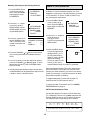
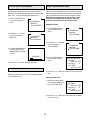
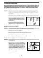
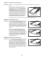
1
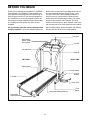
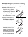
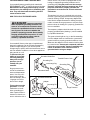
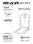
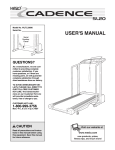
¨
Model No. WLTL62790
Serial No.
USER'S MANUAL
Find the serial number in the location
shown below. Write the serial number
in the space above for reference.
Serial
Number
Decal
QUESTIONS?
As a manufacturer, we are committed to providing complete
customer satisfaction. If you
have questions, or if there are
missing parts, we will guarantee
complete satisfaction through direct assistance from our factory.
TO AVOID UNNECESSARY DELAYS, PLEASE CALL DIRECT TO
OUR TOLL-FREE CUSTOMER
HOT LINE. The trained technicians on our Customer Hot Line
will provide immediate assistance, free of charge to you.
CUSTOMER HOT LINE:
1-800-999-3756
Mon.ÐFri., 6 a.m.Ð6 p.m. MST
CAUTION
Read all precautions and instructions in this manual before using
this equipment. Save this manual
for future reference.
Visit our website at
www.weslo.com
new products, prizes,
fitness tips, and much more!
¨
TABLE OF CONTENTS
IMPORTANT PRECAUTIONS . . . . . . . . . . . . . . . . . . . . . . . . . . . . . . . . . . . . . . . . . . . . . . . . . . . . . . . . . . . . . . . . .3
BEFORE YOU BEGIN . . . . . . . . . . . . . . . . . . . . . . . . . . . . . . . . . . . . . . . . . . . . . . . . . . . . . . . . . . . . . . . . . . . . . . .6
ASSEMBLY . . . . . . . . . . . . . . . . . . . . . . . . . . . . . . . . . . . . . . . . . . . . . . . . . . . . . . . . . . . . . . . . . . . . . . . . . . . . . . .7
TREADMILL OPERATION . . . . . . . . . . . . . . . . . . . . . . . . . . . . . . . . . . . . . . . . . . . . . . . . . . . . . . . . . . . . . . . . . . . .9
TELEVISION OPERATION . . . . . . . . . . . . . . . . . . . . . . . . . . . . . . . . . . . . . . . . . . . . . . . . . . . . . . . . . . . . . . . . . .12
HOW TO FOLD AND MOVE THE TREADMILL . . . . . . . . . . . . . . . . . . . . . . . . . . . . . . . . . . . . . . . . . . . . . . . . . .18
TROUBLE-SHOOTING . . . . . . . . . . . . . . . . . . . . . . . . . . . . . . . . . . . . . . . . . . . . . . . . . . . . . . . . . . . . . . . . . . . . .19
CONDITIONING GUIDELINES . . . . . . . . . . . . . . . . . . . . . . . . . . . . . . . . . . . . . . . . . . . . . . . . . . . . . . . . . . . . . . .22
PART LIST . . . . . . . . . . . . . . . . . . . . . . . . . . . . . . . . . . . . . . . . . . . . . . . . . . . . . . . . . . . . . . . . . . . . . . . . . . . . . . .23
ORDERING REPLACEMENT PARTS . . . . . . . . . . . . . . . . . . . . . . . . . . . . . . . . . . . . . . . . . . . . . . . . . .Back Cover
LIMITED WARRANTY . . . . . . . . . . . . . . . . . . . . . . . . . . . . . . . . . . . . . . . . . . . . . . . . . . . . . . . . . . . . . . .Back Cover
Note: An EXPLODED DRAWING is attached in the center of this manual.
WARNING:
Before beginning this or any exercise program, consult your physician. This
is especially important for persons over the age of 35 or persons with pre-existing health problems.
Read all instructions before using. ICON assumes no responsibility for personal injury or property
damage sustained by or through the use of this product.
2
IMPORTANT PRECAUTIONS
WARNING:
To reduce the risk of burns, fire, electric shock, or injury to persons, read the
following important precautions and information before operating the treadmill.
1. It is the responsibility of the owner to ensure
that all users of this treadmill are adequately
informed of all warnings and precautions.
13. Always wear athletic shoes when using the
treadmill. Never use the treadmill with bare
feet, wearing only stockings, or in sandals.
2. Use the treadmill only as described in this
manual.
14. Inspect and tighten all parts of the treadmill
regularly.
3. The treadmill is intended for home use only.
Do not use the treadmill in a commercial,
rental, or institutional setting.
15. The treadmill operates on 120 V, 60 Hz, AC
power only. Consult your dealer before connecting the treadmill if you do not know the
AC voltage in your area, as incorrect voltage
might damage the treadmill or TV. Never connect the treadmill to other than the specified
voltage such as 50 Hz or to direct current.
4. Place the treadmill on a level surface, with
eight feet of clearance behind it. To protect
the floor or carpet from damage, place a mat
under the treadmill.
16. When connecting the power cord (see HOW
TO PLUG IN THE POWER CORD on page 9),
plug the power cord into a surge protector
(not included) and plug the surge protector
into a grounded circuit capable of carrying 15
or more amps. No other appliance should be
on the same circuit. Do not overload the wall
outlets as this can result in a risk of electric
shock, fires, and other hazards.
5. Slots and openings in the treadmill and TV
are provided for ventilation, to ensure reliable
operation, and to help prevent overheating.
These openings must not be blocked or covered. Do not place the treadmill on any surface that blocks openings or near a radiator
or other heat source.
6. Keep the treadmill indoors, away from moisture and dust. Do not place the treadmill in a
garage or covered patio or near water.
17. Use only a UL-listed surge protector, rated at
15 amps, with a 14-gauge cord of five feet or
less in length. Do not use an extension cord.
7. Do not operate the treadmill where aerosol
products are used or where oxygen is being
administered.
18. The power cord and the surge protector
should be positioned so they are not likely to
be walked on or pinched by items placed
upon or against them; pay particular attention to the cords at the plugs, the convenience receptacles, and the point where the
power cord exits the treadmill. Keep the
power cord and the surge protector away
from heated surfaces.
8. You must be able to safely lift 45 pounds (20
kg) in order to raise or lower the treadmill.
9. Keep children under the age of 12 and pets
away from the treadmill at all times.
10. The treadmill should not be used by persons
weighing more than 250 pounds.
19. Do not operate the treadmill if the power cord
or plug is damaged or if the treadmill is not
working properly.
11. Never allow more than one person on the
treadmill at a time.
20. If an outside antenna or cable system is connected, be sure that the antenna or cable system is grounded so as to provide some protection against voltage surges and built-up
static charges. Section 810 of the National
Electrical Code, ANSI/NFPA No. 70-1984,
12. Wear appropriate exercise clothing when
using the treadmill. Do not wear loose clothing that could become caught in the treadmill. Athletic support clothes are recommended for both men and women.
3
29. The graphic symbols on the back cover of the
TV mean the following:
provides information with respect to proper
grounding of the mast and supporting structure, grounding of the lead-in wire to an antenna discharge unit, size of grounding conductors, location of antenna discharge unit,
connection to grounding electrodes, and requirements for the grounding electrode.
The lightning flash with arrowhead
symbol within an equilateral triangle is intended to alert the user to
the presence of uninsulated Òdangerous voltageÓ within the TVÕs enclosure
that may be of sufficient magnitude to constitute a risk of electric shock to persons.
21. An outside antenna system should not be located in the vicinity of overhead power lines
or other electric light or power circuits, or
where it can fall into such power lines or circuits. When installing an outside antenna
system, extreme care should be taken to
keep from touching such power lines or circuits as contact with them might be fatal.
The exclamation point within an
equilateral triangle is intended to
alert the user to the presence of important operating and maintenance
(servicing) instructions in this manual.
22. Never start the treadmill while you are standing on the walking belt. Always hold the
handrails while using the treadmill.
30. Unplug the treadmill from the wall outlet and
refer servicing to qualified service personnel
under the following conditions:
23. The treadmill is capable of high speeds.
Adjust the speed in small increments to
avoid sudden jumps in speed.
¥ When the power cord or plug is damaged
¥ If liquid has been spilled, or objects have
fallen into the treadmill
24. Never leave the treadmill unattended while it
is running. Move the on/off switch to the ÒoffÓ
position when the treadmill is not in use.
¥ If the treadmill has been exposed to water
¥ If the treadmill or TV does not operate normally when the operating instructions are
followed. Adjust only those controls that
are covered by the operating instructions,
as improper adjustment of other controls
may result in damage and will often require
extensive work by a qualified technician to
restore normal operation
25. To protect the treadmill and TV during lightning storms, unplug the power cord from the
wall outlet and disconnect the antenna or
cable system. This will prevent damage due
to lightning and power line surges.
26. Never drop or insert any object into any
opening.
27.
¥ If the treadmill has been dropped
DANGER: Always unplug the power
¥ When the treadmill exhibits a distinct
change in performance.
cord immediately after use, before cleaning
the treadmill, and before performing the
maintenance and adjustment procedures described in this manual. Never remove the
motor hood unless instructed to do so by an
authorized service representative. Servicing
other than the procedures in this manual
should be performed by an authorized service representative only.
31. When replacement parts are required, be
sure the service technician uses replacement
parts specified by the manufacturer or those
that have the same characteristics as the
original part. Unauthorized substitutions may
result in fire, electric shock, or other hazards.
32. Upon completion of any service or repairs to
the treadmill or TV, ask the service technician
to perform safety checks to determine that
28. To reduce the risk of electric shock, do not
remove the cover or back of the TV. There are
no user serviceable parts inside. Refer servicing to qualified service personnel.
4
¥ Use jumper wire not smaller than No. 6
AWG (13.3mm2) copper, or the equivalent
when a separate antenna-grounding electrode is used. See NEC Section 810-21 (j).
the unit is in proper operating condition
(refer to the drawing below).
¥ Use No. 10 AWG (5.3mm2) copper, No. 8
AWG (8.4mm2) aluminum, No. 17 AWG
(1.0mm2) copper-clad steel or bronze wire,
or larger as a ground wire.
Note to CATV system installer: This reminder is
provided to call the CATV system installerÕs attention to Article 820-40 of the NEC that provides
guidelines for proper grounding and, in particular, specifies that the cable ground shall be connected to the grounding system of the building,
as close to the point of cable entry as practical.
¥ Secure antenna lead-in and ground wires to
house with stand-off insulators spaced
from 4 to 6 feet (1.22 to 1.83m) apart.
¥ Mount antenna discharge unit as close as
possible to where the lead-in enters the
house.
Power Lines
Ground
Clamp
Service
Entrance
Conductors
To External Antenna
Terminal of Treadmill
Service
Entrance
Equipment
Ground
Wire
Power Service Grounding
Electrode System (e.g.
Interior Metal Water Pipe)
Ground
Clamps
Standoff
Insulators
Mast
Antenna
Lead-in Wire
Antenna
Discharge Unit
Ground Wire
Ground
Bonding
Clamps
Jumper
Optional Antenna Grounding Electrode Driven 8
Feet (2.44m) Into The Earth (If Required By Local
Codes). See NEC Section 810Ð21 (f).
SAVE THESE INSTRUCTIONS
The decal shown below has been placed on your treadmill in
the indicated location. If the decal is missing or illegible,
please call our Customer Service Department, toll-free, at
1-800-999-3756 to order a free replacement decal. Apply the
decal in the location shown.
Note: The decal is shown at 38% of actual size.
5
BEFORE YOU BEGIN
Thank you for selecting the new WESLO¨ CADENCE
TV36 treadmill. The CADENCE TV36 treadmill combines advanced technology with innovative design to
help you get the most from your exercise program in
the convenience of your home. And when youÕre not
exercising, the unique CADENCE TV36 can be folded
up, requiring less than half the floor space of other
treadmills.
please call our Customer Service Department toll-free
at 1-800-999-3756, Monday through Friday, 6 a.m.
until 6 p.m. Mountain Time (excluding holidays). To
help us assist you, please note the product model
number and serial number before calling. The model
number of the treadmill is WLTL62790. The serial
number can be found on a decal attached to the treadmill (see the front cover of this manual for the location).
For your benefit, read this manual carefully before
using the treadmill. If you have additional questions,
Before reading further, please familiarize yourself with
the parts that are labeled in the drawing below.
Television
Water Bottle
Holder (Bottle
not included)
Console
Storage Latch
Key/Clip
Handrail
LEFT SIDE
RIGHT SIDE
Walking Belt
On/Off Switch
Circuit
Breaker
Foot Rail
Power Cord
Front
Wheel
Cushioned Walking Platform
Rear Roller
Adjustment Bolts
6
ASSEMBLY
Assembly requires two people. Set the treadmill in a cleared area and remove all packing materials. Do not
dispose of the packing materials until assembly is completed. Assembly requires the included allen wrench
and your own phillips screwdriver
.
Note: The underside of the treadmill walking belt is coated with high-performance lubricant. During shipping, a
small amount of lubricant may be transferred to the top of the walking belt or the shipping carton. This is a normal
condition and does not affect treadmill performance. If there is lubricant on top of the walking belt, simply wipe off
the lubricant with a soft cloth and a mild, non-abrasive cleaner.
1. With the help of a second person, carefully raise the
Uprights (61) until the treadmill is in the position shown.
1
61
Identify the Right Extension Leg (101) by looking at the
sticker on the underside. Insert the Right Extension Leg
into the right side of the treadmill as shown. (Note: It may
be helpful to tip the Uprights (61) in the direction shown
by the arrow as you insert the Extension Leg.) Attach the
Extension Leg with a Long Extension Leg Screw (18).
Make sure to push on the head of the Extension Leg
Screw while tightening it.
18
Bracket
Attach the Left Extension Leg (not shown) in the same way.
2. Insert the upper end of a Handrail (53) into the right
Upright (61) as shown. Note: It will be necessary to
pivot the Handrail to the side and back repeatedly
(see arrow A) while pushing on the Handrail (see
arrow B) to insert it fully into the Upright. Next, pivot
the lower end of the Handrail down and push it against
the bracket on the Right Extension Leg.
101
2
B
61
53
53
61
Insert the other Handrail (53) into the left Upright (61) in
the same way.
A
Bracket
3. Make sure that the hole in the Handrail (53) is aligned with
the hole in the bracket on the Extension Leg (101). If the
holes are not aligned, rotate the Handrail away from the
treadmill and slide the upper end of the Handrail out of the
Upright (61) slightly. Then, rotate the lower end of the
Handrail back to the position shown by the dotted line in
drawing 2. Repeat, if necessary, until the holes are
aligned. Make sure that the lower end of the Handrail is
against the bracket on the Extension Leg. Using the included allen wrench, tighten a Handrail Screw (77) into
the bracket and the Handrail.
Attach the other Handrail (not shown) in the same way.
7
3
61
77
53
101
4. Remove the Lock Knob (54) from the Lock Pin (59).
4
Press the Lock Knob Sleeve (55) into the left Upright (61).
54
Make sure that the Lock Pin Collar (57) and the Spring
(56) are on the Lock Pin. Insert the Lock Pin into the left
Upright (61) and tighten the Lock Knob onto the Lock Pin.
56
57
59
55
61
5. Note the location of the 75 ohm antenna terminal on
the treadmill (for clarity, the treadmill is shown in the
storage position). For the television to operate properly, an antenna, a CATV cable, or a VCR must be connected to the 75 ohm antenna terminal.
5
75 Ohm
Antenna
Terminal
If you are using an antenna, it must be properly connected and adjusted for optimal reception. Refer to ANTENNA CONNECTIONS on pages 12 and 13 to properly
connect an antenna.
If you are using a CATV cable, refer to CATV CABLE
CONNECTION on page 13 to properly connect the cable.
If you are using a VCR, refer to HOW TO CONNECT A
VCR on page 17 to properly connect the VCR. The VCR
must be turned on, a videocassette must be properly
inserted, and the VCR must be playing. Refer to your
VCR userÕs manual for operating instructions.
6. The console requires two "AA" batteries (not included).
Alkaline batteries are recommended. To install batteries,
first open the Battery Cover (98) as shown. Press two
batteries into the battery compartment, with the negative
ends of the batteries (marked ÒÐÓ) touching the springs.
Close the battery cover, push up on the battery cover tab,
and then push the tab forward as shown. Be sure that the
tab locks into place.
6
Batteries
98
Battery
Cover Tab
7. Make sure that all parts are tightened before you use
the treadmill. Note: The ratchet screws on the adjustable
rear incline are factory set and should not be adjusted.
Keep the included allen wrench in a secure place. The
allen wrench is used to adjust the walking belt (see page
20). To protect the floor or carpet from damage, place a
mat under the treadmill.
8
7
Ratchet
Screws
THE PERFORMANT LUBETM WALKING BELT
Your treadmill features a walking belt coated with
PERFORMANT LUBETM, a high-performance lubricant.
IMPORTANT: Never apply silicone spray or other
substances to the walking belt or the walking platform. They will deteriorate the walking belt and
cause excessive wear.
electric shock. This product is equipped with a cord
having an equipment-grounding conductor and a
grounding plug. Plug the power cord into a surge
protector, and plug the surge protector into an appropriate outlet that is properly installed and
grounded in accordance with all local codes and
ordinances.
This product is for use on a nominal 120-volt circuit,
and has a grounding plug that looks like the plug illustrated in drawing 1 below. A temporary adapter that
looks like the adapter illustrated in drawing 2 may be
used to connect the surge protector to a 2-pole receptacle as shown in drawing 2 if a properly grounded outlet is not available.
HOW TO PLUG IN THE POWER CORD
DANGER:
Improper connection
of the equipment-grounding conductor can
result in an increased risk of electric shock.
Check with a qualified electrician or serviceman if you are in doubt as to whether the
product is properly grounded. Do not modify
the plug provided with the productÑif it will
not fit the outlet, have a proper outlet installed by a qualified electrician.
The temporary adapter should be used only until a
properly grounded outlet (drawing 1) can be installed
by a qualified electrician.
The green-colored rigid ear, lug, or the like extending
from the adapter must be connected to a permanent
ground such as a properly grounded outlet box cover.
Whenever the adapter is used it must be held in place
by a metal screw. Some 2-pole receptacle outlet box
covers are not grounded. Contact a qualified electrician to determine if the outlet box cover is
grounded before using an adapter.
Your treadmill, like any other type of sophisticated
electronic equipment, can be seriously damaged by
sudden voltage changes in your homeÕs power.
Voltage surges, spikes, and noise interference can result from weather conditions or from other appliances
being turned on or off.
To decrease the pos1
sibility of your treadGrounded Outlet Box
mill being damaged,
Treadmill Power Cord
always use a surge
Grounding Pin
protector (not included) with your
Grounding Plug
Grounding Plug
treadmill.
Surge protectors are
sold at most hardware
stores and department
stores. Use only a ULlisted surge protector,
rated at 15 amps, with a
14-gauge cord of five
feet or less in length.
This product must be
grounded. If it should
malfunction or break
down, grounding provides a path of least resistance for electric current to reduce the risk of
Grounding Pin
Grounded Outlet
2
Grounded Outlet Box
Adapter
Grounding Pin
Grounding Plug
Lug
Metal Screw
9
Surge Protector
CONSOLE DIAGRAM
STEP-BY-STEP CONSOLE OPERATION
Note: The console requires two ÒAAÓ batteries (not included). If you have not installed batteries, see assembly step 6 on page 8.
Locate the on/off
switch near the power
cord. Make sure that
the on/off switch is in
the on position. In addition, make sure that
the power cord is properly plugged in (see
HOW TO PLUG IN THE POWER CORD on page 9).
Note: If there is a thin sheet of clear plastic
on the face of the console, remove it before
operating the console.
When you are ready to
begin exercising, step
onto the foot rails of
the treadmill. Find the
clip attached to the
key, and slide the clip
onto the waistband of
your clothing.
Clip
Follow the steps on page 11 to operate the console.
FEATURES OF THE CONSOLE
The treadmill console is designed to make your workouts more enjoyable and effective. As you exercise,
the integral color TV will show your favorite television
programs while the LCD displays show the elapsed
time, the distance you have walked, the approximate
numbers of calories and fat calories you have burned,
and the speed of the walking belt.
CAUTION:
Before operating the
console, read the following precautions.
¥ Do not stand on the walking belt when turning on the power or starting the walking belt.
¥ Always wear the clip (see the drawing
above) while using the treadmill. When the
key is pulled from the console, the walking
belt will stop.
To operate the treadmill, follow the instructions at the
right.
To operate the color TV, follow the instructions beginning on page 12. IMPORTANT: For the television to
operate properly, an antenna, a CATV cable, or a
VCR must be connected to the 75 ohm antenna
terminal on the treadmill.
¥ The treadmill is capable of high speeds.
Adjust the speed in small increments.
¥ Never leave the treadmill unattended while
it is running.
If you are using an antenna, it must be properly connected and adjusted. Refer to ANTENNA CONNECTIONS on pages 12 and 13 to properly connect an antenna.
¥ To reduce the possibility of electric shock,
keep the console dry. Avoid spilling liquids
on the console and use only a sealable
water bottle.
If you are using a CATV cable, refer to CATV CABLE
CONNECTION on page 13 to connect the cable.
If you are using a VCR, refer to HOW TO CONNECT
A VCR on page 17 to properly connect the VCR.
10
1
CALS/FAT CALS/
SPEED displayÑThis
display shows the approximate numbers of
calories and fat calories
you have burned. (See
FAT BURNING on page 22.) In addition, the display shows the speed of the walking belt, in miles
per hour. Every seven seconds, the display will
change. Arrows in the display will indicate which
information is currently shown.
Insert the key into the console.
Inserting the key
will not turn on the
displays. The displays will turn on
when the ON/
RESET button is
pressed or when
the walking belt is
started. Note: If you just installed batteries, the
displays will already be on.
2
To reset the displays at
any time, press the
ON/RESET button.
Reset the speed control.
Slide the speed
control to the
RESET position.
Note: Each time
the walking belt is
stopped, the
speed control
must be moved to
the RESET position before the walking belt
can be restarted.
3
5
Step onto the foot rails, stop the walking belt, and
remove the key from the console. The displays will
turn off about five minutes after the key is removed. Note: Any time that the walking belt is
stopped and the ON/RESET button is not
pressed for five minutes, the displays will automatically turn off in order to conserve the
batteries.
Start the walking belt.
After you have
moved the speed
control to the
RESET position,
slowly slide it to the
right until the walking belt begins to
move at slow
speed. Carefully step onto the walking belt and
begin exercising. Change the speed of the walking
belt as desired by sliding the speed control.
HOW TO CHANGE THE INCLINE OF THE TREADMILL
The incline of the treadmill can be changed by raising
or lowering the back end. Before changing the incline, remove the key and unplug the power cord.
Hold the
rear roller
endcap with
both hands.
When the
back end of
the treadmill
Hold the Rear
Incline
is in the lowRoller Endcap
Leg
in these locations
est position,
the incline is
about 10%.
Raise the back end until it clicks into position. (Note: It
may be necessary to shake the treadmill lightly so that
it clicks into position.) The incline will then be about
7%. Raise the back end again until it clicks into position. The incline will then be about 3%. To lower the
back end, raise it past the highest position and then
lower it. CAUTION: Before exercising, push on the
back of the treadmill to make sure that the incline
legs are locked in position. Do not place objects
under the treadmill to change the incline; change
the incline only as described above.
To stop the walking belt, step onto the foot rails
and slide the speed control to the RESET position.
4
When you are finished exercising, stop the
walking belt and remove the key.
Monitor your progress with the LCD displays.
TIME/DISTANCE displayÑThis display
shows the elapsed time
and distance that you
have walked or run, in
miles. Every seven seconds, the display will change from one number to
the other. Arrows in the display will show which
number is currently shown.
11
TELEVISION OPERATION
DIAGRAM OF THE TELEVISION
3
FEATURES OF THE TELEVISION
¥ Blackstripe picture tube
¥ 181 cable-ready channels (68 standard TV channels
and 113 cable channels)
¥ Full-featured on-screen display
¥ User-friendly menu-driven TV controls
¥ Video and audio input jacks
¥ Real time clock with one on-timer and one off-timer
¥ Mono audio
¥ Earphone jack
¥ LED power indicator
¥ Auto memory and auto search for TV channel
¥ Automatically skips unavailable channels in your area
5
1
2
6
7
4
8
9
Note: If desired, the TV can be viewed without the
treadmill being used. Make sure that the on/off switch
located near the power cord is in the ÒonÓ position.
(See the drawing near the top of page 10.)
ANTENNA CONNECTIONS
1. Power indicator (Note: The power indicator will
remain on whenever the on/off switch is on.)
2. POWER button
3. CHANNEL ▲ and ▼ buttons
4. VOLUME + and Ð buttons
5. Compartment door (IMPORTANT: The treadmill
and TV, like any other electronic equipment,
can be damaged by static electricity. Before
touching the controls behind the compartment
door, touch one of the treadmill handrails to
discharge static electricity.)
6. TV/CATV button
7. TV/AV button
8. Pop-up MENU button
9. Earphone Jack
Indoor Antenna
1. Place the VHF
antenna in the
desired location. Connect
the 300 ohm
flat wire to the
screws on the
300 ohm to 75
ohm adapter.
Screwdriver
VHF 300
Ohm Flat
Wire
300 to 75 Ohm Adapter
2. Connect the
300 to 75 ohm
adapter to the
75 ohm antenna
terminal on the
treadmill. (See
assembly drawing 5 on page 8
to find the location of the terminal.)
12
VHF Rod
Antenna
300 to 75 Ohm
Adapter
75 Ohm
Terminal
Outdoor Antenna
BASIC TV OPERATION
Outdoor antennas are subject to weathering that can
reduce signal quality. Inspect the antenna and lead-in
wiring before connecting the antenna. Any service center can explain the various outdoor antennas available.
Read the important
precautions on pages
3 to 5 of this manual.
Before operating the TV,
make sure that the
on/off switch located
near the power cord is
in the ÒonÓ position. In
addition, make sure that the power cord is properly
plugged in (see page 9).
Combination
VHF/UHF Antennas
300 Ohm
Flat Wire
Turning on the Power
To turn on the TV, press the POWER button on the TV.
300 to 75
Ohm Adapter
75 Ohm
Coaxial Cable
75 Ohm
Terminal
on Treadmill
Volume Control
To adjust the volume to the desired level, press the
VOLUME + or Ð button.
75 Ohm CATV Cable
The sound level will be
shown by a bar on the TV
screen. As the sound level is
increased, the bar will move
to the right. As the sound
VOLUME
level is decreased, the bar
will move to the left. Note: If
no broadcasting signal is received, the sound will be muted and the volume control
will be disabled.
300 Ohm Flat Wire
1.
Refer to the drawing above. Connect the 300 ohm
flat wire to the 300 ohm to 75 ohm adapter.
2.
Push the end of the 300 ohm to 75 ohm adapter
into the 75 ohm antenna terminal on the treadmill.
(See assembly drawing 5 on page 8 to find the location of the terminal.)
Skip Mode
75 Ohm Coaxial Cable
Press the CHANNEL ▲ or ▼ button to select memorized channels, skipping over empty channels. Hold
down the CHANNEL ▲ or ▼ button to change channels
continuously. Note: If no channels are memorized, the
TV will switch to the SEARCH mode.
Refer to the drawing above. Connect the 75 ohm coaxial cable directly to the 75 ohm antenna terminal. (See
assembly drawing 5 on page 8 to find the location of
the terminal.)
Search Mode
CATV CABLE CONNECTION
Press the CHANNEL ▲ or ▼ button to search for the
next available channel. Hold down the CHANNEL ▲ or
▼ button to search through all available channels.
1. Remove the VHF 300 to 75 ohm adapter or the VHF
cable from the antenna terminal. (See assembly drawing 5 on page 8 to find the location of the terminal.)
2. Connect the CATV
cable (75 ohm coaxial
cable) to the 75 ohm
antenna terminal on
the treadmill.
Note: Before selecting channels with the CHANNEL ▲
or ▼ button, the channels must be set into the TVÕs
memory. See MEMORIZING CHANNELS on page 14.
75 Ohm CATV Cable
VHF 75 Ohm Jack
13
Erasing Channels
CHANNEL PROGRAMMING
After all channels available in your area have been set
into memory, you can erase unwanted channels by following the steps below:
Memorizing Channels
The TV is equipped with a channel memorizing function that allows you to step up or down from the current
channel to the next channel set into memory. Before
channels can be selected in this way, they must be set
into the TVÕs memory. Note: When programming
channels, if no buttons are pressed for four seconds, the TV will return to the normal screen.
1. Select the unwanted channel by using the CHANNEL
▲ and ▼ button.
2. Press the MENU button
to turn on the pop-up
menu. Press the MENU
button again to select CH
MEMORY.
Automatic Memory Tuning
1. Press the MENU button
to turn on the pop-up
menu in the TV mode or
CATV mode. Press the
MENU button again to
select CH MEMORY
(channel memory).
2. Press the MENU button
again to select AUTO
MEMORY.
CH MEMORY
ANALOG
CLOCK/TIMER
3. Press the + or Ð button to
move the arrow to MEMORY ADD¥ERASE.
Select MEMORY
ADD¥ERASE by pressing
the MENU button.
AUTO MEMORY
SEARCH/SKIP
MEMORY ADD
¥ERASE
TV/CATV
4. Press the Ð button to
erase the stored channel
from memory. The channel number will change
from green to red.
3. Press the + button to
start AUTO MEMORY.
TV
07
The TV will begin setting
into memory all the channels available in your
AUTO MEMORY
area. When no broadcast
START [+]
signal is detected on a
channel, the channel is
erased from memory. When a signal is detected, the
channel is stored in memory and the next channel is
selected.
This process will be repeated until the highest
channel is reached. It then
stops at the lowest channel
stored in memory, and returns to a normal screen
after four seconds. The TV
will then be in the SKIP
mode.
TV
CH MEMORY
ANALOG
CLOCK/TIMER
AUTO MEMORY
SEARCH/SKIP
MEMORY ADD
¥ERASE
TV/CATV
TV
07
CHANNEL MEMORY
END
ERASE
[+]
[Ð]
Adding Channels
Channels that are not in memory can be stored manually. To manually store a channel, follow the steps
above, but press the + button when MEMORY ADD¥
ERASE is selected. The channel will be stored in
memory, and the channel number will change from red
to green.
07
AUTO MEMORY
END
14
Manually Searching for and Storing Channels
1. Press the MENU button
to turn on the pop-up
menu. Press the MENU
button again to select
CH MEMORY.
2. Press the + or Ð button
to move the arrow to
SEARCH/SKIP. Select
SEARCH/SKIP by pressing the MENU button.
3. Press the Ð button to select the SEARCH mode.
The TV will return to the
normal screen after four
seconds.
CABLE TV (CATV) OPERATION
In addition to normal broadcast reception, the TV is
equipped to receive up to 125 cable channels (113 and
12 TV channels). To use the TV with a cable TV system, following the steps below.
CH MEMORY
ANALOG
CLOCK/TIMER
1. Press the MENU button
to turn on the pop up
menu. Press the MENU
button again to select CH
MEMORY.
AUTO MEMORY
SEARCH/SKIP
MEMORY ADD
¥ERASE
TV/CATV
2. Press the + or Ð button to
move the arrow to
TV/CATV. Select
TV/CATV by pressing the
MENU button.
CHANNEL UP/DOWN
SKIP
:
[+]
SEARCH :
[Ð]
CH MEMORY
ANALOG
CLOCK/TIMER
AUTO MEMORY
SEARCH/SKIP
MEMORY ADD
¥ERASE
TV/CATV
3. Press the MENU button
to cycle through the four
TV 07
channel modes: (1) TV;
(2) STD (Standard) for
cable TV mode; (3) HRC
(Harmonic Related
Carrier) for cable TV subscriber; (4) IRC (Incremental Related Carrier) for cable TV subscriber.
@@@@@@@@e?
@@@@@@@@e?@@@@@@@@?e@@@@@@@@e?@@@@@@@@?e@@@@@@@@e?
@@@@@@@@e?
@@@@@@@@e?@@@@@@@@?e@@@@@@@@e?@@@@@@@@?e@@@@@@@@e?@@@@@@@@
@@@@@@@@
@@h?
@@
@@h?
@@
@@h?
@@
@@h?
@@
@@h?
@@
@@h?
@@
@@
@@
@@
@@
@@
@@
@@
@@
4. Press the CHANNEL ▲ or ▼ button to start searching. It will stop whenever an available channel is
found.
@@
@@
@@
@@
@@
@@
@@
@@
@@
@@
@@
@@
@@
@@
@@
@@
@@
@@
@@
@@
@@
@@
@@
@@
@@
@@
@@
@@
@@
@@
@@
@@
@@
@@
@@
@@
@@
@@
@@
@@
@@
@@
@@
@@
@@
@@
@@
@@
@@g
@@g
@@g
@@g
@@g
@@g
@@@@@@@@
@@@@@@@@ ?@@@@@@@@?e@@@@@@@@e?@@@@@@@@?e@@@@@@@@e?@@@@@@@@
?@@@@@@@@?e@@@@@@@@e?@@@@@@@@?e@@@@@@@@e?@@@@@@@@
5. If you do not want to store the channel in memory,
press the CHANNEL ▲ or ▼ button again. To store
the channel in memory, refer to ADDING CHANNELS at the left.
@@
@@
@@
@@
@@
@@
@@
@@
?@@
?@@
?@@
?@@
?@@
?@@
?@@@@@@@@
?@@@@@@@@
Once the appropriate cable TV mode is selected, the
screen will return to normal after two seconds. Note:
Consult your cable company if you are not sure which
system you are using, or try different systems to obtain
the maximum number of channels.
6. Until all desired channels have been stored, return
to SEARCH/SKIP as described above and press the
+ button to return to the SKIP mode.
To toggle between the TV mode and the cable TV
mode, press the TV/CATV button on the TV.
To memorize cable TV channels, refer to CHANNEL
PROGRAMMING on page 14.
CATV Channel Reference Table
Use the table below to find which CATV channel your
TV is displaying. The top row (in bold) represents the
channel number shown on the TV screen; the bottom
row represents the corresponding CATV channel.
1, 2 . . . . 6 . . . . 13, 14 . . . . 26 . . . . 36, 37 . . . . 50 . . . . 65,
5A, 2 . . . . 6 . . . . 13, A . . . . M . . . . W, W+1 . . W+14 . .W+29,
66 . . . . 75 . . . . 86 . . . . 94, 95 . . . . 99, 100 . . . . 112 . . . . 125
W+30 . . W+39 . . W+50 . . W+58, A-5 . . A-1, W+59 . . W+71 . . W+84
15
PICTURE LEVEL ADJUSTMENTS
USING THE RECORDING TIMER
Picture level controls are preset to nominal levels. If
desired, you can individually adjust the contrast, brightness, color, or tint by following the steps below.
1. Press the MENU button
to turn on the pop-up
menu.
Your TV has the capability to turn on, switch to a channel for recording, and then turn off againÑall automatically. Follow the instructions below to use this feature.
Note: When setting the clock, the on timer, or the
off timer, if no buttons are pressed for four seconds, the TV will return to the normal screen.
CH MEMORY
ANALOG
CLOCK/TIMER
Setting the Clock
1. Press the MENU button
to turn on the pop-up
menu.
2. Press the + or Ð button
to move the arrow to
ANALOG.
CH MEMORY
ANALOG
CLOCK/TIMER
CH MEMORY
ANALOG
CLOCK/TIMER
2. Press the + or Ð button to
move the arrow to
CLOCK/TIMER.
3. Press the MENU button
to select CONTRAST,
BRIGHTNESS, COLOR,
or TINT.
CONTRAST
3. Press the MENU button
to turn on the setting
menu.
4. Press the + or Ð button to adjust the level.
CH MEMORY
ANALOG
CLOCK/TIMER
CLOCK AM 12:00
ON TIME
AM 12:00 OFF
ON CH 02
TV
OFF TIME
AM 12:00 OFF
SELECTING VIDEO INPUT
2. Press the + or Ð button to set the clock to the correct
time.
Press the TV/AV button on the TV to toggle between
TV and VIDEO input.
Setting the On Timer
1. After the clock has been
set, press the MENU button to select ON TIME.
CLOCK AM 12:00
ON TIME
AM 12:00 OFF
ON CH 02
TV
OFF TIME
AM 12:00 OFF
2. Press the + or Ð button to set the time that you want
the TV to turn on.
16
Setting the Channel to be Recorded
1. After the on timer has
been set, press the
MENU button repeatedly
to select ON CH (on
channel).
USING THE MENU FUNCTION
CLOCK AM 12:00
ON TIME
AM 12:00 OFF
ON CH 02
TV
OFF TIME
AM 12:00 OFF
When the menu is used, pressing the MENU button
will display a menu that allows selection of channel
memory, the clock, the on timer, the off timer, or picture level controls. When the MENU button is pressed,
the display will be as shown below.
2. Press the + button to cycle through the channels
until the desired channel is selected.
3. Press the Ð button to cycle through the four channel
modes: (1) TV, (2) STD, (3) HRC, (4) IRC.
After the channel has been set, press the MENU button to select the on/off setting mode of the on timer.
Pressing the + or Ð button at this point will change the
display to ÒON,Ó reset the seconds of the on timer, and
start the count.
CH MEMORY
ANALOG
CLOCK/TIMER
ANALOG
CLOCK/TIMER
TV Mode
Video Mode
HOW TO CONNECT A VCR
Setting the Off Timer
1. After a channel has been
set, press the MENU
button repeatedly to select OFF TIME.
Follow the steps below to connect your VCR (not included) to the treadmill. A CATV cable (75 ohm coaxial
cable) at least nine feet long is required.
CLOCK AM 12:00
ON TIME
AM 12:00 OFF
ON CH 02
TV
OFF TIME
AM 12:00 OFF
1. Connect one end of the CATV cable to the video
output jack on the VCR.
2. Plug in the power cord of the VCR. Refer to your
VCR userÕs manual for proper grounding instructions.
2. Press the + or Ð button to set the time that you want
the TV to turn off.
3. Connect the CATV cable to the 75 ohm antenna terminal on the treadmill. (See assembly drawing 5 on
page 8 to find the location of the terminal.
After the channel has been set, pressing the MENU
button will select the on/off setting mode of the off
timer. Pressing the + or Ð button at this point will
change the display to ÒON,Ó reset the seconds of the
off timer, and start the count.
To operate the VCR
with the TV, make sure
that the on/off switch located near the power
cord is in the ÒonÓ position, and that the power
cord is properly plugged
in (see page 9).
To turn on the TV, press the POWER button on the TV.
Make sure that the TV is on channel 3 or 4. Note: When
the treadmill is not in use, you may want to leave the
surge protector plugged in. Each time the power cord is
unplugged, the TV must go through an automatic channel resetting routine when the power is turned on again.
17
HOW TO FOLD AND MOVE THE TREADMILL
HOW TO FOLD THE TREADMILL FOR STORAGE
1
Before folding the treadmill, adjust the incline to the
lowest position. If this is not done, the treadmill may be
permanently damaged. Next, unplug the power cord.
CAUTION: You must be able to safely lift 45 pounds (20
kg) in order to raise, lower, or move the treadmill.
1. Hold the treadmill with your hands in the locations shown
at the right. CAUTION: To decrease the possibility of injury, bend your legs and keep your back straight. As
you raise the treadmill, make sure to lift with your legs
rather than your back. Raise the treadmill about halfway
to the vertical position.
2. Move your right hand to the position shown and hold the
treadmill firmly. Hold the lock knob with your left hand and
pull it to the left. Position the treadmill until the hole in the
side of the treadmill lines up with the lock pin. Slowly release the lock knob. Make sure that the pin on the lock
knob is fully insert into the hole in the frame.
To protect the floor or carpet from damage, place a
mat under the treadmill. Keep the treadmill out of
direct sunlight. Do not leave the treadmill in the storage position in temperatures above 85¡ Fahrenheit.
2
Hole
Knob
HOW TO MOVE THE TREADMILL
Before moving the treadmill, convert the treadmill to the storage position as described above. Make sure that the pin
on the lock knob is holding the treadmill frame securely.
1. Hold the handrails as shown and place one foot against a
wheel.
2. Tilt the treadmill back until it rolls freely on the front wheels.
Carefully move the treadmill to the desired location. Never
move the treadmill without tipping it back. To reduce
the risk of injury, use extreme caution while moving
the treadmill. Do not attempt to move the treadmill
over an uneven surface.
3. Place one foot on the base, and carefully lower the
treadmill until it is resting in the storage position.
Base
Front Wheels
HOW TO LOWER THE TREADMILL FOR USE
1. Refer to drawing 2 above. Hold the upper end of the treadmill with your right hand as shown. Using your left
hand, pull the lock knob to the left and hold it. Pivot the treadmill down until the frame is past the pin on the lock
know.
2. Refer to drawing 1 above. Hold the treadmill firmly with both hands, and lower the treadmill to the floor.
CAUTION: To decrease the possibility of injury, bend your legs and keep your back straight.
18
TROUBLE-SHOOTING
Most treadmill problems can be solved by following the steps below. Find the symptom that applies, and
follow the steps listed. If further assistance is needed, please call our Customer Service Department tollfree at 1-800-999-3756, Monday through Friday, 6 a.m. until 6 p.m. Mountain Time (excluding holidays).
PROBLEM: The power does not turn on
SOLUTION: a. Make sure that the power cord is plugged into a surge protector, and that the surge protector is
plugged into a properly grounded outlet. (See HOW TO PLUG IN THE POWER CORD on page
9.) Use only a UL-listed surge protector, rated at 15 amps, with a 14-gauge cord of five feet or
less in length.
b. After the power cord has been plugged in, make sure that the key is fully inserted into the console.
c. Check the circuit breaker located on the treadmill
near the power cord. If the switch protrudes as
shown, the circuit breaker has tripped. To reset the
circuit breaker, wait for five minutes and then press
the switch back in.
c
Tripped
Reset
Tripped
d. Check the on/off switch located on the treadmill
near the power cord. The switch must be in the on
position.
Reset
d
On
Position
PROBLEM: The power turns off during use
SOLUTION: a. Check the circuit breaker located on the treadmill frame near the power cord (see c. above). If the
circuit breaker has tripped, wait for five minutes and then press the switch back in.
b. Make sure that the power cord is plugged in.
c. Remove the key from the console. Reinsert the key fully into the console.
d. Make sure that the on/off switch is in the on position.
e. If the treadmill still will not run, please call our Customer Service Department, toll-free.
PROBLEM: The displays of the console do not function properly
SOLUTION: a. Check the batteries in the console. See assembly step 6 on page 8. Most problems are the result
of drained batteries.
a. Remove the key from the console and unplug the
power cord. Remove the screws from the hood and
carefully remove the hood. Locate the Reed Switch (9)
and the Magnet (8) on the left side of the Pulley (12).
Turn the Pulley until the Magnet is aligned with the
Reed Switch. Make sure that the gap between the
Magnet and the Reed Switch is about 1/8Ó. If necessary, loosen the Screw (39) and move the Reed
Switch slightly. Retighten the Screw. Re-attach the
hood, and run the treadmill for a few minutes to check
for a correct speed reading.
19
1/8Ó
9
89
Top
View
12
8
PROBLEM: The walking belt slows when walked on
SOLUTION: a. Use only a UL-listed surge protector, rated at 15 amps, with a 14-gauge cord of five feet or less in
length.
b. If the walking belt is overtightened, treadmill performance may decrease and the walking belt may become damaged. Remove the key and UNPLUG THE
POWER CORD. Using the allen wrench, turn both
rear roller adjustment bolts counterclockwise, 1/4 of a
turn. When the walking belt is properly tightened, you
should be able to lift each side of the walking belt 2 to
3 inches off the walking platform. Be careful to keep
the walking belt centered. Plug in the power cord, insert the key and run the treadmill for a few minutes.
Repeat until the walking belt is properly tightened.
b
2ÓÐ3Ó
Rear Roller Adjustment Bolts
c. If the walking belt still slows, please call our Customer Service Department, toll-free.
PROBLEM: The walking belt is off-center
SOLUTION: a. If the walking belt has shifted to the left, first remove
the key and UNPLUG THE POWER CORD. Using the
allen wrench, turn the left rear roller adjustment bolt
clockwise, and the right bolt counterclockwise, 1/4 of a
turn each. Be careful not to overtighten the walking belt.
Plug in the power cord, insert the key and run the treadmill for a few minutes. Repeat until the walking belt is
centered.
b. If the walking belt has shifted to the right, first remove the key and UNPLUG THE POWER CORD.
Using the allen wrench, turn the left rear roller adjustment bolt counterclockwise, and the right bolt clockwise,
1/4 of a turn each. Be careful not to overtighten the
walking belt. Plug in the power cord, insert the key and
run the treadmill for a few minutes. Repeat until the
walking belt is centered.
a
b
PROBLEM: The walking belt slips when walked on
SOLUTION: a. If the walking belt slips when walked on, first remove
the key and UNPLUG THE POWER CORD. Using the
allen wrench, turn both rear roller adjustment bolts
clockwise, 1/4 of a turn. When the walking belt is correctly tightened, you should be able to lift each side of
the walking belt 2 to 3 inches off the walking platform.
Be careful to keep the walking belt centered. Plug in the
power cord, insert the key and carefully walk on the
treadmill for a few minutes. Repeat until the walking belt
is properly tightened.
20
a
PROBLEM: TV reception is poor
SOLUTION: a. For the television to operate properly, good reception is necessary. If you are using an antenna,
make sure that it is properly connected and that it is adjusted for optimal reception. (See ANTENNA CONNECTIONS on page 12.)
b. Check for the problems listed below and follow the applicable instructions.
¥ Ignition (black spots or horizontal streaks that appear or a picture that flutters or drifts)ÑUsually
this is caused by interference from automobile ignition systems, neon lamps, electric drifts, or
other electric appliances. Try changing the position of the treadmill or other electric appliances
to correct the problem.
¥ GhostsÑGhosts are caused by the television signal following two pathsÑone is the direct path
and the other is reflected from tall buildings, hills, or other objects. Change the direction or position of the antenna to improve reception.
¥ SnowÑIf the TV is located in the fringe area of a television station where the signal is weak, the
picture may be marred by the appearance of small dots. If the signal is weak, it may be necessary to install an external antenna to improve the picture.
¥ Picture Size Variation: A slight picture size variation is normal when you adjust the CONTRAST
or BRIGHTNESS control.
Note: If one of these symptoms appears when the cable from a CATV company is connected, the
symptom may be caused by the local company broadcast.
21
CONDITIONING GUIDELINES
uses easily accessible carbohydrate calories for energy. Only after the first few minutes does your body
begin to use stored fat calories for energy. If your goal
is to burn fat, adjust the speed and incline of the treadmill until your heart rate is near the lowest number in
your training zone.
WARNING:
Before beginning this
or any exercise program, consult your physician. This is especially important for individuals over the age of 35 or individuals with preexisting health problems.
For maximum fat burning, adjust the speed and incline
of the treadmill until your heart rate is near the middle
number in your training zone.
The pulse sensor is not a medical device.
Various factors, including your movement,
may affect the accuracy of heart rate readings.
The sensor is intended only as an exercise aid
in determining heart rate trends in general.
Aerobic Exercise
If your goal is to strengthen your cardiovascular system, your exercise must be Òaerobic.Ó Aerobic exercise
is activity that requires large amounts of oxygen for
prolonged periods of time. This increases the demand
on the heart to pump blood to the muscles, and on the
lungs to oxygenate the blood. For aerobic exercise,
adjust the speed and incline of the treadmill until your
heart rate is near the highest number in your training
zone.
The following guidelines will help you to plan your exercise program. RememberÑthese are general guidelines only. For more detailed exercise information, obtain a reputable book or consult your physician.
EXERCISE INTENSITY
Whether your goal is to burn fat or to strengthen your
cardiovascular system, the key to achieving the
desired results is to exercise with the proper intensity.
The proper intensity level can be found by using your
heart rate as a guide. The chart below shows recommended heart rates for fat burning and aerobic exercise.
WORKOUT GUIDELINES
Each workout should include the following three parts:
A Warm-upÑStart each workout with 5 to 10 minutes
of stretching and light exercise. A proper warm-up increases your body temperature, heart rate and circulation in preparation for exercise.
Training Zone ExerciseÑAfter warming up, increase
the intensity of your exercise until your pulse is in your
training zone for 20 to 60 minutes. (During the first few
weeks of your exercise program, do not keep your
pulse in your training zone for longer than 20 minutes.)
Breathe regularly and deeply as you exerciseÑnever
hold your breath.
To find the proper heart rate for you, first find your age
near the bottom of the chart (ages are rounded off to
the nearest ten years). Next, find the three numbers
above your age. The three numbers define your Òtraining zone.Ó The lower two numbers are recommended
heart rates for fat burning; the higher number is the
recommended heart rate for aerobic exercise.
A Cool-downÑFinish each workout with 5 to 10 minutes of stretching to cool down. This will increase the
flexibility of your muscles and will help prevent post-exercise problems.
To measure your heart rate during exercise, use the
pulse sensor on the console. If your heart rate is too
high or too low, adjust the speed and incline of the
treadmill.
Exercise Frequency
To maintain or improve your condition, complete three
workouts each week, with at least one day of rest between workouts. After a few months, you may complete up to five workouts each week if desired.
Fat Burning
To burn fat effectively, you must exercise at a relatively
low intensity level for a sustained period of time.
During the first few minutes of exercise, your body
The key to success is to make exercise a regular and
enjoyable part of your everyday life.
22
PART LISTÑModel No. WLTL62790
R1099A
To locate the parts listed below, refer to the EXPLODED DRAWING attached in the center of this manual.
Key
No. Qty.
1
2
3
4
5
6
7
8
9
1
6
3
4
8
4
2
1
1
10
11
12
13
14
1
1
1
1
1
15
16
17
18
2
1
2
2
19
20
21
22
23
24
25
26
27
28
14
1
1
1
2
2
1
3
1
1
29
30
31
1
2
2
32
33
34
35
36
37
38
39
40
41
42
43
44
1
2
2
2
3
1
2
12
1
2
1
1
1
Description
Left Foot Rail
Hood Screw
Plastic Washer
Isolator
Isolator Screw
Platform Screw
Frame Pivot Nut
Magnet
Reed Switch/Sensor
Wire
Reed Switch Screw
Reed Switch Clip
Front Pulley/Roller
Console
Front Roller Adj.
Washer
Frame Pivot Spacer
Right Frame Rail
Belt Guide
Long Extension Leg
Screw
Belly Pan Fastener
Belly Pan
Walking Belt
Walking Platform
Rear Platform Screw
Ratchet Screw
Ratchet Pivot Bolt
Ratchet Screw
Ratchet Spring
Incline Leg Spacer
(long)
Ratchet
Incline Leg Pivot Bolt
Incline Leg Spacer
(short)
Incline Leg
Incline Wheel Bolt
Incline Wheel
Incline Wheel Nut
Wheel Nut
Incline Leg Plate
Belly Pan Screw
Screw
Ground Wire
Rear Roller Adj. Bolt
Warning Decal
Rear Endcap
Allen Wrench
Key
No. Qty.
45
46
47
48
49
50
51
52
53
54
55
56
57
58
59
60
61
62
63
64
65
66
67
68
69
70
71
72
73
74
75
76
77
78
79
80
81
82
83
84
85
86
87
88
89
90*
91
92
93
1
1
1
1
4
1
1
1
2
1
1
1
1
1
1
1
1
4
1
4
4
4
1
1
1
1
8
13
1
1
2
2
2
1
11
2
2
2
1
2
1
1
1
3
1
1
1
1
1
Description
Frame
Rear Roller
Left Extension Leg
4Ó Cable Tie
8Ó Cable Tie
Releasable Tie
Tie Screw
Cable Tie Clamp
Handrail
Lock Knob
Lock Knob Sleeve
Spring
Lock Pin Collar
Pin Clip
Lock Pin
Wire Harness
Upright Base
TV Bracket Nut
TV Bracket
TV Bracket Bolt
TV Screw
Console Base Screw
Key/Clip
Console Base
TV
Console Base Plate
Base Plate Screw
Small Screw
Motor Hood
Hood Shield
Frame Pivot Bolt
Frame Pivot Washer
Handrail Screw
On/Off Switch
Washer
Wheel Bolt
Wheel
Wheel Nut
Power Cord
Handrail Screw
Grommet
Choke
Circuit Breaker
Key Switch Screw
Motor Pivot Bolt
Motor Assembly
Motor
Pulley/Flywheel/Fan
Motor Tension Nut
23
Key
No. Qty.
94
95
1
1
96
1
97
98
99
100
101
102
103
104
105
106
107
108
1
1
1
1
1
1
1
1
1
1
4
2
109
110
111
112
113
114
115
116*
4
1
2
4
8
1
3
1
117*
1
#
#
#
#
#
#
1
1
1
1
1
1
Description
Motor Tension Bolt
Motor Tension
Washer
Motor Tension Star
Washer
Key Switch
Battery Cover
Motor Belt
Shock
Right Extension Leg
Controller
Motor Belly Pan
Motor Pivot Nut
Speed Potentiometer
Speed Control Knob
Base Pad
Motor Belly Pan
Screw
Isolator Spacer
Plastic Sleeve
Plastic Spacer
1 1/2Ó Screw
Isolator Screw
TV Cable
Wire Clip
Left Extension Leg
Assembly
Right Extension Leg
Assembly
8Ó Blue Wire, M/F
4Ó Red Wire, M/F
6Ó White Wire
6Ó Black Wire
4Ó Black Wire, 2F
UserÕs Manual
* Includes all parts shown in the box
# These parts are not illustrated
41
79
43
41
79
44
19
40
39
45
1
33
23
34
42
30
35
31
46
36
109
4
113
36
35
34
32
33
37
19
23
6
109
4
31
30
113
29
19
26
25
26
6
6 15
28
27
7
19
22
8
113
21
12
9
4
109
20
19
11
6
39
39
14
19
79
17
113
7
15
115
4
16
109
48
49
50
52
39
EXPLODED DRAWINGÑModel No. WLTL62790
R1099A
80
81
47
82
53
72
107
79
77
76
75
116*
100
99
54
61
82
81
18
3
110
101
86
95
94
55
104
80
3
58
111
112
56 57
66
64
72
107
79
39
77
60
111
93
96
92
91
59
62
112
117*
89
90*
112
63
65
64
76
18
79
72
108
62
72
103
75
65
66
79
39
108
107
72
102
67
79
72
79
97
88
68
107
72
72
79
72
105
106
70
83
2
71
85
74
71
87
98
13
60
78 72
71
69
73
2
39
2
2
EXPLODED DRAWINGÑModel No. WLTL62790
R1099A
ORDERING REPLACEMENT PARTS
To order replacement parts, call our Customer Service Department toll-free at 1-800-999-3756, Monday through
Friday, 6 a.m. until 6 p.m. Mountain Time (excluding holidays). When ordering parts, please be prepared to give
the following information:
¥ The MODEL NUMBER OF THE PRODUCT (WLTL62790)
¥ The NAME OF THE PRODUCT (WESLO¨ CADENCE TV36 treadmill)
¥ The SERIAL NUMBER OF THE PRODUCT (see the front cover of this manual)
¥ The KEY NUMBER AND DESCRIPTION OF THE PART(S) (see the EXPLODED DRAWING attached in the
center of this manual and the PART LIST on page 23).
If possible, place the treadmill near your telephone for easy reference when calling.
WESLO is a registered trademark of ICON Health & Fitness, Inc.
LIMITED WARRANTY
ICON Health & Fitness, Inc. (ICON), warrants this product to be free from defects in workmanship and
material, under normal use and service conditions, for a period of ninety (90) days from the date of purchase. This warranty extends only to the original purchaser. ICON's obligation under this warranty is limited to replacing or repairing, at ICON's option, the product at one of its authorized service centers. All
products for which warranty claim is made must be received by ICON at one of its authorized service
centers with all freight and other transportation charges prepaid, accompanied by sufficient proof of purchase. All returns must be pre-authorized by ICON. This warranty does not extend to any product or
damage to a product caused by or attributable to freight damage, abuse, misuse, improper or abnormal
usage or repairs not provided by an ICON authorized service center, to products used for commercial or
rental purposes, or to products used as store display models. No other warranty beyond that specifically
set forth above is authorized by ICON.
ICON is not responsible or liable for indirect, special or consequential damages arising out of or in connection with the use or performance of the product or damages with respect to any economic loss, loss
of property, loss of revenues or profits, loss of enjoyment or use, costs of removal, installation or other
consequential damages of whatsoever nature. Some states do not allow the exclusion or limitation of incidental or consequential damages. Accordingly, the above limitation may not apply to you.
The warranty extended hereunder is in lieu of any and all other warranties and any implied warranties of
merchantability or fitness for a particular purpose is limited in its scope and duration to the terms set
forth herein. Some states do not allow limitations on how long an implied warranty lasts. Accordingly,
the above limitation may not apply to you.
This warranty gives you specific legal rights. You may also have other rights which vary from state to state.
ICON HEALTH & FITNESS, INC., 1500 S. 1000 W., LOGAN, UT 84321-9813
Part No. 159318 R1099A
Printed in Canada © 1999 ICON Health & Fitness, Inc.