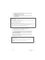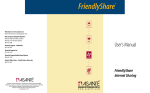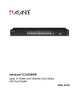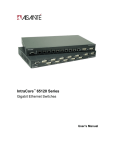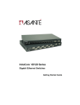
1
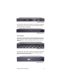
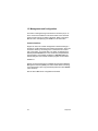
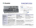
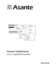
IntraCore® 35516 Series
Layer 2/3/4 Gigabit Switches
Setup Guide
2
Setup Guide
Table of Contents
1. Introduction
1.1 Features
1.2 Package Contents
1.3 LEDs
1.4 Front and Back Panel Descriptions
1.5 Management and Configuration
2. Installation and Setup
2.1 Safety Overview
2.2 Recommended Installation Tools
2.3 Power Requirements
2.4 Environmental Requirements
2.5 Cooling and Airflow
2.6 Installation Overview
2.7 Chassis Installation/Placement
2.8 Installing GBIC Interfaces
2.9 Installing Optional Emergency Power
Supply
2.10 Connecting Power
2.11 Connecting to the Network
2.12 Connecting to a Console
2.13 Configuring an IP Address
2.14 Restoring Factory Defaults
5
6
6
6
8
10
11
11
12
12
12
13
13
13
15
16
Appendix A Troubleshooting
Appendix B Safety and Regulatory Compliance
Appendix C Specifications
Appendix D Serial Port Pin Outs
Appendix E Warranty and Support
25
27
29
31
33
Asanté IntraCore 35516 Series Switches
17
17
19
21
23
3
4
Setup Guide
1 Introduction
Thank you for purchasing the Asanté IntraCore 35516 Series Gigabit switch. The IC35516 is from a family of multi-media and multiprotocol switches capable of supporting Layer 2 switching and
Layer 3 and Layer 4 protocols. They are designed to offer industryleading performance at a very competitive cost of ownership.
Each IntraCore 35516 switch is a 16-port solution for Gigabit
Ethernet switching using shared-memory architecture to achieve
Gigabit switching on all ports. The highly integrated system includes
MACs, address look-up, content addressable memory (CAM),
switch engine, primary buffer memory, and programmable quality of
service (QoS).
Two models in the IntraCore 35516 series cover different customer
applications.
The IC35516-T is a 16-port switch that has 12 10/100/1000BaseT
ports and 4 dual-function Gigabit ports that support either
1000BaseT RJ-45 Gigabit ports or GBIC Gigabit ports.
The IC35516-G is a 16-port switch that has 12 GBIC style Gigabit
Ethernet ports and 4 dual-function Gigabit ports that support either
1000BaseT RJ-45 Gigabit ports or GBIC Gigabit ports.
The following types of GBIC modules are supported on the IC
35516 switches:
•
•
•
•
•
1000SX multi-mode fiber for 500 m applications
1000LX single-mode fiber for 2 km applications
1000LH single-mode fiber for 20 km applications
1000LZ single-mode fiber for ultra distance (120 km) applications
1000BaseT copper gigabit for low-cost 100 m applications
The system can operate as a stand alone network or be used in
combination with other IntraCore switches in the backbone.
Asanté IntraCore 35516 Series Switches
5
1.1 Features
The IC35516 is a high-performance, compact switch that is also a
multi-media, multi-protocol (Ethernet, L2/L3/L4) router. The following is a partial list of the switch’s features (please refer to the User’s
Manual on the CD-ROM for a complete list of features):
•
•
•
•
•
•
•
Supports SNMP and RMON
Advanced VLSI switch engine
IEEE 802.1Q VLAN and 802.1p 8-level class of service
Layer 2,3,4 and 4 software enhancement
Sophisticated filtering
Large address table
Jumbo packet support (up to 32 KB in size)
1.2 Package Contents
The following items are included in your package:
•
•
•
•
•
•
•
Switch
AC power cord
Rack mount brackets with screws
Rubber feet
User’s Manual (on CD-ROM)
Setup Guide (this document)
IC35516 CD-ROM
Contact your dealer immediately if any of these items is missing.
Tip! For your convenience, the User's Manual is on the IC35516
CD-ROM. As an Adobe PDF document, you can search or print
specific pages. The most recent version of the User's Guide
can also be found on the Asanté website: http://www.asante.
com.
6
Setup Guide
1.3 LEDs
The system’s front panel LED display allows the manager to monitor the status of the switch. Refer to the following sections for LED
information specific to the switch’s model.
1.3.1 IC35516-T
The IC35516-T has one power LED indicator, one (optional) emergency power LED, and two LED indicators for each of the 16 ports.
See the table below for a complete LED description.
LED
Color
Description
Power
Green
Power is on.
Off
Power is off, or main power has failed.
Green
Primary power has failed and optional power supply
is powering the switch.
Off
Optional power supply is in standby mode and primary power is working.
Green
A valid 1000 Mbps link has been established.
Yellow
A valid 10/100 Mbps link has been established.
Off
No link has been established.
Blinking Green
Activity is detected in full-duplex mode.
Blinking Yellow
Activity is detected in half-duplex mode.
Off
No traffic has been detected, or no link has been
established.
Emergency
Power
Link/Speed
Duplex/Activity
1.3.2 IC35516-G
The IC35516-G has one power LED, one (optional) emergency
power LED, two LED indicators for 10/100/1000BaseT status, and
one LED for GBIC status. See the following table for a complete
LED description.
Asanté IntraCore 35516 Series Switches
7
LED
Color
Description
Power
Green
Power is on.
Off
Power is off, or main power supply has failed.
Green
Primary power has failed and optional power supply
is powering the switch.
Optional power supply is in standby mode and primary power is working.
Emergency Power
Off
BaseT
10/100/1000
Link/Speed
BaseT
10/100/1000
Duplex/Activity
GBIC
Link
Green
A valid 1000 Mbps link has been established.
Yellow
A valid 10/100 Mbps link has been established.
Off
No link has been established.
Blinking Green
Activity is detected in full-duplex mode.
Blinking Yellow
Activity is detected in half-duplex mode.
Off
No traffic has been detected, or no link has been
established.
Green
A valid 1000 Mbps link has been established.
Off
No link has been established.
1.4 Front and Back Panel Descriptions
Refer to the following sections for detailed descriptions of the front
and back panels of the IC35516 series switches.
1.4.1 IC35516-T
The front panel of the IC35516-T contains the following: power and
port LEDs; 12 10/100/1000BaseT ports; 4 dual-function Gigabit
ports that support either 1000BaseT or GBIC-style Gigabit Ethernet
ports; and a console port.
8
Setup Guide
IC35516-T Front Panel
The back panel, shown below, contains a 12 VDC jack for (optional)
emergency power; the primary power bay cover plate; the primary
power outlet; and the on/off switch.
IC35516-T Back Panel
1.4.2 IC3516-G
The front panel of the IC35516-G contains the following: power and
port LEDs; 12 GBIC ports; 4 dual-function Gigabit ports that support
either 1000BaseT or GBIC-style Gigabit Ethernet ports; and a console port.
IC35516-G Front Panel
The back panel, shown below, contains a 12 VDC jack for (optional)
emergency power; the primary power bay cover plate; the on/off
switch; and the primary power outlet.
IC35516-G Back Panel
Asanté IntraCore 35516 Series Switches
9
1.5 Management and Configuration
The switch is managed using Command Line Interface (CLI) in order to access several different command modes. Each command
mode provides a group of related commands. Refer to the User’s
Manual on the accompanying CD-ROM for more information.
Console Interface
Support for local, out-of-band management is delivered through a
terminal or modem attached to the EIA/TIA-232 interface. Users can
access the switch by connecting a PC or terminal to the console
port of the switch, via a serial cable. The switch is shipped with a
default password Asante set on the console line (the password is
case-sensitive), and a default IP address of 192.168.0.1/24. The
default settings for the terminal emulation program are as follows:
9600-8-N-1
Remote in-band management is available through Simple Network
Management Protocol (SNMP) and Telnet client. When connecting
via a Telnet session (line vty0) the default password is also Asante
(case-sensitive).
See the User’s Manual for configuration information.
10
Setup Guide
2 Installation and Setup
This chapter explains how to install and connect the switch to
the network. To configure the switch for management, refer to
the User’s Manual on the CD-ROM.
The following guidelines will help in installing the switch in such
a way that it has the proper power supply and environment.
2.1 Safety Overview
The following information provides safety guidelines to ensure
safety and to protect the switch from damage.
Note: Be aware, however, that this information is intended as a
guideline, and may not include every possible hazard to which the
user may be exposed. Use caution when installing this switch.
•
•
•
•
•
Only trained and qualified personnel should be allowed to install or replace this equipment
Always use caution when lifting heavy equipment
Keep the chassis clean
Keep tools and chassis components off the floor and away from
foot traffic
Avoid wearing rings or chains (or other jewelry) that could get
caught in the chassis. Metal objects can heat up and cause
serious injury to persons and damage to the equipment. Avoid
wearing loose clothing, such as ties or loose sleeves
When working with electricity, follow these guidelines:
•
•
•
•
Before accessing the interior of the chassis, locate
the emergency power-off switch for the room you
are in
Disconnect all external cables before installing or removing a
chassis
Do not work alone when working with electricity
Always check that the power has been disconnected from the
circuit
Asanté IntraCore 35516 Series Switches
11
•
•
Do not tamper with the internal components of the switch. This
could void the product’s warranty
Examine the work area for potential hazards (such as wet
floors or ungrounded cables) and eliminate them before installing the switch
For more safety information, please refer to the User’s Manual.
2.2 Recommended Installation Tools
The following tools and equipment (not included)
are needed to install the switch:
•
•
•
Flat head screwdriver
Phillips head screwdriver
Antistatic mat or foam
2.3 Power Requirements
The electrical outlet should be located near the switch and be easily
accessible. It must also be properly grounded.
Make sure the power source adheres to the following guidelines:
•
•
Power: Auto-switching 90-260 VAC
Frequency range: 50/60 Hz
2.4 Environmental Requirements
The switch must be installed in a clean, dry, dust-free area
with adequate air circulation to maintain the following environmental limits:
•
•
12
Operating Temperature: 0° to 40° C (32° to 104° F)
Relative Humidity: 10% to 90% non-condensing
Setup Guide
Failure to observe these limits may cause damage to the switch and
void the warranty.
Avoid direct sunlight, heat sources, or areas with high levels of
electromagnetic interference.
2.5 Cooling and Airflow
The switch uses internal fans for air cooling. Do not restrict air
flow by covering or obstructing air vents on the sides of the
switch.
2.6 Installation Overview
Follow these steps to install the switch:
1.
2.
3.
4.
5.
Open the box and check the contents. See Chapter 1.2 Package
Contents for a complete list of the items included with the switch.
Install the IntraCore switch chassis in an equipment rack or wall
rack, or prepare it for desktop placement.
Connect the power supply.
Connect network devices to the switch.
Refer to the User’s Manual for configuring the switch for management capabilities.
2.7 Chassis Installation/Placement
The switch can be installed in a standard 19-inch equipment rack. It
can also be placed on a stable horizontal surface.
Note: The equipment rack or desk on which you install the switch
must be secure and stable. Equipment racks must be fastened to
the floor; desks must be resting on a flat, stable surface.
2.7.1 Installation in an Equipment Rack
Important! Before continuing, disconnect all cables from the
switch.
Asanté IntraCore 35516 Series Switches
13
To mount the switch onto an equipment rack:
1.
2.
3.
4.
5.
6.
Place the switch on a flat, stable surface.
Locate a rack-mounting bracket (supplied) and place it over the
mounting holes on one side of the unit.
Use the screws (supplied) to secure the bracket (with a Phillips
screwdriver).
Repeat the two previous steps
on the other side of the unit.
Place the switch in the equipment rack.
Secure the switch by securing
its mounting brackets onto the
equipment rack.
Important! Make sure the unit is
supported until all of the mounting screws for each bracket are secured to the equipment rack. Failure to do so could cause the unit to
fall, which may result in personal injury or damage to the unit.
2.7.2 Equipment Rack Guidelines
•
•
•
Size:
17.1 x 10.1 x 1.6 inches (IC35516-T)
17.5 x 14.0 x 2.6 inches (IC35516-G)
Ventilation: Ensure that the rack is installed in a room in
which the temperature remains below 40° C (104° F). Be sure
that no obstructions, such as other equipment or cables,
block airflow to or from the vents.
Clearance: In addition to providing clearance for ventilation, ensure
that adequate clearance for servicing the switch from the front exists.
2.7.3 Free-Standing/Desktop Placement
The switch has rubber feet for the bottom of the case that allow for secure, free-standing placement of the unit.
Follow the steps below for free-standing/desktop placement:
1.
2.
3.
14
Attach the rubber pads (supplied) to the bottom of each corner of
the unit.
Place the unit on a flat, stable surface.
Make sure enough ventilation space between the switch and surrounding walls or objects exists.
Setup Guide
2.8 Installing GBIC Interfaces
Instructions for installing, removing, and maintaining GBIC interfaces are provided in this section.
Note: Auto-negotiation must be disabled on a port where a copper
GBIC is installed.
Important! The GBIC ports on the 35516-G are paired—
port numbers 1/2, 3/4, 5/6, 7/8, 9/11, 10/12, 13/15, and
14/16. DO NOT use more than one copper GBIC module
per pair (maximum 8 modules).
2.8.1 Installing a GBIC
Note: GBICs are hot-swappable.
This means that they can be inserted and removed while the unit
is powered on.
1.
2.
3.
4.
Remove the GBIC from its protective packaging.
Grip the sides of the GBIC with your thumb and forefinger, then
insert the GBIC into the slot on the face of the Gigabit Ethernet
module.
Slide the GBIC into the slot until you hear or feel a click. The
click indicates that the GBIC is locked into the slot.
Connect your network cable.
2.8.2 Removing a GBIC
Note: Copper GBIC modules run hot under normal operating conditions. Remove with care and place on a heat-resistant surface and
allow to cool before handling.
Follow the steps below to remove a GBIC interface from a Gigabit
Ethernet module:
1.
2.
3.
Disconnect the network cable from the GBIC connector.
Release the GBIC from the slot by simultaneously squeezing
the locking tabs on both sides of the GBIC.
Slide the GBIC out of the slot and store the GBIC in its protective packaging.
Asanté IntraCore 35516 Series Switches
15
2.8.3 GBIC Care and Handling
Follow these GBIC maintenance guidelines:
•
•
•
•
Unnecessary removal and insertion of a GBIC can lead to
its premature failure. A GBIC connector has a lifetime of
100 to 500 removals/insertions
GBICs are static-sensitive. To prevent ESD damage, follow
your normal board and component handling procedures
GBICs are dust-sensitive. When the GBIC is stored or
when a fiber-optic cable is not plugged in, always keep
plugs in the GBIC optical bores
Use an alcohol swab or Kim-Wipe to clean the ferrules of
the optical connector. The most common source of contaminants in the optical bores is debris picked up from the
optical connectors
2.9 Installing Optional Emergency Power Supply
To ensure reliability, the IC35516 can be equipped with a 12 VDC
emergency backup power supply (the IC35-EPS12, sold separately). When installed, the emergency power supply is in standby
mode, and will automatically take over should the primary unit fail.
To verify the primary system power status, use the
Router# show system
command. Under System Information, the status is listed:
Power Unit Status = OK
The IC35-EPS12 is designed to be a temporary replacement when
the primary power fails, not a permanent replacement.
To install the optional power supply, simply attach the 12VDC connector of the power supply to the jack located in the center of the
rear panel of the switch. Connect the power cord to the power supply and plug the power cord into an outlet.
Important! The optional power supply becomes HOT under normal
operating conditions. To avoid damage or injury, set the power supply on a heat-resistant surface and USE CAUTION when handling
the unit.
16
Setup Guide
2.10 Connecting Power
Important! Carefully review the power requirements (Chapter 2.3)
before connecting power to the unit.
Use the following procedure to connect power to the switch:
1.
2.
Plug one end of the supplied power cord into the power connector on the back of the unit.
Plug the other end into a grounded AC outlet. The power LED
will begin its initialization process.
The front panel LEDs blink and the power LED illuminates when it
has initialized. The switch is ready for connection to the network.
Important: If the power does not come on, refer to Appendix A
Troubleshooting.
2.11 Connecting to the Network
The switch may be connected to an Ethernet network with the unit
powered on or off. Use the following procedure to make your network connections:
1.
2.
Connect network devices to the switch, using the cable guidelines that follow.
After the unit is connected to the network, it can be configured
for management capabilities. Please refer to the User’s Manual
on the CD-ROM for instructions on how to set up the management features of the switch.
2.11.1 10/100/1000BaseTX Ports Cabling Procedures
The 10/100/1000 ports on the switch allow for the connection of
10BaseT, 100BaseTX, or 1000BaseT network devices. The ports are compatible with
IEEE 802.3 and 802.3u standards.
Important: The switch must be located
within 100 meters of its attached devices.
Asanté IntraCore 35516 Series Switches
17
Note: This switch has no uplink port. All 10/100/1000 ports on this
switch are auto-sensing MDI/MDI-X. This advanced feature means
that the 10/100/1000 ports will automatically determine whether the
device at the other end of the link is a hub, switch, or workstation,
and adjust its signals accordingly.
Although 10BaseT requires only pins 1, 2, 3, and 6, Asanté strongly
recommends cables with all 8 pins wired as shown in the following
table. Use Category 5 (or better) Unshielded Twisted Pair (UTP)
cables.
1000BaseT DOES require that all four pairs (8 wires) be connected
correctly. The following table shows the correct pairing of all eight
wires.
BR
WH/BR
GR
WH/BL
BL
WH/GR
OR
WH/OR
18
Pin Number
Pair Number & Wire Colors
1
2 White/Orange
2
2 Orange/White
3
3 White/ Green
4
1 Blue/White
5
1 White/Blue
6
3 Green/White
7
4 White/Brown
8
4 Brown/White
Setup Guide
2.11.2 GBIC Gigabit Ethernet Ports Cabling Procedures
Cabling requirements for the GBIC Gigabit Ethernet modules depend on the type of GBIC interface installed. Use the following
guidelines to determine the cabling requirements for your GBIC:
•
•
•
•
•
•
1000BaseSX GBIC: Cables with SC-type fiber connectors;
62.5-micron multimode fiber (MMF) media up to 275 meters (902 feet) long, or 50-micron MMF media up to 550
meters (1805 feet) long
1000BaseLX GBIC: Cables with SC-type fiber connectors;
10-micron singlemode fiber media up to 5 kilometers
(16,405 feet) long
1000BaseLH GBIC: Cables with SC-type fiber connectors;
10-micron singlemode fiber media up to 20 kilometers
(65,617 feet) long
1000BaseLX Long Haul GBIC: Cables with SC-type fiber
connectors; 10-micron singlemode fiber media up to 100
kilometers (328,100 feet) long
1000BaseLZ GBIC: Cables with SC-type fiber connectors;
10-micron singlemode fiber media up to 120 kilometers
(393,701 feet) long
1000BaseT: Category 5 or better UTP cable to a distance
of 100 meters (328.1 feet) long
When attaching a workstation to the device, a standard straightthrough CAT5 cable may be used, even when the workstation is
attached via a patch panel. No crossover cable is needed with the
MDX/MDI ports. It is recommended that the switch be kept off the
network until proper IP settings have been set.
2.12 Connecting to a Console
To connect the switch to a console or computer, set up the system
in the following manner:
1.
2.
3.
Plug power cord into the back of switch.
Attach a straight-through serial cable between the RS232 console port and a COM port on the PC.
Set up a HyperTerminal (or equivalent terminal program) in the
following manner:
Asanté IntraCore 35516 Series Switches
19
•
•
•
•
•
•
•
•
Open the HyperTerminal program, and from its file menu,
right-click on Properties
Under the Connect To tab, choose the appropriate COM
port (such as COM1 or COM2)
Under the Settings tab, choose VT100 for Emulation
mode
Select Terminal keys for Function, Arrow, and Ctrl keys.
Be sure the setting is for Terminal keys, NOT Windows
keys
Back under the Connect To tab, press the Configuration
button
Set the data rate to 9600 Baud
Set data format to 8 data bits, 1 stop bit and no parity
Set flow control to NONE
Now that terminal is set up correctly, power on the switch (boot sequence will display in terminal).
20
Setup Guide
After connecting to the console, a prompt like the following will appear:
User Access Verification
Password:
By default, the password assigned to the console line is Asante
(case-sensitive). Type it at the prompt and press Enter. See the
User’s Manual for instructions on how to change the password. The
default password for telnet access (vty0) is Asante (case-sensitive).
2.13 Configuring an IP Address
The switch ships with a default IP address of 192.168.0.1. Follow
the steps below to change the switch’s IP address.
1.
2.
3.
4.
Connect to the console and press Enter at the Password
prompt, as described above.
The screen will display the user mode prompt, Router>.
Type enable. The new prompt is Router#.
Type configure terminal. The new prompt is
Router(config)#.
Asanté IntraCore 35516 Series Switches
21
5.
6.
The default IP address is assigned to the veth1 interface. Type
interface veth1. The new prompt is
Router(config-if-veth1)#.
Type ip address and the new address. Your screen will look
like this example:
13:22:24 Wed Nov 20 2002: Login from console.
Router> enable
Router# configure terminal
Router(config)# interface veth1
Router(config-if-veth1)# ip address 192.168.123.254 255.255.255.0
Router(config-if-veth1)# end
Router# show interface veth1
veth1 is up, line protocol is up
Hardware is virtual interface VLAN 1, address is 00:00:94:D2:56:FA
Encapsulation ARPA, Flags:<UP,BROADCAST,RUNNING,MULTICAST>
inet 192.168.123.254/24 broadcast 192.168.123.255
ARP Type: ARPA, ARP Timeout: 14400 seconds
Router#
It is also acceptable to enter the subnet mask by typing
ip address 192.168.123.254/24.
Use the show interface veth1 command from privileged mode to
see the new IP address. The new IP address automatically writes
over the default IP address.
Enter the commands shown in the following screen in order to save
the change to the IP address.
Router(config-if-veth1)# end
Router# write file
Writing current-config to startup-config. Please wait…
Configuration saved to startup-config file
Router#
22
Setup Guide
2.14 Restoring Factory Defaults
If you ever need to restore the switch to its factory default settings,
follow the commands shown in the following screen.
Router> enable
Router# reload ?
factory-default Reset ALL system parameters to factory
default
<cr>
Router# reload factory-default
Please refer to the User’s Manual for more information on assigning
IP addresses, and on how to configure the switch for management.
Asanté IntraCore 35516 Series Switches
23
24
Setup Guide
Appendix A Basic Troubleshooting
In the unlikely event that your network does not operate properly,
follow the troubleshooting tips below:
1.
2.
3.
CHECK YOUR POWER CONNECTION. Is the Power LED on?
If not, plug the power cord into another known working AC outlet.
CHECK YOUR NETWORK CABLES. Are the LINK LEDs on? If
not, check the cable connections. Are the connectors seated
correctly in each port? Make sure that the correct type of cable
is connected to each port.
CHECK YOUR GBIC CONNECTORS. Are the cables inserted
correctly? The receiving and transmitting plugs must be inserted into their respective receptacles correctly in order to establish a link.
See the Troubleshooting section of the User’s Manual for more detailed information.
Asanté IntraCore 35516 Series Switches
25
26
Setup Guide
Appendix B Safety and Regulatory Compliance
FCC Compliance Statement
This equipment has been tested and found to comply with the limits
for a Class A digital device, pursuant to part 15 of the FCC Rules.
These limits are designed to provide reasonable protection against
harmful interference when the equipment is operated in a commercial environment. This equipment generates, uses, and can radiate
radio frequency energy and, if not installed and used in accordance
with the instruction manual, may cause harmful interference to radio
communications. Operation of this equipment in a residential area is
likely to cause harmful interference, in which case the user will be
required to correct the interference at their own expense.
Safety Advisory
1.
2.
3.
4.
This product should be operated from the type of power source
indicated on the marking label. If you are not sure of the type of
power available, consult your dealer or local power company.
Do not allow anything to rest on the power cord. Do not locate
this product where people will walk on the cord.
Never push objects of any kind into this product through cabinet slots as they may touch dangerous voltage points or short
out parts, resulting in a risk of fire or electric shock. Never spill
liquid of any kind on the product.
Do not attempt to service this product yourself, as opening or
removing covers may expose you to dangerous voltage points
or other risks. Refer all servicing to service personnel.
Asanté IntraCore 35516 Series Switches
27
28
Setup Guide
Appendix C Specifications
The IntraCore 35516 Series contains Asanté’s most powerful, flexible workgroup switches. See the User’s Manual for detailed specifications.
Physical Dimensions
IC35516-T: 17.1 x 10.1 x 1.6 inches (434 x 257 x 41 mm)
IC35516-G: 17.5 x 14.0 x 2.6 inches (445 x 356 x 66 mm)
Environmental
Operating Temperature:
Operating Humidity:
0 to 40ºC (32 to 104ºF)
10 to 90% RH
Power Supply
100-240VAC/50-60 Hz input
Safety and Emissions Certification
FCC Class A, CE , UL, cUL
Asanté IntraCore 35516 Series Switches
29
30
Setup Guide
Appendix D Serial Port Pin Outs
The console port is used to connect with a terminal using a DB-9
female connector. The setting is 9600-8-N-1. See the table below
for a list of pin outs.
Pin Number
Signal
1
CD
Carrier Detect
2
RD
Receive Data
3
TD
Transmit Data
4
DTR
5
SG
6
DSR
Data Set Ready
7
RTS
Request to Send
8
CD
Carrier Detect
9
RI
Ring Indicator
Asanté IntraCore 35516 Series Switches
Name
Data Terminal Ready
Signal Ground
31
32
Setup Guide
Appendix E Warranty and Support
The IntraCore switch is covered by Asanté’s 3-year IntraCare™
product warranty and advanced technical support. An additional 2year warranty is available through AsantéCare™. See the User’s
Manual for more detailed information.
If, after attempting the troubleshooting tips found here and in the
User’s Manual, your switch is still not operating properly, contact
Asanté Technologies, Inc. Technical Support (801-566-8991 or
www.asante.com/support).
Before contacting Technical Support, however, please register your
switch online at www.asante.com/support/registration.html, or by
returning the warranty card by mail. In doing so, you’ll be entitled to
special offers, up-to-date information, and important product bulletins.
Asanté IntraCore 35516 Series Switches
35
36
Setup Guide
Asanté IntraCore 35516 Series Switches
37
38
Setup Guide
Asanté IntraCore 35516 Series Switches
39
IntraCore 35516 Series
Setup Guide
Asanté Technologies, Inc.
821 Fox Lane
San Jose, CA 95131
USA
SALES
800-662-9686 Home/Office Solutions
800-303-9121 Enterprise Solutions
408-435-8388
TECHNICAL SUPPORT
801-566-8991 Worldwide
www.asante.com/support
Copyright © 2003 Asanté Technologies, Inc. Asanté and IntraCore are registered trademarks of Asanté Technologies, Inc. The Asanté logo, AsantéCare, and IntraCare are trademarks of Asanté Technologies, Inc. All other
names or marks are trademarks or registered trademarks of their respective owners. All features and specifications are subject to change without prior notice.
P/N 06-00680-00 Rev. A 02/12/03