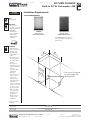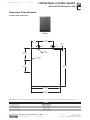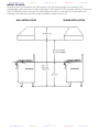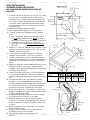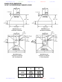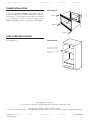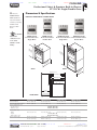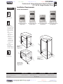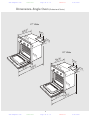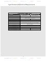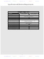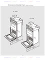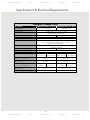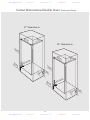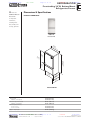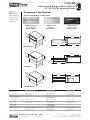
1
Dimension Express Booklet
Prepared On: 6/25/2009
.
Prepared By:
Job Information:
From:
Company:
Address:
Phone:
Fax:
Email:
Job Name: Dorini--McClelland
Tom Bogna
Classic Custom Cabinets
11544 Sheldon street
818-767-1144
818-767-1278
[email protected]
Model No
Type
VDB450
VDB450
VDB450
VCWH3648SS
VCWH3648SS
VCWH3648SS
VMOS200SS
VMOS200SS
VESO5301
VESO5301
VDSC5364Q
VDSC5364Q
VCFF136
VCFF136
DMTK301
DSH
DSH
DSH
HOD
HOD
HOD
MIC
MIC
OVN
OVN
RNG
RNG
REF
REF
TKT
Manufacturer
Doc Type
Viking
Viking
Viking
Viking
Viking
Viking
Viking
Viking
Viking
Viking
Viking
Viking
Viking
Viking
Viking
Mfr Guide
Condensed
Support Doc
Data Sheet
Mfr Guide
Condensed
Mfr Guide
Installation
Mfr Guide
Condensed
Mfr Guide
Condensed
Mfr Guide
Condensed
Mfr Guide
Page
3
5
8
9
11
16
30
33
37
39
52
53
57
60
64
Please forward to Brian.
- Thank you for using our NEW PDF Booklet Feature!! We hope this
feature will save you time when working on your project.
- Dimension Express is now offering FREE model listings for
manufacturers. All information listed with Dimension Express MUST be
approved by the manufacturer. Please check back regularly as we are
adding manufacturers and industries.
To access over 14,000 appliance specification sheets, visit:
http://www.dexpress.com
www.dexpress.com
Page 1 of 76
6/25/2009
Dimension Express Booklet
Table of Contents (continued)
Model No
Type
DMTK301
VEWD103SS
VEWD103SS
VEWD103SS
TKT
WAR
WAR
WAR
Manufacturer
Doc Type
Viking
Viking
Viking
Viking
Installation
Data Sheet
Mfr Guide
Condensed
Page
67
71
72
74
To access over 14,000 appliance specification sheets, visit:
http://www.dexpress.com
www.dexpress.com
Page 2 of 76
6/25/2009
www.dexpress.com
Please see
Mfr Guide
Page 3 of 76
VDB450
6/25/2009
KITCHEN CLEANUP
Built-In 24”W. Dishwasher 450
Dimensions & Specifications
Installation Notes &
Accessories
PRODUCT DIMENSIONS
for important
installation
information,
including panel and
handle kits.
VDB450
Professional
Built-In Dishwasher
DFB450
Custom Front
Built-In Dishwasher
See Custom Panels section for
more information and additional
specifications.
23-3/4”
(60.3 cm)
Cabinet flush
23
(60-7/8
”
.6
cm
)
23-1/8”
(59.0 cm)
Panel flush
33
(86-7/8
.0 ”
mi cm)
n
to .
3
5
(89 ”
.0
ma cm)
x.
20-1/4”
(51.4 cm)
”
24 cm)
.0
(61
49”
(124.5 cm)
Note: If the dishwasher is installed in a corner, there must be a minimum clearance of 2” (5.1 cm) from the
side wall so the door can open.
All models
Overall width
23-7/8” (60.6 cm)
Overall height (from floor)
33-7/8” (86.0 cm) min. to 35” (89.0 cm) max.
Overall depth (from rear)
To edge of side (includes door panel)
24” (61.0 cm)—includes door panel
With door open
49” (124.5 cm)
Note: This unit is NOT designed to be installed without trim. All dimensions include trim.
www.dexpress.com
Mfr Guide
Page 3 of 76
PLANNING AND DESIGN GUIDE
VIKINGRANGE.COM
•
1-888-VIKING1
VDB450
6/25/2009
REVISED 9/24/08
© 2 0 0 8 V R C — INFORMATION SUBJECT TO CHANGE
www.dexpress.com
Mfr Guide
Page 4 of 76
VDB450
6/25/2009
KITCHEN CLEANUP
Built-In 24”W. Dishwasher 450
Installation Requirements
UTILITY
REQUIREMENTS
ACCESS REQUIREMENTS
GAS
Not applicable
ELECTRICAL
• Five-foot (1.5 m),
electrical cord with 90
degree 3-prong plug
• 120V/60 Hz
• Maximum amp
usage—15.0 amps
• Water-heating
element rating—
1,400 watts
VDB450
Professional
Built-In Dishwasher
DFB450
Custom Front
Built-In Dishwasher
See Custom Panels section for
more information and additional
specifications.
PLUMBING
• 120°F (49°C) hot
water recommended;
dishwasher will,
however, perform
properly with cold
water*
• Inlet water pressure
operating range—
10 – 125 psi (0.69 –
8.62 bar)
• Five foot (1.5 m)
braided stainless steel
water line with 3/8”
(0.95 cm)
compression fitting
supplied with
dishwasher
• Seven-foot (2.13 m)
1/2” (1.3 cm) ID
“crimp-proof”
flexible drain hose
with clamp attached
to dishwasher;
connections provided
for 5/8” (1.5 cm), 3/4”
(1.9 cm), or 1” (2.5
cm) cut as required
• High loop of drain
hose required; min.
height from floor—
20” (50.8 cm)
• Check local codes
for drain air gap
requirement
”
24 cm)
.0
(61
2
(61 4”
.0
cm
)
34
(86” mi
.4 n.
c
35 to m)
”m
(89 a
.0 x.
cm
A 2” cut-out is required
for water supply and
discharge lines.
)
*Cycle times will be
extended
All models
Cutout width
Cutout height
Cutout depth
24” (61.0 cm)
34” (86.4 cm) min. to 35” (89.0 cm) max.
24” (61.0 cm)
www.dexpress.com
Mfr Guide
Page 4 of 76
PLANNING AND DESIGN GUIDE
VIKINGRANGE.COM
•
1-888-VIKING1
VDB450
6/25/2009
REVISED 9/24/08
© 2 0 0 8 V R C — INFORMATION SUBJECT TO CHANGE
www.dexpress.com
Cond Inst
Page 5 of 76
VDB450
6/25/2009
Specifications
Dimensions & Cutout Dimensions
Professional Series
26-3/8”
(67.0 cm)
23-1/8”
(59.0 cm)
26-3/8”
(67.0 cm)
23-3/4”
(60.3 cm)
2
3-7/
(60.6 c8”
m)
Built-In Dishwasher
Description
Overall width
Overall height from floor
2-5/8”
(6.7 cm)
3-3/16”
(8.1 cm)
Overall depth from rear–Professional
Overall depth from rear–Designer
33-7/
(86. 8”
Cutout width
Cutout height
0 cm)
Cutout depth
Electrical requirements
Cabinet Flush
Panel Flush
Water-heating element rating
Inlet water temperature
Designer Series
”
1/4
20- cm)
(51
.4
25-15/16”
(65.9 cm)
23-1/8”
(59.0 cm)
26”
(66.0 cm)
23-3/4”
(60.3 cm)
49”cm)
Inlet water pressure operating range
Inlet water hose
4.5
(12
2-1/4”
(5.7 cm)
2-7/8”
(7.3 cm)
Drain hose
450 Model
23-7/8” (60.6 cm)
33-7/8” (86.0 cm) min.
35” (89.0 cm) max.
To edge of side - 24” (61.0 cm) - includes door panel
With door open - 49” (124.5 cm)
To edge of side - 24” (61.0 cm) - includes door panel
With door open - 49” (124.5 cm)
24” (61.0 cm)
34” (86.4 cm) min.
35” (89.0 cm) max.
24” (61.0 cm)
15.0 amps, 120VAC/60 Hz;
5’ (1.8 m) electrical cord 3 prong plug supplied with unit
1400 watts
120˚F (49˚C) recommended;
Dishwasher will perform properly with cold water
Note: Cycle times will vary
10 to 125 psi (.69 to 8.62 bar)
5’ (1.5 m) braided stainless steel water line with 3/8” (0.95 cm) compression
fitting connected to dishwasher
7’ (2.13 m) 1/2” (1.3 cm) ID “crimp-proof” flexible drain hose
attached to dishwasher, connections provided for 5/8” (1.6 cm),
3/4” (1.9 cm) or 1” (2.5 cm), cut as required
Drain hose high loop required
Height from floor - 20” (51.0 cm) min.
Approximate shipping weight
24”
(61.0 cm)
157 lbs. (70.7 kg)
24”
(61.0 cm
)
Cabinet Flush
Panel Flush
Custom Panel
34” m
in
(86.4 c .
m)
35” ma
(89.0 c x.
m)
www.dexpress.com
23-3/4”
(60.3 cm)
23-1/8”
(59.0 cm)
Cabinet Flush
Panel Flush
Note: A 2”
(5.1 cm) cut-out is
required for
water supply and
discharge lines.
Cond Inst
4
Page 5 of 76
VDB450
6/25/2009
5
www.dexpress.com
Cond Inst
Page 6 of 76
Custom Door Panel
VDB450
6/25/2009
(Specifications)
(Installation Option)
Have the overlay panel constructed per
dimensions. The panel thickness MAY NOT
exceed 5/8” (1.6 cm) for flush installation in most
cabinets. Ensure that the design, construction,
and installation of the panel overlay and its
handle mounting is sufficient to reliably operate
in this application with a maximum panel weight
of 18 lbs. (8.2 kg.) Custom panels should not
exceed 18 lbs. (8.2 kg.)
11-17/32"
(29.3 cm)
5-7/8"
(14.9 cm)
5/8"
(1.6 cm)
5/8"
(1.6 cm)
5/8"
(1.6 cm)
Obtain four screws with the proper thread type
for the overlay material chosen. The screws
MUST BE #8 flat head, 1-3/4” long and MUST
BE stainless steel to avoid corrosion.
Use 1/4"
router bit
9-1/8"
(23.2 cm)
a
ø1/8" 4 places
(.3 cm)
To remove face panel of dishwasher remove only the
4 Phillips screws - do not remove any other fasteners.
b
If dishwasher has a metal door skin installed,
remove the four screws. DO NOT remove any
other fasteners and ensure that only the proper
screws are removed.
10"
(25.4 cm)
29-3/4"
(75.6 cm)
Carefully tighten each screw to secure the
overlay and check to ensure that the overlay is
square with the dishwasher door and cabinet
opening and that the panel doesn’t interfere
with the operation of the dishwasher.
Verify operation of the door counter balance
springs after installation of the overlay panel.
The additional weight of the overlay panel might
require an adjustment to the preload of the
counterbalance springs. If adjustment of the
springs is required, please refer to the “Counter
Balance Spring” section.
Position custom face panel on front of dishwasher.
c
22-21/32"
(57.5 cm)
23-9/32"
(59.1 cm)
NOTE: Back side of panel shown. Use caution not to drill through front of panel.
www.dexpress.com
Cond Inst
6
Page 6 of 76
VDB450
6/25/2009
Use non-marring clamps to hold custom panel in place.
Secure with #8 1-3/4”(4.5 cm) long, stainless steel flat
head screws.
7
www.dexpress.com
Cond Inst
Page 7 of 76
VDB450
6/25/2009
General Information
General Information
• Read these instructions carefully and
completely before installing the dishwasher.
The installation should be carried out by a
qualified installer, who is familiar with all
local codes and ordinances for electrical
and plumbing connections. If the
dishwasher is being installed for the first
time, most of the work has to be done
before you move it into place. If you are
replacing an old dishwasher, you must
check the old connections.
• Electrical requirements are listed in the
“Specifications” section (page 5).
NOTE: Be sure to run the drain line through
the hole to the sink compartment before
moving the dishwasher into place.
• For service convenience, a shut-off valve
(not supplied) should be installed in the
supply line in a readily accessible location
(such as beneath the sink).
• It is recommended that the dishwasher
be connected to a hot water supply. If a
cold water supply is used, cycle times will
vary.
• It is important that the water supply line and
the shut-off valve have a sufficient flow
volume. Flush the supply line prior to
connecting it to the intake line of the
dishwasher.
• Make sure the connection is sealed and not
leaking before completing the installation.
Site Preparation
NOTE: It is recommended that a thorough
site inspection be conducted PRIOR to
unpacking and moving this appliance.
• After determining where the water
supply line will connect to the
dishwasher, provide a 2” (5.1 cm) access
hole and run the line to the approximate
fill valve location. Sealing access area
once lines are in place is recommended.
• Confirm available access to adequate power.
Drain
• The access hole for the drain line should be
2” square (5.1 cm). Locate as low and as
near to the back wall as possible.
• Do not use any fittings anywhere in the drain
line that are less than 1/2” (1.3 cm) ID.
• If the drain line is going to be connected to
a food waste disposer, be sure to remove
the knockout or plug from the fitting before
connecting drain line.
• Drain connection should be a minimum of 9”
(22.9cm) from the floor. If connection is
lower, siphoning during cycle can occur.
Water Supply
WARNING
CAUTION
Plumbing connections must comply with
applicable sanitary, safety, and plumbing
codes.
The dishwasher has a factory installed
backflow preventer. Do Not add an
additional check valve.
• Water pressure for the water supply should
be a minimum of 10 to 125 psi. The
dishwasher is supplied with a 5’ (1.5 m)
braided stainless steel water line with 3/8”
(0.95 cm) compression fitting connected to
dishwasher.
• After determining where the water supply
line will connect to the dishwasher, provide
a 2” (5.1 cm) access hole and run the water
supply line to the approximate fill valve
location.
www.dexpress.com
Cond Inst
NOTE:
The end of the drain hose is
1” (2.5 cm), but is adjustable to 3/4” (1.9 cm) or
5/8” (1.6 cm). If the drain connection is smaller
than 1” (2.5 cm), the hose can be cut to fit the
connection.
8
Page 7 of 76
VDB450
6/25/2009
3. The edges of the opening mentioned in
Item (2) should, if the partition is wood,
be smooth and rounded or, if the
partition is metal, be covered with the
grommet provided for this purpose by
the manufacturer; and
4. Care should be exercised, when the
appliance is installed or removed to
reduce the likelihood of damage to the
power supply cord.
• The dishwasher comes with a 5’ (1.8 m)
electrical cord for 110-120 volts, 15/20 amp
supply. This cord should be plugged into
the 110-120 volt outlet located under the
sink.
• If the cord is not long enough or if a hard
wire installation is needed, follow the
instructions on page 10.
NOTE: Access holes should be 2” square (5.1
cm) with no sharp edges.
Electrical Connections
This appliance must be grounded. In the
event of a malfunction or breakdown,
grounding will reduce the risk of electric
shock by providing a path of least resistance
for electric current. This appliance is
equipped with a cord having an equipmentgrounding conductor and a grounding plug.
The plug must be plugged into an
appropriate outlet that is installed and
grounded in accordance with all local codes
and ordinances.
WARNING
Disconnect the electrical power supply
and place a tag at the disconnect switch
indicating that you are working on the
circuit.
WARNING
Grounding Instructions if Hardwired:
This appliance must be connected to a
grounded metal, permanent wiring system; or
an equipment grounding conductor must be
run with the circuit conductors and connected
to the equipment – grounding terminal or
lead on the appliance.
• For a cord connected undercounter
dishwasher:
1. The power supply receptacle for the
appliance should be installed in a
cabinet or on a wall adjacent to the
under counter space in which the
appliance is to be installed;
2. There should be an opening through the
partition between the compartments
mentioned in Item (1), that is large
enough for the attachment plug to pass
through.
Be sure electrical power is turned off at
circuit breaker or fuse box before
servicing or installing unit. Do not use an
extension cord for this appliance.
WARNING
Improper connection of the equipment –
grounding conductor can result in a risk
of electric shock. Check with a qualified
electrician or serviceman if you are in
doubt as to whether the appliance is
properly grounded. Do not modify the
plug provided with the appliance; if it
will not fit the outlet, have a proper
outlet installed by a qualified electrician.
9
www.dexpress.com
CUSTOM PANEL–KITCHEN CLEANUP
Mfr Sup
Page 8 of 76
VDB450
6/25/2009
Built-In 24”W. Dishwasher—450
Dimensions & Specifications
CUSTOM PANEL DIMENSIONS
DFB450
11-17/32"
(29.3 cm)
5-7/8"
(14.9 cm)
5/8"
(1.6 cm)
5/8"
(1.6 cm)
5/8"
(1.6 cm)
Use 1/4"
router bit
9-1/8"
(23.2 cm)
ø1/8" 4 places
(.3 cm)
10"
(25.4 cm)
29-3/4"
(75.6 cm)
22-21/32"
(57.5 cm)
23-9/32"
(59.1 cm)
Note: Check that the door can be opened at any angle. If it tends to fall down, you may need to adjust the door spring tension.
DFB450
22-21/32” (57.5 cm)
29-3/4” (75.6 cm)
5/8” (1.6 cm)
18 lbs. (8.2 kg)
Overall panel width
Overall panel height
Overall panel depth
Maximum panel weight
www.dexpress.com
Mfr Sup
Page 8 of 76
PLANNING AND DESIGN GUIDE
VIKINGRANGE.COM
•
1-888-VIKING1
VDB450
6/25/2009
RELEASED 9/24/08
© 2 0 0 8 V R C — INFORMATION SUBJECT TO CHANGE
www.dexpress.com
www.dexpress.com
DE Data
Page 9 of 76
VCWH3648SS
DIMENSION EXPRESS
•
This Data Sheet Includes Information On
Viking
Product Model Number (s):
Wall Hood:
VCWH3648
•
•
Dimensions (Actual Size)
•
Width:
Upper depth:
Lower depth:
Body height:
Maximum chimney height:
Minimum chimney height:
35 7/8"
12"
24"
18"
24"
12"
Fax on Demand (925) 284-3558
Adjustable Chimney
Side View
(not to scale)
•
Additional Information
•
• Units available in Stainless Steel (SS), Black (BK),
White (WH), Almond (AL), Biscuit (BT), Stone Gray
(SG), Graphite Gray (GG), Burgundy (BU), Lemonade
(LE), Mint Julep (MJ), Forest Green (FG), Viking Blue
(VB), Cobalt Blue (CB) and Eggplant (EP).
• IMPORTANT: Do NOT obstruct motor cooling vent
area.
• Always vent this product outside. DO NOT vent to an
attic, wall, garage, room or crawl space.
• The external blowers must be vented and connected
separately. Do not restrict ducting anywhere, including
roof jacks or wall louvers.
• If possible, the vent pipe should be installed in a
straight line from the rangehood through the roof,
eliminating or reducing the number of elbow joints
(elbows reduce the efficiency of the blower). If elbow
joints are necessary, they should make gradual turns.
Elbows of 90° should be avoided. Each 90° elbow is
equivalent to increasing distance by 5-10 feet. Make
gradual turns or use 45° elbows. In runs of longer than
20 feet, the duct size can be enlarged by at least 1"
after the first 10 feet to improve performance.
.
6/25/2009
24" Max
12" Min
12"
18"
6"
24"
36" max
30" min
Cooking
Surface
72" max
66" min
36"
See page 2 for additional information
Subject to change without notice. This system is designed to
be updated daily if necessary. Dimension Express is not
responsible for use of superseded, voided, or outdated data
sheets. Because of the difficulty or impracticability of determining actual damages, liability of Dimension Express shall
not exceed $50.00.
Copyright © Dimension Express, 2007.
234
• NEVER reuse Data Sheets. Data Sheets are subject to change without
notice. Dimension Express is a FREE service bureau and is updated daily,
it makes far more sense to spend the time necessary to request new Data
Sheets for each project, as opposed to the problems, time, costs, and risks
associated with reusing old Data Sheets.
www.dexpress.com
DE Data
• Call Dimension Express if you have any questions at (800) 940-2059 •
• Always refer to a current Code at a Glance or manufacturer directory •
• Data Sheet codes change on the first of each quarter at 12:01am •
BN • A234B149 • • 071804 • 132418 • 65742
Page 9 of 76
VCWH3648SS
6/25/2009
www.dexpress.com
DE Data
Page 10 of 76
VCWH3648SS
www.dexpress.com
6/25/2009
This Data Sheet Includes Information On
Viking
DIMENSION EXPRESS
•
Page 2
Fax on Demand (925) 284-3558
Product Model Number (s):
•
Wall Hood:
VCWH3648
Additional Information:
• Ventilators recommended for this unit are DIV600 (interior) or
DEV900 (exterior). Ventilators are ordered separately.
• DIV600: 600 CFM. 120VAC, 60Hz, 6.0 maximum amps. Unit requires
a round duct size of 7", this should never be reduced. Never use
flexible duct. Maximum equivalent duct length is 50 feet; for longer
duct runs, increase duct size and contact a qualified and trained
installer.
• DEV900: 900 CFM. 120VAC, 60Hz, 8.7 maximum amps. Unit requires
a minimum round duct size of 10" or equivalent, this should never be
reduced. Never use flexible duct. Maximum equivalent duct length is
50 feet; for longer duct runs, increase duct size and contact a
qualified and trained installer.
Accessories:
• WGP30 : Wall hood warming shelf panels. The bottom edge of the
warming shelf panels drop 14 1/2" below the bottom edge of the hood.
• BKS30 : Wall hood backsplash (30" high).
DEV900 Ventilator cutouts
DIV600 Ventilator cutouts
Top View
(not to scale)
Top View
(not to scale)
35 7/8"
12"
CL
Options:
• Brass or Chrome accessory rail.
35 7/8"
12"
CL
17 15/16"
120V
electrical
supply
17 15/16"
6"
6"
12"
C
L
10" Dia.
duct cutout
12"
C
L
24"
120V
electrical
supply
7" Dia.
duct cutout
24"
Subject to change without notice. This system is designed to be updated daily if necessary. Dimension Express is not responsible for use of superseded, voided, or
outdated data sheets. Because of the difficulty or impracticability of determining actual damages, liability of Dimension Express shall not exceed $50.00.
Copyright © Dimension Express, 2007.
149
• NEVER reuse Data Sheets. Data Sheets are subject to change without
notice. Dimension Express is a FREE service bureau and is updated daily,
it makes far more sense to spend the time necessary to request new Data
Sheets for each project, as opposed to the problems, time, costs, and risks
associated with reusing old Data Sheets.
www.dexpress.com
DE Data
• Call Dimension Express if you have any questions at (800) 940-2059 •
• Always refer to a current Code at a Glance or manufacturer directory •
• Data Sheet codes change on the first of each quarter at 12:01am •
BN • A234B149 • • 071804 • 132418 • 65742
Page 10 of 76
VCWH3648SS
6/25/2009
www.dexpress.com
Mfr Guide
Page 11 of 76
VCWH3648SS
6/25/2009
HEIGHT OF HOOD
The bottom of the hood should be 30” (76.2 cm) min. to 36” (91.4 cm) max. above the countertop. This
would typically result in the bottom of the hood being 66” (167.6 cm) to 72” (175.3 cm) above the floor. The bottom
of the hood should never be more than 72” (182.9 cm) above the floor or more than 36” (91.4 cm) above the
countertop. These dimensions provide for safe and efficient operation of the hood.
ISLAND INSTALLATION
WALL INSTALLATION
www.dexpress.com
Mfr Guide
3 of 76
Page 11
VCWH3648SS
6/25/2009
www.dexpress.com
Mfr Guide
Page 12 of 76
VCWH3648SS
6/25/2009
WALL HOOD DIMENSIONS
30”/36”/42” W. PROFESSIONAL CHIMNEY HOODS
www.dexpress.com
A
B
30” W.
29 7/8”
(75.9 CM)
14 15/16”
(37.9 cm)
36” W.
35 7/8”
(91.3 cm)
17 15/16”
(45.6 cm)
42” W.
41 7/8”
(106.4 cm)
20 15/16”
(53.2 cm)
Mfr Guide
15 of 76
Page 12
VCWH3648SS
6/25/2009
www.dexpress.com
Mfr Guide
Page 13 of 76
VCWH3648SS
6/25/2009
WALL HOOD DIMENSIONS
48”/54”/60”/66” W.
PROFESSIONAL CHIMNEY HOODS
www.dexpress.com
A
B
C
48” W.
47 7/8”
(121.6 cm)
23 15/16”
(60.8 cm)
18”
(45.7 cm)
54” W,
53 7/8”
(136.8 cm)
26 15/16”
(68.4 cm)
18”
(45.7 cm)
60” W.
59 7/8”
(152.1 cm)
29 15/16”
(76.0 cm)
24”
(61.0 cm)
66” W.
65 7/8”
(167.3 cm)
32 15/16”
(83.7 cm)
24”
(61.0 cm)
Mfr Guide
16 of 76
Page 13
VCWH3648SS
6/25/2009
www.dexpress.com
Mfr Guide
Page 14 of 76
VCWH3648SS
6/25/2009
INSTALLING THE WALL HOOD DUCT COVER
1. Measure from top of the canopy to ceiling and subtract 1/8” (0.3 cm) for clearance.
2. Place the duct cover top inside the duct cover base and lower until desired height is found. (To eliminate
scratches, make a mark on the duct cover top for the desired lowering point by subtracting 18” (45.7 cm) from the
total height needed.)
3. Use the retaining nuts and bolts to fasten in place.
4. Slide the duct cover in place and fasten from inside canopy using the sheet metal screws provided.
5. Note: For installations with ceilings above 9’ (22.9 cm), use optional duct extensions. See product literature for
details
Item 1
Item 3
Canopy Top
B
Max.
A
Mín.
C
Item 4
Duct Cover
Top
Item 2
Model
“A” Mín.
“B” Max
“C”
VCWH3048
12” (30.5 cm)
24” (61.0 cm)
12” (30.5 cm)
VCWH3648
12” (30.5 cm)
24” (61.0 cm)
12” (30.5 cm)
VCWH4248
12” (30.5 cm)
24” (61.0 cm)
12” (30.5 cm)
VCWH4848
12” (30.5 cm)
24” (61.0 cm)
18” (45.7 cm)
VCWH5548
12” (30.5 cm)
24” (61.0 cm)
18” (45.7 cm)
VCWH6048
12” (30.5 cm)
24” (61.0 cm)
24” (61.0 cm)
VCWH6648
12” (30.5 cm)
24” (61.0 cm)
24” (61.0 cm)
Duct Cover
Base
12”
(30.5 cm)
www.dexpress.com
Mfr Guide
5 of 76
Page 14
VCWH3648SS
6/25/2009
BASwww.dexpress.com
IC SPECIFICATIONS Mfr Guide
INTERIOR AND EXTERIOR POWER HOODS
Page 15 of 76
VCWH3648SS
6/25/2009
WALL HOODS
DESCRIPTION
RECOM.
CFM1
(int.-interior; ext.-exterior)
30” W.
36” W. *
42”W.*
48” W.
54” W.
60” W.
66” W.
300 int./600 int./900 ext./1200 ext.
300 int./600 int./900 ext./1200 ext.
600 int./900 ext./1200 ext.
1200 int./1200 ext./1500 ext.
1200 int./1200 ext./1500 ext.
1200 int./1200 ext./1500 ext.
1200 int./1200 ext./1500 ext.
NUMBER OF
HALOGEN
LIGHTS
250 WATT
HEAT LAMPS
(Sold Separately)
2
2
2
3
3
4
4
120VAC/60Hz
SPACERS
MAX. AMPS3
Center LH RH
(Interior/Exterior)
FILTERS
1
1
1
2
2
2
2
2
2
2
2
3
3
3
0
1
1
1
2
2
0
1
1
1
1
1
1
1
1
1
1
1
1
1
1
3.9/6.0/8.7/6.0
3.9/6.0/8.7/6.0
6.0/8.7/6.1
11.5/8.5/9.2
11.5/8.5/9.2
11.9/8.9/9.7
11.9/8.9/9.7
ISLAND HOODS
DESCRIPTION
RECOM.
CFM1
(int.-interior; ext.-exterior)
NUMBER OF
HALOGEN
LIGHTS
36” W.*
42”W.*
54” W.
66” W.
600 int./900 ext./1200 ext.
600 int./900 ext./1200 ext./1500 ext.
1200 int./1200 ext./1500 ext.
1200 int./1200 ext./1500 ext.
4
4
6
8
FILTERS
SPACERS
Center LH RH
4
4
6
8
2
2
2
2
2
2
2
2
2
2
2
2
120VAC/60Hz
MAX. AMPS3
(Interior/Exterior)
3.9/6.6/3.9
4.7/7.4/4.8/5.5
8.6/5.6/6.4
9.5/6.5/7.3
*1200 or 1500 CFM exterior ventilator should be used when installed over ranges/rangetops with gas grill.
MODEL NUMBER
For Use with hoods:
DIV300 (interior)
DIV600 (interior)
DIV1200 (interior)
DEV900 (exterior)
DEV1200 (exterior)
DEV1500 (exterior)
CFM1
RECOMMENDED
DUCT SIZE
300
600
1200
900
1200
1500
7” round
7” round
10” round
10” round
10” round
10” round
MAX. DUCT
RUN2 (ft.)
50
50
50
50
50
75
PROPER INSTALLATION/DUCTING IS EXTREMELY IMPORTANT TO ENSURE MAXIMUM PERFORMANCE
FROM ANY VENTILATION PRODUCT
1. •All CFMs stated are based on tests at .1 static pressure: without applying static pressure, CFM would be greatly
overstated.
2. •Duct run length is for general reference only; for longer duct runs, increase duct size and contact a qualified and
trained installer.
•Straight runs and gradual turns are best; for example, each 90o elbow is equivalent to 5-10 feet (1.52 - 3.05 cm)
of straight run.
•Never use flexible duct; it creates back pressure/air turbulence and greatly reduces performance.
•Proper performance is dependent upon proper ducting; make sure that a qualified and trained installer is used.
•Check with a qualified and trained installer or local codes for makeup air requirement, if any.
3. •Max. amp rating for hoods includes recommended ventilator kit rating; all products must be hard wired direct
with 2-wire with ground.
www.dexpress.com
Mfr Guide
2 of 76
Page 15
VCWH3648SS
6/25/2009
BASwww.dexpress.com
IC SPECIFICATIONS Cond Inst
INTERIOR AND EXTERIOR POWER HOODS
Page 16 of 76
VCWH3648SS
6/25/2009
WALL HOODS
DESCRIPTION
RECOM.
CFM1
(int.-interior; ext.-exterior)
30” W.
36” W. *
42”W.*
48” W.
54” W.
60” W.
66” W.
300 int./600 int./900 ext./1200 ext.
300 int./600 int./900 ext./1200 ext.
600 int./900 ext./1200 ext.
1200 int./1200 ext./1500 ext.
1200 int./1200 ext./1500 ext.
1200 int./1200 ext./1500 ext.
1200 int./1200 ext./1500 ext.
NUMBER OF
HALOGEN
LIGHTS
250 WATT
HEAT LAMPS
(Sold Separately)
2
2
2
3
3
4
4
120VAC/60Hz
SPACERS
MAX. AMPS3
Center LH RH
(Interior/Exterior)
FILTERS
1
1
1
2
2
2
2
2
2
2
2
3
3
3
0
1
1
1
2
2
0
1
1
1
1
1
1
1
1
1
1
1
1
1
1
3.9/6.0/8.7/6.0
3.9/6.0/8.7/6.0
6.0/8.7/6.1
11.5/8.5/9.2
11.5/8.5/9.2
11.9/8.9/9.7
11.9/8.9/9.7
ISLAND HOODS
DESCRIPTION
RECOM.
CFM1
(int.-interior; ext.-exterior)
NUMBER OF
HALOGEN
LIGHTS
36” W.*
42”W.*
54” W.
66” W.
600 int./900 ext./1200 ext.
600 int./900 ext./1200 ext./1500 ext.
1200 int./1200 ext./1500 ext.
1200 int./1200 ext./1500 ext.
4
4
6
8
FILTERS
SPACERS
Center LH RH
4
4
6
8
2
2
2
2
2
2
2
2
2
2
2
2
120VAC/60Hz
MAX. AMPS3
(Interior/Exterior)
3.9/6.6/3.9
4.7/7.4/4.8/5.5
8.6/5.6/6.4
9.5/6.5/7.3
*1200 or 1500 CFM exterior ventilator should be used when installed over ranges/rangetops with gas grill.
MODEL NUMBER
For Use with hoods:
DIV300 (interior)
DIV600 (interior)
DIV1200 (interior)
DEV900 (exterior)
DEV1200 (exterior)
DEV1500 (exterior)
CFM1
RECOMMENDED
DUCT SIZE
300
600
1200
900
1200
1500
7” round
7” round
10” round
10” round
10” round
10” round
MAX. DUCT
RUN2 (ft.)
50
50
50
50
50
75
PROPER INSTALLATION/DUCTING IS EXTREMELY IMPORTANT TO ENSURE MAXIMUM PERFORMANCE
FROM ANY VENTILATION PRODUCT
1. •All CFMs stated are based on tests at .1 static pressure: without applying static pressure, CFM would be greatly
overstated.
2. •Duct run length is for general reference only; for longer duct runs, increase duct size and contact a qualified and
trained installer.
•Straight runs and gradual turns are best; for example, each 90o elbow is equivalent to 5-10 feet (1.52 - 3.05 cm)
of straight run.
•Never use flexible duct; it creates back pressure/air turbulence and greatly reduces performance.
•Proper performance is dependent upon proper ducting; make sure that a qualified and trained installer is used.
•Check with a qualified and trained installer or local codes for makeup air requirement, if any.
3. •Max. amp rating for hoods includes recommended ventilator kit rating; all products must be hard wired direct
with 2-wire with ground.
www.dexpress.com
Cond Inst
2 of 76
Page 16
VCWH3648SS
6/25/2009
www.dexpress.com
Cond Inst
Page 17 of 76
VCWH3648SS
6/25/2009
HEIGHT OF HOOD
The bottom of the hood should be 30” (76.2 cm) min. to 36” (91.4 cm) max. above the countertop. This
would typically result in the bottom of the hood being 66” (167.6 cm) to 72” (175.3 cm) above the floor. The bottom
of the hood should never be more than 72” (182.9 cm) above the floor or more than 36” (91.4 cm) above the
countertop. These dimensions provide for safe and efficient operation of the hood.
ISLAND INSTALLATION
WALL INSTALLATION
www.dexpress.com
Cond Inst
3 of 76
Page 17
VCWH3648SS
6/25/2009
www.dexpress.com
Cond Inst
Page 18 of 76
VCWH3648SS
6/25/2009
PREPARING FOR HOOD INSTALLATION
Plan where the ductwork will be located. See pages 11-14 for rough-in dimensions. Install proper-sized duct work,
and roof or wall cap for the type of blower you are using. Recommended hood locations for the most common
installations are shown on page 2.
Adjust your measurements for various heights of ceilings, soffits, cabinets, or ranges/rangetops.
300 -or 600 CFM
Single Blower
Interior-Power
Typical Ductwork
Roof Cap
7” Round Duct
Duct Cover
or Soffit
1200 CFM
Single Blower
Interior Power Typical Ductwork
Exterior Blower
Roof Cap
10” Round Duct
900, 1200, or
1500 CFM
Exterior Power
Typical Ductwork
10” Round
Duct
Duct Cover or
Soffit
Duct Cover or
Soffit
ELECTRICAL SUPPLY
Run 120 VAC electrical power cable from service panel to installation location. See “Basic Specifications” on page 15
for the maximum amp requirements.
(BEFORE INSTALLING ISLAND HOOD CANOPY, SKIP TO PAGE 5)
Top Mounting Holes
(Soffit or duct cover)
INSTALLING HOOD CANOPY
Center the canopy and attach to wall. Secure
the hood to wall with mounting screws
provided. Make sure that the mounting screws
are driven into the framing and not just the
drywall. Use additional mounting screws (and
wall anchors if necessary) in the other holes.
NOTE: BECAUSE OF THE WEIGHT OF THE
HOOD - MAKE SURE THAT THE MOUNTING
SCREWS ARE DRIVEN INTO THE FRAMING
AND NOT JUST THE DRYWALL. IT MAY BE
NECESSARY TO DRILL ADDITIONAL HOLES
IN THE CANOPY FOR PROPER ALIGNMENT.
www.dexpress.com
Cond Inst
4 of 76
Page 18
VCWH3648SS
6/25/2009
www.dexpress.com
Cond Inst
Page 19 of 76
VCWH3648SS
6/25/2009
INSTALLING THE WALL HOOD DUCT COVER
1. Measure from top of the canopy to ceiling and subtract 1/8” (0.3 cm) for clearance.
2. Place the duct cover top inside the duct cover base and lower until desired height is found. (To eliminate
scratches, make a mark on the duct cover top for the desired lowering point by subtracting 18” (45.7 cm) from the
total height needed.)
3. Use the retaining nuts and bolts to fasten in place.
4. Slide the duct cover in place and fasten from inside canopy using the sheet metal screws provided.
5. Note: For installations with ceilings above 9’ (22.9 cm), use optional duct extensions. See product literature for
details
Item 1
Item 3
Canopy Top
B
Max.
A
Mín.
C
Item 4
Duct Cover
Top
Item 2
Model
“A” Mín.
“B” Max
“C”
VCWH3048
12” (30.5 cm)
24” (61.0 cm)
12” (30.5 cm)
VCWH3648
12” (30.5 cm)
24” (61.0 cm)
12” (30.5 cm)
VCWH4248
12” (30.5 cm)
24” (61.0 cm)
12” (30.5 cm)
VCWH4848
12” (30.5 cm)
24” (61.0 cm)
18” (45.7 cm)
VCWH5548
12” (30.5 cm)
24” (61.0 cm)
18” (45.7 cm)
VCWH6048
12” (30.5 cm)
24” (61.0 cm)
24” (61.0 cm)
VCWH6648
12” (30.5 cm)
24” (61.0 cm)
24” (61.0 cm)
Duct Cover
Base
12”
(30.5 cm)
www.dexpress.com
Cond Inst
5 of 76
Page 19
VCWH3648SS
6/25/2009
www.dexpress.com
Cond Inst
Page 20 of 76
VCWH3648SS
6/25/2009
INSTALLING THE ISLAND HOOD DUCT COVER
1. Cut hole in ceiling for 10” diameter duct.
2. Attach duct cover mounting bracket to the top of the duct cover with the nuts and screws provided.
3. Using the screws provided, mount the bracket to the ceiling. Make sure the area is able to support at least 200 lbs.
(Center duct cover with 10” diameter hole.)
4. Run duct work down to bottom edge of duct cover and secure in place. Make sure the duct does not stick down
past the cover.
5. Attach duct cover to the top of the canopy with screws provided. Additional support can be added by running
threaded rod from the ceiling to the top of the canopy at all four corners. Holes must be drilled.
6. Install blower. (See ventilation kit installation.)
Model
VCCI3608
VCCI3609
VCCI3610
VCCI4208
VCCI4209
VCCI4210
VCCI5408
VCCI5409
VCCI5410
VCCI6608
VCCI6609
VCCI6610
www.dexpress.com
Cond Inst
6 of 76
Page 20
“A”
12” (30.5
12” (30.5
12” (30.5
12” (30.5
12” (30.5
12” (30.5
18” (45.7
18” (45.7
18” (45.7
24” (61.0
24” (61.0
24” (61.0
cm)
cm)
cm)
cm)
cm)
cm)
cm)
cm)
cm)
cm)
cm)
cm)
“B”
6” (15.2 cm)
6” (15.2 cm)
6” (15.2 cm)
6” (15.2 cm)
6” (15.2 cm)
6” (15.2 cm)
9” (22.7 cm)
9” (22.7 cm)
9” (22.7 cm)
12” (30.5 cm)
12” (30.5 cm)
12” (30.5 cm)
VCWH3648SS
“C”
12” (30.5
24” (61.0
36” (91.4
12” (30.5
24” (61.0
36” (91.4
12” (30.5
24” (61.0
36” (91.4
12” (30.5
24” (61.0
36” (91.4
6/25/2009
cm)
cm)
cm)
cm)
cm)
cm)
cm)
cm)
cm)
cm)
cm)
cm)
www.dexpress.com
Cond Inst
Page 21 of 76
VCWH3648SS
6/25/2009
ROOF INSTALLATION
EXTERIOR-POWER VENTILATOR
DEV900-EXTERIOR POWER VENTILATOR KIT
(900 CFM)
1. Locate the blower on the rear slope of the roof. Place
it in a location to minimize duct run. The location
should be free of obstacles (TV leads, electrical lines,
etc.). Bear in mind, if the blower top is level with the
roof peak, it will not be seen from the street. Keep
this approximate location in mind as you work from
within the attic.
2. Mark a point halfway between rafters.
3. Drill a guide hole through the roof at this point.
4. From the outside, use the guide hole as a starting
point.
A. Use a T-square to measure 8 1/2” (21.6 cm) to the
left of the guide hole, then down 10 3/8” (26.4 cm)
to locate the bottom left corner of the layout.
B. Mark the rectangular cutout and remove only the
shingles in this area.
5. Mark an 11” (27.9 cm) diameter circle centered on the
guide hole and mark the center of the 1 1/4” (3.2 cm)
diameter electrical wiring hole.
6. Cut out the roof board(s) along the 11” (27.9 cm)
diameter circle and drill a 1 1/4” hole as marked.
7. For flat roof installation, build a curb that will mount
the blower at a minimum pitch of 2/12. Discard end
of the blower should be pointed away from prevailing
winds.
8. Remove roofing nails from the upper two-thirds of the
shingles around the cutout area. Carefully lift the
shingles to allow the back flashing sheet on the
blower housing to fit under them.
9. Center the blower ring in the 11” (27.9 cm) diameter
hole, making sure that the 1 1/4” (3.2 cm) diameter
electrical wiring hold aligns with the hole in the wiring
box.
10. Attach the blower to the roof with the six screws
provided. It is recommended that the screws be
located inside the blower housing. All six holes in the
back panel must be filled, or any moisture that may
get inside the housing could leak into the house.
11. Using a good grade of roofing cement, seal all of the
shingles around the housing and flashing sheet as well
as the mounting screw heads.
12. Bring electrical wiring through the hole in the wiring
box and secure it according to local codes.
13. Make the electrical connections with the proper
connector for the type of wiring being used. Connect
white to white, black to black, and green or bare wire
to green.
14. Replace wiring box cover and screws. Do not pinch
wiring under the cover.
15. Check for free movement of the damper before
installing housing cover and screws.
16. Turn on power and check operation of the blower.
www.dexpress.com
Cond Inst
10 of 76
Page 21
28 1/4”
(71.8 cm)
6 3/4”
(17.1 cm)
VCWH3648SS
6/25/2009
www.dexpress.com
Cond Inst
Page 22 of 76
VCWH3648SS
6/25/2009
WALL INSTALLATION
EXTERIOR-POWER VENTILATOR
DEV900-EXTERIOR POWER VENTILATOR KIT
(900 CFM)
1. Choose a position on the outside wall. Min. 24”
(61.0cm) from ground may vary depending on local
codes or location. Make sure no wall studs, pipes or
wires run through the opening area
2. Drill a guide hole at the center of the opening area.
3. From the outside, use the guide hole as a starting
point.
A. Use a T-square to measure 10 3/4” (27.3 cm) to
the left of the guide hole, then down 12 7/8”
(32.7cm) to locate the top left corner of the
layout.
B. Starting from the top left corner, mark a 25” (63.5
cm) by 28 1/2” (72.4 cm) rectangle on the wall
located from guide hole.
4. Cut a rectangular hole in the siding only. Do not cut
the sheathing. Nail down all siding edges.
5. Mark an 11” (27.9 cm) diameter circle centered on
the guide hole and mark the center of the 1 1/4” (3.2
cm) diameter electrical wiring hole.
6. Cut the 11” (27.9 cm) hole in the sheathing and drill
the 1 1/4” (3.2 cm) as marked.
7. Place a large bead of caulk on the back side of the
housing along the outer edge
8. Center the blower ring in the 11” (27.9 cm) diameter
hole, making sure that the 1 1/4” (3.2 cm)
diameter electrical wiring hold aligns with the
hole in the wiring box.
9. Attach the blower to the roof with the six
screws provided. It is recommended that the
screws be located inside the blower housing.
All six holes in the back panel must be filled, or
any moisture that may get inside the housing
could leak into the house.
10. Using a good grade of roofing cement, seal all
the mounting screws.
11. Bring electrical wiring through the hole in the
wiring box and secure it according to local
codes.
12. Make the electrical connections with the proper
connector for the type of wiring being used.
Connect white to white, black to black, and
green or bare wire to green.
13. Replace wiring box cover and screws. Do not
pinch wiring under the cover.
14. Check for free movement of the damper before
installing housing cover and screws.
15. Turn on power and check operation of the blower.
16. Top and side flanges of the back plate may be
covered with trim strips. Do not block grill opening
at bottom with trim. It will adversely affect
performance of the blower.
www.dexpress.com
Cond Inst
11 of 76
Page 22
Black
to
Black
Green to
Green
120 VAC
Line in
White
to
White
VCWH3648SS
6/25/2009
www.dexpress.com
Cond Inst
Page 23 of 76
VCWH3648SS
6/25/2009
ROOF INSTALLATION
EXTERIOR-POWER VENTILATOR
DEV900-EXTERIOR POWER VENTILATOR KIT
(900 CFM)
1. Locate the blower on the rear slope of the roof. Place
it in a location to minimize duct run. The location
should be free of obstacles (TV leads, electrical lines,
etc.). Bear in mind, if the blower top is level with the
roof peak, it will not be seen from the street. Keep
this approximate location in mind as you work from
within the attic.
2. Mark a point halfway between rafters.
3. Drill a guide hole through the roof at this point.
4. From the outside, use the guide hole as a starting
point.
A. Use a T-square to measure 9 13/16” (24.9 cm) to
the left of the guide hole, then down 12 11/16”
(32.2 cm) to locate the top left corner of the layout.
B. Starting from the top left corner, mark the
rectangular cutout and remove only the shingles in
this area.
28 1/4”
(71.8 cm)
5. Mark an 11” (27.9 cm) diameter circle centered on the
guide hole and mark the center of the 1 1/4” (3.2 cm)
diameter electrical wiring hole.
6. Cut out the roof board(s) along the 11” (27.9 cm)
diameter circle and drill a 1 1/4” hole as marked.
6 3/4”
7. For flat roof installation, build a curb that will mount
(17.1 cm)
the blower at a minimum pitch of 2/12. Discard end of
the blower should be pointed away from prevailing
winds.
8. Remove roofing nails from the upper two-thirds of the
shingles around the cutout area. Carefully lift the
shingles to allow the back flashing sheet on the blower
housing to fit under them.
A
B
C
D
9. Center the blower ring in the 11” (27.9 cm) diameter
DEV1200
18”
15”
9 13/16”
22”
hole, making sure that the 1 1/4” (3.2 cm) diameter
(45.7 cm)
(38.1 cm)
(24.9 cm)
(55.9 cm)
21”
18”
12 5/8”
25”
electrical wiring hold aligns with the hole in the wiring DEV1500
(
5
3
.
3
c
m
)
(
4
5
.
7
c
m
)
(
3
2
.
1
c
m
)
(63.5 cm)
box.
10. Attach the blower to the roof with the six screws
provided. It is recommended that the screws be
located inside the blower housing. All six holes in the
back panel must be filled, or any moisture that may
get inside the housing could leak into the house.
Ground to
11. Using a good grade of roofing cement, seal all of the
grounding screw
shingles around the housing and flashing sheet as well
Black to
Black
as the mounting screw heads.
12. Bring electrical wiring through the hole in the wiring
box and secure it according to local codes.
13. Make the electrical connections with the proper
connector for the type of wiring being used. Connect
white to white, black to black, and green or bare wire
120 VAC
to green.
Line in
14. Replace wiring box cover and screws. Do not pinch
wiring under the cover.
15. Check for free movement of the damper before
White to
installing housing cover and screws.
Blue
16. www.dexpress.com
Turn on power and check Cond
operation
Instof the
Page 12
23 of 76
VCWH3648SS
6/25/2009
blower.
www.dexpress.com
Cond Inst
Page 24 of 76
WALL INSTALLATION
EXTERIOR-POWER VENTILATOR
VCWH3648SS
WALL CUTOUTT
6/25/2009
B
EXTERIOR POWER VENTILATOR KIT
1. Choose a position on the outside wall. Min. 24” (61.0cm)
from ground may vary depending on local codes or
14 11/16”
location. Make sure no wall studs, pipes or wires run
(37.3 cm)
through the opening area
2. Drill a guide hole at the center of the opening area.
3. From the outside, use the guide hole as a starting point.
A. Use a T-square to measure 11 13/16” (30.0 cm) to
the left of the guide hole, then down 14 11/16”
(37.3cm) to locate the top left corner of the layout.
B. Starting from the top left corner, mark a 22” (55.9
cm) by 29 1/2” (74.9 cm) rectangle on the wall
located from guide hole.
C
4. Cut a rectangular hole in the siding only. Do not cut
the sheathing. Nail down all siding edges.
5. Mark an 11” (27.9 cm) diameter circle centered on the
guide hole and mark the center of the 1 1/4” (3.2 cm)
diameter electrical wiring hole.
6. Cut the 11” (27.9 cm) hole in the sheathing and drill the
DEV1200
1 1/4” (3.2 cm) as marked.
DEV1500
7. Place a large bead of caulk on the back side of the
housing along the outer edge
8. Center the blower ring in the 11” (27.9 cm) diameter
hole, making sure that the 1 1/4” (3.2 cm) diameter
electrical wiring hold aligns with the hole in the wiring box.
9. Attach the blower to the roof with the six screws provided.
It is recommended that the screws be located inside the
blower housing. All six holes in the back panel must be
Ground to
filled, or any moisture that may get inside the housing could
grounding
leak into the house.
screw
10. Using a good grade of roofing cement, seal all the mounting
screws.
11. Bring electrical wiring through the hole in the wiring box
and secure it according to local codes.
12. Make the electrical connections with the proper connector
for the type of wiring being used. Connect white to white,
black to black, and green or bare wire to green.
13. Replace wiring box cover and screws. Do not pinch wiring
under the cover.
14. Check for free movement of the damper before installing
housing cover and screws.
15. Turn on power and check operation of the blower.
16. Top and side flanges of the back plate may be
Filter
covered with trim strips. Do not block grill opening
Spacer
at bottom with trim. It will adversely affect
performance of the blower.
3”
(7.6 cm)
29 1/2”
(74.9 cm
11”
(27.9 cm)
dia. hole
A
A
22”
(55.9 cm)
25”
(63.5 cm)
B
17”
(43.2 cm)
20”
(50.8 cm)
C
11 13/16”
(30.0 cm)
14 5/8”
(37.2 cm)
Black to
Black
120 VAC
Line in
White to
Blue
FILTER/SPACER INSTALLATION
1. Install spacer/s in center or outside of filters.
2. Number of spacers and baffle filters will vary
by model.
Baffle filter
www.dexpress.com
Cond Inst
13 of 76
Page 24
VCWH3648SS
6/25/2009
www.dexpress.com
Cond Inst
Page 25 of 76
VCWH3648SS
6/25/2009
EXTERIOR VENTILATOR DIMENSIONS
DEV1200
DEV1500
DEV900
10” (25.4 cm) diameter
Opening for wiring
A
20 3/4” (52.7 cm)
29 1/2”
(74.9 cm)
28 1/4”
(71.8 cm)
10 1/8”
(25.7 cm)
24 1/2”
(62.2 cm)
15 1/2”
(39.4 cm)
22 1/8”
(56.2 cm)
10” (25.4 cm)
diameter
B
14”
(35.6 cm)
4 3/4”
(12.1 cm)
Flashing
24 3/4”
(62.9 cm)
Flashing
DEV1200
DEV1500
A
18”
(45.7 cm)
21”
(53.3 cm)
B
22”
(55.9 cm)
25”
(63.5 cm)
WIRING DIAGRAM
EXTERIOR VENTILATOR
www.dexpress.com
Cond Inst
14 of 76
Page 25
VCWH3648SS
6/25/2009
www.dexpress.com
Cond Inst
Page 26 of 76
VCWH3648SS
6/25/2009
WALL HOOD DIMENSIONS
30”/36”/42” W. PROFESSIONAL CHIMNEY HOODS
7 1/2”
(19.1 cm)
8”
(20.3 cm)
www.dexpress.com
A
B
30” W.
29 7/8”
(75.9 cm)
14 15/16”
(37.9 cm)
36” W.
35 7/8”
(91.3 cm)
17 15/16”
(45.6 cm)
42” W.
41 7/8”
(106.4 cm)
20 15/16”
(53.2 cm)
Cond Inst
15 of 76
Page 26
VCWH3648SS
6/25/2009
www.dexpress.com
Cond Inst
Page 27 of 76
VCWH3648SS
6/25/2009
WALL HOOD DIMENSIONS
48”/54”/60”/66” W.
PROFESSIONAL CHIMNEY HOODS
www.dexpress.com
A
B
C
48” W.
47 7/8”
(121.6 cm)
23 15/16”
(60.8 cm)
18”
(45.7 cm)
54” W,
53 7/8”
(136.8 cm)
26 15/16”
(68.4 cm)
18”
(45.7 cm)
60” W.
59 7/8”
(152.1 cm)
29 15/16”
(76.0 cm)
24”
(61.0 cm)
66” W.
65 7/8”
(167.3 cm)
32 15/16”
(83.7 cm)
24”
(61.0 cm)
Cond Inst
16 of 76
Page 27
VCWH3648SS
6/25/2009
www.dexpress.com
Cond Inst
Page 28 of 76
VCWH3648SS
6/25/2009
ISLAND HOOD DIMENSIONS
36”/42” W. PROFESSIONAL CHIMNEY HOODS
900 CFM External
Ventilation Installation
600 CFM Internal
Ventilation Installation
8”
(20.3 cm)
900 CFM External
Ventilation Installation
(10” Duct Required)
www.dexpress.com
600 CFM Internal
Ventilation Installation
(7” Duct Required)
A
B
36” W.
35 7/8”
(91.3 cm)
17 15/16”
(45.6 cm)
42” W.
41 7/8”
(106.4 cm)
20 15/16”
(53.2 cm)
Cond Inst
17 of 76
Page 28
VCWH3648SS
6/25/2009
www.dexpress.com
Cond Inst
Page 29 of 76
VCWH3648SS
6/25/2009
ISLAND HOOD DIMENSIONS
54”/66” W.
PROFESSIONAL CHIMNEY HOODS
www.dexpress.com
A
B
C
54” W
53 7/8”
(136.8 cm)
26 15/16”
(68.4 cm)
18”
(45.7 cm)
66” W
65 7/8”
(167.3 cm)
32 15/16”
(83.7 cm)
24”
(61.0 cm)
Cond Inst
18 of 76
Page 29
VCWH3648SS
6/25/2009
www.dexpress.com
Mfr Guide
Page 30 of 76
VMOS200SS
6/25/2009
COOKING
Professional & Designer Microwave Oven
!
Dimensions & Specifications
Please see
Installation Notes
PRODUCT DIMENSIONS
and Accessories for
important information,
including trim kits and
multi-use chambers.
VMOS200
Professional
Microwave Oven
VMOS200
w/Trim Kit
13
(33-3/8
.9 ”
cm
)
DMOS200
Designer
Microwave Oven
DMOS200
w/Trim Kit
1
(333-3/8
.9 ”
cm
)
(6024 ”
.9
cm
)
/4” )
1
19.9 cm
(48
PROFESSIONAL
(6024”
.9
c
m)
4”
-1/cm)
9
1 .9
(48
DESIGNER
All models
24” (60.9 cm)
13-3/8” (33.9 cm)
19-1/4” (48.9 cm)
Overall width
Overall height (from bottom)
Overall depth (from rear)
Interior (each oven)
Width
Height
Depth
Approx. ship weight
17-3/8” (44.1 cm)
10-1/2” (26.6 cm)
18-5/8” (47.3 cm)
55 lbs. (24.7 kg)
www.dexpress.com
Mfr Guide
Page 30 of 76
PLANNING AND DESIGN GUIDE
VIKINGRANGE.COM
•
1-888-VIKING1
VMOS200SS
6/25/2009
RELEASED 6/10/08
© 2 0 0 7 V R C — I N F O R M AT I O N S U B J E C T T O C H A N G E
www.dexpress.com
Mfr Guide
Page 31 of 76
COOKING
VMOS200SS
6/25/2009
Professional & Designer Microwave Oven
UTILITY
REQUIREMENTS
GAS
• Not applicable
Installation Requirements
ACCESS REQUIREMENTS
VMOS200
Professional
Microwave Oven
VMOS200
w/Trim Kit
ELECTRICAL
• Three-and-a-half
foot power cord
included
• 120 VAC/60 Hz
• Maximum amp
usage—
o VMOS—
13 (1.5 kW)
o DMOS—
13 (1.5 kW)
PLUMBING
Not applicable
(4216-3
.5 /4
cm ”
t o ) mi n
.
(43 17
.2 ”
cm
)m
ax
.
t
tle
Ouation
lo c a
are
(6124-3
.9 /8
cm ”
24 to ) min
.
(62 -11
.7 /1
cm 6”
)m
ax
.
DMOS200
Designer
Microwave Oven
DMOS200
w/Trim Kit
(15 6”
.2
cm
)
(10 4”
.2
cm
)
” n.
20 ) m i
( 50
.8
cm
(10 4”
.2
cm
)
All Models
24-3/8” (61.9 cm) min. to 24-11/16” (62.7 cm) max.
16-3/4” (42.5 cm) min. to 17” (43.2) max.
20” (50.8 cm)
Cutout width
Cutout height
Cutout depth
www.dexpress.com
Mfr Guide
Page 31 of 76
PLANNING AND DESIGN GUIDE
VIKINGRANGE.COM
•
1-888-VIKING1
VMOS200SS
6/25/2009
RELEASED 6/10/08
© 2 0 0 7 V R C — I N F O R M AT I O N S U B J E C T T O C H A N G E
www.dexpress.com
Mfr Guide
Page 32 of 76
COOKING
VMOS200SS
6/25/2009
Professional & Designer Microwave Oven
! Installation Notes & Accessories
Built-In Trim Kits
•
•
•
•
Stainless Steel (SS)
Designed to match with corresponding ovens and warming drawers
Trim gives finished look to ovens installed as built-in units
Kit includes frame assemblies, exhaust duct assembly, and metal fasteners
Model
Description
VMTK271
VMTK301
VMTK361
DMTK271
DMTK301
27”W./18-1/4”H.
30”W./18-1/4”H.
36”W./18-1/4”H.
27”W./18-1/4”H.
30”W./18-1/4”H.
Approx. ship wt. lbs. (kg)
Professional microwave trim
Professional microwave trim
Professional microwave trim
Designer microwave trim
Designer microwave trim
12.9 (5.8)
13.9 (6.3)
14.9 (6.8)
14 (6.5)
15 (6.9)
Compliance Information
WARRANTY INFORMATION*
• One-year full warranty—complete product
• Five-year limited warranty—magnetron tube
• Ninety-day limited warranty—cosmetic parts such as glass, painted, and decorative items
*For complete warranty see Use & Care Guide. Warranty valid on Viking products shipped within the United States and Canada.
www.dexpress.com
Mfr Guide
Page 32 of 76
PLANNING AND DESIGN GUIDE
VIKINGRANGE.COM
•
1-888-VIKING1
VMOS200SS
6/25/2009
RELEASED 6/10/08
© 2 0 0 7 V R C — I N F O R M AT I O N S U B J E C T T O C H A N G E
www.dexpress.com
Mfr Inst
Page 33 of 76
INSTALLATION
INSTRUCTIONS
VMOS200SS
6/25/2009
VIKING RANGE CORPORATION
111 Front Street
Greenwood, Mississippi 38930 USA
(662) 455-1200
PROFESSIONAL SERIES
MICROWAVE BUILT-IN TRIM KIT
Retain for Future Reference
IMPORTANT - PLEASE READ AND FOLLOW
• Before beginning, please read these instructions completely and carefully.
• Be sure to DISCONNECT THE PLUG of the microwave oven from the electrical outlet before installing the built-in trim kit. Remove the turntable from the oven cavity.
• Because the kit includes metal parts, caution should be used in handling and installation to avoid the possibility of injury.
• Do not remove permanently affixed labels, warnings, or plates from the product. This may void the warranty.
• Please observe all local and national codes and ordinances. • The installer should leave these instructions with the consumer who should retain for local inspector’s use and for future
reference.
THIS BUILT-IN KIT IS DESIGNED FOR USE ONLY WITH VIKING MICROWAVE OVENS SPECIFYING BUILT-IN KIT
VMTK270/271, VMTK300/301, OR VMTK360/361 ON THE RATING LABEL ON THE LEFT SIDE WALL OF THE OVEN
CAVITY.
IF YOUR LOWER CONVENTIONAL OVEN IS NOT LISTED IN THE USE AND CARE MANUAL OF THE MICROWAVE
OVEN, THEN DO NOT INSTALL THE MICROWAVE OVEN ABOVE IT OR IN ANY AREA WHERE HEAT AND STEAM
ARE GENERATED; FOR EXAMPLE, NEXT TO OR ABOVE A CONVENTIONAL RANGE.
PARTS INCLUDED IN THE VMTK KIT
1) Front Frame Assembly
QTY 1
www.dexpress.com
2) Bottom Duct Assembly
QTY 1
Mfr Inst
3) Screw A (1-3/16" length)
QTY 2
Page 33 of 76
VMOS200SS
4) Screw B (1 3/4" length)
QTY 4
6/25/2009
www.dexpress.com
Mfr Inst
Page 34 of 76
VMOS200SS
6/25/2009
BASIC SPECIFICATIONS
Microwave Oven
VMOS200
Built-In Trim Kits
VMTK270/271
VMTK300/301
VMTK360/361
29-1/2” (74.9 cm)
35-1/4” (89.5 cm)
Overall Width
24”
(60.9 cm)
26-1/2” (67.3 cm)
Overall Height from
Bottom
13-3/8”
(33.9 cm)
18-1/4”
17-13/16” 18-1/4”
17-13/16” 18-1/4”
17-13/16”
(46.3 cm) (45.3 cm) (46.3 cm) (45.3 cm) (46.3 cm) (45.3 cm)
Overall Depth from
Rear
19-1/4”
(48.9 cm)
N/A
Oven Interior
Width
Height
Depth
Overall
17-3/8”
10-1/2”
18-5/8”
2.0 cu. ft.
Cutout Width
(44.1 cm)
(26.6 cm)
(47.3 cm)
N/A
N/A
Cutout Height
N/A
Cutout Depth
N/A
Min.
24-3/8”
(61.9 cm)
Max.
24-11/16”
(62.7 cm)
Min.
16-3/4”
(42.5 cm)
Max.
17”
(43.2 cm)
Min. 20”
(50.8 cm)
Electrical
Requirements
120VAC/60 Hz
N/A
Max. Amp Usage
1.5 KW
N/A
13.0 amps
Approx. Shipping Wt. 46 lbs.
(20.9 kg)
www.dexpress.com
Mfr Inst
12.9 lbs.
(5.8 kg)
Page 34 of 76
13.9 lbs.
(6.3 kg)
VMOS200SS
14.9 lbs.
(6.8 kg)
6/25/2009
www.dexpress.com
Mfr Inst
Page 35 of 76
CABINET OR WALL CUTOUT
Width (B)
Depth (C)
6/25/2009
Illustration 1
Cutout Dimensions
Height (A)
VMOS200SS
Minimum
16 3/4"
(42.5 cm)
Maximum
17"
(43.2 cm)
Minimum
24 3/8"
(61.9 cm)
Maximum
24 11/16" (62.7 cm)
Minimum
20"
4"(10.
2 cm)
6"(15.
2 cm)
A
(50.8 cm)
4"(1
0. 2 c
m)
ELECTRICAL OUTLET LOCATION
NOTE 1: If the Depth (C) dimension is greater than 21"
(53.3 cm), the outlet location may be in any area on the
rear wall.
C
B
Outlet should NOT be in the shaded area as indicated
on Illustration 1.
Illustration 2
NOTE 2: The floor of the opening should be constructed
of plywood strong enough to support the weight of the
oven and floor load (approximately 100 pounds). The
floor should be level for proper operation of the oven.
Be sure to check the local building code as it may require
that the opening be enclosed with side, ceiling and rear
partition. The proper functioning of the oven does not
require the enclosure.
FLANGES
SCREW A
BOTTOM DUCT
ASSEMBLY
SCREW A
DETAIL A
BOTTOM DUCT ASSEMBLY
1. Place the Bottom duct in the opening. When the Bottom
Duct Assembly is in the opening correctly, the flanges
will be tightly against the lower edge of the opening.
See Illustration 2.
Illustration 3
2. Secure the Bottom Duct Assembly with the two (1-3/16")
screws A. IMPORTANT: Secure screws in outer hole.
CABINET INSTALLATION
Illustration 4
1. Place the oven adjacent to the wall or cabinet opening.
Plug the power cord into the electrical outlet.
2. Carefully guide the assembled oven into the prepared
opening. Slide the oven on the Bottom Duct Assembly.
See Illustration 3. Avoid pinching the cord between the
oven and the wall. Adjust the position of the oven so
that the feet of the oven are fitted into the recesses of
the Bottom Duct Assembly. See Illustration 4.
FOOT
BOTTOM DUCT
ASSEMBLY
DUCT RECESS
www.dexpress.com
Mfr Inst
Page 35 of 76
VMOS200SS
6/25/2009
www.dexpress.com
Mfr Inst
Page 36 of 76
FRAME INSTALLATION
VMOS200SS
6/25/2009
Illustration 5
Position the FRAME ASSEMBLY to be square with the
oven. Carefully place the FRAME ASSEMBLY on the oven.
Check that it is level and then secure with two SCREWS
B. See Illustration 5. Secure the bottom portion of the
FRAME ASSEMBLY with the two remaining SCREWS B.
SCREW B
SCREW B
SCREW B
SCREW B
OVER OVEN INSTALLATION
Illustration 6
See Illustration 6.
2" (5.1 cm) For 27" W
and 30" W lower oven
4" (10.2 cm) For 36" W
lower oven
Viking Range Corporation
111 Front Street • Greenwood, Mississippi (MS) 38930 USA • (662) 455-1200
Specifications subject to change without notice.
For more product information, call 1-888-VIKING1 (845-4641), or visit our web site at http://www.vikingrange.com
F20196C
www.dexpress.com
TINSEB453MRR0
Mfr Inst
Page 36 of 76
VMOS200SS
(PS0506VR)
6/25/2009
www.dexpress.com
Mfr Guide
COOKING
Page 37 of 76
VESO5301
6/25/2009
Professional Select & Premiere Built-In Electric
27”/30”W. Single/Double Oven
!
Dimensions & Specifications
Please see
Installation Notes
PRODUCT DIMENSIONS & DOOR SWING
and Accessories for
important installation
information, including
TruGlide™ Full
Extension Oven
Racks.
ALL MODELS
Star-K Kosher
certification for use
VESO127/130
Professional Select
Single Oven
VEDO127/130
Professional Select
Double Oven
VESO5271/5301
VEDO5271/5301
Professional Premiere Professional Premiere
Single Oven
Double Oven
on the Jewish
Sabbath or Jewish
holidays
A
A
28
(73-3/4
.0 ”
cm
)
51
(13 -1/4
0.2 ”
cm
)
”
16
-9/ m)
254.9 c
(6
VESO
VEDO
45-3/4” (116.2 cm)
””
16
-9/ cm)
5
2 4.9
(6
27-1/4” (68.9 cm)
25-9/16” (64.9 cm)
23-5/8” (60.0 cm)
20-1/2”
(52.1 cm)
VESO/VEDO
Overall width (A)
Overall height (from bottom)
Overall depth (from rear)
To edge of door
With door open
Interior (each oven)
Width
Height
Depth (upper oven)
Approx. ship weight
VESO127/5271
VEDO127/5271
VESO130/5301
VEDO130/5301
26-1/2” (67.3 cm)
28-3/4” (73.0 cm)
26-1/2” (67.3 cm)
51-1/4” (130.2 cm)
29-1/2” (74.9 cm)
28-3/4” (73.0 cm)
29-1/2” (74.9 cm)
51-1/4” (130.2 cm)
25-9/16” (64.9 cm)
45-3/4” (116.2 cm)
22-5/16” (56.7 cm)
22-5/16” (56.7 cm)
25-5/16” (64.3 cm)
25-5/16” (64.3 cm)
258 lbs. (117.6 kg)/
273 lbs. (123.8 kg)
16-1/2” (41.9 cm)
16-13/16” (42.7 cm)
384 lbs. (174.2 kg)/
278 lbs. (126.1 kg)/
409 lbs. (185.5 kg)
293 lbs. (132.9 kg)
424 lbs. (192.3kg)/
449 lbs. (203.7 kg)
www.dexpress.com
Mfr Guide
Page 37 of 76
PLANNING AND DESIGN GUIDE
VIKINGRANGE.COM
•
1-888-VIKING1
VESO5301
6/25/2009
RELEASED 6/10/08
© 2 0 0 7 V R C — I N F O R M AT I O N S U B J E C T T O C H A N G E
www.dexpress.com
Mfr Guide
VESO5301
6/25/2009
COOKING
Page 38 of 76
Professional Select & Premiere Built-In Electric
27”/30”W. Single/Double Oven
Installation Requirements
UTILITY
REQUIREMENTS
ACCESS REQUIREMENTS
GAS
• Not applicable
VESO127/130
Professional Select
Single Oven
ELECTRICAL
• Five-foot flexible
steel conduit included. Equipped with
No.10 ground wire
in unit. Fuse separately.
o Four-wire with
ground
o 240 – 208/120
V/60 Hz
o Required electrical
connection
• Singles—30
• Doubles—50
o 50-amp electrical
connection for
doubles
• Max. amp usage—
(240V/208V)
o Single—24.0/20.8
o Double—40.0/34.7
A
28
(71–1/
.4 8”
c
m)
VESO5271/5301
VEDO5271/5301
Professional Premiere Professional Premiere
Single Oven
Double Oven
”
24cm)
.0
( 61
alls
e w lar
surndicu
ke
Maperpe
e
r
a
(4317”
.2
cm
VEDO127/130
Professional Select
Double Oven
A
.0
)
Ju
nc
ti o
LoBox n
ca
tio
n
Professional
Built-in
Single Oven
(12 5
.7 ”
cm
)
4
0 ”
(1
.2
cm
5
mi
n.
)
–
(10
28 5/8
.6 ”
cm
)
15
( –
m 38.71/4
in.
28
(71–1
.4 /8”
c
m)
PLUMBING
Not applicable
24c”m)
(61
24c”m)
A
e
sur
ke
Maalls areular
w ndic
e
p
per
.
(61
Professional
Undercounter
Single Oven
Cutout width (A)
Cutout height (from bottom)
Cutout depth
”
to cm)
flo
or
0
Ju
nc
tio
LoBox n
ca
tio
n
Ju
nc
tio
LoBox n
ca
tio
n
(104”
.2
cm
)
(1 2 5
.7 ”
cm
)
mi
Professional
Built-in
Double Oven
(1 2 5 ”
.7
cm
)m
in.
(104”
.2
cm
)
n.
4
(12–3/
.1 4”
cm
)
VESO127/5271
VEDO127/5271
VESO130/5301
VEDO130/5301
25-1/2” (64.8 cm)
28-1/8” (71.4 cm)
25-1/2” (64.8 cm)
50-5/8” (128.6 cm)
24" (61.0 cm)
28-1/2” (72.4 cm)
28-1/8” (71.4 cm)
28-1/2” (72.4 cm)
50-5/8” (128.6 cm)
PLANNING
A NGuide
D D E S I G N G U IPage
DE
www.dexpress.com
Mfr
38 of 76
VIKINGRANGE.COM
alls
e w lar
surndicu
ke
Maperpe
are
•
1-888-VIKING1
VESO5301
6/25/2009
RELEASED 6/10/08
© 2 0 0 7 V R C — I N F O R M AT I O N S U B J E C T T O C H A N G E
www.dexpress.com
Cond Inst
Page 39 of 76
Dimensions–Single Oven
VESO5301
6/25/2009
(Professional Series)
27” Wide
”
9/16
25–.9 cm)
8–5
(64
(21 /16”
.1 c
m)
26
(67–1/2
.3 ”
cm
)
3–7
(9.8 /8”
cm
)
8” m)
c
0.3
(2
30” Wide
28
(73–3/
.0 4”
cm
)
”
/16
25–.99 cm)
8–5
(21 /16”
.1 c
m)
(64
2”
–1c/m)
0
2 .1
(52
4”
–3/cm)
5
4 6.2
29
(74–1/2
.9 ”
cm
)
(11
3–7
/
(9.8 8”
cm
)
8” m)
.3 c
(20
28
(73–3/
.0 4”
cm
)
2”
–1c/m)
0
2 .1
(52
4”
–3/ )
456.2 cm
(11
4
www.dexpress.com
Cond Inst
Page 39 of 76
VESO5301
6/25/2009
www.dexpress.com
Cond Inst
Page 40 of 76
VESO5301
6/25/2009
Specifications & Electrical Requirements
Professional Single Oven
Description
VESO127/527–27” Wide
Overall Width
Overall Height
Overall Depth
26 1/2” (67.3 cm)
Cutout Width
Cutout Height
Cutout Depth
Electrical Requirements
Maximum Amp Usage
Oven Interior Width
Oven Interior Height
Oven Interior Depth
Oven Volume (measured to AHAM standard)*
Oven Volume (total oven cavity)
Approximate Shipping Weight
VESO130/530–30” Wide
29 1/2” (74.9 cm)
28 3/4” (73.0 cm)
to edge of door—25 9/16” (64.9 cm)
with door open—45 3/4” (116.2 cm)
25 1/2” (64.8 cm)
28 1/2” (72.4 cm)
28 1/8” (71.4 cm)
24” (61.0 cm)
4-wire ground, 240VAC, 30 amp electrical connection
Unit equipped with No.10 ground wire in unit. Fuse separately.
24.0 amps—240 VAC
20.8 amps—208 VAC
22 5/16” (56.7 cm)
25 5/16” (64.3 cm)
16 1/2” (41.9 cm)
16 13/16” (42.7 cm)
3.6 cu. ft.
4.2 cu. ft.
237 lbs. (108 kg)
4.1 cu. ft.
4.8 cu. ft.
261 lbs. (118 kg)
*The AHAM Standard for measuring oven capacity subtracts the door plug and convection baffle dimension from the total oven volume.
5
www.dexpress.com
Cond Inst
Page 40 of 76
VESO5301
6/25/2009
www.dexpress.com
Cond Inst
Page 41 of 76
VESO5301
6/25/2009
Dimensions–Single Oven
(Designer Series–Mechanical and Touch Control Models)
27” Wide
16”
11/
25–5.2 cm)
8–5
(6
(21 /16”
.1 c
m)
26
(6 –1
7.3 /2”
cm
)
3–7
(9.8 /8”
cm
)
8” m)
c
0.3
(2
30” Wide
29
(74–1/
.3 4”
cm
)
16”
11/
25–5.2 cm)
8–5
(6
4”
–1c/m)
0
2 4
.
(51
(21 /16”
.1 c
m)
29
(7 –1
”
46 cm)
4.9 /2”
cm
)
6.8
(11
3–7
(9.8 /8”
cm
)
8” m)
.3 c
(20
29
(74–1/
.3 4”
cm
)
4”
–1c/m)
0
2 4
.
(51
”
46 cm)
6.8
(11
6
www.dexpress.com
Cond Inst
Page 41 of 76
VESO5301
6/25/2009
www.dexpress.com
Cond Inst
Page 42 of 76
VESO5301
6/25/2009
Specifications & Electrical Requirements
Designer Single Oven
Description
DESO127(T)/527(T)–27” Wide
Overall Width
Overall Height
Overall Depth
DESO130(T)/530(T)–30” Wide
26 1/2” (67.3 cm)
Cutout Width
Cutout Height
Cutout Depth
Electrical Requirements
Maximum Amp Usage
Oven Interior Width
Oven Interior Height
Oven Interior Depth
Oven Volume (measured to AHAM standard)*
Oven Volume (total oven cavity)
Approximate Shipping Weight
29 1/2” (74.9 cm)
29 1/4” (74.3 cm)
to edge of door—25 11/16” (65.2 cm)
with door open—46” (116.8 cm)
25 1/2” (64.8 cm)
28 1/2” (72.4 cm)
28 1/8” (71.4 cm)
24” (61.0 cm)
4-wire ground, 240VAC, 30 amp electrical connection
Unit is equipped with No.10 ground wire in conduit.
Should be fused separately.
24.0 amps—240 VAC
20.8 amps—208 VAC
22 5/16” (56.7 cm)
25 5/16” (64.3 cm)
16 1/2” (41.9 cm)
16 13/16” (42.7 cm)
3.6 cu. ft.
4.2 cu. ft.
237 lbs. (108 kg)
4.1 cu. ft.
4.8 cu. ft.
261 lbs. (118 kg)
*The AHAM Standard for measuring oven capacity subtracts the door plug and convection baffle dimension from the total oven volume.
7
www.dexpress.com
Cond Inst
Page 42 of 76
VESO5301
6/25/2009
www.dexpress.com
Cond Inst
Page 43 of 76
VESO5301
6/25/2009
Cutout Dimensions–Single Oven (Professional Series)
27” Wide Built-In
28
(71–1/
.4 8”
cm
)
25
(64–1/2
.8 ”
cm
)
30” Wide Built-In
28
24”m)
(72–1/2
.4 ”
cm
)
28
0c
61.
(71–1/
.4 8”
cm
)
(
alls
e w lar
surndicu
e
k
Maperpe
are
.0
(61
alls
e w lar
sur icu
ke rpend
a
M pe
are
(4317”
.2
cm
(4317”
.2
cm
24c”m)
)
)
5”
M
(12 i
nc
.7 n.
tio
B
n
cm
o
Lo x ( 4
”
1
ca
)
0
tio
.
2
n
c
Ju
m)
28
25
(71–1
.4 /8”
cm
)
(64–1/2
.8 ”
cm
)
re
su
ke
Maalls areular
w endic
p
per
28
(71–1/
.4 8”
cm
)
.0 c
(61
(72–1/2
.4 ”
cm
)
e
sur
ke
Maalls areular
w endic
erp
Ju
nc
tio
LoBox n
ca
tio
n
(104”
.2
c
5” m)
M
(12 i
.7 n.
cm
)
24c”m)
.0
(61
Jun
ct
B io
Lo ox n
cat
ion
p
(104”
.2
5” cm)
(12 Mi
.7 n.
cm
)
4
4
(12–3/
.1 4”
cm
)
(12–3/
.1 4”
cm
)
30” Wide Undercounter
27” Wide Undercounter
8
www.dexpress.com
Cond Inst
Page 43 of 76
M
)
28
24”m)
5”
(12 i
nc
.7 n.
tio
B
cm
n
Lo ox (1 4”
ca
)
0
.2
tio
n
cm
Ju
VESO5301
6/25/2009
www.dexpress.com
Cond Inst
Page 44 of 76
VESO5301
6/25/2009
Cutout Dimensions–Single Oven
(Designer Series–Mechanical and Touch Control Models)
27” Wide Built-In
25
(64–1/2
.8 ”
28
cm
(71–1/
.4 8”
cm
)
30” Wide Built-In
28
24c”m)
(6
)
(72–1/2
.4 ”
cm
)
28
1.0
(71–1/
.4 8”
cm
)
alls
re wicular
u
s
d
n
ke
Maperpe
are
.0
(61
alls
e w lar
surndicu
e
k
e
Maperp
are
(4317”
.2
cm
(4317”
.2
cm
24c”m)
)
)
5”
M
(12 i
nc
.7 n.
tio
B
n
cm
o
Lo x ( 4
”
1
ca
)
0
tio
.
2
n
c
Ju
m)
28
(64–1/2
.8 ”
cm
)
re
su
ke
Maalls areular
w endic
erp
(
0c
61.
28
(71–1/
.4 8”
cm
)
24”
m)
(72–1/2
.4 ”
cm
)
e
sur
ke
Maalls areular
w endic
erp
Ju
nc
tio
LoBox n
ca
tio
n
p
(104”
.2
c
5” m)
(12 Mi
.7 n.
cm
)
24c”m)
.0
(61
Jun
ct
B io
Lo ox n
cat
ion
p
(104”
.2
5” cm)
(12 Mi
.7 n.
cm
)
4
4
(12–3/
.1 4”
cm
)
(12–3/
.1 4”
cm
)
27” Wide Undercounter
30” Wide Undercounter
9
www.dexpress.com
Cond Inst
Page 44 of 76
M
m)
28
25
(71–1/
.4 8”
cm
)
5”
(12 i
nc
.7 n.
tio
cm
LoBox n ( 4
”
1
ca
)
0.2
tio
n
c
Ju
VESO5301
6/25/2009
www.dexpress.com
Cond Inst
Page 45 of 76
Dimensions–Double Oven
VESO5301
6/25/2009
(Professional Series)
27” Wide
”
9/16
25–.9 cm)
(64
26
30” Wide
(67–1/2
.3 ”
cm
)
/16”
25–.99 cm)
(64
29
(74–1/2
.9 ”
cm
)
5
–
(11
30 1/4
.2 ”
cm
)
5
2”
–1c/m)
0
2 1
.
(52
–
(11
30 1/4
.2 ”
cm
)
4”
–3/ )
456.2 cm
(11
/2”
0–1cm)
2 .1
(52
4”
–3/cm)
5
4 .2
6
(11
10
www.dexpress.com
Cond Inst
Page 45 of 76
VESO5301
6/25/2009
www.dexpress.com
Cond Inst
Page 46 of 76
VESO5301
6/25/2009
Specifications & Electrical Requirements
Professional Double Oven
Description
VEDO127/527–27” Wide
Overall Width
Overall Height
Overall Depth
26 1/2” (67.3 cm)
Cutout Width
Cutout Height
Cutout Depth
Electrical Requirements
Maximum Usage
Oven
Oven
Oven
Oven
Interior
Interior
Interior
Interior
Width–both ovens
Height–both ovens
Depth–upper oven
Depth–lower oven
VEDO130/530–30” Wide
29 1/2” (74.9 cm)
51 1/4” (130.2 cm)
to edge of door—25 9/16” (64.9 cm)
with door open—45 3/4” (116.2 cm)
25 1/2” (64.8 cm)
28 1/2” (72.4 cm)
50 5/8” (128.6 cm)
24” (61.0 cm)
4-wire ground, 240VAC, 50 amp electrical connection
Unit is equipped with No.10 ground wire in conduit.
Should be fused separately.
40.0 amps—240 VAC
34.7 amps—208 VAC
22 5/16” (56.7 cm)
25 5/16” (64.3 cm)
16 1/2” (41.9 cm)
16 13/16” (42.7 cm)
VEDO127
VEDO527
VEDO130
VEDO530
18 9/16” (47.1 cm) 16 13/16” (42.7 cm) 18 9/16” (47.1 cm) 16 13/16” (42.7 cm)
Oven Volume–upper oven
(measured to AHAM standard)*
3.6 cu. ft.
4.1 cu. ft.
Oven Volume–upper oven
4.2 cu. ft.
(total oven cavity)
Oven Volume–lower oven
(measured to AHAM standard)*
VEDO127
4.0 cu. ft.
VEDO527
3.6 cu. ft.
4.8 cu. ft.
VEDO130
4.5 cu. ft.
VEDO530
4.1 cu. ft.
Oven Volume–lower oven
(total oven cavity)
Approximate Shipping Weight
4.2 cu. ft.
4.8 cu. ft.
360 lbs. (163 kg)
402 lbs. (182 kg)
*The AHAM Standard for measuring oven capacity subtracts the door plug and convection baffle dimension from the total oven volume.
11
www.dexpress.com
Cond Inst
Page 46 of 76
VESO5301
6/25/2009
www.dexpress.com
Cond Inst
Page 47 of 76
VESO5301
6/25/2009
Dimensions–Double Oven
(Designer Series–Mechanical and Touch Control Models)
27” Wide
6”
11/1
25–5.2 cm)
(6
26
(67–1/
.3 2”
cm
))
30” Wide
6”
11/1
25–5.2 cm)
(6
29
(74–1/2
.9 ”
cm
)
5
–
(11
31 3/4
.4 ”
cm
)
5
/4”
0–1cm)
2 1.4
(5
–
(11
31 3/4
.4 ”
cm
)
”
46 cm)
6.8
(11
4”
–1c/m)
0
2 4
.
(51
”
46 cm)
.8
116
(
12
www.dexpress.com
Cond Inst
Page 47 of 76
VESO5301
6/25/2009
www.dexpress.com
Cond Inst
Page 48 of 76
VESO5301
6/25/2009
Specifications & Electrical Requirements
Designer Double Oven
Description
DEDO127(T)/527(T)–27” Wide DEDO130(T)/530(T)–30” Wide
Overall Width
Overall Height
Overall Depth
26 1/2” (67.3 cm)
Cutout Width
Cutout Height
Cutout Depth
Electrical Requirements
Maximum Usage
Oven
Oven
Oven
Oven
Interior
Interior
Interior
Interior
Width–both ovens
Height–both ovens
Depth–upper oven
Depth–lower oven
29 1/2” (74.9 cm)
51 3/4” (131.4 cm)
to edge of door—25 11/16” (65.2 cm)
with door open—46” (116.8 cm)
25 1/2” (64.8 cm)
28 1/2” (72.4 cm)
50 5/8” (128.6 cm)
24” (61.0 cm)
4-wire ground, 240VAC, 50 amp electrical connection
Unit is equipped with No.10 ground wire in conduit.
Should be fused separately.
40.0 amps—240 VAC
34.7 amps—208 VAC
22 5/16” (56.7 cm)
25 5/16” (64.3 cm)
16 1/2” (41.9 cm)
16 13/16” (42.7 cm)
DEDO127
DEDO527
DEDO130
DEDO530
18 9/16” (47.1 cm) 16 13/16” (42.7 cm) 18 9/16” (47.1 cm) 16 13/16” (42.7 cm)
Oven Volume–upper oven
(measured to AHAM standard)*
3.6 cu. ft.
4.1 cu. ft.
Oven Volume–upper oven
4.2 cu. ft.
(total oven cavity)
Oven Volume–lower oven
(measured to AHAM standard)*
DEDO127
4.0 cu. ft.
DEDO527
3.6 cu. ft.
4.8 cu. ft.
DEDO130
4.5 cu. ft.
DEDO530
4.1 cu. ft.
Oven Volume–lower oven
(total oven cavity)
Approximate Shipping Weight
4.2 cu. ft.
4.8 cu. ft.
360 lbs. (163 kg)
402 lbs. (182 kg)
*The AHAM Standard for measuring oven capacity subtracts the door plug and convection baffle dimension from the total oven volume.
13
www.dexpress.com
Cond Inst
Page 48 of 76
VESO5301
6/25/2009
www.dexpress.com
Cond Inst
Page 49 of 76
VESO5301
Cutout Dimensions–Double Oven
6/25/2009
(Professional Series)
27” Wide Built-In
25
(64–1/2
.7 ”
cm
)
24c”m)
.0
(61
30” Wide Built-In
5
–
(10
28 5/8
.6 ”
cm
)
28
15
( –
m 38.71/4
in. c ”
to m)
flo
or
(72–1/2
.4 ”
cm
)
alls
e w lar
surndicu
e
k
Maperpe
are
24c”m)
.0
(61
5
Ju
5”
nc
tio
LoBox n
ca
tio
n
–
(10
28 5/8
.6 ”
cm
)
(12 Mi
.7 n.
cm
(104”
)
.2
cm
)
15
( –
m 38.71/4
in. c ”
to m)
flo
or
alls
e w lar
surndicu
e
k
e
Maperp
are
5”
Ju
nc
tio
LoBox n
ca
tio
n
(12 Mi
.7 n.
cm
4
(10 ”
)
.2
cm
)
14
www.dexpress.com
Cond Inst
Page 49 of 76
VESO5301
6/25/2009
www.dexpress.com
Cond Inst
Page 50 of 76
VESO5301
6/25/2009
Cutout Dimensions–Double Oven
(Designer Series–Mechanical and Touch Control Models)
27” Wide Built-In
25
(6 –1
4.8 /2”
cm
)
24c”m)
.0
(61
30” Wide Built-In
5
–
(10
28 5/8
.6 ”
cm
)
28
(7 –1
( 15
m 38.1 ”
in. c
to m)
flo
or
2.4 /2”
cm
)
alls
e w lar
sur icu
ke rpend
a
M pe
are
24c”m)
.0
(61
5
–
(10
28 5/8
.6 ”
cm
)
5”
Ju
nc
tio
LoBox n
ca
tio
n
(12 Mi
.7 n.
cm
4
(10 ”
)
.2
cm
)
( 15
m 38.1 ”
in. c
to m)
flo
or
s
wall r
surendicula
e
k
Maperpe
are
5”
Ju
nc
tio
LoBox n
ca
tio
n
(12 Mi
.7 n.
cm
(104”
)
.2
cm
)
15
www.dexpress.com
Cond Inst
Page 50 of 76
VESO5301
6/25/2009
www.dexpress.com
Cond Inst
Page 51 of 76
VESO5301
6/25/2009
General Information
• All openings in the wall behind the
appliance or in the floor under the
appliance should be sealed.
• To remove the packaging, first remove the
staples located at the bottom perimeter of
the corrugated cover.
• Keep appliance area clear and free from
combustible materials, gasoline and other
flammable vapors.
• Remove the corrugated cover by lifting it
off the product and remove the innerpacking.
• Disconnect the electrical supply prior to
servicing or cleaning.
• Detach the product from the metal anchor
strip by removing the attachment screw.
• When removing the appliance for cleaning
or service, disconnect AC power supply
and carefully remove the appliance by
pulling forward.
• DO NOT remove the protective wrapping
from the product control panel until the
product is installed.
Recommendations for
Moving
• CAUTION: The oven is heavy – use care
when handling!
• The appliance is heavy – use extreme care
when handling!
• Electrical requirements are listed in the
product specifications under the electrical
requirements section.
Recommendations for
Unpacking
• Products are shipped on pallets with foam
footings and corrugated inner-packing and
exterior hoods.
• Products are anchored to the pallet using
metal straps that are screwed to the
bottom of the product and the pallet.
• WARNING: DO NOT use the handle or
oven door to lift the oven. Remove door
before installation to ensure that it is not
used to lift the unit. Do not lift or carry
the door by the handle.
• Only proper equipment should be used to
move products.
• ALWAYS take steps to protect flooring at
the installation location when moving
products.
• DO NOT remove protective packaging
until you are ready to perform the
installation.
16
www.dexpress.com
Cond Inst
Page 51 of 76
VESO5301
6/25/2009
www.dexpress.com
Mfr Guide
Page 52 of 76
VDSC5364Q
6/25/2009
Basic Specifications
Description
DU A L FU EL 3 6 ” WIDE RA N GES
VDSC536-6B/6G/6Q
Overall Width
35 7/8” (91.1 cm)
Overall Height
To top of side trim:
minimum: 35 7/8” (91.1 cm)
maximum: 37” (94 cm)
legs adjust: 1 1/8” (2.9 cm)
Overall Depth from Rear
To end of side panel: 24 5/16” (61.8 cm)
To front of door: 25 3/4” (65.4 cm)
To end of landing ledge: 28 1/16” (71.2 cm)
To end of door handle: 28 11/16” (72.9 cm)
Additions to Base Height
To top of island trim: add 1” (2.5 cm)
To top of backguard: add 8” (20.3 cm)
To top of high shelf: add 23 1/2” (59.7 cm)
Gas Requirements
Shipped natural or LP/Propane gas; field convertible with conversion kit (purchased separately); accepts
standard residential 1/2” (1.3 cm) ID gas service line.
Gas Manifold Pressure
Natural 5.0” W.C.P./Liquid propane L/P 10.0” W.C.P
Electrical Requirements
240-208VAC, 60Hz electrical connection box on product, connect with locally supplied 3-wire, flexible
cord or “pigtail” rated 40 amp 125-250 VAC minimum. Cord must be agency approved for use with
household electric ranges.
Maximum Amp Usage
240V – 28.5 amps
208V – 24.7 amps
Surface Burner Rating
Natural gas: 15,000 BTU (4.4 kW); 18,500 BTU (5.4 kW)
LP: 12,500 BTU (4 kW); 16,600 BTU (4.9 kW)
Griddle Burner Rating
15,000 Btu Nat./12,500 BTU LP
(4.4 kW Nat/3.7 kW LP)
Grill Burner Rating
18,000 Btu Nat./16,000 BTU LP
(5.3 kW Nat/4.7 kW LP)
Oven Interior Width
30 5/16” (78.6 cm)
Oven Interior Height
16 1/2” (41.9 cm)
Oven Interior Depth
Overall: 19 1/2” (49.5 cm)
AHAM*: 16 13/16” (42.7 cm)
Oven Volume
Total oven capacity – 5.6 cu. ft.
AHAM*: 4.9 cu. ft.
Approximate Shipping Weight
500 lbs. (225 kg)
Please do not prepare installation from brochure data only. See installation instructions for important clearance/installation information.
*The AHAM standard for measuring oven capacity subtracts the door plug and convection baffle dimension from the total oven volume.
All ranges
CERTIFIED
All models with standard
equipment are designcertified for residential
installation
To receive the most current specification sheets, visit Dimension Express at www.dexpress.com
or call from your fax machine at (925)284-3558. Enter code #8051 for Viking Products. This will
send you information on how to use the system and the corresponding model code numbers.
Dimension Express customer support can be reached by email at: [email protected].
© 2008, Viking Range Corporation.
Please do not prepare installation from brochure data only. See installation instructions for
important clearance/installation information.
®
Viking Range Corporation
111 Front Street
Greenwood, Mississippi 38930 USA
(662) 455-1200
For product information, call 1-888-VIKING1 (845-4641),
or visit the Viking Web site at vikingrange.com
www.dexpress.com
Mfr Guide
Page 52 of 76
VDSC5364Q
6/25/2009
www.dexpress.com
Cond Inst
Page 53 of 76
VDSC5364Q
6/25/2009
Dimensions
Dimensions
Dual Fuel 30”, 36”, 48” and 60” W. Ranges
Dual Fuel 30”, 36”, 48” and 60” W. Ranges
28-1/16” (71.2 cm)
(1560”
2
.4
c
m)
1-5/8”
47
-7
(4.1 cm)
(12 /8
1.6 ”
cm
)
26-7/16” (67.2 cm)
35
-7
1” (2.5 cm)
(91 /8
.1 ”
cm
)
8-1/8”
(20.6 cm)
29
-7
(75 /8
.9 ”
cm
)
35-7/8”
(20.3 cm) min.
to
37”
(94 cm) max.
1”
(2.
5
cm
)
3
(91 5-7
.1 /8”
cm
)
to min
.
(94 37”
cm
)m
ax
.
19-3/8”
25-3/4” (65.4 cm)
(49.2 cm)
45-1/8” (114.6 cm)
24-5/16” (61.8 cm)
Note: Unit shown with standard island trim.
Note: Unit shown with standard island trim.
www.dexpress.com
Cond Inst
Page 53 of
6 76
VDSC5364Q
6/25/2009
7
www.dexpress.com
Cond Inst
Page 54 of 76
VDSC5364Q
6/25/2009
Specifications
Specifications
Dual Fuel 30” and 36” W. Ranges
Dual Fuel 48” and 60” W. Ranges
Description
30” W. Models
36” W. Models
Description
48” W. Models
60” W. Models
Overall width
29-7/8”
(75.9 cm)
35-7/8”
(91.1 cm)
Overall width
47-7/8”
(121.6 cm)
60”
(152.4 cm)
Overall height
To top of side trim - 35-7/8” (91.1 cm) min 37” (94.0 cm) max
Legs adjust - 1-1/8” (2.9 cm)
Overall height
To top of side trim - 35-7/8” (91.1 cm) min 37” (94.0 cm) max
Legs adjust - 1-1/8” (2.9 cm)
Overall depth
from rear
To end of side panel - 24-5/16” (61.8 cm)
To front of door - 25-3/4” (65.4 cm)
To end of landing ledge - 28-1/16” (71.2 cm)
To end of door handle - 28-11/16” (72.9 cm)
Overall depth
from rear
To end of side panel - 24-5/16” (61.8 cm)
To front of door - 25-3/4” (65.4 cm)
To end of landing ledge - 28-1/16” (71.2 cm)
To end of door handle - 28-11/16” (72.9 cm)
Additions to Base
Height
To top of island trim - add 1” (2.5 cm)
To top of backguard - add 8” (20.3 cm)
To top of high shelf - add 23-1/2” (59.7 cm)
Additions to Base
Height
To top of island trim - add 1” (2.5 cm)
To top of backguard - add 8” (20.3 cm)
To top of high shelf - add 23-1/2” (59.7 cm)
Gas Requirements
Shipped Natural or LP/Propane, field convert with conversion kit (purchased separately);
accepts standard residential 1/2” (1.3 cm) ID gas service line
Gas Requirements
Shipped Natural or LP/Propane, field convert with conversion kit (purchased separately);
accepts standard residential 1/2” (1.3 cm) ID gas service line
Gas Manifold Pressure
Gas Manifold Pressure
Natural 5.0” W.C.P./ Liquid Propane L/P 10.0” W.C.P.
Electrical Requirements 240-208 VAC 60 Hz electrical connection box on product, connect with locally supplied 3wire, flexible cord or “pigtail” rated 40 amp (50 amp for 48” and 60” models) 125-250
VAC minimum. Cord must be agency approved for use with household electric ranges.
Max Amp Usage
240V - 25.4 amps
208V - 22.9 amps
Surface Burner Rating
Natural/LP
240V - 28.5 amps
208V - 24.7 amps
Electrical Requirements 240-208 VAC 60 Hz electrical connection box on product, connect with locally supplied 3wire, flexible cord or “pigtail” rated 40 amp (50 amp for 48” and 60” models) 125-250
VAC minimum. Cord must be agency approved for use with household electric ranges.
Max Amp Usage
Surface Burner Rating
Natural/LP
18,500 BTU (5.4 kW)/16,600 BTU (4.9 kW)
15,000 BTU (4.4 kW)/12,500 BTU (3.7 kW)
Natural 5.0” W.C.P./ Liquid Propane L/P 10.0” W.C.P.
240V - 37 amps
208V - 32 amps
240V - 40 amps
208V - 34.7 amps
18,500 BTU (5.4 kW)/16,600 BTU (4.9 kW)
15,000 BTU (4.4 kW)/12,500 BTU (3.7 kW)
Griddle Burner Rating
NA
15,000 BTU Nat./12,500 BTU LP/Propane
(4.4 kW Nat/ 3.7 kW LP)
Griddle Burner Rating
15,000 BTU Nat./12,500 BTU LP/Propane
(4.4 kW Nat/ 3.7 kW LP)
Grill Burner Rating
NA
18,000 BTU Nat./16,000 BTU LP/Propane
(5.3 kW Nat/ 4.7 kW LP)
Grill Burner Rating
18,000 BTU Nat./16,000 BTU LP/Propane
(5.3 kW Nat/ 4.7 kW LP)
25-5/16” (64.6 cm)
30-5/16” (76.9 cm)
Oven(s) Interior Width
Oven(s) Interior Width
Right - 25-5/16” (64.6 cm)
Left - 13-3/4” (34.9 cm)
25-5/16” (64.6 cm)
Oven(s) Interior Height
16-1/2” (41.9 cm)
Oven(s) Interior Height
16-1/2” (41.9 cm)
Oven(s) Interior Depth
Overall - 19-1/2” (49.5 cm) AHAM 16-13/16” (42.7 cm)
Oven(s) Interior Depth
Overall - 19-1/2” (49.5 cm) AHAM 16-13/16” (42.7 cm)
Oven(s) Volume
Overall
AHAM
4.7 cu. ft.
4.1 cu. ft.
5.6 cu. ft.
4.9 cu. ft.
Oven(s) Volume
Overall
AHAM
Right - 4.7 cu. ft. Left - 2.6 cu. ft.
Right - 4.1 cu. ft. Left - 2.2 cu. ft.
Both Ovens 4.7 cu. ft.
Both Ovens 4.1 cu. ft.
Approximate
shipping weight
410 lbs.
(184.5 kg)
500 lbs.
(225 kg)
Approximate
shipping weight
575 lbs.
(258.8 kg)
750 lbs.
(337.5 kg)
Minimum clearances from adjacent combustible construction:
Below cooking surface (36” [91.4 cm] and below)
• Sides - 0”
• Top grate support - 36” (91.4 cm)
Above cooking surface (above 36” [91.4 cm])
• Sides - 6” (15.2 cm)
• Within 6” (15.2 cm) side clearance, wall cabinets no deeper than 13” (33.0 cm) must be minimum 18” (45.7 cm)
above cooking surface
• Wall cabinets directly above product must be a minimum of 42” (106.7 cm) above cooking surface
• Rear - 0” with 8” backguard or high shelf; 0” with island trim and non-combustible rear wall;
• 6” (15.2 cm) with island trim and combustible rear wall
www.dexpress.com
Cond Inst
Page 54 of
8 76
VDSC5364Q
6/25/2009
Minimum clearances from adjacent combustible construction:
Below cooking surface (36” [91.4 cm] and below)
• Sides - 0”
• Top grate support - 36” (91.4 cm)
Above cooking surface (above 36” [91.4 cm])
• Sides - 6” (15.2 cm)
• Within 6” (15.2 cm) side clearance, wall cabinets no deeper than 13” (33.0 cm) must be minimum 18” (45.7 cm)
above cooking surface
• Wall cabinets directly above product must be a minimum of 42” (106.7 cm) above cooking surface
• Rear - 0” with 8” backguard or high shelf; 0” with island trim and non-combustible rear wall;
• 6” (15.2 cm) with island trim and combustible rear wall
9
www.dexpress.com
Cond Inst
Page 55 of 76
Clearance Dimensions
VDSC5364Q
6/25/2009
Clearance Dimensions
(Proximity to Cabinets)
• Wall cabinets above the range must be a
minimum of 42” (106.7 cm) above the
range cooking surface for the full width
of the range. This minimum height
requirement does not apply if a range
hood is installed over the cooking surface.
• This range may be installed directly
adjacent to existing 36” (91.4 cm) high
base cabinets.
IMPORTANT: The side trim MUST be
3/8” (.95 cm) above the adjacent base
cabinet countertop. This can be
accomplished by raising the unit using
the adjustment spindles on the legs.
The bottom of a standard hood should be
30” (76.2 cm) min. to 36” (91.4 cm) max.
above the countertop. This would typically
result in the bottom of the hood being
66” (167.6 cm) to 72” (182.9 cm) above the
floor. Refer to the range hood installation
instructions for additional information. These
dimensions provide for safe and efficient
operation of the hood.
(Wood/Composite Overlay)
Wo
od
/Co
Ov mpo
erl sit
ay e
”
24 cm)
.0
(61 or
66
(16 ”mi
7.6 n.
c
to m)
• The range CANNOT be installed
directly adjacent to sidewalls, tall
cabinets, tall appliances, or other
side vertical surfaces above 36”
(91.4 cm) high. There must be a
minimum of 6” (15.2 cm) side
clearance from the range to such
combustible surfaces above the
36” (91.4 cm) counter height.
”
27 cm)
.6
(38
72
(18 ”ma
2.9 x.
cm
)
29
(75-7/8
.9 ”
cm
)
x.
a
m
)
” cm
3
1 3.0
(3
in.
” mcm)
2
4 .7
in.
” mcm)
8
1 7
”
36 cm)
”
3/8 m)
.4
(91
0c
30
(76”min
.2 .
cm
36 to )
”
m
(91 a
.4 x.
cm
)
Wo
od
/Co
Ov mpo
erl sit
ay e
6”
06
(15 min (1
.2 .
cm
)
• Within the 6” (15.2 cm) side
clearance to combustible vertical
surfaces above 36” (91.4 cm), the
maximum wall cabinet depth
must be 13” (33.0 cm) and wall
cabinets within this 6” (15.2 cm)
side clearance must be 18”
(45.7 cm) above the 36”
(91.4 cm) high countertop.
(
0” )
m
(45
.
66
.2
(76
72
6” m)
.2 c
5
(1
(16 ”mi
7.6 n.
c
to m)
c
95
(0.
”
30 cm)
(18 ”ma
2.9 x.
c
m)
Wall Installation
30
(76”min
.2 .
cm
3 6 to )
”
(91 ma
.4 x.
cm
)
Note: Minimum clearance for back wall
is 0” with backguard or high-shelf.
CAUTION
Burn hazard.
To avoid risk of personal injury;
the use of cabinets for storage
above the appliance may result
in a potential burn hazard. Combustible
items may ignite, metallic items may
become hot and cause burns. If a cabinet
storage is to be provided the risk can be
reduced by installing a rangehood that
projects horizontally a minimum 5”
(12.7 cm) beyond the bottom of cabinets.
www.dexpress.com
Cond Inst
Important: This range comes standard
with an Island Trim. There must be a
minimum of 6” clearance from rear of
range to a combustible wall or 0”
clearance to a non-combustible wall.
Note: Minimum clearance for back wall is 0” with
backguard or high-shelf.
Note: If a range hood is installed, wall cabinets
above the range have a different minimum
clearance height.
Page 55 10
of 76
VDSC5364Q
6/25/2009
Island Installation
11
www.dexpress.com
Cond Inst
Page 56 of 76
VDSC5364Q
6/25/2009
Electrical & Gas Requirements
Electrical Requirements
Check your national and local codes
regarding this unit. This range requires
3 wire or 4 wire, 240-208 VAC/60 Hz. See
“Electrical Connection” section for
grounding instructions. Must be fused
seperately from any other circuit.
WARNING
Electrical shock hazard.
To avoid the risk of electrical
shock, personal injury or death;
verify electrical power is turned
off at the breaker box and gas supply is
turned off until the range is installed and
ready to operate, installation by an
authorized installer only.
Gas Connection
The gas supply (service) line must be the
same size or greater than the inlet line of the
appliance. This range uses a 1/2” (1.3 cm) ID
NPT (Sch40) inlet. Sealant on all pipe joints
must be resistive to LP gas.
The range is designed specifically for
natural gas or liquid propane (LP) gas.
Before beginning installation verify that
the model is compatible with the intended
gas supply.
IMPORTANT: Any conversion required
must be performed by your dealer or a
qualified licensed plumber or gas service
company. Please provide the service person
with this manual before work begins.
Pressure Regulator:
• All heavy-duty, commercial type cooking
equipment must have a pressure regulator
on the incoming service line for safe and
efficient operation, since service pressure
may fluctuate with local demand. External
regulators are not required on this range
since a regulator is built into each unit at
the factory. Under no condition bypass
this built-in regulator.
Flexible Connections:
In Canada: CAN 1-6, 10-88 metal
If the unit is to be installed with flexible
couplings and/or quick-disconnect fittings,
the installer must use a heavy-duty AGA
design-certified flexible connector of at least
1/2” (1.3 cm) ID NPT (with suitable strain
reliefs) in compliance with ANSI Z21.41
and Z21.69.
connectors for gas appliances and CAN
1-6.9 M79 quick disconnect devices for use
with gas fuel.
2-3/4”
(7.0 cm)
2” dia.
(5.1 cm)
Gas connection
in this area
2-1/2”
• Manifold pressure should be checked with
a manometer, natural gas requires 5.0”
W.C.P. and LP gas requires 10.0” W.C.P.
Incoming line pressure upstream from the
regulator must be 1” W.C.P. higher than
the manifold pressure in order to check
the regulator. The regulator used on this
range can withstand a maximum input
pressure of 1/2” PSI (14.0” W.C.P.). If the
line pressure is in excess of that amount, a
step down regulator will be required.
In Massachusetts: This appliance must be
installed with a 36” (3-foot) long flexible
gas connector.
(6.4 cm)
1-3/4”
23-7/16”
(59.5 cm)
(71.9 cm)
(4.4 cm)
4-3/8”
(11.1 cm)
• The appliance must be disconnected from
the gas supply piping system during any
pressure testing of that system.
This installer-supplied valve must be installed
in the gas service line before the appliance
in the gas stream and in a location where it
can be reached quickly in the event of
an emergency.
In Massachusetts: A “T” handle type
manual valve must be installed in the gas
supply line to the appliance.
Cond Inst
Page 56 12
of 76
VDSC5364Q
6/25/2009
(78.9 cm)
28-5/16”
Manual shut-off valve:
www.dexpress.com
31-1/16”
13
Gas or electrical
connection in
this area
www.dexpress.com
Mfr Guide
Page 57 of 76
VCFF136
6/25/2009
REFRIGERATION
Freestanding 36”W. Bottom-Mount
Refrigerator/Freezer
!
Dimensions & Specifications
Please see
Installation Notes &
Accessories
PRODUCT DIMENSIONS
for important
information,
including water
filter, handle, trim
and top grille kits.
VCBF136
Professional
3
5
w/
sid (91-7/8
e p .1 ”
an cm)
el
ac
ce
sso
ry
41
70
(17 -1/8
8. 1 ”
cm
)
(10 -1/8
4.5 ”
cm
)
71
-7
(18 /8
2
wt .6 c ”
gri ih to m
ac lle/top
ce p
sso
ry
2
(61 4”
.0
cm
)
35
(90-5/8
.5 ”
cm
)
2”
- 1/ )
23 . 7 c m
9
5
(
4”
-3/ )
26 c m
.9
(67
4”
- 3/ )
28 . 0 c m
(73
PROFESSIONAL
VCBF136
35-5/8” (90.5 cm)
35-7/8” (91.1 cm)
70-1/8” (178.1 cm)
71-7/8” (182.6 cm)
Overall width
Addition of side panels
Overall height (from bottom)
Addition of tops/grilles
Overall depth (from rear)
To front of door
To front of handle
Approx. ship weight
26-3/4” (67.9 cm)
28-3/4” (73.0 cm)
327 lbs. (148.7 kg)
www.dexpress.com
Guide
Page
57 of 76
P L A N N I N GMfr
AND
DESIGN GUID
E
VIKINGRANGE.COM
•
1-888-VIKING1
VCFF136
6/25/2009
RELEASED 4/1/09
© 2 0 0 9 V R C — INFORMATION SUBJECT TO CHANGE
www.dexpress.com
Mfr Guide
Page 58 of 76
VCFF136
6/25/2009
REFRIGERATION
Freestanding 36”W. Bottom-Mount
Refrigerator/Freezer
Dimensions & Specifications
DOOR SWING
VCBF136
Professional
35-5/8”
(90.5 cm)
26-1/4”
(66.7 cm)
60-3/4”
(154.0 cm)
90.0°
2-1/2”
(6.4 cm)
PROFESSIONAL
www.dexpress.com
Guide
Page
58 of 76
P L A N N I N GMfr
AND
DESIGN GUID
E
VIKINGRANGE.COM
•
1-888-VIKING1
VCFF136
6/25/2009
RELEASED 4/1/09
© 2 0 0 9 V R C — INFORMATION SUBJECT TO CHANGE
www.dexpress.com
Mfr Guide
Page 59 of 76
VCFF136
6/25/2009
REFRIGERATION
Freestanding 36”W. Bottom-Mount
Refrigerator/Freezer
Installation Requirements
UTILITY
REQUIREMENTS
ACCESS REQUIREMENTS
GAS
Not applicable
VCBF136
Professional
ELECTRICAL
• Three-wire cord
with grounded
three-prong plug
attached to
product. Do not
use an extension
cord or adapter
plug for a twoprong
receptacle—call a
qualified electrical
installer.
o 115V/60 Hz; 15
amp dedicated
circuit
o Maximum amp
usage—7.9
o Estimated energy
usage—452
kWh/year
36”
(91.4 cm)
20”
(50.8 cm)
26”
Recommended
receptacle location
(66.0 cm)
36”
14”
(35.6 cm)
(91.4 cm)
42”
70-1/2”
(179.1 cm)
cutout without
addition of
tops/grilles
(106.7 cm)
20”
(50.8 cm)
72”
(182.9 cm)
cutout with
addition of
tops/grilles
Water line
location
26”
(66.0 cm)
PLUMBING
• Inlet waterline
requirements—
1/4” copper
tubing
• 35 psi min.;
100 psi max.
24”
(61.0 cm)
min.
When installing into a cutout, the edge of the door must be 2-7/8” (7.3 cm) from the adjacent countertop cabinet.
Allow 1/2” (1.3 cm) space at top and 1/2” (1.3 cm) behind the machine compartment cover (located in the
rear) for proper air circulation. Sub-flooring or floor coverings (i.e. carpet, tile, wood floors, rugs) may make
your opening smaller than anticipated. Some clearance may be gained by using the leveling procedure under
Leveling in the Installation Guide.
VCBF136
36” (91.4 cm)
70-1/2” (179.0 cm)
72” (182.9 cm)
24” (61.0 cm)
Cutout width
Cutout height
Addition of tops/grilles
Cutout depth
www.dexpress.com
Guide
Page
59 of 76
P L A N N I N GMfr
AND
DESIGN GUID
E
VIKINGRANGE.COM
•
1-888-VIKING1
VCFF136
6/25/2009
RELEASED 4/1/09
© 2 0 0 9 V R C — INFORMATION SUBJECT TO CHANGE
www.dexpress.com
Cond Inst
Page 60 of 76
Dimensions
VCFF136
6/25/2009
Specifications
(Professional Bottom-Mount)
36” Bottom-Mount
36” Professional
Description
35
w/
sid (91-7/8
e p .1 ”
an cm
els )
ac
ce
sso
ry
35
w/
sid (91-7/8
e p .1 ”
an cm
els )
ac
ce
)
(17 -1/8
8.1 ”
mi cm)
n.
sso
ry
(18 -5/8
4.5 ”
ma cm)
x.
2 .0
(73
2
(61 4”
.0
cm
)
Overall depth from rear
To front edge of side trim:
23-1/2” (59.7 cm)
To front edge of top grille:
26-3/4” (67.9 cm)
To front of handle endcap:
28-3/4” (73.0 cm)
70-1/2” (179.0 cm)
Addition of top grilles: 72” (182.9 cm)
Cutout width
36” (91.4 cm)
Cutout depth
24” (61.0 cm)
Maximum amp usage
72
/4”
8-3 cm)
70-1/8” (178.1 cm) min. to 70-7/8” (180.0 cm) max.
Addition of top grilles: 71-7/8” (182.6 cm) min. to 72-5/8” (184.5 cm) max.
Electrical requirements
(18 -7/8
2.6 ”
mi cm)
n.
to
Inlet water requirements
41
(10 -1/8
70
4.5 ”
cm
)
(17 -1/8
8.1 ”
mi cm)
n.
71
(18 -7/8
2.6 ”
mi cm)
n.
t
72 o
(18 -5/8
4.5 ”
ma cm)
x.
t
70 o
(18 -7/8
0.0 ”
ma cm)
x.
4”
-3/ )
Overall interior capacities
Refrigerator
Freezer
Total capacity
Approximate shipping weight
115 volt, 60 Hz, 15 amp dedicated circuit; 3-wire cord with
grounded 3-prong plug attached to product
7.9 amps
1/4” copper tubing inlet waterline; minimum 35 psi; maximum 120 psi
Bottom-Mount
14.4 cu. ft. (407 liters)
5.5 cu. ft. (156 liters)
19.9 cu. ft. (563 liters)
/2”
2
(61 4”
3-1 m)
.0
c
2 .7 c
(59
(73
m)
4”
-3/ )
26.9 cm
(67
35
(90-5/8
.5 ”
cm
)
2”
-1/ )
23.7 cm
(59
4”
-3/ )
26.9 cm
(67
www.dexpress.com
Cond Inst
Page 60 of
6 76
VCFF136
6/25/2009
French Door Bottom-Mount
14.1 cu. ft. (399 liters)
5.5 cu. ft. (156 liters)
19.6 cu. ft. (555 liters)
327 lbs. (148.7 kg)
NOTE: When installing into a cutout, the edge of the door must be 2-7/8” (7.3 cm) from the
adjacent countertop/cabinet.
28.0 cm
35
(90-5/8
.5 ”
cm
)
35-5/8” (90.5 cm)
35-7/8” (91.1 cm)
Overall height
Cutout height
71
t
70 o
(18 -7/8
0.0 ”
ma cm)
x.
VCFF136
Addition of side panels:
41
70
VCBF136
Overall width
36” Professional French Door
(10 -1/8
4.5 ”
cm
(Professional Bottom-Mount)
7
www.dexpress.com
Cond Inst
Page 61 of 76
VCFF136
6/25/2009
Water Line & Electrical Location
Important Safety Instructions
WARNING: To reduce the risk of fire, electric shock, or injury to persons when using the
refrigerator, follow basic precautions, including the following:
36”
• Plug into a grounded 3 prong outlet.
(91.4 cm)
• Do not remove ground prong.
• Do not use an adapter.
20”
(50.8 cm)
• Do not use an extension cord.
• Disconnect power before servicing.
26”
Recommended
receptacle location
(66.0 cm)
36”
70-1/2”
• Remove doors from your old refrigerator.
14”
(35.6 cm)
(91.4 cm)
• Replace all parts and panels before operating.
• Use nonflammable cleaner.
• Keep flammable materials and vapors, such as gasoline, away from refrigerator.
42”
(106.7 cm)
20”
(179.1 cm)
cutout without
addition of
tops/grilles
• Use two or more people to move and install refrigerator.
(50.8 cm)
• Disconnect power before installing ice maker (on ice maker kit ready models only).
72”
SAVE THESE INSTRUCTIONS
(182.9 cm)
cutout with
addition of
tops/grilles
Water line
location
26”
(66.0 cm)
24”
(61.0 cm)
min.
www.dexpress.com
Cond Inst
Page 61 of
8 76
VCFF136
6/25/2009
9
www.dexpress.com
Cond Inst
Page 62 of 76
VCFF136
6/25/2009
Proper Disposal (of old refrigerator)
General Information
Unpacking Unit
WARNING
• Do not install where the temperature falls
below 55°F (13°C) or rises above 110°F
(43°C). Malfunctions can occur at these
temperatures.
• Refrigerator is designed for indoor
household application only.
Your refrigerator was packed carefully for
shipment. Remove and discard all packaging
and tape. Do not remove the model/serial
number label.
Suffocation Hazard
Remove doors from your old refrigerator.
Failure to do so can result in death or brain damage.
WARNING
Measuring the Opening
Excessive Weight Hazard
IMPORTANT:
Child entrapment and suffocation are not problems of the past. Junked or abandoned refrigerators are still
dangerous - even if they will sit for “just a few days.” If you are getting rid of your old refrigerator, please
follow these instructions to help prevent accidents.
When installing your refrigerator, measure
carefully. Allow 1/2” (1.3 cm) space at top
and 1/2” (1.3 cm) behind the machine
compartment cover (located in the rear) for
proper air circulation. Sub-flooring or floor
coverings (i.e. carpet, tile, wood floors,
rugs) may make your opening smaller than
anticipated. Some clearance may be gained by
using the leveling procedure under “Leveling”.
When installing your refrigerator next to a
fixed wall, leave 2 7/8” (7.3 cm) minimum on
the hinge side to allow for the door to swing
open.
Use two or more people to move and
install refrigerator.
Failure to do so can result in back or other
injury.
Before You Throw Away Your Old Refrigerator or Freezer:
When moving Your Refrigerator:
Your refrigerator is heavy. When moving the
refrigerator for cleaning or service, be sure to
protect the floor. Always pull the refrigerator
straight out when moving it. Do not wiggle or
“walk” the refrigerator when trying to move it,
as floor damage could occur.
• Take off the doors.
• Leave the shelves in place so that children may not easily climb inside.
Location
WARNING
Explosion Hazard
Keep flammable materials and vapors,
such as gasoline, away from refrigerator.
Failure to do so can result in death,
explosion, or fire.
• Do not install refrigerator near oven, radiator
or other heat sources. If not possible, shield
refrigerator material.
www.dexpress.com
Cond Inst
Page 62 10
of 76
VCFF136
6/25/2009
11
www.dexpress.com
Cond Inst
Page 63 of 76
VCFF136
6/25/2009
General Information
General Information
Electrical Requirements
Moving Unit
• NEVER transport the refrigerator on its side. If
an upright position is not possible, lay the
refrigerator on its back. Allow refrigerator to
sit upright for approximately 30 minutes
before plugging it in to assure oil returns to
the compressor. Plugging the refrigerator in
immediately may cause damage to internal
parts.
• Use an appliance dolly when moving
refrigerator. ALWAYS truck refrigerator from
its side or back - NEVER from its front.
• Protect outside finish of refrigerator during
transport by wrapping cabinet in blankets
or inserting padding between the refrigerator
and dolly.
• Secure refrigerator to dolly firmly with straps
or bungee cords. Thread straps through
handles when possible. Do not overtighten.
Overtightening restraints may dent or
damage outside finish.
WARNING
Electrical Shock Hazard
Plug into a grounded 3 prong outlet.
Do not remove ground prong.
Do not use an adapter.
Do not use an extension cord.
Failure to follow these instructions can
result in death, fire, or electrical shock.
Before you move your refrigerator to its final
location, it is important to make sure you
have the proper electrical connection.
Water Supply Requirements
If the water pressure to the reverse osmosis
system is less than 40 to 60 psi (276 to 414
kPa):
A cold water supply with water pressure of
between 35 and 120 psi (241 and 827 kPa) is
required to operate the water dispenser and
ice maker. If you have questions about your
water pressure, call a licensed, qualified
plumber.
• Check to see whether the sediment filter in
the reverse osmosis system is blocked.
Replace the filter if necessary.
Reverse Osmosis Water Supply
IMPORTANT: The pressure of the water
supply coming out of a reverse osmosis
system going to the water inlet valve of the
refrigerator needs to be between 35 and
120 psi (241 and 827 kPa).
• Allow the storage tank on the reverse
osmosis system to refill afer heavy usage.
• If your refrigerator has a water filter, it may
further reduce the water pressure when
used in conjunction with a reverse osmosis
system. Remove the water filter.
If a reverse osmosis water filtration system is
connected to your cold water supply, the
water pressure to the reverse osmosis
system needs to be a minimum of 40 to 60
psi (276 to 414 kPa).
If you have questions about your water
pressure, call a licensed, qualified plumber.
Recommended Grounding Method
A 115 Volt, 60 Hz., AC only 15- or 20-amp
fused, grounded electrical supply is required.
It is recommended that a separate circuit
serving only your refrigerator be provided.
Use an outlet that cannot be turned of by a
switch. Do not use an extension cord.
NOTE: Before performing any type of
installation, cleaning, or removing a light
bulb, turn the refrigerator OFF. Press the
freezer Down Arrow control until a dash (-)
appears in both the Freezer and Refrigerator
displays. Disconnect the refrigerator from the
electrical source. When you are finished,
reconnect the refrigerator to the electrical
source and reset the temperature controls to
the desired setting.
www.dexpress.com
Cond Inst
Page 63 12
of 76
VCFF136
6/25/2009
13
www.dexpress.com
Mfr Guide
Page 64 of 76
DMTK301
6/25/2009
COOKING
Professional & Designer Microwave Oven
!
Dimensions & Specifications
Please see
Installation Notes
PRODUCT DIMENSIONS
and Accessories for
important information,
including trim kits and
multi-use chambers.
VMOS200
Professional
Microwave Oven
VMOS200
w/Trim Kit
13
(33-3/8
.9 ”
cm
)
DMOS200
Designer
Microwave Oven
DMOS200
w/Trim Kit
1
(333-3/8
.9 ”
cm
)
(6024 ”
.9
cm
)
/4” )
1
19.9 cm
(48
PROFESSIONAL
(6024”
.9
c
m)
4”
-1/cm)
9
1 .9
(48
DESIGNER
All models
24” (60.9 cm)
13-3/8” (33.9 cm)
19-1/4” (48.9 cm)
Overall width
Overall height (from bottom)
Overall depth (from rear)
Interior (each oven)
Width
Height
Depth
Approx. ship weight
17-3/8” (44.1 cm)
10-1/2” (26.6 cm)
18-5/8” (47.3 cm)
55 lbs. (24.7 kg)
www.dexpress.com
Mfr Guide
Page 64 of 76
PLANNING AND DESIGN GUIDE
VIKINGRANGE.COM
•
1-888-VIKING1
DMTK301
6/25/2009
RELEASED 6/10/08
© 2 0 0 7 V R C — I N F O R M AT I O N S U B J E C T T O C H A N G E
www.dexpress.com
Mfr Guide
COOKING
Page 65 of 76
DMTK301
6/25/2009
Professional & Designer Microwave Oven
UTILITY
REQUIREMENTS
GAS
• Not applicable
Installation Requirements
ACCESS REQUIREMENTS
VMOS200
Professional
Microwave Oven
VMOS200
w/Trim Kit
ELECTRICAL
• Three-and-a-half
foot power cord
included
• 120 VAC/60 Hz
• Maximum amp
usage—
o VMOS—
13 (1.5 kW)
o DMOS—
13 (1.5 kW)
PLUMBING
Not applicable
(4216-3
.5 /4
cm ”
t o ) mi n
.
(43 17
.2 ”
cm
)m
ax
.
t
tle
Ouation
lo c a
are
(6124-3
.9 /8
cm ”
24 to ) min
.
(62 -11
.7 /1
cm 6”
)m
ax
.
DMOS200
Designer
Microwave Oven
DMOS200
w/Trim Kit
(15 6”
.2
cm
)
(10 4”
.2
cm
)
” n.
20 ) m i
( 50
.8
cm
(10 4”
.2
cm
)
All Models
24-3/8” (61.9 cm) min. to 24-11/16” (62.7 cm) max.
16-3/4” (42.5 cm) min. to 17” (43.2) max.
20” (50.8 cm)
Cutout width
Cutout height
Cutout depth
www.dexpress.com
Mfr Guide
Page 65 of 76
PLANNING AND DESIGN GUIDE
VIKINGRANGE.COM
•
1-888-VIKING1
DMTK301
6/25/2009
RELEASED 6/10/08
© 2 0 0 7 V R C — I N F O R M AT I O N S U B J E C T T O C H A N G E
www.dexpress.com
Mfr Guide
Page 66 of 76
COOKING
DMTK301
6/25/2009
Professional & Designer Microwave Oven
! Installation Notes & Accessories
Built-In Trim Kits
•
•
•
•
Stainless Steel (SS)
Designed to match with corresponding ovens and warming drawers
Trim gives finished look to ovens installed as built-in units
Kit includes frame assemblies, exhaust duct assembly, and metal fasteners
Model
Description
VMTK271
VMTK301
VMTK361
DMTK271
DMTK301
27”W./18-1/4”H.
30”W./18-1/4”H.
36”W./18-1/4”H.
27”W./18-1/4”H.
30”W./18-1/4”H.
Approx. ship wt. lbs. (kg)
Professional microwave trim
Professional microwave trim
Professional microwave trim
Designer microwave trim
Designer microwave trim
12.9 (5.8)
13.9 (6.3)
14.9 (6.8)
14 (6.5)
15 (6.9)
Compliance Information
WARRANTY INFORMATION*
• One-year full warranty—complete product
• Five-year limited warranty—magnetron tube
• Ninety-day limited warranty—cosmetic parts such as glass, painted, and decorative items
*For complete warranty see Use & Care Guide. Warranty valid on Viking products shipped within the United States and Canada.
www.dexpress.com
Mfr Guide
Page 66 of 76
PLANNING AND DESIGN GUIDE
VIKINGRANGE.COM
•
1-888-VIKING1
DMTK301
6/25/2009
RELEASED 6/10/08
© 2 0 0 7 V R C — I N F O R M AT I O N S U B J E C T T O C H A N G E
www.dexpress.com
Mfr Inst
Page 67 of 76
INSTALLATION
INSTRUCTIONS
DMTK301
6/25/2009
VIKING RANGE CORPORATION
111 Front Street
Greenwood, Mississippi 38930 USA
(662) 455-1200
DESIGNER SERIES
MICROWAVE BUILT-IN TRIM KIT
Retain for Future Reference
IMPORTANT - PLEASE READ AND FOLLOW
• Before beginning, please read these instructions completely and carefully.
• Be sure to DISCONNECT THE PLUG of the microwave oven from the electrical outlet before installing the built-in trim kit. Remove the turntable from the oven cavity.
• Because the kit includes metal parts, caution should be used in handling and installation to avoid the possibility of injury.
• Do not remove permanently affixed labels, warnings, or plates from the product. This may void the warranty.
• Please observe all local and national codes and ordinances. • The installer should leave these instructions with the consumer who should retain for local inspector’s use and for future
reference.
THIS BUILT-IN TRIM KIT IS DESIGNED FOR USE ONLY WITH VIKING MICROWAVE OVENS SPECIFYING BUILT-IN
TRIM KIT DMTK271 OR DMTK301 ON THE RATING LABEL ON THE LEFT SIDE WALL OF THE OVEN CAVITY.
IF YOUR LOWER CONVENTIONAL OVEN IS NOT LISTED IN THE USE AND CARE MANUAL OF THE MICROWAVE
OVEN, THEN DO NOT INSTALL THE MICROWAVE OVEN ABOVE IT OR IN ANY AREA WHERE HEAT AND STEAM
ARE GENERATED; FOR EXAMPLE, NEXT TO OR ABOVE A CONVENTIONAL RANGE.
PARTS INCLUDED IN THE KIT
1) Frame Assembly
2) Bottom Duct Assembly: QTY 1
Back Frame
QTY 1
NOTE:
SIDE FLANGES ON
DMTK301 ONLY.
Front Frame
QTY 1
3) Screw A (1-3/16" length): QTY 2
4) Screw B (1 3/4" length): QTY 4
5) Template: QTY 1
Maximum Cutout Opening Width 24 11/16" (627.06 mm)
Distance between holes
Maximum Cutout Opening Height 17" (431.8 mm)
Center Line
Minimum Cutout Opening Height 16 3/4" (425.5 mm)
1. Align the mounting template center line with the center of
the cutout and the floor line with the floor of the cutout.
Tape it into place.
2. For DMTK271, predrill 4 holes marked with a HP" drill bit.
For DMTK301, predrill 4 holes marked
with a HP" drill bit.
3. Remove template from the cabinet
BUILT-IN TRIM KIT TEMPLATE
FOR DESIGNER SERIES MICROWAVE OVEN
15 29/32" (403.66 mm)
Minimum Cutout Opening Width 24 3/8" (619.13 mm)
28 5/8" (727.3 mm)
14 5/16" (363.475 mm)
Distance between holes 25 5/8" (650.75 mm)
12 13/16" (325.4 mm)
Floor Line of Cutout Opening
29/32" (23.4 mm)
TINSKB110MRR0
www.dexpress.com
Mfr Inst
Page 67 of 76
DMTK301
6/25/2009
www.dexpress.com
Mfr Inst
Page 68 of 76
CABINET OR WALL CUTOUT
Width (B)
Depth (C)
6/25/2009
Illustration 1
Cutout Dimensions
Height (A)
DMTK301
Minimum
16 3/4"
(42.5 cm)
Maximum
17"
(43.2 cm)
Minimum
24 3/8"
(61.9 cm)
Maximum
24 11/16" (62.7 cm)
Minimum
20"
4"(10.
2 cm)
6"(15.
2 cm)
A
(50.8 cm)
4"(1
0. 2 c
ELECTRICAL OUTLET LOCATION
B
m)
C
Outlet should NOT be in the shaded area as indicated
on Illustration 1.
NOTE 1: If the Depth (C) dimension is greater than 21"
(53.3 cm), the outlet location may be in any area on the
rear wall.
Illustration 2
NOTE 2: The floor of the opening should be constructed
of plywood strong enough to support the weight of the
oven and floor load (approximately 100 pounds). The
floor should be level for proper operation of the oven.
Be sure to check the local building code as it may require
that the opening be enclosed with side, ceiling and rear
partition. The proper functioning of the oven does not
require the enclosure.
MAKE FLANGES
FLUSH
MOUNTING TEMPLATE
SCREW A
1.Align the mounting template center line with the center
of the cutout and the floor line with the floor of the
cutout. Tape it into place.
BOTTOM
DUCT ASSEMBLY
2.For DMTK271, only predrill 4 holes marked “A” with
a 1/16" drill bit. For DMTK301, only predrill 4 holes
marked “B” with a 1/16" drill bit.
3. Remove template from the cabinet
NOTE:
SIDE FLANGES ON
DMTK301 ONLY.
Illustration 3
BOTTOM DUCT ASSEMBLY
1. Place the Bottom duct in the opening. When the Bottom
Duct Assembly is in the opening correctly, the flanges
will be tightly against the lower edge of the opening.
See Illustration 2.
2. Secure the Bottom Duct Assembly with the two (1-3/16")
screws A. See Illustration 2.
www.dexpress.com
Mfr Inst
Page 68 of 76
DMTK301
6/25/2009
www.dexpress.com
Mfr Inst
Page 69 of 76
CABINET INSTALLATION
DMTK301
6/25/2009
Illustration 4
1. Place the oven adjacent to the wall or cabinet opening.
Plug the power cord into the electrical outlet.
2. Carefully guide the assembled oven into the prepared
opening. Slide the oven on the Bottom Duct Assembly.
See Illustration 3. Avoid pinching the cord between the
oven and the wall. Adjust the position of the oven so
that the feet of the oven are fitted into the recesses of
the Bottom Duct Assembly. See Illustration 4.
FOOT
BOTTOM DUCT
ASSEMBLY
DUCT RECESS
FRAME INSTALLATION
Position the BACK FRAME to align with the predrilled
holes that were drilled with the mounting template. Check
that it is level and then secure with four SCREWS B. See
Illustration 5.
Place the FRONT FRAME, with tabs on top, onto the
BACK FRAME. Secure the FRONT FRAME to the BACK
FRAME by firmly pushing the front frame onto the back
frame engaging the four (4) snap attachments. See
illustration 6.
Illustration 5
Illustration 6
TABS
SNAP ATTACHMENT
SCREW B
SCREW B
SCREW B
SCREW B
OVER OVEN INSTALLATION
Illustration 7
See illustration 7.
2" (5.1 cm) For 27" W
and 30" W lower oven
www.dexpress.com
Mfr Inst
Page 69 of 76
DMTK301
6/25/2009
www.dexpress.com
Mfr Inst
Page 70 of 76
DMTK301
6/25/2009
BASIC SPECIFICATIONS
Microwave Oven
Built-In Trim Kits
DMOS200
DMTK271
DMTK301
Overall Width
24”
(60.9 cm)
26-1/2”
(67.3 cm)
29-1/2”
(74.9 cm)
Overall Height from Bottom
13-3/8”
(33.9 cm)
18-1/4”
(46.3 cm) 18-1/4”
(46.3 cm)
Overall Depth from Rear
19-1/4”
(48.9 cm)
Oven Interior
Width
Height
Depth
Overall
17-3/8”
10-1/2”
18-5/8”
2.0 cu. ft.
N/A
(44.1 cm)
(26.6 cm)
(47.3 cm)
N/A
Cutout Width
N/A
Min.
Max.
24-3/8”
24-11/16"
(61.9 cm)
(62.7 cm)
Cutout Height
N/A
Min.
Max.
16-3/4”
17"
(42.5 cm)
(43.2 cm)
Cutout Depth
N/A
Min.
20”
(50.3 cm)
Electrical Requirements
120VAC/60 Hz
Max. Amp Usage
1.5 KW
13 amps
Approx. Shipping Wt.
46 lbs.
(20.9 kg)
N/A
N/A
14 lbs.
(6.5 kg)
15 lbs.
(6.9 kg)
Viking Range Corporation
111 Front Street • Greenwood, Mississippi (MS) 38930 USA • (662) 455-1200
Specifications subject to change without notice.
For more product information, call 1-888-VIKING1 (845-4641), or visit our web site at http://www.vikingrange.com
F20195B
www.dexpress.com
TINSEB466MRR0
Mfr Inst
Page 70 of 76
DMTK301
(PS0506VR)
6/25/2009
www.dexpress.com
www.dexpress.com
•
•
DE Data
Page 71 of 76
DIMENSION EXPRESS
This Data Sheet Includes Information On
Viking
Product Model Number (s):
Built-In Electric Warming Drawer:
VEWD103
Dimensions (Actual Size)
Cutout width: 28"
VEWD103SS
6/25/2009
Fax on Demand (925) 284-3558
Cabinet Opening
(not to scale)
•
•
2"
9 1/4"
Cutout height: 9 1/4"
Distance from face of cabinet to
outer edge of open drawer: 25 3/4"
Supply line
(allow conduit to extend
out 2' from right corner
of opening)
2"
Overall unit width: 29 1/2"
Overall unit height: 10"
28"
Penetration into cabinet: 23 1/4"
Distance from opening (bottom) to
centerline of electrical: 2"
Distance from opening (right side) to
centerline of electrical: 2"
23 1/4"
Cabinet face
Overlap distances when using cutout
dimensions listed above:
Top overlap: 3/8"
Allow for conduit
box if used
Bottom overlap: 3/8"
Side view of
opening
(not to scale)
Right side overlap: 3/4"
Left side overlap: 3/4"
•
Additional Information
•
• The frame thickness is 1 3/8".
• The distance from the cabinet face to the front edge
of the closed drawer handle is 2 1/8".
• Electrical requirements : 120V, 50-60Hz. 15 amp
grounded circuit. 450 watts/3.8 maximum amps.
• The cutout bottom should be solid or have braces
which adequately support the weight of the warming
drawer, especially in the rear.
• Units available in Black (-BK), White (-WH), Almond
(-AL), Stainless Steel (-SS), Viking Blue (-VB), Forest
Green (-FG), Burgundy (-BU), Plum (-PL),Graphite
Gray (-GG) and Linen (-LN).
• All finishes can be ordered with Brass Trim Option.
• Approximate shipping weight is 90 pounds.
Supports
Allowance in front for
drawer clearance
25 3/4"
Accessories:
• PAN-VEWD : Five commercial pans with lids sized to
exactly fit drawer.
Subject to change without notice. This system is designed to
be updated daily if necessary. Dimension Express is not
responsible for use of superseded, voided, or outdated data
sheets. Because of the difficulty or impracticability of determining actual damages, liability of Dimension Express shall
not exceed $50.00.
Copyright © Dimension Express, 2007.
267
• NEVER reuse Data Sheets. Data Sheets are subject to change without
notice. Dimension Express is a FREE service bureau and is updated daily,
it makes far more sense to spend the time necessary to request new Data
Sheets for each project, as opposed to the problems, time, costs, and risks
associated with reusing old Data Sheets.
www.dexpress.com
DE Data
• Call Dimension Express if you have any questions at (800) 940-2059 •
• Always refer to a current Code at a Glance or manufacturer directory •
• Data Sheet codes change on the first of each quarter at 12:01am •
BN • A267 • • 072104 • 19657 • 71642
Page 71 of 76
VEWD103SS
6/25/2009
www.dexpress.com
Mfr Guide
Page 72 of 76
VEWD103SS
6/25/2009
COOKING
Professional & Designer Built-In Electric
27”/30”/36”W. Warming Drawer
✪
Dimensions & Specifications
Please see
Installation Notes
PRODUCT DIMENSIONS & DOOR SWING
and Accessories for
important information,
including handle kits
and pan/lid set.
VEWD173/103/163
Professional
Warming Drawer
DEWD171/101
Designer
Warming Drawer
DFWD171/101
Custom Front
Warming Drawer
1
(25 0”
.4
cm
)
26-3/4”
(67.9 cm)
8-3
(221/3
.8 2”
cm
)
4”
-1/ )
23.1 cm
A
(59
4”
-3/ )
26.9 cm
25-3/4”
(65.4 cm)
(67
1-3/8”
(3.5 cm)
23-1/4”
(59.1 cm)
PROFESSIONAL
1
(25 0”
.4
cm
)
26-3/4”
(67.9 cm)
8-3
(221/3
.8 2”
cm
)
4”
-1/ )
23.1 cm
A
(59
26-1/4”
(66.7 cm)
”
3/4 )
26.9 cm
1-3/8”
(3.5 cm)
23-1/4”
(59.1 cm)
(67
DESIGNER
10
23-1/4”
(58.7 cm)
(26-1/2
.7 ”
cm
)
23-1/4”
(58.7 cm)
8-3
(221/3
.8 2”
cm
)
4”
-1/ )
23.1 cm
A
(59
CUSTOM FRONT
VEWD173/103/163
Overall width (A)
Overall height (from bottom)
Overall depth (from rear)
To end of handle
With drawer fully extended
Interior width
DEWD171/101
DFWD171/101
26-1/2” (67.3 cm)/29-1/2” (74.9 cm)/
35-1/4” (89.5 cm)
10” (25.4 cm)
26-1/2” (67.3 cm)/
29-1/2” (74.9 cm)
10” (25.4 cm)
26” (66.0 cm)/
29” (73.7 cm)
10-1/2” (26.7 cm)
50-3/8” (128.0 cm)
17-1/4” (43.8 cm)/20-1/2” (52.1 cm)/
26-3/4” (67.9 cm)
50-7/8” (129.2 cm)
20-1/2” (52.1 cm)/
46-1/2” (118.1 cm)
17-1/4” (43.8 cm)/
25” (63.5 cm)
Interior height
Interior depth
Approx. ship weight
80 lbs. (36.0 kg)/90 lbs. (40.5 kg)/
110 lbs. (49.5 kg)
17-1/4” (43.8 cm)
6” (15.2 cm)
22-3/4” (27.8 cm)
80 lbs. (36.0 kg)/
90 lbs. (40.5 kg)
www.dexpress.com
Mfr Guide
Page 72 of 76
PLANNING AND DESIGN GUIDE
VIKINGRANGE.COM
•
1-888-VIKING1
20-1/2” (52.1 cm)
80 lbs. (36.0 kg)/
90 lbs. (40.5 kg)
VEWD103SS
6/25/2009
RELEASED 12/1/07
© 2 0 0 7 V R C — I N F O R M AT I O N S U B J E C T T O C H A N G E
www.dexpress.com
Mfr Guide
Page 73 of 76
VEWD103SS
6/25/2009
COOKING
Professional & Designer Built-In Electric
27”/30”/36”W. Warming Drawer
Installation Requirements
UTILITY
REQUIREMENTS
ACCESS REQUIREMENTS
GAS
• Not applicable
VEWD173/103/163
Professional
Warming Drawer
DEWD171/101
Designer
Warming Drawer
DFWD171/101
Custom Front
Warming Drawer
ELECTRICAL
• Hardwire direct with
separate 15-amp
minimum 2-wire with
ground circuit
• 120 VAC/50 – 60 Hz
• Maximum amp
usage—
o 27”W. models—3.6
(425 watts)
o 30”W. models—3.8
(450 watts)
o 36”W. models—4.6
(550 watts)
9-1
(23. /4”
5 cm
)
PLUMBING
Not applicable
A
VEWD173/103/163
Cutout width (A)
Cutout height
Cutout depth
25-1/4” (64.1 cm)/28-1/4” (71.8 cm)/
34” (86.4 cm)
9-1/4” (23.5 cm)
23-3/8” (59.4 cm)
DEWD171/101
DFWD171/101
25-1/4” (64.1 cm)/
28-1/4” (71.8 cm)
9-1/4” (23.5 cm)
23-3/8” (59.4 cm)
25-1/4” (64.1 cm)/
28-1/4” (71.8 cm)
9-5/8” (24.4 cm)
24” (61.0 cm)
www.dexpress.com
Mfr Guide
Page 73 of 76
PLANNING AND DESIGN GUIDE
VIKINGRANGE.COM
•
1-888-VIKING1
”
3/8
23- cm) ner
sig
.4
(59 l & De
a
ion
fess 24” )
o
r
P
m
t
.0 c
(61 fron
m
o
t
Cus
VEWD103SS
6/25/2009
RELEASED 12/1/07
© 2 0 0 7 V R C — I N F O R M AT I O N S U B J E C T T O C H A N G E
www.dexpress.com
Cond Inst
Page 74 of 76
IMPORTANT - PLEASE READ AND FOLLOW
VEWD103SS
6/25/2009
WARNING!
•Before beginning, please read these instructions completely
and carefully.
•Do not remove permanently affixed labels, warnings, or
plates from the product. This may void the warranty.
•Please observe all local ordinances. If local codes are
applicable, wire in accordance with the National Electrical
Code, ANSI/NFPA 70 - latest edition.
•WARNING - To reduce the risk of electric shock and fire,
do not use a flexible power-supply cord with this
appliance.
•WARNING - FOR OUTDOOR INSTALLATION, INSTALLER
MUST INSTALL A GROUND FAULT INTERRUPT.
•The installer should leave these instructions with the
consumer who should retain for local inspector’s use and
for future reference.
Make sure that incoming voltage is the same as
unit rating. An electric rating plate specifying
voltage, hertz, wattage, amps, and phase is
attached to the product. Wiring the warming
drawer with more voltage than it is rated for may
cause severe damage to the thermostat,
element, and other components. Wiring the
warming drawer with less voltage than it is rated
for may cause significant decrease in
performance. To reduce the risk of fire, electric
shock, or injury to persons, installation work and
electrical wiring must be done by qualified
people in accordance with all applicable codes
and standards, including fire-rated conditions.
CABINET CUTOUT
INDOOR MODELS (VEWD, DEWD)
Cabinet
Model
VEWD173
DEWD171
25 1/4”
(64.1 cm)
A
23 1/2”
(59.7 cm)
VEWD103
DEWD101
28 1/4”
(71.8 cm)
VEWD163
34”
(86.4 cm)
A
GENERAL INFORMATION
•When installing this unit directly below other units, only
install with Viking built-in products
•Remove warming drawer carefully from carton. Remove all
loose packaging and accessories.
•It is the responsibility of the installer to comply with local
codes. If no local codes are applicable, wire in accordance
with the National Electrical Code, ANSI/NFPA 70 - latest
edition.
•This appliance is not fused. Protect with a proper sized fuse
or circuit breaker and a GFI for outdoor models.
•Line disconnect switch, circuit breaker, GFI (for outdoor
models) or plug/receptacle of power cord connection
should be readily accessible to the operator.
•Ground unit per applicable electrical codes.
•Any installation not matching the specifications discussed in
these instructions will void the manufacturer’s warranty.
ELECTRICAL CONNECTION - USE COPPER
Cavity Assy.
CONDUCTORS ONLY.
GROUNDING INSTRUCTIONS
This appliance must be connected to a grounded metal,
permanent wiring system, or an equipment-grounding
conductor must be run with the circuit conductors and
connected to the equipment-grounding terminal or lead
on the appliance.
9 1/4”
(23.5 cm)
Drawer
Assy.
Identification
Label
Location
With the appliance positioned in front of the cabinet
opening, connect wire leads extending from the power
supply to the terminal block of the unit. Make sure the
colored wires of the terminal block are connected to the
corresponding colored wires extending from the power
supply.
OUTDOOR MODELS
Mounting Screws
(4) - #8 x 3/4”
Cabinet
2” (5.1 cm)
min.
BASIC SPECIFICATIONS
MODEL
VEWD173
VEWD173T
DEWD171
DFWD171
VEWD103
VEWD103T
DEWD101
DFWD101
VEWD163
VEWD163T
Interior width
17 1/4 (43.8 cm)
20 1/2” (52.1 cm)
25” (63.5 cm)
Interior height
6” (15.2 cm)
6” (15.2 cm)
6” (15.2 cm)
Interior depth
22 3/4” (27.8 cm)
22 3/4” (27.8 cm)
22 3/4” (27.8 cm)
Electrical
Hard wire direct with separate 15 amp minimum 2-wire with
Requirements
ground circuit; 120 VAC/50-60 Hz
Max. Amp Usage
425 watts
450 watts
550 watts
3.6 amps
3.8 amps
4.6 amps
80 lb. (36 kg)
90 lb. (40.5 kg)
110 lb. (49.5 kg)
Approx. shipping Wt.
www.dexpress.com
Cond Inst
Page 74 of 76
2
VEWD103SS
9 1/4”
(23.5 cm)
Cavity Assy.
Seal all around opening
with silicon caulk that is
provided.
23 1/2”
(59.7 cm)
Model
A
6/25/2009
VEWD173T
25 1/4”
(64.1 cm)
VEWD103T
28 1/4”
(71.8 cm)
A
VEWD163T
34”
(86.4 cm)
Identification
Label
Location
3
Drawer
Assy.
www.dexpress.com
Cond Inst
Page 75 of 76
VEWD103SS
6/25/2009
CABINET CUTOUT
DFWD MODELS
B
FRONT
VEWD
Cabinet
Model DFWD171
25 1/4”
A
(64.1 cm)
Mounting Screws
(4) - #8 x 3/4”
(2 per side)
24”
(61.0 cm)
10”
(25.4 cm)
DFWD101
28 1/4”
(71.8 cm)
Cavity Assy.
(6) - #8 x 3/4” screws to
attach custom front
B
FRONT
DEWD
10”
(25.4 cm)
9 5/8”
(24.4 cm)
Identification
Label
Location
B
custom front
FRONT
DFWD
3/4” thick
10 1/2”
(26.7 cm)
CUSTOM FRONT INSTALLATION - DFWD MODELS
C
REAR
•Open the drawer and remove the pan.
•Center the custom front on the inside panel.
•Attach the custom front with the (6) six #8 x 3/4” screws provided.
CABINET INSTALLATION
•To remove drawer assembly, pull warming drawer pan out until fully extended. Slide finger along the right and left
side until you reach the black hand latches (located at the front of the rails). Pull up on both the right and left latches
and pull drawer pan support completely out.
•For outdoor models ONLY - Apply silicon caulk that is provided all around the back of the warming drawer trim.
•Slide cavity assembly into cabinet opening.
•Drill (4) pilot holes in cabinet using 1/8” drill bit. Permanently secure the warming drawer using the (4) #8 mounting
screws provided.
•Replace drawer assembly.
2”
(5.1 cm)
2” (5.1 cm)
(When facing cabinet, opening is
located on right side.)
MODEL
B
C
www.dexpress.com
8 31/32”
(22.8 cm)
120V Electrical opening
Cond Inst
Page 75 of 76
4
VEWD103SS
6/25/2009
VEWD173
VEWD173T
DEWD173
DFWD171
VEWD103
VEWD103T
DEWD103
DFWD101
VEWD163
VEWD163T
26 1/2”
(67.3 cm)
24 7/8”
(63.2 cm)
26”
(66.0 cm)
24 7/8”
(63.2 cm)
29 1/2”
(74.9 cm)
27 7/8”
(70.8 cm)
29”
(73.7 cm)
27 7/8”
(70.8 cm)
35 1/4”
(89.5 cm)
33 5/8”
(85.4 cm)
5
www.dexpress.com
SIDE
VEWD
Cond Inst
Page 76 of 76
VEWD103SS
6/25/2009
26 3/8” (67.0 cm)
1 3/8” (3.5 cm)
22 7/8” (58.1 cm)
25 3/4” (65.4 cm)
SIDE
DEWD
26 7/8” (68.3 cm)
1 3/8” (3.5 cm)
22 7/8” (58.1 cm)
26 1/4” (66.7 cm)
SIDE
DFWD
23 1/4” (58.7 cm)
23 1/2” (59.7 cm)
www.dexpress.com
Cond Inst
Page 76 of 76
6
VEWD103SS
6/25/2009
7