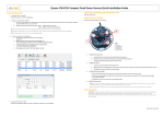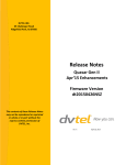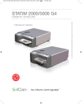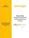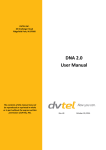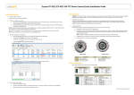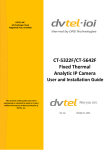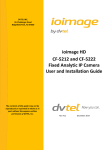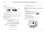
1
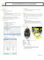
Quasar CM-3211/CM-4221/CM-4251 Mini-Dome Camera Quick Installation Guide Initial Configuration 4. Disconnect the cable: 1. Prepare the camera: Remove the camera’s protective packaging and open the dome cover. 2. Attach an Ethernet cable: a. b. Connect one end of a Cat 5 Ethernet cable to the Ethernet port on the side of the camera, and the other end (RJ45) to a Power Sourcing Equipment (PSE) device, such as a PoE switch. 1. Mount the camera: a. NOTE: If you are using IE 9 as your web browser, work in Compatibility Mode. b. To open the DNA Assign IP screen, do one of the following: Select the unit, right-click the mouse, and select the Assign IP option Select the Assign IP button from the toolbar c. If your network does not have a DHCP server, enter the IP Address, Mask (Netmask) and Gateway values in the dialog box displayed below. d. Click Update and wait for Install the Quasar mini-dome camera in the ceiling according to the camera’s user manual. 2. Attach cables: 3. Set the camera’s IP address: Open the DNA application. Select the unit requiring IP assignment. See figures below. Refer to the camera’s user manual for mounting instructions. WARNING: The Quasar CM series camera must be kept in a clean and dry indoor environment or in the protective outdoor mounting kit supplied with the outdoor model. Operating temperature should be maintained within -10°C ~ 50°C (14° ~ 122°F). Operating humidity should be between 10-90% (non-condensing). The camera should be kept dry, free from water condensation, dust, dirt, and smoke. TIP: A camera setup adapter, such as Veracity Pinpoint, can be used to connect a laptop directly to the camera using PoE. a. Disconnect the Ethernet cable and replace the dome cover. The camera is ready for mounting in a site installation. b. Site Installation Verify that the LED on the port is green, indicating a good network connection. A yellow LED flashes when there is network activity. NOTE: The camera IP Address and the subnet mask IP Address are automatically supplied by the DHCP server. a. Thread cables through opening at the side of the camera: a. Plug the Cat 5 cable into the camera Ethernet port and plug the other end of the cable into an IEEE 802.3at PoE switch. If operating the heater for outdoor models, also plug a properly rated 24VAC cable into the camera power connector. b. If applicable, connect the Alarm In, Alarm Out, Audio In and Audio Out terminals to external devices. See the figures and table below. Adjust Camera Settings Note the following locations on the camera: OK status to be displayed. The IP value has been assigned. Figure A: Input/Output Connections 1 2 3 4 5 6 Name Description Lens Focus Fixing knob Zoom Fixing knob Tilt Fixed Screw Input/Output Connections Reset Button Camera lens To set the focus To set the zoom To set the tilt Refer to Figure A Restores default settings To adjust the focus: Loosen and tighten by hand the adjustment knob until the optimum focus is obtained. To adjust the zoom: Loosen and tighten by hand the adjustment knob until the optimum zoom is obtained. To adjust the tilt: Loosen the screw to adjust the tilt angle. CM-3211/4221/4251_QIG_Oct21_2013 Adjusting and Framing-Up the Camera View Attach in Latitude 1. Camera Access and Login: Access the camera in one of the following ways: a. If using the DNA application, click the DNA icon shortcut menu, and select Browse. b. If using a web browser, enter the camera’s IP address in the URL address bar. 1. In the Latitude application, on the Sidebar click Physical View. 2. 3. On the Navigation Tree click the System name. Select the Discovery tab and do the following: a. Under Cameras and Encoders, verify that DVTEL HD Series is selected. . In the Discovery List, click to select the camera, right-click to open the 2. Before logging into the camera: The client application will be automatically installed once you connect to the camera through your PC/workstation web-browser for the first time. Before accessing the camera, ensure that ActiveX controls can be downloaded by (a) changing the ActiveX controls and plug-in settings or (b) setting the Internet security level to default. For further details, refer to the camera’s user manual. ActiveX Controls and Plug-in Settings 1. 2. 3. 4. 5. 6. Start Internet Explorer. Select Tools from the main menu of the browser. Click Internet Options. Click the Security tab and select Internet. Click Custom level to change ActiveX settings. Set ActiveX controls and plug-ins items to Prompt or Enable. 6. 7. Click Start. The camera details are displayed in the Discovery table. c. If the camera wasn’t found after running Start, click Discover Unit Manually. d. In the dialog box that opens, enter the camera’s IP address, select DVTEL HD Series, and click OK. 4. In the Discovery table, right-click the camera, choose Attach, and then click the Archiver name to attach to. 5. When finished, click Internet Security Level 1. 2. 3. 4. 5. b. Start Internet Explorer. Select Tools from the main browser menu. Click Internet Options. Click the Security tab and select Internet. Page down, press Default Level and click OK to confirm. Close the browser window. To access the camera, open a new browser window. 3. Camera Login: The camera’s IP address is automatically supplied by the DHCP server. To access the camera for the first time, use the Configurator application to change the camera’s IP address. 4. Login ID and Password: a. Enter the camera’s IP address in the browser’s URL address bar and press the Enter key. b. Enter the default user name (Admin) and password (1234). to save. NOTE: The user name is case-sensitive. 5. Install the ActiveX control: a. b. c. d. After accessing the camera through the web browser for the first time, a request to install the ActiveX control appears below the URL address bar. Right-click on the message, and select Install ActiveX Control… to permit ActiveX control installation. In the pop-up security warning window, click Install to start downloading the DC Viewer software onto the PC. Click Finish when the DC Viewer installation is completed. NOTE: Uninstall previous versions of DC Viewer from your PC through the Windows Add/Remove program, before accessing the camera for the first time. For more information, refer to the user’s manual. Models in the CM Series: Model Number CM-3211-00 CM-3211-01 CM-3211-10 CM-3211-10-I CM-3211-11 CM-3211-11-I CM-4221-00 CM-4221-01 CM-4221-10 CM-4221-10-I CM-4221-11 CM-4221-11-I Description CM-4521-10-I CM-4521-11-I Indoor camera with varifocal lens Outdoor camera with varifocal lens Indoor camera with motorized lens Indoor camera with motorized lens and infrared IR illuminator Outdoor camera with motorized lens Outdoor camera with motorized lens and infrared IR illuminator How to Contact DVTEL: North America: 1-888-DVTel77 Latin America: +52 555580 5618 EMEA: +44 (0) 1494 430240 APAC: +65 6389 1815 China: +86 10 8586 8836 India: +91 (129) 431 5031 ANZ/Pacific: +61 8 8235 9211 For assistance, email us at [email protected] or visit http://www.dvtel.com/support. © DVTEL, Inc. All rights reserved worldwide. Printed October 2013.