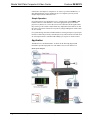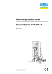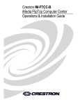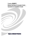
1
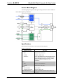
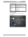
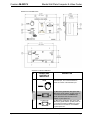
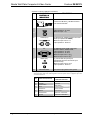
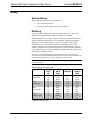
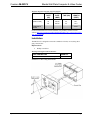
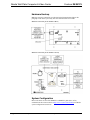
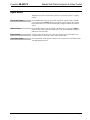
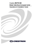
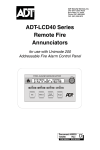
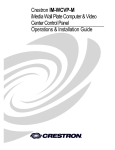
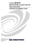
Crestron IM-WCCV
iMedia Wall Plate Computer & Video Center
Operations & Installation Guide
This document was prepared and written by the Technical Documentation department at:
Crestron Electronics, Inc.
15 Volvo Drive
Rockleigh, NJ 07647
1-888-CRESTRON
All brand names, product names and trademarks are the property of their respective owners.
©2007 Crestron Electronics, Inc.
Crestron IM-WCCV
iMedia Wall Plate Computer & Video Center
Contents
iMedia Wall Plate Computer & Video Center: IM-WCCV
1
Introduction ............................................................................................................................... 1
Features and Functions ................................................................................................ 1
Application .................................................................................................................. 2
Internal Block Diagram ............................................................................................... 3
Specifications .............................................................................................................. 3
Physical Description.................................................................................................... 4
Industry Compliance ................................................................................................... 7
Setup .......................................................................................................................................... 8
Network Wiring........................................................................................................... 8
IM Wiring.................................................................................................................... 8
Installation ................................................................................................................... 9
Hardware Hookup ..................................................................................................... 10
System Configuration................................................................................................ 10
Operation ................................................................................................................................. 11
Problem Solving ...................................................................................................................... 12
Troubleshooting......................................................................................................... 12
Reference Documents................................................................................................ 13
Further Inquiries ........................................................................................................ 13
Future Updates .......................................................................................................... 13
Return and Warranty Policies .................................................................................................. 14
Merchandise Returns / Repair Service ...................................................................... 14
CRESTRON Limited Warranty................................................................................. 14
Operations & Installation Guide – DOC. 6540A
Contents • i
Crestron IM-WCCV
iMedia Wall Plate Computer & Video Center
iMedia Wall Plate Computer &
Video Center: IM-WCCV
Introduction
Features and Functions
• A simple, affordable wall plate multimedia interface
• Streamlined user controls for foolproof operation
• iMedia Transport for fast and easy single-cable installation
• Supports XGA resolution up to 84 feet (25.6 meters), UXGA maximum
up to 34 feet (10.37 meters)
• Supports composite video signals
• Complete system setup in minutes using iMedia Wizard Software
The Crestron® iMedia products provide an extremely simple and affordable
multimedia presentation solution for small conference rooms and training rooms. No
comparable solution comes close to matching iMedia's speed and ease of installation,
intuitive operation, and incredibly low cost.
The iMedia Transport
The iMedia transport utilizes a single CresCAT™ CAT5e type cable, CresCAT-IM,
to transmit computer RGB, video, and stereo audio signals to a single projector or
plasma display. A typical XGA signal (1024 X 768 pixels at 60Hz) can be
transmitted up to 84 feet (25.6 meters) using iMedia, while higher resolutions up to
1600 x 1200 can be handled over shorter distances. Audio is transmitted digitally at
20-bit, 48 kHz resolution. Control and power signals are also contained on the same
wire, eliminating the need for separate control or power cables.
Wall Plate Multimedia Interface
The IM-WCCV is an iMedia (IM) transmitter designed to install in a standard threegang electrical box, providing composite video, RGB, and stereo audio inputs for
Operations & Installation Guide – DOC. 6540A
iMedia Wall Plate Computer & Video Center: IM-WCCV • 1
iMedia Wall Plate Computer & Video Center
Crestron IM-WCCV
connection to the output of a computer or AV source. Up to three IM-WCCVs, or
other IM transmitters, may be installed as part of a complete system to provide
multiple input locations within the room.
Simple Operation
Every IM system is easy and intuitive to use. A simple press of the VIDEO or PC
buttons on the face of the IM-WCCV selects the appropriate input, turns on the
projector (or plasma, etc.), lowers the screen or lift, and routes all the signals where
they need to go. The volume control affords easy adjustment of the audio level, and
the entire system can be turned off at any time by simply holding down either button
for five seconds.
For systems having more than one IM transmitter, selecting an input at a given input
location overrides the previously selected input at any other location. The audio level
for each input location is controlled individually by its respective volume control.
Application
The IM-WCCV is an IM transmitter. As shown in the following diagram, IM
transmitters provide input points for video and PC sources on an IM receiver.
iMedia System Diagram
2 • iMedia Wall Plate Computer & Video Center: IM-WCCV
Operations & Installation Guide – DOC. 6540A
Crestron IM-WCCV
iMedia Wall Plate Computer & Video Center
Internal Block Diagram
The following diagram represents the signal routing and functions of the IM-WCCV.
Internal Block Diagram of the IM-WCCV
Specifications
Specifications for the IM-WCCV are listed in the following table.
IM-WCCV Specifications
SPECIFICATION
DETAILS
RGB
Gain
0dB (75 ohm termination)
Formats
RGBHV, RGBS, RGsB
Resolution
1024 x 768 @ 60Hz with maximum cable length of
84 feet (25.6 meters), 1600 x 1200 @ 60Hz with
maximum cable length of 34 feet (10.37 meters).
Refer to “IM Wiring” on page 8 for other
resolutions.
Video
Gain
0dB (75 ohm termination)
Formats
480i (NTSC), 576i (PAL)
Audio
A-D Conversion
20-bit, 48kHz
Frequency Response
20Hz to 20kHz ±1dB
Power Requirements
Power is provided by the IM receiver via the IM
transport
(Continued on following page)
Operations & Installation Guide – DOC. 6540A
iMedia Wall Plate Computer & Video Center: IM-WCCV • 3
iMedia Wall Plate Computer & Video Center
Crestron IM-WCCV
IM-WCCV Specifications (Continued)
SPECIFICATION
DETAILS
Environmental
Temperature
41° to 104°F (5° to 40°C)
Humidity
10% to 90% RH (non-condensing)
Enclosure
3-gang wall plate, mountable in a 2.5 in (6.35 cm)
deep electrical box
Dimensions
Height
4.50 in (11.43 cm)
Width
6.36 in (16.16 cm)
Depth
2.95 in (7.48 cm)
Weight
1.29 lbs (0.58 kg)
Physical Description
This section provides information on the connections, controls, and indicators
available on your IM-WCCV.
IM-WCCV Physical View
4 • iMedia Wall Plate Computer & Video Center: IM-WCCV
Operations & Installation Guide – DOC. 6540A
Crestron IM-WCCV
iMedia Wall Plate Computer & Video Center
IM-WCCV Overall Dimensions
Connectors, Controls & Indicators
#
CONNECTORS,
CONTROLS &
INDICATORS
1
VOLUME CONTROL
KNOB
2
VIDEO BUTTON
(1) Momentary pushbutton with green LED;
Momentary press initiates “system power on”
command and selects local VIDEO input;
press and hold for five seconds or more
initiates “system power off.”
3
PC BUTTON
(1) Momentary pushbutton with green LED;
Momentary press initiates “system power on”
command and selects local PC input; press
and hold for five seconds or more initiates
“system power off.”
DESCRIPTION
Turn clockwise to raise the volume of the
selected input; turn counterclockwise to
lower the volume of the selected input.
(Continued on the following page)
Operations & Installation Guide – DOC. 6540A
iMedia Wall Plate Computer & Video Center: IM-WCCV • 5
iMedia Wall Plate Computer & Video Center
Crestron IM-WCCV
Connectors, Controls & Indicators (Continued)
#
CONNECTORS,
CONTROLS &
INDICATORS
4
TO IM-RXV RECEIVER
DESCRIPTION
(1) 8-wire female RJ-45 connector for iMedia
connection to IM-RXV1 or IM-RXV3 receiver
over CresCAT-IM cable1.
Pin 1
(1) RCA female, composite video input;
Input Impedance: 75 ohms;
Maximum Input: 1 Vp-p
5
VIDEO
6
AUDIO (R-L)
7
PC
(1) DB15HD female, RGB (VGA) input;
Formats: RGBHV, RGBS, RGsB;
Input Impedance: 75 ohms;
Sync Impedance: 1k ohms;
Maximum Input Level: 1 Vp-p;
Maximum Sync Level: 5 Vp-p2
8
AUDIO (PC)
(1) 3.5mm TRS mini phone jack;
Unbalanced stereo line-level audio input
(linked with PC);
Maximum Input Level: 2 Vrms;
Input Impedance: 10k ohms
9
GROUND WIRE
Connect the flying lead to earth ground.
(2) RCA female; unbalanced stereo line-level
audio input (linked with VIDEO);
Maximum Input Level: 2 Vrms;
Input Impedance: 10k ohms
1. The eight-pin RJ-45 iMedia port accepts CresCAT-IM or CAT5E/CAT6 carrying video, audio, power
and control signals. Refer to the following table for connector pinouts. Power is supplied to pins 4 and
5 from the IM receivers.
PIN
WIRE COLORS (EIA 568B)
iMEDIA ASSIGNMENT: RGB,
COMPOSITE AND AUDIO
1
WHITE/ORANGE
- RGB RED
2
ORANGE
+ RGB RED
3
WHITE/GREEN
- RGB GREEN
4
BLUE
+ AUDIO / POWER
5
WHITE/BLUE
- AUDIO / POWER
6
GREEN
+ RGB GREEN
7
WHITE/BROWN
- RGB BLUE / COMPOSITE
8
BROWN
+ RGB BLUE / COMPOSITE
6 • iMedia Wall Plate Computer & Video Center: IM-WCCV
Operations & Installation Guide – DOC. 6540A
Crestron IM-WCCV
iMedia Wall Plate Computer & Video Center
2. This female DB15HD connector is used for connecting a computer’s RGB video output to the display
device. Refer to the following table for pin assignments:
PIN
FUNCTION
PIN
FUNCTION
PIN
FUNCTION
1
Red Video
6
Red Ground
11
No Connect
2
Green Video
7
Green Ground
12
Monitor Sense 1
3
Blue Video
8
Blue Ground
13
Horizontal Sync
4
Reserved
9
No Connect
14
Vertical Sync
5
Ground
10
Ground
15
Monitor Sense 2
Industry Compliance
As of the date of manufacture, the IM-WCCV has been tested and found to comply
with specifications for CE marking and standards per EMC and
Radiocommunications Compliance Labelling.
NOTE: This device complies with part 15 of the FCC rules. Operation is subject to
the following two conditions: (1) this device may not cause harmful interference and
(2) this device must accept any interference received, including interference that may
cause undesired operation.
Operations & Installation Guide – DOC. 6540A
iMedia Wall Plate Computer & Video Center: IM-WCCV • 7
iMedia Wall Plate Computer & Video Center
Crestron IM-WCCV
Setup
Network Wiring
When wiring the network, consider the following:
•
Use Crestron Certified Wire.
•
Use Crestron power supplies for Crestron equipment.
IM Wiring
Using a proprietary signal routing solution, RGBHV, audio, power, and control
signals are all transported using a single cable solution called iMedia.
The iMedia transport system port is capable of managing computer RGB and audio
signals simultaneously through one CresCAT-IM cable, simplifying installations.
Routing CresCAT-IM cable (low-skew CAT5e) is less expensive and a much
simpler solution for wiring iMedia systems than routing multi-colored, multiconductor coax cable. All Crestron products using the iMedia transport system are
capable of sending and receiving iMedia signals via CresCAT-IM cable. Installation
of any iMedia device is as simple as installing one iMedia cable from output to input.
Installations are affordable and fast.
The receiver can accomplish frequency compensation on each input to achieve
correct operation. This compensation scheme is effective for CresCAT-IM cables as
long as the maximum skew of 15 nS per 100 meters is not exceeded.
NOTE: For proper operation and performance of every iMedia system, always use
CresCAT-IM cable.
Maximum Resolution and Cable Length
RESOLUTION
REFRESH
RATE
(HZ)
PIXEL
RATE
(MHZ)
PIXEL
TIME (NS)
MAX
LENGTH
(FEET)
60
72
85
56
72
85
60
70
85
60
75
85
25.18
31.50
36.00
36.00
50.00
56.25
65.00
75.00
94.50
108.00
135.00
157.50
39.7
31.7
27.8
27.8
20.0
17.8
15.4
13.3
10.6
9.3
7.4
6.3
218.5
174.6
152.8
152.8
110.0
97.8
84.6
73.3
58.2
50.9
40.7
34.9
VGA
(640 X 480)
SVGA
(800 X 600)
XGA
(1024 X 768)
SXGA
(1280 X 1024)
(Continued on following page)
8 • iMedia Wall Plate Computer & Video Center: IM-WCCV
Operations & Installation Guide – DOC. 6540A
Crestron IM-WCCV
iMedia Wall Plate Computer & Video Center
Maximum Resolution and Cable Length (Continued)
RESOLUTION
REFRESH
RATE
(HZ)
PIXEL
RATE
(MHZ)
PIXEL
TIME (NS)
MAX
LENGTH
(FEET)
60
70
85
162.00
189.00
229.50
6.2
5.3
4.4
34.0
29.1
24.0
218.5
UXGA
(1600 X 1200)
COMPOSITE
VIDEO
For more information on CresCAT and other wire products, visit the Crestron
website (http://www.crestron.com/downloads/pdf/product_line_overviews/overviewwire_and_cable.pdf).
Installation
The IM-WCCV is designed to mount in a standard 2.5-inch (6.35 cm) deep, threegang, electrical box.
Required Tools:
•
Phillips screwdriver
Mounting Parts Supplied with the IM-WCCV
PART DESCRIPTION
Screw #6-32 x 1 in, Pan Head, Phillips
QUANTITY
4
Installation in a Three-Gang Electrical Box
Operations & Installation Guide – DOC. 6540A
iMedia Wall Plate Computer & Video Center: IM-WCCV • 9
iMedia Wall Plate Computer & Video Center
Crestron IM-WCCV
Hardware Hookup
Make the necessary connections as called out in the illustration that follows this
paragraph. Turn on the system only after all connections have been made.
Hardware Connections for the IM-WCCV (Rear)
Hardware Connections for the IM-WCCV (Front)
System Configuration
Refer to the latest version of the IM-RXV1 & IM-RXV3 guide (Doc. 6478),
available from the Crestron website (http://www.crestron.com/manuals) for iMedia
system configuration instructions.
10 • iMedia Wall Plate Computer & Video Center: IM-WCCV
Operations & Installation Guide – DOC. 6540A
Crestron IM-WCCV
iMedia Wall Plate Computer & Video Center
Operation
The IM-WCCV can be used to turn a system on or off, select a source, or adjust
volume.
Turn on the System
Press the PC button to turn on the system with the PC signals routed to the IM
receiver or press the VIDEO button to turn on the system with the video signals
routed to the IM receiver. The associated LED will light to indicate the selected
source.
Select a Source
Press the PC button to route PC signals to the IM receiver or press the VIDEO
button to route video signals to the IM receiver. The associated LED will light to
indicate the selected source.
Adjust Volume
Turn the volume knob clockwise to raise the volume of the selected input; turn
counterclockwise to lower the volume of the selected input.
Turn off the System
Press and hold the selected source button for five seconds. The source button LED
will flash and then turn off.
Operations & Installation Guide – DOC. 6540A
iMedia Wall Plate Computer & Video Center: IM-WCCV • 11
iMedia Wall Plate Computer & Video Center
Crestron IM-WCCV
Problem Solving
Troubleshooting
The following table provides corrective action for possible trouble situations. If
further assistance is required, please contact a Crestron customer service
representative.
IM-WCCV Troubleshooting
TROUBLE
Source LED
does not
illuminate.
No video
output
displayed.
No audio output.
POSSIBLE
CAUSE(S)
CORRECTIVE ACTION
Not receiving
power.
Verify that the iMedia cable is
connected to the IM-WCCV and the
IM-WCCV is connected to the
iMedia receiver.
Incorrect power
supply.
Only use Crestron power supplies.
Source is not
selected.
Push a source button to select a
source.
Incorrect cable
connection.
Verify computer cable connection.
Verify video cable connection.
Verify iMedia output cable connection
is secure.
Incorrect cable
connection.
Verify computer audio cable
connection.
Verify video input’s audio cable
connection.
Video from RGB
source is
garbled or no
output.
Incorrect cable
connections.
Verify 15-pin computer cable
connection. Verify iMedia output
cable connections.
Button does not
function when
pressed.
Incorrect cable
connection.
Verify that the iMedia output cable
connection from the IM-WCCV to the
iMedia receiver is secure.
Other functions
operate, but
does not control
the projector.
Incorrect connections
to projector.
Verify cable wiring and connections
between receiver and projector.
Verify maximum iMedia cable length.
Adjust delay on iMedia receiver.
12 • iMedia Wall Plate Computer & Video Center: IM-WCCV
Operations & Installation Guide – DOC. 6540A
Crestron IM-WCCV
iMedia Wall Plate Computer & Video Center
Reference Documents
The latest version of all documents mentioned within the guide can be obtained from
the Crestron website (http://www.crestron.com/manuals). This link will provide a list
of product manuals arranged in alphabetical order by model number.
List of Related Reference Documents
DOCUMENT TITLE
IM-RXV1 & IM-RXV3 iMedia
Receiver/Processor with Video
Further Inquiries
If you cannot locate specific information or have questions after reviewing this
guide, please take advantage of Crestron's award winning customer service team by
calling the Crestron corporate headquarters at 1-888-CRESTRON [1-888-273-7876].
For assistance in your local time zone, refer to the Crestron website
(http://www.crestron.com/) for a listing of Crestron worldwide offices.
You can also log onto the online help section of the Crestron website to ask
questions about Crestron products. First-time users will need to establish a user
account to fully benefit from all available features.
Future Updates
As Crestron improves functions, adds new features, and extends the capabilities of
the IM-WCCV, additional information may be made available as manual updates.
These updates are solely electronic and serve as intermediary supplements prior to
the release of a complete technical documentation revision.
Check the Crestron website periodically for manual update availability and its
relevance. Updates are identified as an “Addendum” in the Download column.
Operations & Installation Guide – DOC. 6540A
iMedia Wall Plate Computer & Video Center: IM-WCCV • 13
iMedia Wall Plate Computer & Video Center
Crestron IM-WCCV
Return and Warranty Policies
Merchandise Returns / Repair Service
1.
No merchandise may be returned for credit, exchange or service without prior authorization
from CRESTRON. To obtain warranty service for CRESTRON products, contact an
authorized CRESTRON dealer. Only authorized CRESTRON dealers may contact the factory
and request an RMA (Return Merchandise Authorization) number. Enclose a note specifying
the nature of the problem, name and phone number of contact person, RMA number and
return address.
2.
Products may be returned for credit, exchange or service with a CRESTRON Return
Merchandise Authorization (RMA) number. Authorized returns must be shipped freight
prepaid to CRESTRON, 6 Volvo Drive, Rockleigh, N.J. or its authorized subsidiaries, with
RMA number clearly marked on the outside of all cartons. Shipments arriving freight collect
or without an RMA number shall be subject to refusal. CRESTRON reserves the right in its
sole and absolute discretion to charge a 15% restocking fee plus shipping costs on any
products returned with an RMA.
3.
Return freight charges following repair of items under warranty shall be paid by CRESTRON,
shipping by standard ground carrier. In the event repairs are found to be non-warranty, return
freight costs shall be paid by the purchaser.
CRESTRON Limited Warranty
CRESTRON ELECTRONICS, Inc. warrants its products to be free from manufacturing defects in materials
and workmanship under normal use for a period of three (3) years from the date of purchase from
CRESTRON, with the following exceptions: disk drives and any other moving or rotating mechanical
parts, pan/tilt heads and power supplies are covered for a period of one (1) year; touchscreen display and
overlay components are covered for 90 days; batteries and incandescent lamps are not covered.
This warranty extends to products purchased directly from CRESTRON or an authorized CRESTRON
dealer. Purchasers should inquire of the dealer regarding the nature and extent of the dealer's warranty, if
any.
CRESTRON shall not be liable to honor the terms of this warranty if the product has been used in any
application other than that for which it was intended or if it has been subjected to misuse, accidental
damage, modification or improper installation procedures. Furthermore, this warranty does not cover any
product that has had the serial number altered, defaced or removed.
This warranty shall be the sole and exclusive remedy to the original purchaser. In no event shall
CRESTRON be liable for incidental or consequential damages of any kind (property or economic damages
inclusive) arising from the sale or use of this equipment. CRESTRON is not liable for any claim made by a
third party or made by the purchaser for a third party.
CRESTRON shall, at its option, repair or replace any product found defective, without charge for parts or
labor. Repaired or replaced equipment and parts supplied under this warranty shall be covered only by the
unexpired portion of the warranty.
Except as expressly set forth in this warranty, CRESTRON makes no other warranties, expressed or
implied, nor authorizes any other party to offer any warranty, including any implied warranties of
merchantability or fitness for a particular purpose. Any implied warranties that may be imposed by law are
limited to the terms of this limited warranty. This warranty statement supersedes all previous warranties.
Trademark Information
All brand names, product names and trademarks are the sole property of their respective owners. Windows is a registered trademark
of Microsoft Corporation. Windows95/98/Me/XP and WindowsNT/2000 are trademarks of Microsoft Corporation.
14 • iMedia Wall Plate Computer & Video Center: IM-WCCV
Operations & Installation Guide – DOC. 6540A
Crestron IM-WCCV
iMedia Wall Plate Computer & Video Center
This page is intentionally left blank.
Operations & Installation Guide – DOC. 6540A
iMedia Wall Plate Computer & Video Center: IM-WCCV • 15
Crestron Electronics, Inc.
15 Volvo Drive Rockleigh, NJ 07647
Tel: 888.CRESTRON
Fax: 201.767.7576
www.crestron.com
Operations & Installation Guide – DOC. 6540A
(2016642)
03.07
Specifications subject to
change without notice.