1
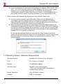
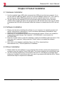
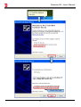
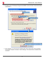
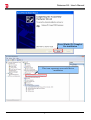
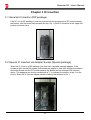
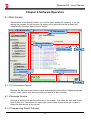
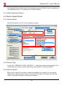
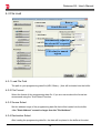
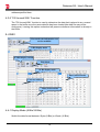
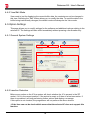
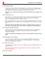
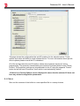
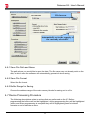
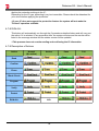
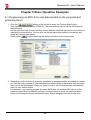
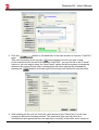
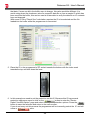
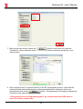
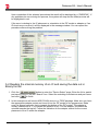
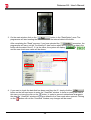
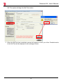
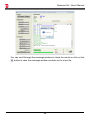
Dataman-S6 - User's Manual
Dataman-S6
Compact USB Programmer
User's Manual
Dataman-S6 - User's Manual
Contents
Chapter 1 Product Description
1-1 Introduction
1-2 Safety Information
1-3 Precautions
1-4 Operating System, Hardware Requirements
1-5 Accessories
Chapter 2 Product Installation
2-1 Hardware Installation
2-2 Software Installation
2-3 Driver Installation
Chapter 3 IC Insertion
3-1 General IC Insertion (DIP package)
3-2 Special IC Insertion via Adapter (Special package)
Chapter 4 Software Operation
4-1 Main Screen
4-1-1 IC Information Column
4-1-2 Message Window
4-1-3 Programming Result Statistics
4-1-4 Other Operation Buttons
4-2 Device Select/Project
4-2-1 Device Select
4-2-2 Device Type
4-2-3 Device Search
4-2-4 Device Search Operators
4-2-5 Device Search Results
4-2-6 Selected Device History
4-3 File Load
4-3-1 Load File Path
4-3-2 File Format
4-3-3 Source Select
4-3-4 Destination Select
4-3-5 “Fill Unused With” Function
4-4 Edit
4-4-1 Display Mode (8 Bits/16 Bits)
4-4-2 View/Edit Mode
4-5 Option Settings
4-5-1 General System Settings
4-5-2 Insertion Detection
4-5-3 Device ID Check
Dataman-S6 - User's Manual
4-5-4 Confirm Error List
4-5-5 Programming Area Selection
4-5-6 Message Column Settings
4-5-7 Self-Test Function
4-5-8 Device Options
4-6 Save
4-6-1 Save File Path and Name
4-6-2 Save File Format
4-6-3 Buffer Range for Saving
4-7 Device Processing Procedure
4-7-1 Read
4-7-2 Data Confirm
4-7-3 Erase
4-7-4 Blank Check
4-7-5 Program
4-7-6 Verify
4-7-7 Protect
4-7-8 RUN ALL
4-7-9 Description of Actions
Chapter 5 Basic Operation Examples
5-1 Programming an MCU from user data located on the computer and
protecting the IC
5-2 Reading the internal memory of an IC and saving the data out in Binary
format
5-3 Using the system's Self Test function to detect and test the programmers
hardware
Chapter 6 Troubleshooting
Chapter 7 Glossary of Terms
Dataman-S6 - User's Manual
Chapter 1 Product Description
1-1 Introduction
With 30 years experience Dataman is the world’s leading provider of device programmers. We offer
a comprehensive range of programming solutions suitable for every requirement from design and
development to large scale production.
We are committed to providing continued development, manufacturing and support and to deliver
customer specific innovative solutions.
All Dataman products come with comprehensive warranties, free lifetime support and free software
updates via our website and telephone helpdesk.
1-2 Safety Information
All the operations, maintenance and repair services are required to follow the below safety
information. We do not take responsibility for unexpected problems by misusing the equipment.
1. The programmer must be connected to the host computer using the supplied Y type USB
cable. Check that both USB plugs are connected to the computer and confirm that the
available USB power is sufficient to operate the programmer correctly. If the computer is
connected through a USB Hub it will need to be a powered hub (+5V/1A or above).
2. Do not operate the product near flammable gases. High-temperatures and humidity should
also be avoided.
3. Do not remove the product's case to adjust or replace any internal parts.
4. Sockets or adapters are considered consumables. The life time is determined from the
frequency of use specified in the manufactures specification. If a socket is used beyond the
rated number of actuations specified by the manufacturer, the socket will start to give errors
caused by poor contact. This will result in an increasing number of contact errors and burn
failures.
5. When using this product as mass production or production for master tape, please take the
appropriate testing precautions before assembling the completed product. All the risks
attributed to using the product or operating the software are undertaken by the user.
6. This manual is for reference and preservation of the consumer. Product specifications and
manuals are subject to change without notice.
7. The company or trademarks mentioned in this manual are the property of their respective
owners.
1-3 Precautions
1. When you work with your IC using our programmer it will access the device using a high
frequency signal. To ensure proper programming and high yield rates you must observe the
following:
a) During any operation with the IC (read / verify / programming / erase / blank check ...
etc) do not touch the IC or ZIF socket. When inserting an IC into the ZIF socket,
please take note of basic electrostatic protection measures.
1
Dataman-S6 - User's Manual
b) If you need adapters for other kinds of IC package (for example, TSOP, PLCC, TQFP,
QFN ... etc.) we would advise that you contact Dataman. Do not use inferior quality
adapters or try to create adapters yourself. The Dataman-S6 programmer
communicates with the IC using a high-frequency signal. If external adapters are of
poor quality we will be unable to give any guarantee on the programming results!
2. When connecting the Dataman-S6 programmer to the computer please note:
a) You must use the supplied Y-type USB cable. Check that both USB plugs are
connected to the host computer before connecting the programmer. An ordinary
single USB cable is not suitable as it will not supply enough power to the unit and you
may experience problems with stability during programming.
b) When the Dataman-S6 software is launched and connection to the programmer is
established the programmer will check the USB power supply, if the power supply is
not sufficient a warning message will be displayed. If you are using an external USB
hub its supply may be limited. In which case you would need to use a power adapter
capable of (5V, 1A or greater) to improve it.
On the warning message window you can press the "Retry" button to re-test the
supply once you have made a change. You can also press the "Cancel" button to skip
the power detection. However by doing so the system can not guarantee 100%
correct operation.
1-4 Operating System, Hardware Requirements
Operating System:
Windows XP / Windows Vista / Windows 7
CPU:
PC / Pentium IV or above
Memory:
512 MB RAM or above
Hard disk space:
500 MB or more (main program)
1 GB or more (program buffer (depending on
selected device capacity))
Monitor Resolution:
800 x 600 pixels or above
Interface:
USB 2.0 High Speed
2
Dataman-S6 - User's Manual
Power Requirements:
2 x USB Ports providing +5 V power supply
Dimensions:
130 (L) x 90 (depth) x 20 (high) mm
Note: Height does not include ZIF Socket
Weight:
290g
Operating temperature:
+5 ℃to +45 ℃
1-5 Accessories
Programmer:
1
Special Y-USB cable:
1
CD-ROM (software and manual):
1
3
Dataman-S6 - User's Manual
Chapter 2 Product Installation
2-1 Hardware Installation
1. Use the supplied Y-type USB cable connected two USB ports on the host computer. If you
use an external USB Hub, please connect it to a power adapter rated at (5V,> 1A or above),
and remove any other USB powered devices such as external hard drives...and so on.
2. The blue LED on the Dataman-S6 will not illuminate until the software driver has been
installed. After installing the driver the programmers' LED will flash twice then turn off. When
in operation the LED will be illuminated, when the software is closed down the LED will turn
off.
2-2 Software Installation
1. Please note that when installing the software on your computer, the operating system will
require "administrator" permissions. If you do not have administrator permissions it may
result in an unsuccessful installation.
2. Insert the CD, the installation screen should automatically appear. If there's no installation
screen please install through "My Computer" > CD-ROM drive > and execute the
AUTORUN.EXE
3. Press the "Install" button to start the installation, modify the installation path and name of the
start menu link if required. Finally press the "Finish" button to complete the software
installation.
4. Next, click on the database installation files on the CD (or download from
www.dataman.com). This will update the IC database.
2-3 Driver Installation
1. Please install the main software on your computer first and then connect the programmer to
computer using the supplied Y-type USB cable. The driver installation will automatically start.
2. The first time the programmer is connected to the host PC it will display a message about
finding new hardware, and will then ask if you want to go ahead and install the driver. Please
follow these steps to complete the installation.
4
Dataman-S6 - User's Manual
Check this item
5
Dataman-S6 - User's Manual
3. The path is set to "C:\Dataman Programmers\USBDrv" (Check the item “Include this location
in the search”.)
check this item
check this item
Set the driver path
Choose to continue the installation
4. After installation, you will see the the "Dataman-S6” device listed under “Device manager”Control Panel \ System \ Hardware \ Device Manager. This shows that the installation was
successful.
6
Dataman-S6 - User's Manual
Press [Finish] To Complete
the installation
This icon represents successful driver
installation
7
Dataman-S6 - User's Manual
Chapter 3 IC Insertion
3-1 General IC Insertion (DIP package)
If the IC is in a DIP package it must be inserted into the programmers ZIF socket towards
the bottom, with the index mark towards the top. Pin 1 of the IC should be at the upper left
position as shown here.
3-2 Special IC Insertion via Adapter Socket (Special package)
When the IC is not in a DIP package you must use a suitable package adapter. If the
number of pins on the DIL header underneath the adapter is less than 48 then the adapter
should be placed into the ZIF socket towards the bottom as with standard DIP devices
above. The adapters are usually marked with a "1" to indicate the position of pin 1 on the
device. Place the IC into the adapter socket matching the position of pin 1.
8
Dataman-S6 - User's Manual
Chapter 4 Software Operation
4-1 Main Screen
Shown below is the default interface you will see when starting the software. If you are
starting the program for the first time no device will be selected and the software will
automatically show the "Select Device" screen.
The function key
IC Information
Message Column
Saving
Clear all messages
The results of a single
programming
Programming Results Statistics
Zeroing
4-1-1 IC Information Column
Displays the device's brand, serial number and packaging information. Programming data
source, notes, check sum value and other information is also included.
4-1-2 Message Window
Records all actions and results performed on the system. It will show the date and time in
front of each line. The buttons on upper right corner of this window allow you to save or
delete the data shown in this column.
4-1-3 Programming Result Statistics
9
Dataman-S6 - User's Manual
A running total of the statistic results from programming (only [RUN ALL] are recorded here).
The right hand button- [>> 0] allows you to clear the results.
4-1-4 Other Operation Buttons
4-2 Device Select/Project
4-2-1 Device Select
Allows the selection of an IC by full or partial part name.
Manufacturer LOGO
Search
Selected Device
Manufacturer
Part Number
(package)
IC Information
4-2-2 Device Type
IC type (ALL / EEPROM / FLASH / MPU/MCU ...). Helps users select the appropriate IC by
narrowing down the type of device technology that is shown in the search results.
4-2-3 Device Search
Enter a full or partial IC part name to search the database for a match. You can use the
"Space" key to separate search terms. The order of the search terms does not affect the
results. The search operation is decided by operators.
10
Dataman-S6 - User's Manual
4-2-4 Device Search Operators
When multiple search terms are entered into this field the search result is performed in
accordance with ALL search terms (AND), OR some of the terms (OR).
4-2-5 Device Search Results
Shows the IC part names matching the search terms.
※ 4-2-2 and 4-2-3 will change the search results based on type of device and part name.
4-2-6 Selected Device History
The system will automatically record the last 20 selected devices. You can directly select any
device from this list.
※ The brand names and logos shown in our software remain the property of the
respective companies.
11
Dataman-S6 - User's Manual
4-3 File Load
Browse
Search Records
Automatically adjust to
the selected IC's capacity
Fill value for unused
regions
4-3-1 Load File Path
The path to your programming data file (HEX, Binary...) that will be loaded into the buffer.
4-3-2 File Format
Select the format of the programming date file. If you are unsure about the format we
recommend using the "Auto Detect" function.
4-3-3 Source Select
Set the address range of the programming data file that will be loaded into the buffer.
※ the "Start Address" cannot be larger than the "End Address".
4-3-4 Destination Select
After loading the programming data file, the data will be placed in the buffer at the start
12
Dataman-S6 - User's Manual
address specified here.
4-3-5 “Fill Unused With” Function
The "Fill Unused With" function is used to determine the data that is placed in any unused
space in the buffer once the users data file has been loaded (the data file may not be
contiguous). Leaving this option unchecked will preserve whatever information is already in
the buffer.
4-4 Edit
View mode, the information can
not be modified
8 Bit display mode
8/16bit display switch
Edit Mode
16 Bit display mode
Data (ASCII mode)
Current Address
Data (16 hex mode)
4-4-1 Display Mode (8 Bits/16 Bits)
Switch the data format between: Bytes (8 Bits) or Words (16 Bits)
13
Dataman-S6 - User's Manual
4-4-2 View/Edit Mode
View mode is just for displaying the current buffer data, the contents can not be changed in
this view. Selecting the "Edit" button allows you to modify the data. To avoid the data in the
buffer being inadvertently changed, the default mode will always be the View mode.
4-5 Option Settings
This page allows you to modify settings for the software and additional options relating to the
selected IC. The settings will take effect immediately without pressing a confirmation key.
4-5-1 General System Settings
1
2
3
4
5
6
4-5-2 Insertion Detection
Before every action on the IC the system will check whether the IC is present in the ZIF
socket, if it is in the correct position, if the socket is empty or if there is a bad connection. If
there is a problem it will stop performing further actions and display a message.
If this option is not checked, the programmer will not perform the above checks.
※ If the item can not be checked this means that the selected IC does not support this
function.
14
Dataman-S6 - User's Manual
4-5-3 Device ID Check
This option checks the device's ID and compares it to the ID held in the database before
carrying out any actions on the IC. If the ID read from the device does not match the ID held
in the database, the system will not perform any further actions on the IC.
※ If the item can not be checked, this means that the selected IC does not support this
function.
4-5-4 Confirm Error List
When this item is not checked, pressing the "Confirm" button will compare whether the data
in the IC is the same as the data in the buffer. If the result is the same, it will display a
"Pass", if the data does not match, it will show a "Fail".
When checking the data the system will list any differences between the buffer and the IC in
the message window. The number of lines used to display the errors can be set at up to 999
lines.
※ When the option "[Confirm] Error lines shown" is checked, it will not compare any
of the device configuration options for the device, only the main user memory area.
4-5-5 Programming Area Selection
Select the area of the IC to be programmed. The main memory area will automatically be
enforced during programming however, other areas (if present) can be checked or
unchecked as required.
※ "Read"- All data will be read from the device back to the computer and stored in the
buffer.
4-5-6 Message Column Settings
Here you can set the number of lines used for messages (1000-5000 lines). When the
number of messages reaches the set limit you can choose whether to "Auto Clear and
Save" or just "Auto Clear" and continue.
4-5-7 Self-Test Function
The programmer will perform a self-test on its hardware and show the detailed results in the
message window.
※ Ensure that the ZIF socket is empty and do not place an IC or adapter in the ZIF
socket during this test.
4-5-8 Device Options
15
Dataman-S6 - User's Manual
This page shows the configuration bits and ID locations for the selected device. These
options and values will differ for each selected device. For more information about specific
device options please consult the IC's datasheet.
All of the configuration bits and ID location values are programed into the IC during
programming. The protection related setting are however excluded (Write Protect / Read
Protect). The protection settings are programmed into the IC using the separate “Protect”
button on the left hand “Procedure” menu which is not selected by default.
※ If there is no Device Options screen displayed it means that the selected IC does not
have any related configuration parameters.
4-6 Save
Save out the contents of the buffer to a user specified file in a variety formats.
16
Dataman-S6 - User's Manual
File browser
Automatically set to the capacity of
the currently selected IC
4-6-1 Save File Path and Name
The path where you would like to save the data. The file name may not already exist on the
disk, in which case the software will automatically generate it when saving.
4-6-2 Save File Format
Select the file format.
4-6-3 Buffer Range for Saving
Choose the address range of the main memory blocks for saving out to a file.
4-7 Device Processing Procedure
The following descriptions relate to actions that are performed on the IC. Before
programming the buttons will not be highlighted, during programming they will be highlighted
yellow, and when programming is complete they will be highlighted green to indicate
success or red to indicate an error.
17
Dataman-S6 - User's Manual
4-7-1 Read
Read all internal data (including configuration and/or ID locations) from the IC to the buffer.
You can view the data in the “Edit” window, the configuration bits and ID location values read
from the device can be seen via: "Option" → "Device Options"
4-7-2 Confirm
Confirms the data in the buffer is the same as the data in the IC. You can select to display
just "PASS / FAIL"(default) or to list the errors and address information.(Check the
Option→[Confirm] Error Lines Shown, up to 999 lines)
After checking the box to the left of the option, the confirmation function will be implemented
automatically following a "Read" operation.
※ After checking the box for "[Confirm] Error Lines Shown", the system will display
the error address and information in the information window. The IC configuration
bits and/or ID location values are not included in this check.
4-7-3 Erase
Will erase all the internal data in the IC to the default values(Including configuration bits
and/or ID location values and protection settings).
Unless you are sure that the IC is new or already blank we would suggest adding this
function when programming.
※ If the selected IC is OTP or EPROM based then the erase function is not available.
※ There is default information already stored in some types of IC (MPU or NAND
FLASH, etc.) The erase function will either, not erase this default data, or the data will
be written-back to the device after an erase. Which method is determined by whether
the IC permits the programmer to implement this function.
4-7-4 Blank Check
Checks that the memory area and all settings in the IC are set to their default states.
4-7-5 Program
Programs the data stored in the buffer along with the related configuration settings to the IC.
4-7-6 Verify
Checks whether the programmed data and related settings in the IC is exactly the same as
the the data in the buffer.
4-7-7 Protect
18
Dataman-S6 - User's Manual
Applies the protection settings to the IC:
Depending on the IC type, protecting it may be irreversible. Please check the datasheet for
your device before applying the protection.
※ If your IC does not support the protection feature the system will not make the
"Protect" operation available.
4-7-8 RUN ALL
This button will automatically run through the 5 procedures detailed below and will carry out
the action if it is selected. If any procedure fails, the system will stop and the results will be
listed in the message window and the statics counter will be updated.
※ This process does not contain reading and confirming the IC information
4-7-9 Description of Actions
Action
Normal
(No action)
Action
Read
Confirm
Erase
Blank Check
Program
Verify
Protect
RUN ALL
N/A
19
Pass
Fail
Dataman-S6 - User's Manual
Chapter 5 Basic Operation Examples
5-1 Programming an MCU from user data located on the computer and
protecting the IC
1. Click the
button on the top left to enter the "Device Select" page.
Then input the search keyword "AT89C51", the manufacturer column will list the matching
manufacturers.
On the right hand side, the part number column lists the individual part names of the devices
matching your search term. You can click on the part name that matches your device and
check any related notes below.
Finally press
to finish selecting the device and return to the main screen.
2. Depending on which device is selected, sometimes a message window will appear to remind
you that the newly selected IC has additional information blocks or parameter settings which
may need to be set/changed. When you select a new IC all of the parameters automatically
return to their default values.
For example, if you want to program the same MCU data into another MCU device of the
same part name but in a different package, you would have to check the additional data
blocks and change the device parameters again, after making the new device selection.
20
Dataman-S6 - User's Manual
3. Click the
button on left hand side of the main window to enter the "Load File"
page.
Then click the button at the top right
and navigate to the file you wish to load.
In this example the file format to be loaded is "Intel HEX", you can set this in the "Format"
column or you can simply check the "Auto Detect" option and let the system automatically
determine the correct format. After confirming that you have selected the intended file
pressing the
button in the lower right of the screen will load the file into the buffer.
4. After loading your file you can check the value shown by the "Check Sum" on the main
screen just above the message window. This checksum (byte sum x8) value is a
hexadecimal value generated from the data that is currently in the buffer and is unique to
21
Dataman-S6 - User's Manual
that data. If even one bit in the buffer were to change, this value would be different. It is
worth noting down the checksum value for a specific data file or from a master IC which has
been read into the buffer, this can be used at a later date to verify the data file or IC contents
have not changed.
With some IC's the "Check Sum" calculation requires the IC to be selected and the file
loaded into the buffer while the programmer is connected.
5. Place the IC in the programmer's ZIF socket towards the bottom with the index mark
towards the top and lock down the lever.
6. In this example we need to set the protection on this IC. Because this IC has several
protection options we need to click on the
button to enter the "Device
Option'\'Lock Bit Option" page and select the required protection options. Press the
button to save the selection and return to the main screen.
If you do not carry out this process the programmer will not correctly protect the IC and will
cause a
error.
22
Dataman-S6 - User's Manual
7. Back on the main screen, check the
button on the lower left under the
"Procedure" column and then check or uncheck the other procedures according to your
requirements.
8. After confirming the IC is placed correctly in the ZIF socket and is secure, check that the
selected device matches the device on the socket and that the checksum value is as
expected and click on the
button. The programmer will begin processing the
IC based on the selected procedures.
※ During the process of programming the IC do not disconnect the USB cable or
touch the socket components.
23
Dataman-S6 - User's Manual
Upon completion of the selected procedures the result will be displayed by a “PASS/FAIL". If
any problems do occur during the process, the system will stop and the failed process will
be highlighted in red.
If the error is relating to the IC placement or orientation in the ZIF socket or adapter or if an
ID check error occurred, it will be displayed in the message window. You can repeat the
procedure after solving the problem.
5-2 Reading the internal memory of an IC and saving the data out in
Binary format
1. Click the
button to enter the "Device Select" page. Enter the full or partial
part name of the IC into the "Search" box. Select the matching manufacturer and part name
and click
to finish.
2. In this example we will read a NOR FLASH device in a TSOP package. Make sure you have
the appropriate adapter socket and insert it into the ZIF socket of the programmer. Make
sure it is aligned correctly, that is towards the bottom of the ZIF socket. The adapter is
usually marked with a "1" to indicate the position of pin 1 on the adapter, this should be
oriented towards the top left. Follow the indication on the adapter socket for the correct
placement of the IC within the adapter.
24
Dataman-S6 - User's Manual
3. On the main window click on the
button in the "Data/Option" area. The
programmer will start reading the IC and will save the internal data to the buffer.
After completing the "Read" process, if you have selected the
procedure, the
programmer will carry out the “Confirming IC data" action which will compare the data in the
buffer with the data in the IC, if it is the same, the system will display
&
and the new check sum value will be shown.
4. If you want to check the data that has been read from the IC, simply click the
button on the left hand menu to enter the "View/Edit" window. In order to modify the data in
this view, you have the click on the
button. In order to prevent unintentional changes to
the data the “View/Edit” window will always default to the View mode when opened. Clicking
on the
button will exit the “View/Edit” window, any changes will be saved.
25
Dataman-S6 - User's Manual
5. Click the
button to enter the "Save File" window. Click the top right
button
and select where on your system you want to save the contents of the buffer. Select an
existing file to overwrite or enter a new file name. Click on the “Save” button to return to the
"Save File" window. Select the file format (Binary) in this example, and check that all the
settings are correct. Finally click on the
button to save the buffer contents out as a
Binary file to your PC.
5-3 Using the system's Self Test function to detect and test the
programmers hardware
1. Remove any IC or adapter from the programmer's ZIF socket. Running the Self Test routine
with a device or adapter in the ZIF socket may damage your programmer!
2. To access the Self Test option click on the
button from the left hand menu to
enter the "General" options page. After checking that the ZIF socket is empty, click on the
button towards the lower right hand side and then confirm the action by clicking
26
Dataman-S6 - User's Manual
OK. The system will begin the Self Test routine.
3. When the Self Test has completed a prompt will appear to inform you of this. Detailed results
of the Self Test will be displayed in the message window.
27
Dataman-S6 - User's Manual
You can scroll through the message window to check the results or click on the
button to save the message window contents out to a text file.
28
Dataman-S6 - User's Manual
Chapter 6 Troubleshooting
Status Description:
Software and/or driver did not install correctly. The software does not run correctly or at
all.
1
Troubleshooting:
Please make sure that you have "Administrator" permissions on the PC and then run the
software and driver installation again.
Status Description:
The software does not operate correctly or you suspect that something is wrong.
2
Troubleshooting:
Disconnect the programmer, restart the software and then reconnect the programmer.
Check the situation again.
Status Description:
Failure to detect the IC in the ZIF socket. Following error messages appear "Insertion
Detection Empty!", "Insertion Detection Fail!", "ID Check Fail!" or other similar error
messages.
3
Troubleshooting:
Check whether the IC is placed correctly in the ZIF socket? Is the direction and position
correct (towards the bottom of the socket, index mark pointing upwards)?
Check the IC pins are straight and free from flux, oxidization or some other residue?
If using an adapter, confirm whether it is the correct one. Is the adapter old or had a lot
of use? Adapters are consumable items and have limited life. Please purchase a new
adapter if required.
Status Description:
The software can not connect to the programmer (Message window shows "DatamanS6 Programmer not detected!").
4
Troubleshooting:
Check whether the programmer is connected using the supplied Y-type USB cable and
both USB connectors are plugged into the host PC.
Check whether the driver is installed correctly (Windows Device Manager).
Check whether the hosts USB Port is a USB 2.0 High Speed interface.
29
Dataman-S6 - User's Manual
Status Description:
After connecting to the programmer, the LED is not illuminated.
5
Troubleshooting:
Check whether the driver is installed correctly (Windows Device Manager).
Check whether the programmer is connected using the supplied Y-type USB cable and
both USB connectors are plugged into the host PC.
Status Description:
After the computer connects to the programmer, the LED flashes twice then goes out.
6
Troubleshooting:
Check whether the Dataman control software is running.
Check whether the driver is installed correctly (Windows Device Manager).
Check whether the hosts USB Port is a USB 2.0 High Speed interface.
Status Description:
When the software displays the below warning message it means the power supplied by
the hosts USB port is not sufficient. Click "Cancel" to ignore the message and continue,
however this may lead to unreliable operation.
Troubleshooting:
Use the supplied Y-type USB cable and connect both USB connectors to the host PC.
Change to another USB port.
Connect the programmer through an external powered USB Hub. (5V/1A or above)
7
30
Dataman-S6 - User's Manual
Status Description:
Self-Test function does not pass all of the tests.
8
Troubleshooting:
Please check whether there is an IC or adapter on programmer's ZIF socket as this will
cause the self test to fail. If the self test still fails, please send the self-test results to
[email protected] along with your company and contact details and someone will
contact you to advise the next steps.
31
Dataman-S6 - User's Manual
Chapter 7 Glossary of Terms
DIP:
Dual Inline Package
ZIF:
Zero Insertion Force socket
LED:
Light Emitting Diode
IC:
Integrated Circuit
USB:
Universal Serial Bus
OTP:
One Time Programmable
Buffer:
Part of PC memory or disk used for temporary data
storage
Intel Hex:
Intel HEX is a file format for conveying binary
information for applications like programming
microcontrollers, EPROMs, and other kinds of chips
Binary:
A binary file is a computer file that is not a text file; it
may contain any type of data, encoded in binary
form for computer storage and processing purposes
32