1
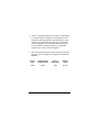
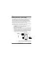
NT1 ACE
User Manual
1203019L1:
1203019L2:
1203019L3:
336048VUR-2:
61203019L1-1D
August 2002
NT1 ACE with Power Supply
NT1 ACE
NT1 ACE International
Power Supply
IMPORTANT SAFETY INSTRUCTIONS
When using your telephone equipment, basic safety precautions should always be followed to reduce the risk of
fire, electric shock and injury to persons. The precautions
are listed below.
1. Do not use this product near water (for example, near a bath tub, wash bowl, kitchen sink or
laundry tub, in a wet basement or near a swimming pool).
2. Never install telephone jacks in wet locations unless the jack is specifically designed for wet locations.
3. Avoid using a telephone (other than a cordless
type) during an electrical storm. There may be a
remote risk of electric shock from lightning.
4. Do not use the telephone to report a gas leak in the
vicinity of the leak.
5. Use only the power cord, power supply, and/or
batteries indicated in the manual. Do not dispose
of batteries in a fire. They may explode. Check local codes for any special disposal instructions.
6. Never touch uninsulated telephone wires or terminals unless the telephone line has been disconnected at the network interface.
7. Use caution when installing or modifying telephone lines.
SAVE THESE INSTRUCTIONS.
AFFIDAVIT REQUIREMENTS FOR CONNECTION TO
DIGITAL SERVICES
• An affidavit is required to be given to the telephone
company whenever digital terminal equipment without encoded analog content and billing protection is
used to transmit digital signals containing encoded
analog content which are intended for eventual conversion into voiceband analog signals and transmitted
on the network.
• The affidavit shall affirm that either no encoded analog content or billing information is being transmitted
or that the output of the device meets Part 68 encoded
analog content or billing protection specifications.
• End user/customer will be responsible to file an affidavit with the local exchange carrier when connecting
unprotected CPE to a 1.544 Mbps or subrate digital
services.
• Until such time as subrate digital terminal equipment
is registered for voice applications, the affidavit requirement for subrate services is waived.
61203019L1-1
NT1 ACE User Manual
iii
AFFIDAVIT FOR CONNECTION OF CUSTOMER
PREMISES EQUIPMENT TO 1.544 MBPS AND/OR
SUBRATE DIGITAL SERVICES
For the work to be performed in the certified territory of
_______________
(telco name)
State of ___________________
County of _________________
I, ______________________________(name),
________________________________(business address),
______________________ (telephone number) being duly
sworn, state:
I have responsibility for the operation and maintenance of
the terminal equipment to be connected to 1.544 Mbps
and/or ________ subrate digital services. The terminal
equipment to be connected complies with Part 68 of the
FCC rules except for the encoded analog content and billing protection specifications. With respect to encoded analog content and billing protection:
( ) I attest that all operations associated with the establishment, maintenance, and adjustment of the digital CPE
with respect to analog content and encoded billing protection information continuously complies with Part 68 of
the FCC Rules and Regulations.
( ) The digital CPE does not transmit digital signals containing
encoded analog content or billing information which is intended
to be decoded within the telecommunications network.
iv
NT1 ACE User Manual
61203019L1-1
( ) The encoded analog content and billing protection is
factory set and is not under the control of the customer.
I attest that the operator(s)/maintainer(s) of the digital
CPE responsible for the establishment, maintenance, and
adjustment of the encoded analog content and billing information has (have) been trained to perform these functions by successfully having completed one of the
following (check appropriate blocks):
( ) A. A training course provided by the manufacturer/
grantee of the equipment used to encode analog signals;
or
( ) B. A training course provided by the customer or authorized representative, using training materials and instructions provided by the manufacturer/grantee of the
equipment used to encode analog signals; or
( ) C. An independent training course (e.g., trade school
or technical institution) recognized by the manufacturer/
grantee of the equipment used to encode analog signals;
or
( ) D. In lieu of the preceding training requirements, the
operator(s)/maintainer(s) is (are) under the control of a
supervisor trained in accordance with _________ (circle
one) above.
I agree to provide _________________ (telco's name) with
proper documentation to demonstrate compliance with
the information as provided in the preceding paragraph,
if so requested.
61203019L1-1
NT1 ACE User Manual
v
_________________________________Signature
_________________________________Title
_________________________________ Date
Transcribed and sworn to before me
This ________ day of ________, 20___
_________________________________
Notary Public
My commission expires:
_________________________________
vi
NT1 ACE User Manual
61203019L1-1
FCC ID: HDC1203019L1
This device complies with Part 15 of the FCC rules. Operation is subject to the following two conditions: (1) This
device may not cause harmful interference, and (2) this
device must accept any interference received, including
interference that may cause undesired operation.
Changes or modifications to this unit not expressly approved by the party responsible for
compliance could void the user's authority to operate the equipment.
CANADIAN STANDARDS ASSOCIATION
This device must be powered by a CSA approved power
supply or a power supply meeting the requirements of
CS03, Part I Section 1.4.2.
FCC regulations require that the following information be
provided in this manual:
1. This equipment complies with Part 68 of the FCC
rules. On the bottom of the equipment housing is a label that shows the FCC registration number for this
equipment. If requested, provide this information to
the telephone company.
61203019L1-1
NT1 ACE User Manual
vii
2. If this equipment causes harm to the telephone network,
the telephone company may temporarily discontinue
service. If possible, advance notification is given; otherwise, notification is given as soon as possible. The
telephone company will advise the customer of the right
to file a complaint with the FCC.
3. The telephone company may make changes in its facilities, equipment, operations, or procedures that could affect the proper operation of this equipment; advance
notification and the opportunity to maintain uninterrupted service is given.
4. If experiencing difficulty with this equipment, please contact ADTRAN for repair and warranty information. The
telephone company may require this equipment to be disconnected from the network until the problem is corrected, or it is certain the equipment is not malfunctioning.
5. This unit contains no user-serviceable parts.
viii
NT1 ACE User Manual
61203019L1-1
6. An FCC compliant telephone cord with a modular plug
is provided with this equipment. In addition, an FCC
compliant cable appropriate for the dial backup option
ordered is provided with this equipment. This equipment is designed to be connected to the telephone network or premises wiring using an FCC compatible
modular jack, which is Part 68 compliant.
7. The following information may be required when applying to the local telephone company for leased line
facilities.
Service
Type
Digital Facility
Interface Code
Service
Order Code
Network
Jacks
ISDN
02IS5
6.0N
RJ-49C
61203019L1-1
NT1 ACE User Manual
ix
CANADIAN EMISSIONS REQUIREMENTS
This digital apparatus does not exceed the Class B limits
for radio noise emissions from digital apparatus as set
out in the interference-causing equipment standard entitled "Digital Apparatus," ICES-003 of the Department of
Communications.
Cet appareil numerique respecte les limites de bruits
radioelectriques applicables aux appareils numeriques
de Class B prescrites dans la norme sur le materiel brouilleur: "Appareils Numeriques," NMB-003 edictee par le
ministre des Communications.
CANADIAN EQUIPMENT LIMITATIONS
Notice: The Canadian Industry and Science Canada label
identifies certified equipment. This certification means that
the equipment meets certain telecommunications network
protective, operational, and safety requirements. The
Department does not guarantee the equipment will operate
to the user’s satisfaction.
Before installing this equipment, ensure that it is permissible to be connected to the facilities of the local telecommunications company. The equipment must also be
installed using an acceptable method of connection. In
some cases, the company’s inside wiring associated with
x
NT1 ACE User Manual
61203019L1-1
a single-line individual service may be extended by
means of a certified connector assembly (telephone
extension cord). Compliance with the above conditions
may not prevent degradation of service in some situations.
Repairs to certified equipment should be made by an
authorized Canadian maintenance facility designated by
the supplier. Any repairs or alterations made by the user
to this equipment, or equipment malfunctions, may give
the telecommunications company cause to request the
user to disconnect the equipment.
Users should ensure for their own protection that the
electrical ground connections of the power utility, telephone lines, and internal metallic water pipe system, if
present, are connected together. This precaution may be
particularly important in rural areas.
Users should not attempt to make such connections
themselves, but should contact the appropriate electric inspection authority, or an electrician, as
appropriate.
61203019L1-1
NT1 ACE User Manual
xi
The Load Number (LN) assigned to each terminal device
denotes the percentage of the total load to be connected
to a telephone loop which is used by the device, to prevent overloading. The termination on a loop may consist
of any combination of devices subject only to the requirement that the total of the Load Numbers of all devices
does not exceed 100.
xii
NT1 ACE User Manual
61203019L1-1
Table of Contents
Chapter 1. NT1 ACE Overview.................................. 1
LED Indicators .............................................................. 2
Chapter 2. Installation................................................. 3
Before Installing the NT1 ACE .................................... 3
Setting the Option Switches .......................................... 3
Termination Switch................................................. 3
TE can provide termination resistor: ...................... 4
TE does not provide termination resistor: ............... 4
Configuration Switch .............................................. 4
Powering with the NT1 Power Supply ......................... 6
Connecting the Terminal Equipment ............................ 7
Powering TEs from the NT1 ACE .......................... 8
Troubleshooting .......................................................... 10
Specifications .............................................................. 12
Network Interface (U) ........................................... 12
Customer Interface (S/T) ...................................... 12
61203019L1-1
NT1 ACE User Manual
xv
Table of Contents
Faceplate Indicators ...............................................12
Network Compatibility ..........................................12
Mechanical ............................................................13
Power .....................................................................13
Environment ..........................................................13
Power Supply Specifications .................................13
Figures
Figure 1-1. ADTRAN NT1 ACE ..................................1
Figure 1-2. Interface Connectors ...................................1
Figure 2-1. Switch Locations ........................................3
Figure 2-2. Short Passive Bus Configuration
5
Figure 2-3. Extended Passive Bus Configuration .........5
Figure 2-4. Power Supply Connection ..........................6
Tables
Table 1-1. Status Indicators ...........................................2
Table 2-1. Network Connector Pin Assignments ..........9
Table 2-2. Local Bus Connector Pin Assignments ........9
xvi
NT1 ACE User Manual
61203019L1-1
Chapter 1. NT1 ACE Overview
The ADTRAN NT1 ACE provides an interface between customer ISDN terminal equipment (TE) and the basic rate
ISDN network (U). Figure 1-1 is an illustration of the NT1
ACE.
READY
NT1 ACE
ERROR
POWER
Figure 1-1. ADTRAN NT1 ACE
Three jacks are provided on the rear panel of the unit for
connecting the ISDN circuit and user equipment to the NT1
ACE (see Figure 1-2).
S/T
S/T
LOCAL
NETWORK POWER
U
Figure 1-2. Interface Connectors
A single RJ-49C connector labeled NETWORK U connects
to the ISDN network. Two data jacks labeled S/T connect to
the S/T interface of the customer’s TE.
61203019L1-1
NT1 ACE User Manual
1
NT1 ACE Overview
The ADTRAN NT1 ACE is a stand-alone unit, and is powered by an external power supply. The NT1 ACE can be
ordered with the power supply included (Part Number
1203019L1), or the power supply, Part Number 336048VUR2, can be ordered separately. The NT1 ACE can supply
power to TE attached through the S/T interface.
LED Indicators
Table 1-1 describes the status of the LEDs located on the
front panel of the NT1 ACE.
Table 1-1. Status Indicators
POWER
2
ERROR
READY
Description
Off
--
--
Unit does not have
power.
Solid
Green
--
--
Unit has power.
Solid
Green
Off
Solid Green
S/T and U interfaces are
ready.
Solid
Green
Solid
Red
Slow Flashing Green
S/T interface problem.
Solid
Green
Solid
Red
Fast Flashing ISDN Network problem
Green
NT1 ACE User Manual
61203019L1-1
Chapter 2. Installation
Before Installing the NT1 ACE
After unpacking the NT1 ACE, carefully inspect it for shipping damage. If damage is suspected, file a claim immediately with the carrier and contact ADTRAN Technical
Support. If possible, keep the original shipping container
for use in shipping the NT1 ACE for repair or for verification of damage during shipment.
Setting the Option Switches
Two option switches located on the side of the unit configure the Local Bus of the NT1 ACE, as shown in Figure 2-1.
LOCAL BUS
CONFIGURATION
SHORT
LONG
TERMINATION
50
100
NONE
Figure 2-1. Switch Locations
Termination Switch
For reliable operation, the S/T bus must be properly terminated. In addition to the termination resistor provided in
the NT1 ACE, bus termination resistors can be provided in
the TE or externally. (See Table 2-2 on page 9 for pin assignments.)
61203019L1-1
NT1 ACE User Manual
3
Installation
TE can provide termination resistor:
Enable 100 ohm termination resistor on one TE, and disable
the termination reistor on all other TE(s) attached to this bus.
If all of the unterminated TE(s) are within 20 feet of the NT1
ACE, set the NT1 ACE’s termination switch to 50. Otherwise, set the NT1 ACE’s termination switch to 100.
TE does not provide termination resistor:
In this case, an external terminating resistor must be used,
and the NT1 ACE’s termination switch should be set to
NONE.
Configuration Switch
The configuration switch is set according to how far away
the TEs are from the NT1 ACE.
When the configuration switch is set to SHORT, the maximum allowable distance between the NT1 ACE and the furthest TE is 600 feet, as shown in Figure 2-2.
When the configuration switch is set to LONG, the maximum allowable distance between the NT1 ACE and the furthest TE is 3000 feet, as shown in Figure 2-3.
4
NT1 ACE User Manual
61203019L1-1
Installation
600 Feet
*
TR
TR
TE
TE
TE
NT1
*Not needed if NT1's
Termination Resistors
(TR) are used.
Figure 2-2. Short Passive Bus Configuration
3,000 Feet
160 Feet
*
TR
TR
NT1
*Not needed if NT1's
TE
TE
Termination Resistors
(TR ) are used.
Figure 2-3. Extended Passive Bus Configuration
61203019L1-1
NT1 ACE User Manual
5
Installation
Powering with the NT1 Power Supply
The ADTRAN NT1 Power Supply, part number 336048VUR2, provides up to 10 watts of power at -48 VDC. The
NT1 ACE requires 1.1 watts, leaving approximately 8.9
watts to power the TE(s). Before connecting any TE to be
powered from the NT1, verify that the total power requirement of the connected TE is less than 8.9 watts.
To connect the NT1 ACE to the NT1 Power Supply, perform
the following steps as illustrated in Figure 2-4.
1. Connect the Power Supply to the NT1 ACE at the
POWER jack located on the NT1 ACE.
2. Plug the Power Supply into the nearest wall outlet supplying 110 VAC, 60 HZ.
3. On the NT1 ACE, verify that the POWER and ERROR
indicators are illuminated. After approximately 15 seconds, the READY indicator should flash at a 1 Hz rate.
Should any of the indicators fail to operate as stated,
see the section Troubleshooting on page 10.
LOCAL
ADTRAN
POWER
ERROR
READY
100 - 120
VA C
NETWORK
ISDN PS2
POWER
Figure 2-4. Power Supply Connection
6
NT1 ACE User Manual
61203019L1-1
Installation
Connecting the Terminal Equipment
After successfully powering up the NT1 ACE, the POWER
and ERROR indicators should be on and the READY indicator should be flashing. Make sure that terminal equipment
(TE) is properly terminated as instructed in Setting the
Option Switches on page 3. Plug the TE into one of the Local
Bus connectors at the rear of the unit. A second TE may be
plugged into the remaining Local Bus connector. If more
than two TEs need to be connected to the NT1 ACE, additional connections can be made in parallel to the S/T bus
using RJ-45 connectors.
TEs commonly have additional jacks wired in parallel.
These may be used to connect more than two TEs as provided for by the NT1 ACE. See the TE documentation for further information.
After the TE powers up, the ERROR indicator should go
out. There may be some delay between plugging in the TE
and the ERROR indicator going out, depending on the specific TE in use. If the ERROR indicator fails to go out, see the
section Troubleshooting on page 10.
As the ERROR indicator extinguishes, the READY indicator
should illuminate. The TE will now be ready to place and
receive calls. There may be a slight delay between the
appearance of the READY indicator and the TE’s ability to
place and receive calls, depending on the specific TE in use.
If the READY indicator fails to illuminate or if you are
unable to place or receive calls, see the section Troubleshooting on page 10.
61203019L1-1
NT1 ACE User Manual
7
Installation
Powering TEs from the NT1 ACE
The ADTRAN NT1 ACE can be used to provide power for
TEs connected to the S/T interface. The NT1 ACE supplies
power by a separate wire pair (PS2) on the two data jacks
marked S/T, as shown in Figure 2-1. The ADTRAN NT1
ACE SP, part number 1203019L3, also incorporates power
source 1 (PS1) which provides power over the transmit and
receive pairs. Before attempting to power any TE from the
NT1 ACE, verify that it can accept power from a PS1 or PS2
power source.
Table 2-1 gives network connector pin assignments, and
Table 2-2 provides guidelines for properly terminating the
local bus.
8
NT1 ACE User Manual
61203019L1-1
Installation
Table 2-1. Network Connector Pin Assignments
Pin
1
2
3
4
5
6
7
8
Description
No connection
No connection
No connection
U-interface network connection
U-interface network connection
No connection
Negative power input
Positive power input
Table 2-2. Local Bus Connector Pin Assignments
Pin
1
2
3
4
5
6
7
8
61203019L1-1
Description
No connection
No connection
S/T interface Receive Power Source 1 (Positive)
S/T interface Transmit Power Source 1 (Negative)
S/T interface Transmit Power Source 1 (Negative)
S/T interface Receive Power Source 1 (Positive)
Power Source 1 (Negative)
Power Source 2 (Positive)
NT1 ACE User Manual
9
Installation
Troubleshooting
If your NT1 ACE does not operate properly, please check the
lists of symptoms and solutions below. For further assistance, please contact ADTRAN technical support at 8884ADTRAN.
Symptom
Action
POWER indicator does
not illuminate.
• Verify power connection.
• Move power supply to another circuit.
• Call ADTRAN Technical Support
for assistance.
ERROR indicator illuminated; READY indicator
flashes at a faster 8 Hz
rate.
Network activation failure:
• Wall jack wiring is incorrect: Check
wall jack.
• Problem with ISDN line: Contact
telephone company.
ERROR indicator illuminated; READY indicator
flashes at a slower 1 Hz
rate.
Local bus failure:
10
• TE not connected: Connect TE.
• TE not receiving power from NT1:
Consult TE documentation.
• TE not terminated properly: Review
the section Setting the Option
Switches on page 3.
NT1 ACE User Manual
61203019L1-1
Installation
Symptom
Action
READY indicator does
not illuminate.
• Problem with ISDN network: Contact telephone company.
• ISDN line not plugged into NETWORK jack: Plug ISDN line into
NETWORK jack.
Unable to make or
receive a call.
• TE is not compatible with ISDN network: Contact telephone company.
61203019L1-1
NT1 ACE User Manual
11
Installation
Specifications
Network Interface (U)
Line.............................2-Wire (Tip and Ring)
Operating Mode ..........Full-Duplex
Data Rate ....................160 kbps total, 144 kbps to customer
Signal Format...............2B1Q
Output Amplitude .........2.5 volts, zero-to-peak
Tx Source Impedance ....As per ANSI T1.601
Rx Source Impedance....As per ANSI T1.601
Receiver Sensitivity........As per ANSI T1.601
Customer Interface (S/T)
Line.............................4-Wire (Tx and Rx Pair)
Operating Mode ..........Full-Duplex
Data Rate ....................192 kbps total, 144 kbps to customer
Signal Format...............Alternate Mark Inversion, 100% duty cycle
Output Amplitude .........0.75 volt, zero-to-peak
Tx Source Impedance ....As per ANSI T1.605
Rx Source Impedance....As per ANSI T1.605
Receiver Sensitivity........As per ANSI T1.605
Faceplate Indicators
ERROR .................. U-interface or S/T interface not ready
READY .................. Steady light - Network ready to place a call
8 Hz (faster) flashing - U-interface not ready
1 Hz (slower) flashing - S/T interface not ready
POWER................. Unit has power
Network Compatibility
U-Interface ............. ANSI T1.601, ITU-T1.430
S/T-Interface .......... ANSI T1.605, ETS-1 ETS 300012
12
NT1 ACE User Manual
61203019L1-1
Installation
Mechanical
Size...................... 6.25" wide, 3.75" long, 1.35" high
Weight ................. 9.5 ounces
Mounting............... Wall or desktop
Power
-48 VDC................ 1.1 W dissipation
Sources S/T power up to 8.9 W
Environment
Temperature .......... 0 to 50 °C (32 to 104 °F) operating
-20 to 70 °C (-4 to 158 °F) storage
Relative Humidity.... Up to 95%, non-condensing
FCC Approval........ FCC Part 15 Class B, FCC Part 68, UL, CUL,
CSA, CS03
Power Supply Specifications
Size............................ 2.5“wide, 3.0" long, 1.9" high
Weight ....................... 1.5 lb
Power Input ................. 110 VAC, 60 Hz
Power Output............... 10 W
Voltage ....................... -48 VDC
The U-interface complies with ANSI T1.601 and
ITU-TI.430 Recommendation Standard. The S/T-interface
complies with ANSI T1.605 and ETSI ETS 300012 Standard.
61203019L1-1
NT1 ACE User Manual
13
Installation
14
NT1 ACE User Manual
61203019L1-1
Technical Support and Warranty Information
Presales Inquiries and Applications Support
Please contact your local distributor, ADTRAN Applications
Engineering, or ADTRAN Sales:
Applications Engineering
(800) 615-1176
Sales
(800) 827-0807
Post-Sale Support
Please contact your local distributor first. If your local distributor cannot help, please contact ADTRAN Technical Support and have the unit serial number available.
Technical Support
(888) 4ADTRAN
Repair and Return
If ADTRAN Technical Support determines that a repair is
needed, Technical Support will coordinate with the Customer
and Product Service (CAPS) department to issue an RMA
number. For information regarding equipment currently in
house or possible fees associated with repair, contact CAPS
directly at the following number:
CAPS Department
(256) 963-8722
Identify the RMA number clearly on the package (below
address), and return to the following address:
ADTRAN Customer and Product Service
901 Explorer Blvd. (East Tower)
Huntsville, Alabama 35806
RMA # _____________