1
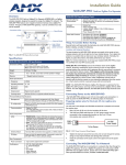
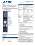
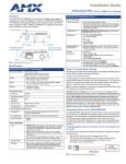
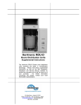
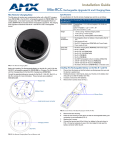
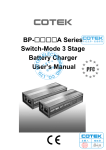
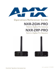
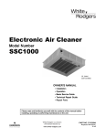
Quick Start Guide
NXR-ZGW/ZRP
Overview
NetLinx ZigBee Gateway and Repeater
NXR-ZGW and NXR-ZRP Specifications (Cont.)
The NXR-ZGW (FG5791-01) is an Ethernet to ZigBee wireless gateway. The
NXR-ZGW features a 10BaseT, half duplex Ethernet port capable of Power over
Ethernet (PoE), 16 Mbytes of Flash, 16 Mbytes of SDRAM, and a ZigBee
module, and is controlled via a web server interface.
ID Button
The NXR-ZRP (FG5791-02) is a ZigBee wireless repeater.
• NXR-ZGW: When used in conjunction with NetLinx Studio,
sets the device and system numbers for the NXR-ZGW.
Press and hold for approximately 30 seconds to return the
NXR-ZGW to factory default settings.
• NXR-ZRP: Press and hold for approximately 10 seconds
to return the NXR-ZRP to factory default settings.
Rear Components:
Connection LEDs
Power connector
• 2-pin 3.5mm captive-wire connector
• NXR-ZGW: Power Over Ethernet (PoE) - powers the
device through the CAT5 cable. Both Power and Data can
be transmitted simultaneous through the CAT5 cable
when using the appropriate equipment.
Ethernet port
10BaseT Modular (RJ-45) connector - connects the NXRZGW to your LAN and/or to connect your third party device
to the LAN when the NXR-ZGW is used as a gateway.
PWR/STATUS
LAN
RF
ANT
(Front)
ID
Antenna Mount
ID Button
10BaseT Modular
(RJ-45) connector
2-pin 3.5mm captive
wire power connector
ETHERNET
PoE
Certifications:
12VDC
PWR
NXR-ZRP:
• FCC ID: CWU-ZRD
• IC ID: 5088A-ZRD
• CE
• IEC-60590
• TELEC
(Rear)
FIG. 1 The NXR-ZGW Device (front and rear)
Specifications
NXR-ZGW (FG5791-01) and NXR-ZRP (FG5791-02) Specifications
NXR-ZGW:
• FCC ID: CWU-ZGW
• IC ID: 5078A-ZGW
• CE
• IEC-60950
• TELEC
Operating/Storage
Environments:
• Operating Temperature: -30°C (-22°F) to 70°C (158°F)
• Relative Humidity: 5% to 85% non-condensing; intended
for indoor use only
Power:
• 10.5 - 18 VDC; (13.5 VDC nominal operation voltage)
• NXR-ZGW: Power over Ethernet (PoE) Class 2
Dimensions (HWD):
Memory:
NXR-ZGW only:
NXR-ZRP only:
• 16 Mbytes of Flash
• 16 Mbytes of SDRAM
• 1 Megabit external memory
0.91” x 2.50” x 3.42”
(23.01 mm x 63.50 mm x 86.96 mm)
Note: depth does not include antenna
Weight:
• NXR-ZGW: 0.35 lbs (158.75g)
• NXR-ZRP: 0.25 lbs (113.39g)
Frequency
2.4GHz
Included
Accessories:
Operating channels
11 - 26
Modulation
technique
DSS
• Rubber feet
• Velcro mounting strip
• 2.4GHZ, MONO, RSMA, 3.5IN, 2.0DBI Antenna
(70-0012-SA)
• Power Supply (24-5791-SA)
Other AMX Products:
Output power
Region/country specific
Coverage area
165 feet (50.2m)
•
•
•
•
•
Radio Specifications:
Firmware/Software Specifications:
Management
Built-in browser-based management with User Name/
Password authentication (NXR-ZGW only)
IP configuration
Static IP or DHCP client (default is static, 192.168.1.140)
Communications
• ZigBee
• TCP/IP
• The NXR-ZRP communicates with a Netlinx master via a
NXR-ZGW.
Front Components:
LEDs
Antenna Mount
• PWR/STATUS - (NXR-ZGW) A green LED that blinks to
indicate the device is installed and communicating
properly. Power ON, but no master connection, is
indicated with a solid light, Power OFF is indicated with no
light. (NXR-ZRP) Power ON is indicated with a solid light.
Power OFF is indicated with no light.
• LAN - (NXR-ZGW) A green LED indicates an Ethernet
connection is established. The LED blinks to indicate both
sending and receiving information via Ethernet.
• RF - The LED is solid when end devices are connected;
end devices not connected is indicated with no LED light;
the LED blinks to indicate activity.
• ICSP - (NXR-ZRP) The LED is solid when ICSP
connection is in place with the NetLinx master.
A reverse SMA connection that supports a 2.4GHz antenna.
Mio Modero R-3 Remote (FG148-03)
Mio Modero R-4 Remote (FG148-04)
NXA-WAP 2403A 3 dBI Antenna (FG2255-20)
NXA-WAP 2405A 5.5 dBI Antenna (FG2255-21)
NXA-WAP 2413A Mounting Bracket (FG2255-24)
NOTE: Connection to the Repeater device from either the NXR-ZGW or the Mio
Modero® R-3 or R-4 requires download and installation to the repeater of ZigBee
Module firmware version 1.01.12, available from www.amx.com.
Things To Consider Before Starting
Several factors will help decide the best place to install NXR-ZGW and
NXR-ZRP devices. Before installing, consider the following:
Location and Antenna Direction
The best location for NXR-ZGW and NXR-ZRP devices are usually in the center
of your wireless network, with line of sight to all of your mobile devices. Try to
place the antenna in a position that can best cover your wireless network.
Normally, the higher you place the antenna, the better performance you receive.
Note: For minimal interference, try to keep any installed NXR-ZGW at least 10’
(3.048m) from any WiFi access points.
Connecting the Optional Accessory Antennas
Several accessory 2.4GHz antennas are available for use with NXR-ZGW and
NXR-ZRP devices. Each of these antennas is uniquely suited to meet a wide
variety of installation requirements.
NOTE (Mio R-3 or R-4 Users): Due to the wireless nature of the ZigBee
network, temporary interference (such as leaving a room or large objects
passing between the controller and its gateway device) may prevent a command
from reaching the NetLinx master. If this happens while increasing volume,
the master may receive the command to increase the volume but not the
command to stop increasing it. Therefore, programmers should consider
setting safeguards for volume control, either established volume limits or
timeouts with the NetLinx master or more interactive adjustment from the
remote (i.e., direct volume control), to prevent issues with lost commands.
3.
Connecting Power to the NXR-ZGW and NXR-ZRP
4.
5.
6.
The NXR-ZGW receives power via either PoE or 2-pin 3.5 mm mini-captive
wire connection, the NXR-ZRP only utilizes the 2-pin 3.5 mm mini-captive wire
connection. If PoE is selected, the NXR-ZGW will draw power through the
CAT5 Ethernet cable at approximately 60mA at 48V. If the 2-pin 3.5 mm
mini-captive wire connector is selected, the following steps are necessary:
Setting the ICSP connection to the Netlinx master
1.
Preparing captive wires for the 2-pin 3.5 mm mini-captive
wire connector
2.
You will need a wire stripper and flat-blade screwdriver to prepare and connect
the captive wires.
3.
1.
2.
4.
5.
Strip 0.25 inch (6.35 mm) of wire insulation off all wires.
The PWR and GND cable from the 12 VDC power supply must be
connected to the corresponding location on the 2-pin 3.5 mm
mini-captive wire connector (FIG. 2).
PWR +
GND -
12 VDC
Power Supply
To the Device
FIG. 2 12 VDC Power Connector Wiring Diagram
3.
4.
Tighten the clamp to secure the two wires. Do not over-torque the screws;
doing so may strip the threads and damage the connector.
Verify the connection of the 2-pin 3.5mm mini-captive wire to the power
supply.
Click the radio button for either Dynamic or Static. If your network has a
DHCP server you may select 'Dynamic', and the gateway will request IP
information from the server.
If configured for Static, type the IP address in the field provided.
If necessary, type the subnet mask and gateway in the fields provided.
Click Accept.
In the menu at the top of the NXR-ZGW Browser-based Configuration
Manager, select NetLinx Settings under the section Configuration.
Enter the device number to be assigned to the NXR-ZGW in the Device
Number field.
Enter the IP address of the master that the NXR-ZGW is to connect with
in the Master IP/URL field.
Click Accept.
In the The system will need to reboot for changes to take effect window,
click OK.
Setting a new username and password
1.
2.
3.
4.
5.
Select User Settings under the section Configuration.
In the text field next to New Username, type the new name.
In the text field next to New Password, type the new password.
Confirm the password in the field Re-type Password.
Click Accept.
Personal Area Network
Enabling and disabling the wireless network
1.
2.
In the menu on the top of the NXR-ZGW Browser-based Configuration
Manager, select Network under the section Pan.
Click the radio button next to Enable to enable the wireless network or
select Disable to disable the network.
Click Accept.
Connecting the NXR-ZGW to a LAN
3.
Insert one end of the CAT5 Ethernet cable into the rear RJ-45 jack and connect
the other end of the same cable to a master or to a switch connected to a
master.
Connecting an NXR-ZRP to the network for the first time
Setting Up A Network
2.
3.
4.
5.
6.
After you have established the location of the gateway, connected it, provided
power, and placed the device in either a rack or wall installation, you can then
begin configuring the NXR-ZGW and adding an NXR-ZRP and
ZigBee-compatible devices to the network.
1.
2.
3.
4.
5.
6.
Confirm the NXR-ZGW is receiving power by checking the PWR LED
shown in FIG. 1.
Using a PC connected to your NetLinx system, navigate to the NXR-ZGW
Browser-based Configuration Manager in your preferred Web browser.
The default IP address for the NXR-ZGW is 192.168.1.140.
Go to the NetLinx setup page and configure the NXR-ZGW to
communicate with the master.
Go to the PAN page and change the PAN ID.
Turn on AMX ZigBee-compatible devices one at a time, e.g., Mio R-3, Mio
R-4 or NXR-ZRP. Select the correct new PAN ID.
For devices that do not have displays (NXR-ZRP), or not enough display
to select the PAN ID to join a network, place each device one at a time
near the gateway, turn one of them on, and configure it using the gateway
web pages before turning on the next one. Then use the PAN pages to
change the devices over to a new PAN ID.
This method may also be used if you do not want to go to each ZigBee
compatible device to set the PAN ID; however, once each device is set,
the change must be done to the gateway itself. It may be necessary to
cycle power on each device for them to come online.
NXR-ZGW Configuration Manager Pages
To access the Configuration Manager pages, enter the IP address of the
NXR-ZGW into your web browser.
1.
7.
8.
9.
10.
In the menu on the top of the NXR-ZGW Browser-based Configuration
Manager, select Network under the section Pan.
In the PAN ID field, enter the default PAN ID for the repeater: 3FFF.
Click Accept.
Select the Connections tab; the repeater should appear on the router.
Click on the EUI-64 link to open the Device Details page.
In the PAN ID field, enter the desired PAN ID for the repeater within the
network.
Click Update Settings.
Repeat steps 1-6 for each repeater to be added to the network.
Select the Network tab under the section Pan and enter the desired PAN
ID in the Change PAN ID field.
Click Accept.
Utilities
Allowing firmware updates to devices
1.
2.
3.
4.
5.
In the menu on the top of the NXR-ZGW Browser-based Configuration
Manager, select Device Firmware under the section Utilities.
Choose the device to be updated by its EUI-64 number.
To allow updates to individual devices, click the button next to the
device’s EUI-64 number in the Allow Updates column. The page will
automatically refresh, displaying the device’s new status.
To update all of the devices on a network, click All On or All Off in the
Allow Updates column to allow or block upgrades to all devices on the
network. The page will automatically refresh, displaying the new status of
all network devices.
Some devices cannot have their firmware update status changed; these
devices will continue to read Off even after selecting to allow new
updates.
The default IP address for the NXR-ZGW is 192.168.1.140.
Setting the IP Address
1.
2.
Upon accessing the NXR-ZGW Browser-based Configuration Manager,
the user must enter a username and password. The default entries are
“Admin” and “1988”; changing the password as soon as possible is highly
recommended.
In the menu at the top of the Configuration Manager, select IP Settings
under the section Configuration.
For full warranty information, refer to the AMX Instruction Manual(s) associated with your Product(s).
8/07
©2007 AMX. All rights reserved. AMX and the AMX logo are registered trademarks of AMX.
AMX reserves the right to alter specifications without notice at any time.
3000 RESEARCH DRIVE, RICHARDSON, TX 75082 • 800.222.0193 • fax 469.624.7153 • technical support 800.932.6993 • www.amx.com
93-5791-01
REV: E