1
Owners
Owners Guide
Guide for
for the
the
Bass Amplifier
33Hz
INPUT
GAIN
BASS
HI
BRT
MIDRANGE
FREQUENCY
TREBLE
MASTER
TUBE GAIN
+12dB
0
-15dB
PEAK /
MUTE
LO
80Hz
150Hz
300Hz
600Hz
900Hz
2kHz
5kHz
9kHz
+8dB
POWER
MUTE
EQ
-12dB
ON
LEVEL
-10dB
ON
Ampeg ®® is Proudly Made in America
SVT-3 PRO Bass Amplifier
TABLE OF CONTENTS
Introduction . . . . . . . . . . . . . . . . . . . . . . . . . . . . . .2
Features . . . . . . . . . . . . . . . . . . . . . . . . . . . . . . . .2
Important Safeguards and Precautions . . . . . . . . . .2
The Front Panel Controls and Their Use . . . . . . .3,4
The Rear Panel . . . . . . . . . . . . . . . . . . . . . . . . . .4,5
Some Suggested Settings . . . . . . . . . . . . . . . . . . .6
Rack Mounting . . . . . . . . . . . . . . . . . . . . . . . . . . . .6
Troubleshooting . . . . . . . . . . . . . . . . . . . . . . . . . . .7
System Block Diagram . . . . . . . . . . . . . . . . . . . . . .7
Technical Specifications . . . . . . . . . . . . .back cover
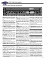
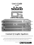
Features
In the world of high performance bass amps, Ampeg’s SVT
amplifiers stand alone. In true Ampeg tradition, the SVT-3 PRO
offers you more power, performance and flexibility than any other
bass amplifier in its class. Below are some of the outstanding features of your new amplifier - features which set it apart from the
competition!
• 5-POSITION MIDRANGE SELECTOR: Take your pick from the five center frequency points available to get just the right midrange voice (page 3).
• TUBE GAIN: Control the dynamics of tonal response characteristics from
the power amp; from punchy to compressed (page 3).
• 9-BAND GRAPHIC EQ: Use as a “second channel” for bass solos, or to
shape your sound to your own exacting standards. An independent level
control lets you adjust the Graphic EQ volume (page 3).
• TRANSFORMER BALANCED LINE OUTPUTS: Independent level control. One balanced XLR and one balanced/unbalanced 1/4” jack to patch
into house consoles, mixing boards, or external power amplifiers (page 4).
• EFFECTS LOOP: Connect your effects here for increased intensity and
quieter operation (page 5).
• POWER AMP IN AND PREAMP OUT: A separate preamp may be connected to the Power Amp In jack, and the Preamp Out jack may be connected to a slave amp. (page 5).
An Introduction to your new Ampeg
SVT-3 PRO Bass Amplifier
The harmonically rich sound and legendary performance of
the AMPEG SVT are redefined in the SVT-3 PRO. This compact yet dynamically powerful bass amplifier delivers a searing 450 watts of unsurpassed quality, offering the classic
vibrance of tubes as well as contemporary features.
All of the features and controls of your SVT-3 PRO are covered in detail within the pages of this owner’s guide. We recommend that you go over them before you use the amplifier.
Important Safeguards and Precautions
All Ampeg products are designed for continuous safe operation, as long as common sense is used and steps are taken to help
avoid certain problems. Abiding by the following rules can help prevent damage to your amplifier, yourself and others.
• The amplifier is equipped with a three-pronged AC power cord. To reduce the risk of electrical shock, NEVER remove or otherwise
attempt to defeat the ground pin of the power cord.
• Connect the amplifier ONLY to a properly grounded AC outlet of the proper voltage for your amp.
• Avoid sudden temperature extremes, rain and moisture. Also, avoid sudden and intense impact. (If the unit has been subjected to any
of the preceding abuses, have it looked at by an authorized service center.)
• NEVER set the amplifier on a support that might give out under its weight.
• Whenever using tall or stacked speaker cabinets, use them ONLY on a level surface. NEVER set tall or stacked cabinets on a surface
with more than a five degree incline since tipping or falling could occur, possibly causing serious injuries.
• Always keep the total speaker impedance at or above the rated load.
• Unplug the amplifier before cleaning it. NEVER spray liquid cleaners onto the amplifier. Wipe it with a slightly dampened, lint-free cloth
to remove dirt and film.
• Don’t use the amplifier if it has sustained damage to the chassis, controls, or power cord. Refer the unit to an authorized service center for inspection.
• Amplifiers capable of producing high volume levels are also capable of inflicting permanent hearing loss or damage, if the exposure to
such levels is prolonged. Such damage is progressive and irreversible!
CAUTION
ATTENTION
VORSICHT
RISK OF ELECTRIC SHOCK
DO NOT OPEN
RISQUE D'ELECTROCUTION
NE PAS OUVRIR
ELEKTRISCHE SCHLAGGEFAHR
NICHT OFFENEN
CAUTION: TO REDUCE THE RISK OF ELECTRIC SHOCK,
DO NOT REMOVE COVER.
NO USER-SERVICEABLE PARTS INSIDE.
REFER SERVICING TO QUALIFIED SERVICE PERSONNEL.
ATTENTION: POUR REDUIRE D'ELECTROCUTION NE PAS
ENLEVER LE COUVERCLE. AUCUNE PIECE INTERNE N'EST REPRABLE
PAR L'UTILISATEUR. POUR TOUTE REPARATION, S'ADRESSER A UN
TECHNICIEN QUALIFIE.
VORSICHT: ZUR MINIMIERUNG ELEKTRISCHER SCHLAGGEFAHR NICHT
DEN DECKEL ABENHMEN. INTERNE TEILE KONNEN NICHT VOM
BENUTZER GEWARTET WERDEN. DIE WARTUNG IS QUALIFIZIERTEM
WARTUNGSPERSONAL ZU UBERLASSEN.
THIS EQUIPMENT HAS BEEN DESIGNED AND ENGINEERED TO PROVIDE SAFE AND RELIABLE OPERATION. IN ORDER TO PROLONG THE LIFE OF THE UNIT AND PREVENT ACCIDENTAL DAMAGES OR INJURY, PLEASE FOLLOW THESE PRECAUTIONARY GUIDELINES:
WARNING: TO REDUCE THE RISK OF ELECTRIC SHOCK, DO NOT OPEN CHASSIS; DO NOT DEFEAT OR REMOVE THE GROUND PIN OF THE POWER CORD; CONNECT ONLY TO A PROPERLY GROUNDED AC POWER OUTLET.
CAUTION: TO REDUCE THE RISK OF FIRE OR ELECTRIC SHOCK, DO NOT EXPOSE THIS EQUIPMENT TO RAIN OR MOISTURE.
CAUTION: NO USER-SERVICEABLE PARTS INSIDE. REFER SERVICING TO QUALIFIED SERVICE PERSONNEL.
CAUTION: OUR AMPLIFIERS ARE CAPABLE OF PRODUCING HIGH SOUND PRESSURE LEVELS. CONTINUED EXPOSURE TO HIGH SOUND PRESSURE LEVELS CAN CAUSE PERMANENT
HEARING IMPAIRMENT OR LOSS. USER CAUTION IS ADVISED AND EAR PROTECTION IS RECOMMENDED IF UNIT IS OPERATED AT HIGH VOLUME. The chart below shows the U.S.
Government Occupational Safety and Health Administration (OSHA) regulations which were in effect at the time of this publication for permissible noise exposure, per 29CRF1910, Table G-16.
SOUND LEVEL dBA
SLOW RESPONSE
DURATION PER DAY
IN HOURS
SOUND LEVEL dBA
SLOW RESPONSE
DURATION PER DAY
IN HOURS
90
92
95
97
100
8
6
4
3
2
102
105
110
115
1-1/2
1
1/2
1/4 or less
According to OSHA, any exposure in excess of those listed above could result in some hearing loss.
2
EXPLANATION OF
GRAPHICAL SYMBOLS:
"DANGEROUS VOLTAGE"
= "DANGER HAUTE TENSION"
"GEFAHLICHE SPANNUNG"
"IT IS NECESSARY FOR THE USER TO REFER TO THE INSTRUCTION MANUAL"
= "REFERREZ-VOUS AU MANUAL D'UTILISATION"
"UNBEDINGT IN DER BEDIENUNGSANLEITUNG NACHSCHLAGEN"
SVT-3 PRO Bass Amplifier
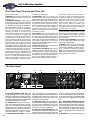
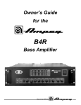
The Front Panel Controls and Their Use
33Hz
INPUT
GAIN
BASS
MIDRANGE
FREQUENCY
TREBLE
MASTER
TUBE GAIN
80Hz
150Hz
300Hz
600Hz
900Hz
2kHz
5kHz
9kHz
+12dB
+8dB
0
-15dB
1
2
34
EQ
LO
PEAK /
MUTE
5
6
POWER
MUTE
HI
BRT
7
8
9
10
11
12
LEVEL
-12dB
-10dB
ON
13 14 15 16
1. INPUT: The signal output from an instrument
(active or passive) or a line level signal may be connected here by means of a shielded instrument
cable.
2. BRIGHT: This switch, when depressed, adds a
more lively top end response to the input signal.
3. -15dB: This switch, when depressed, attenuates
the input signal by 15dB. Attenuation allows the Gain
control (#5) to be used over a larger portion of its
range. If clipping is indicated with the Gain control
way down, attenuation is needed.
4. PEAK LED: This LED flashes when the signal
level into the preamp (excluding the graphic EQ)
approaches clipping. Adjust the Gain control (#5) until
a strong signal from your instrument causes this LED
to flicker.
NOTE: If the LED flashes frequently with the Gain at
a low setting, use the -15dB switch (#3) to attenuate
the input signal and readjust the Gain.
5. GAIN: This serves as the input level control for the
amplifier. For the best signal to noise ratio set this
control so the Peak LED (#3) flashes when you strike
a string fairly hard.
6. ULTRA HIGH: This switch, when depressed,
enhances the amount of high frequency output by
6dB at 5kHz.
7. ULTRA LOW: This switch, when depressed,
greatly enhances the amount of low-end bass tones
which you can feel and hear, especially the low E and
low B strings (of a 5-string bass).
8. BASS: This is the primary low frequency control
which allows for 12dB of cut or boost at 50Hz.
9. MIDRANGE: This is the primary midrange control
which allows for 15dB of cut or boost at the center
frequency selected by the Frequency control (see
#10).
10. FREQUENCY: This control allows you to select
the center frequency for the midrange control, giving
you a choice of five “voices” for the midrange. The
numbers correspond to the following center frequencies: 1=220Hz, 2=450Hz, 3=800Hz, 4=1.6kHz,
5=3kHz.
11. TREBLE: This is the primary high frequency
control which allows for 19dB of cut or 14dB of boost
at 5kHz.
12. MASTER: Set the overall output level of the
amplifier with this control.
13. TUBE GAIN: The tube gain control varies the
high voltage supply to the power amp tubes. This
allows a variety of tonal response characteristics from
the power amp and replaces the limiter found on typical solid state power amps. At “10” the voltage is at
maximum, providing a dynamic, highly responsive
tone. At “0” the voltage is at minimum, offering a thickened, more compressed tone. This tone can also be
distorted, depending on volume level. In between settings are best for preventing harsh distortion when
driving the power amp to its limits. The effect of this
control increases from moderate to dramatic as the
power amp is driven harder.
NOTE: When adjusting the tube gain control from
“10” to “0” rapidly, a low frequency hum as well as
muting of the output signal occur simultaneously. This
is due to shifting of the DC bias point of the tubes, and
is no cause for concern. Adjusting the control quickly
from “0” to “10” brings a moderate delay due to the
power supply capacitors charging.
14. MUTE: Use this switch to mute all outputs except
the Tuner Out (rear panel #28). The footswitch can
1. ENTRADA: Conecte aquí su guitarra de bajos
utilizando un cable blindado para instrumentos.
2. BRILLANTE: Este interruptor, cuando se encuentre ADENTRO, añade a la señal de entrada una
respuesta más viva en la parte alta. Usted puede
experi-mentar el uso de diferentes posi-ciones del
EQ con este interruptor.
3. -15dB: Este interruptor, cuando se encuentre
ADENTRO, atenuará en 15dB la señal de entrada.
Si su bajo tiene circuitos electrónicos activos, usted
tal vez quiera usar este interruptor.
4. DIODO LED DE PICOS: Este LED se iluminará
cuando el nivel de preamplificación esté cerca del
nivel de aplanamiento "clipping", lo que indicaría una
posición de ganancia óptima.
5. GANANCIA: Esto controla la ganancia del preamplificador.
6. ULTRA AGUDOS: Cuando se oprime hacia
ADENTRO, este interruptor realza la cantidad de la
salida de frecuencias altas en 6dB a 5kHz.
7. ULTRA GRAVES: Al oprimirse este interruptor
hacia ADENTRO, se realza en gran forma la cantidad de tonos bajos de la parte grave que usted
puede sentir y oír, en especial de las cuerdas de E
bajo y B bajo (en un bajo de 5 cuerdas).
8. BAJOS: Es el control primordial para las frecuencias bajas. Permite 12dB de recorte (totalmente a la
izquierda) ó refuerzo (totalmente a la derecha) a
50Hz. La salida de frecuencias graves queda plana
en la posición central.
ON
17
18
19
20
also control muting, if the Mute switch on the front
panel is left in the “out” position. (The front panel
switch is still active with the footswitch connected.
This is excellent for tuning your bass with an electric
tuner without having to adjust any levels to turn down
your sound.)
15. GRAPHIC EQ: This switch, when depressed,
enables the 9-band Graphic EQ (see #17 & #18). A
footswitch overrides this switch.
16. ACTIVE LED: This LED illuminates when the EQ
is on.
17. 9-BAND GRAPHIC EQ: These sliders control
the output frequencies indicated above each control.
The center position of each control is flat (no boost or
cut).
The Graphic EQ can be used in two ways: 1) To fine tune
your sound, make small adjustments at the desired frequencies and leave the EQ on throughout the entire session. (This is great for adapting to varying room acoustics
when going from club to club, etc.) 2) For a completely different sound, make larger adjustments and only activate the
EQ when you want a “second channel” sound (such as during bass solos).
18. LEVEL: This slider is the output volume control for
the Graphic EQ and only affects the signal when the
EQ is engaged. If the EQ’d signal is too soft, slide the
Level control up; if it’s too loud, slide this control down.
19. ON LED: This LED illuminates when the Power
is ON.
20. POWER: This heavy-duty rocker switch applies
the power to the amplifier: the amp is ON when the
top of the switch is depressed, OFF when the bottom
of the switch is depressed.
NOTE: There is a delay during power up until the protection relay enables the power amplifier output.
9. RANGO MEDIANO: Es el control primordial en el
rango mediano. Permite 15dB de recorte (totalmente
a la izquierda) ó refuerzo (totalmente a la derecha) a
la frecuencia central que se haya seleccionado en el
control de Frecuencias (véase #10). La salida del
rango mediano está plana en la posición central.
10. FRECUENCIA: Le permite seleccionar la frecuencia central para el control del rango mediano, lo
que le da la opción de cinco "voces" para el rango
mediano. Las frecuencias correspondientes son:
1=220Hz, 2=450Hz, 3=800Hz, 4=1.6kHz, 5=3kHz.
11. AGUDOS: Es el control primordial para las frecuencias altas. Permite 19dB de recorte (totalmente
a la izquierda) ó 14dB de refuerzo (totalmente a la
derecha) a 5kHz. La salida de frecuencias altas es
3
SVT-3 PRO Bass Amplifier
The Front Panel Controls and Their Use
plana en la posición central.
12. MAESTRO: Esto controla el nivel general de la
salida del amplificador. Utilice este control junto con
la Ganancia (#5).
13. GANANCIA DE BULBOS: El control de ganancia de los bulbos varía el suministro de voltaje alto a
los bulbos del amplificador de potencia. Esto permite
una variedad de características de respuestas de
tonos del amplificador de potencia y ocupa el lugar
del limitador que se encuentra en amplificadores
típicos de estado sólido. En "10" el voltaje se
encuentra en su máximo, lo que provee un tono
dinámico altamente sensible. En "0" el voltaje está
en su mínimo, lo que ofrece un tono espeso y más
comprimido. Este tono también se puede distorsionar, dependiendo del nivel del volumen. Las posiciones intermedias son mejores para evitar una distorsión áspera al impulsar el amplificador de potencia hasta su límite. El efecto del control aumenta
desde lo moderado hasta lo dramático conforme el
amplificador de potencia se impulse cada vez más
fuerte. NOTA: Cuando ajuste rápidamente el control
de la ganancia de los bulbos desde "10" hasta "0",
ocurrirán en forma simultánea un zumbido de frecuencia baja lo mismo que un silenciamiento de la
señal de salida. Esto se debe al cambio en la posición del punto de polarización ("bias") de CD en los
bulbos, y no es razón para preocuparse. El ajuste
rápido del control desde "0" hasta "10" trae una
demora moderada debido a la carga de los capaci-
tores del suministro de energía.
14. SILENCIADOR: Utilice este interruptor para
silenciar todas las salidas excepto la Salida de
Afinación (panel posterior #28). El interruptor de pie
también puede controlar el silenciamiento si el interruptor Silenciador del panel delantero se ha dejado
en la posición de "afuera". (El interruptor del panel
delantero aún queda activo cuando el interruptor de
pie se encuentre conectado.) Este interruptor es
excelente para afinar su bajo con un sintonizador
eléctrico sin tener que ajustar ninguno de los niveles
para disminuir su sonido.
15. EQ GRAFICO: Este interruptor habilita al EQ
Gráfico de 9 bandas (véanse #17 & #18). El sonido
de su bajo sólo se verá afectado por los ajustes en
los controles deslizantes (cursores) del EQ cuando
este interruptor se encuentre hacia ADENTRO ó se
haya oprimido el interruptor de pie. El control del
interruptor de pie anula al (tiene preferencia sobre el)
interruptor del panel delantero.
16. DIODO (LED) ACTIVO: Este se iluminará cuando el EQ se encuentre prendido.
17. EQ GRAFICO DE 9 BANDAS: Estos controles
deslizantes (cursores) le permiten ajustar las frecuencias de salida que se muestran sobre cada control. La posición central de cada control está plana;
el deslizamiento del control hacia arriba incrementará el nivel de salida de aquella frecuencia; el
deslizamiento del control hacia abajo lo reducirá.
El EQ Gráfico se puede usar de dos maneras: 1)
Para afinar su sonido, hacer pequeños ajustes en
las frecuencias deseadas y dejar prendido el EQ
durante toda la sesión. (Esto es muy bueno para
adaptarse a variaciones en la acústica del salón
cuando vaya de un club a otro, etc.); 2) Para conseguir un sonido diferente por completo, hacer
ajustes más grandes y sólo activar el EQ cuando
usted quiera un sonido de "segundo canal" (como
por ejemplo durante solos de bajo).
18. NIVEL: Este es el control del volumen de la salida para el EQ Gráfico y solamente afecta a la señal
cuando el EQ se encuentre activado. Si la señal del
EQ está demasiado suave, deslice el control de
Nivel hacia arriba; si está demasiado fuerte traiga el
control hacia abajo.
19. DIODO "LED" DE PRENDIDO: Este LED brillará
con un color verde cuando el interruptor de Energía
(#20) se encuentre PRENDIDO.
20. ENERGIA: Este interruptor de servicio pesado
tipo vaivén aplica la energía eléctrica al amplificador;
el amplificador se PRENDE en la posición hacia arriba (1), y se APAGA en la posición hacia abajo (0).
NOTA: Hay una demora durante la energía hacia
arriba hasta que el relevador de protección habilite la
salida del amplificador de potencia.
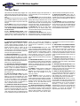
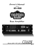
The Rear Panel
21
22
23
24
AC OUTLET
300 WATTS MAX.
MODEL:
SERIAL:
LINE:
WATTS:
26
TRANSFORMER BAL.
SVT-3PRO
T3PDH401222
120 V ~ XX
Hz
1000 MAX
MADE IN THE U.S.A.
BY SLM ELECTRONICS
1400 FERGUSON AVE.
ST. LOUIS, MO. 63133
25
PULL
GROUND
LIFT
SPEAKER OUTPUTS
PRE
28
LINE OUTPUT
POST
LEVEL
275 WATTS @ 8 OHMS
450 WATTS @ 4 OHMS
4 OHM MIN. LOAD
27
BALANCED
BALANCED/
UNBALANCED
TUNER OUT
EFFECTS LOOP
110/115V: 250V
T10A SLO BLO
230V: 250V
T5A SLO BLO
CAUTION: TO
REDUCE THE RISK
OF FIRE, REPLACE
FUSE WITH SAME
TYPE AND RATING.
AC LINE IN
ATTENTION:
CAUTION
UTILISER UN FUSIBLE DE RECHANGE
DE MEME TYPE.
RISK OF ELECTRIC
SHOCK - DO NOT OPEN
29
30
21. AC OUTLET (DOMESTIC UNITS ONLY): This
unswitched outlet lets you connect any AC powered
device (such as an effects unit or an electronic tuner) up
to a maximum of 300 watts. The jack is “hot” whenever
the amplifier is plugged into a live AC outlet, regardless
of the setting of the amplifier’s Power switch.
22. SPEAKON JACK: Use of this heavy-duty connector is recommended when playing at full output
levels, due to its incredibly high current handling
capability. Connect the amplifier to your speaker
cabinet(s) using heavy gauge speaker cables terminated with the appropriate connectors. The pin connections for this jack are 1+ = positive, 1– = negative.
23. RACK SUPPORT FASTENER: For the most
4
AVIS:
RISQUE DE CHOC
ELECTRIQUE
NE PAS OUVRIR
TO REDUCE THE RISK
OF FIRE OR ELECTRIC
SHOCK, DO NOT EXPOSE THIS EQUIPMENT
TO RAIN OR MOISTURE.
POWER AMP
IN
PREAMP
OUT
RETURN
SEND
FOOTSWITCH
32
33
34
35
36
31
secure rack installation it is recommended that a
supplemental support be fabricated and fastened to
the amplifier via this threaded insert. Use a 1/4-20
threaded bolt that will not protrude more than 1/2”
into amplifier to connect the strap.
24. LINE OUTPUT LEVEL: This control adjusts the
output level at both Line Output jacks (#26 and #27).
This control works independently from the front
panel Master control. Pull this knob to engage the
Ground Lift, if necessary to eliminate hum.
25. LINE OUTPUT SELECTOR SWITCH: You can
select either Pre or Post EQ for the signal at the Line
Out jacks (#26 and #27) with this switch. With this
switch in the OUT position, the signal at the jacks will
be Pre-EQ. (This is a direct output not affected by
any EQ or boost settings.) When this is depressed,
the signal is Post-EQ and is controlled and modified
by the tone controls, Graphic EQ and the effects
loop.
26,27. TRANSFORMER BALANCED LINE OUTPUTS: These jacks supply a balanced/unbalanced
preamp output signal for connecting to a house mixing board, recording console or external amplifiers
with balanced inputs. The signal can either be set to
Pre- or Post-EQ with the Selector switch (#25) and
its level is controlled by the Line Out Level control
(#24).
28. TUNER OUT: This jack supplies the only live
SVT-3 PRO Bass Amplifier
The Rear Panel
output when the mute switch (#14) is engaged. This
allows for silent tuning through an electronic tuner or
killing the house send with a monitor mixer send still
active.
29. FUSE: The fuse protects the unit from damage
due to overload conditions or AC power line surges.
If the fuse blows, replace it only with the same size
and type.
30. AC LINE IN: Firmly insert the supplied AC
power cord into this socket until it is fully seated.
Plug the male end of the cord into a grounded AC
outlet. DO NOT DEFEAT THE GROUND PRONG
OF THE AC PLUG!
31. 1/4” SPEAKER OUTPUT JACKS: These
mono 1/4” jacks (wired in parallel) offer you a convenient method of connecting the amplifier to your
speaker(s) using cables terminated with 1/4”
plugs. (Whenever playing at full output levels, it is
recommended that you use the Speakon jack –
see #22).
32. POWER AMP IN: This jack connects directly
to the internal power amp for use with an external
preamp. When using an external source, connect
the OUTPUT of the source to this jack using a
shielded instrument cable to feed the signal into
the power amp section. The internal signal is disconnected when a plug is inserted into this jack.
33. PREAMP OUT: This jack is a direct preamp
output for use with an external power amp.
Connect the external amp’s input to this jack using
a shielded instrument cable.
34. EFFECTS LOOP RETURN: When using an
external signal processor, connect the OUTPUT of
the effect to this jack using a shielded instrument
cable to feed the processed signal into the unit.
35. EFFECTS LOOP SEND: When using an
external signal processor, connect the INPUT of
the effect to this jack using a shielded instrument
cable to send the post-EQ signal to the effect for
processing.
36. FOOTSWITCH: Connect a dual footswitch to
this jack for remote Mute and EQ On/Off control.
On the stereo 1/4” plug, the tip controls Mute and
the ring controls EQ On/Off. The EQ footswitch
overrides the front panel switch and the Mute function is available from either location.
21. SALIDA DE CA (SOLOMENTE EN ESTADOS
UNIDOS): Esta salida sin interruptor le permite
conectar cualquier dispositivo impulsado por CA
(como por ejemplo una unidad de efectos ó un sintetizador electrónico) hasta un máximo de 300
watts. El "jack" se encuentra activo ("caliente")
cuando quiera que el amplificador esté conectado a
una toma activa de CA, sin importar la posición del
interruptor de energía del amplificador.
22. ENCHUFE DE SPEAKON: Se recomienda el
uso de esto enchufe para uso rudo cuando se toque
a niveles de salida máxima, debido a su increíble
capacidad para manejar corrientes altas. Conecte el
amplificador a su(s) gabinete(s) de bocinas empleando cables de calibre pesado para bocinas terminados con los connectores cerrectos.
23. SUJETADOR DE SOPORTE DE BASTIDOR:
Para lograr la instalación más segura de bastidores,
se recomienda que un soporte suplementario se
fabrique y sujete al amplificador mediante esta
inserción roscada. Use un tornillo roscado de - 20
que no resalte más de 1/2" dentro del amplificador
para conectar la tira.
24. NIVEL DE SALIDA EN LINEA: Este control
ajusta el nivel de la salida en ambos "jacks" de
Salida en Línea, tanto la Equilibrada como la No
Equilibrada (#26 y #27) por medio de este interruptor. Este control trabaja en forma independiente
respecto al control Maestro del panel delantero.
Jale la perilla para activar el Levantamiento de
Tierra, si necesario eliminar el zumbido.
25. INTERRUPTOR SELECTOR DE SALIDA DE
LINEA: Por medio de este interruptor, usted puede
seleccionar ya sea Pre ó Post EQ para la señal en
los "jacks" de Línea Afuera (#26 y #27). Con el interruptor en la posición de AFUERA, la señal en los
"jacks" será Pre-EQ. Esta es una salida directa que
no se ve afectada por ninguna posición de EQ ni de
refuerzo. Con el interruptor hacia ADENTRO, la
señal será Post-EQ y la controlan y modifican los
controles de tono, el EQ Gráfico, y el circuito de
efectos.
26, 27. SALIDAS DE LINEA: Estes “jacks” proporcionan una señal de salida equilibrada/ no equilibrada de preamplificación para conectarla a tablero
mezclador doméstico, consola grabadora, ó amplificadores externos con entradas equilibradas. La
señal se puede fijar ya sea en Pre- ó en Post-EQ
con el interruptor Selector (#25), y su nivel se controla por medio del control de Nivel de Línea Afuera
(#24).
28. SINTONIZADOR AFUERA: Este "jack" provee
la única salida viva cuando el interruptor Silenciador
(#14) esté activado. Esto permite afinar en silencio
mediante un sintetizador electrónico ó bien apagar
el envío general manteniendo activo el envío de un
mezclador monitor.
29. FUSIBLE: El fusible protege a la unidad contra
daños debidos a condiciones de sobrecarga ó
desajustes en la línea de energía de CA. Si el
fusible se quema, sólo repóngalo con otro del
mismo tipo y tamaño.
30. CA ADENTRO: Enchufe con firmeza el
extremo hembra del cable proporcionado de
energía CA dentro de este receptáculo, empujándolo por completo hasta dejarlo asentado firmemente.
Enchufe el extremo macho del cordón a una toma
aterrizada de CA. ¡NO PASE POR ALTO EL
BORNE A TIERRA DE LA CLAVIJA DE CA!
31. "JACKS" DE SALIDA DE 1/4" PARA BOCINAS: Estos "jacks" monofónicos de 1/4" (cableados en paralelo) le ofrecen un método conveniente
para conectar el amplificador a su(s) bocina(s) por
medio de cables equipados con clavijas de 1/4".
(Cuando usted toque a niveles altos de salida ,
recomendamos que utilice la enchufe de Speakon véase #22).
32. AMPLIFICADOR DE POTENCIA ADENTRO:
Esto entra directamente al amplificador de potencia
para usarse con un preamplificador externo.
Cuando utilice una fuente externa, conecte la SALIDA de la fuente a este "jack" usando un cable
blindado para instrumentos para alimentar la señal
a la sección del amplificador de potencia. La señal
interna queda desconectada cuando se inserta una
clavija.
33. PREAMPLIFICADOR AFUERA: Esta es una
salida directa del preamplificador para utilizarse con
un amplificador de potencia externo. Conecte el
amplificador a este "jack" usando un cable blindado
para instrumentos.
34. RETORNO CIRCUITO DE EFECTOS: Cuando
use un procesador externo de señales, conecte la
SALIDA del efecto a este "jack" usando un cable
blindado para instrumentos para alimentar la señal
procesada hacia dentro de la unidad.
35. ENVIO AL CIRCUITO DE EFECTOS: Cuando
use un procesador de señales externo, conecte la
ENTRADA del efecto a este "jack" utilizando un
cable blindado para instrumentos para enviar la
señal post-EQ al efecto para su procesamiento.
36. INTERRUPTOR DE PIE: Conecte un interruptor de pie dual a este "jack" para el control remoto
del Silenciador y el Prendido/Apagado del EQ. En la
clavija estereofónica de 1/4", la punta controla al
Silenciador y el anillo controla el Prendido y
Apagado del EQ. El interruptor de pie del EQ anula
al (tiene preferencia sobre el) interruptor del panel
delantero, y la función del Silenciador está
disponible desde cualquiera de los lugares.
5
SVT-3 PRO Bass Amplifier
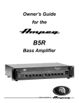
Some Suggested Settings
A Note About The Graphic EQ: The Graphic EQ can be used in two ways:
1) To fine tune your sound, make small adjustments at the desired frequencies and leave the
EQ on throughout the entire session. (This is great for adapting to varying room acoustics when
going from club to club, etc.); 2) For a completely different sound, make larger adjustments and
only activate the EQ when you want a “second channel” sound (such as during bass solos).
ROCK:
GAIN
OUT
-15dB
BASS
MIDRANGE
FREQUENCY
TREBLE
MASTER
TUBE GAIN
BASS
MIDRANGE
FREQUENCY
TREBLE
MASTER
TUBE GAIN
HI
BRT
TO
TASTE
OUT
OUT
LO
PEAK /
MUTE
JAZZ:
GAIN
BRT
HI
OUT
IN
-15dB
TO
TASTE
IN
LO
PEAK /
MUTE
Set at "10" for the cleanest sound.
Set at "5" for moderate softness.
Set at "0" for a very soft feel.
COUNTRY:
GAIN
BRT
HI
OUT
OUT
-15dB
BASS
MIDRANGE
FREQUENCY
TREBLE
MASTER
TUBE GAIN
BASS
MIDRANGE
FREQUENCY
TREBLE
MASTER
TUBE GAIN
IN
LO
PEAK /
MUTE
FUNK “POPPING:”
GAIN
BRT
HI
IN
OUT
-15dB
PEAK /
MUTE
IN
LO
Rack Mounting
When mounting the SVT-3 PRO into a rack, the four bottom feet should be removed to maintain the two rack space height of the amplifier. Be sure to keep the feet and their attachment bolts for future use. If the feet are reinstalled, never use screws which will protrude
farther into the amplifier than the original hardware.
The rack must be a high quality enclosure capable of securely supporting the weight of the amplifier. Tighten the mounting screws
securely through the amplifier’s face plate, into the rack rails. Check the rack and mounting screws occasionally to ensure a continually safe and secure installation.
A 1/4-20 threaded insert is provided on the rear of the amplifier for connection to an additional support bracket. It is highly recommended that this additional support be used when rack mounting the amplifier.
6
SVT-3 PRO Bass Amplifier
Troubleshooting
In the unlikely event that your SVT-3 PRO should malfunction, take a few minutes to troubleshoot it before you call for
service. You can save yourself time and money by doing it yourself, and often the cure for the problem is something quite
simple.
NO SOUND
NO SOUND
LEDs LIGHT
LEDs DON’T LIGHT
Check amp controls, check
for signal from instrument
Check AC outlet
POOR SOUND
OUTLET OK
NO SOUND
Check instrument, cables
SOUND OK
Check power cord,
fuse, power switch
Listen for hum
NO HUM
HUM
Check speaker
Unplug instrument,
touch tip of cable
SOUND OK
NO POWER
Check speaker(s)
Check house fusebox
or circuit breaker
SPEAKER(S) OK,
POOR SOUND
OK
SPEAKER(S)
DEFECTIVE
Replace speaker(s)
SPEAKER OK
NO CHANGE
LOUD HUM
Replace cable
Check bass pickup
NO CHANGE
SOUND OK
POOR SOUND
SOUND OK
SOUND OK
SEE BELOW
SEE BELOW
If the problem isn’t covered above, or if the steps lead you here, then contact your Ampeg dealer for service information. Also, you should refer your amp for servicing if it gets dropped, has liquid spilled into it, or sustains damage to its
power cord (see page 2).
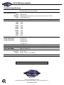
System Block Diagram
BUFFER
TUBES
MOSFETS
SPEAKER
OUT
TUNER
OUT
PRE
BAL./UNBAL.
LINE OUT
INPUT
POST
-15dB PAD
TUBE
GAIN
SPEAKER
OUT
LINE OUT
LEVEL
BALANCED
LINE OUT
POWER AMP
IN
PULL
GROUND LIFT
1+
PREAMP
OUT
PEAK
LED
ULTRA ULTRA
BRIGHT HIGH LOW
12+
2- SPEAKON
JACK
MASTER
VOLUME
EFFECTS
RETURN
FOOTSWITCH
TUBES
MUTE
FOOTSWITCH
EQ
IN
GAIN
BASS
MIDRANGE
TREBLE
FREQUENCY
BUFFER
EFFECTS
SEND
9 BAND
GRAPHIC
EQ
LEVEL
7
SVT-3 PRO Bass Amplifier
Technical Specifications
OUTPUT POWER RATING
450 Watts RMS, 4 ohm load, 120VAC
275 Watts RMS, 8 ohm load, 120VAC
TONE CONTROL RANGE
Bass:
Midrange:
Treble:
GRAPHIC EQ LEVEL
GRAPHIC EQ RANGE
33Hz:
80Hz:
150Hz:
300Hz:
600Hz:
900Hz:
2kHz:
5kHz:
8kHz:
BRIGHT SWITCH
ULTRA HIGH SWITCH
ULTRA LOW SWITCH
±12dB @ 50Hz
±15dB @ selected by Frequency control (220, 450, 800, 1.6k or 3kHz)
+14dB/-19dB @ 5kHz
±10dB
±15dB
±8dB
±8dB
±8dB
±8dB
±8dB
±8dB
±9dB
±10dB
+6dB @2kHz
+6dB @ 5kHz
+2.5dB @ 50Hz
-12dB @ 560Hz
+1.5dB @ 5kHz
75dB typical
Graphic EQ On/Off, Mute On/Off – tip = Mute, Ring = EQ
12AX7 (4), 12AU7 (1)
SIGNAL TO NOISE RATIO
FOOTSWITCH JACK
TUBE COMPLEMENT
POWER REQUIREMENTS
Domestic: 120VAC, 60Hz
Export: 230VAC, 50/60Hz; 100V 50/60Hz
DIMENSIONS
19/17.4”W x 4”H (with feet) x 15.5”D
Ampeg reserves the right to change specifications without notice.
www.ampeg.com
Ampeg is proudly Made in America
©1999 SLM Electronics • 1400 Ferguson Avenue • St. Louis, MO 63133 U.S.A.
P/N 47-614-13 • 07/99