1
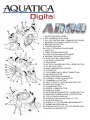
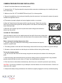
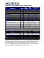
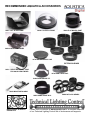
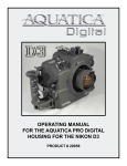
INSTRUCTION MANUAL FOR
AQUATICA AD80
Housing for the Nikon D80
FOREWORD
Thank you for having selected the AQUATICA Pro Digital Camera Housing System
for your underwater photography.
The AQUATICA Pro Digital Housing is the result of a long and continuing relationship with the most demanding underwater
photographers in the world. Each housing is handcrafted, quality checked and pressure tested to 300 feet by a small group of
specially trained individuals, each of whom takes the utmost pride and satisfaction in offering the best underwater camera housing
in the world.
The Aquatica Pro Digital Housing was designed for optimum technical and optical performance and to provide easy and efficient
underwater access to essantials functions and controls of the Nikon D80 DSLR.
This manual assumes that the User is already familiar with the Nikon D80. If not, please read the Nikon instruction Manual before
attempting to use the housing.
With basic care and maintenance, your AQUATICA housing will give you a lifetime of enjoyment and satisfaction in
producing underwater images.
Please read this manual carefully before using your housing for the first time and note that: wherever cited the right hand is your
right when using the housing.
SAFETY PRECAUTIONS
Improper transportation handling or use of this housing might cause a flood or malfunction.
Please read and follow the following precautions:
• Store and transport the housing in a sturdy, shock proof container and avoid travelling with the camera mounted inside the housing
as impact forces especially on the external push buttons will be transferred to the camera.
• When travelling by air, either remove the port or open the housing.
• Never change a port or open the housing in a location where sand or similar foreign material might come in contact with an O-ring.
• Use of accessories or modifications and alterations unauthorized by the manufacturer may result in flooding or poor functioning of
the controls
• Be careful when opening the housing as the pressure buildup inside the housing will exaggerate the force of the latch spring. Keep
fingers away from the path of the latches.
• Whenever changing ports or O-rings, perform a simple seal test with out the camera inside.
• Avoid scratching the acrylic or glass ports and windows.
• Make sure that all ports remain properly attached before rinsing the housing, especially when rinsing without a strobe make sure
the Bulkhead connector is sealed with its plug.
• Never attempt to operate the camera in autofocus mode with the lens mounted focus gear engaged with the housing gear.
• The main O-ring seals should be maintained and cleaned on a regular basis. Read and follow the Care and maintenance instructions
on this manual.
• Ensure that the spring loaded secondary lock is properly engaged to prevent the accidental opening of latches.
1. SHUTTER RELEASE LEVER
2. SUB -COMMAND INPUT KNOB
3. ON / OFF CONTROL SUB -COMMAND INPUT KNOB
4. BULKHEAD FOR FLASH CONNECTOR (2X)
5. BRACKETTING BUTTON
6. FOCUS/ZOOM KNOB
6a. FOCUS / ZOOM RING PINION GEAR
7. GRIPS (X2)
8. LENS LOCK RELEASE LEVER
8a. LENS LOCK RELEASE LEVER SHAFT
9. BAYONNET MOUNTING FLANGE
10. MOUNTING TRAY (REMOVABLE)
11. HOTSHOE CONNECTOR
12. VIEWFINDER
13. AUTOFOCUS MODE SELECTOR / RESET BUTTON
14. AF / AE LOCK LEVER
15. MAIN COMMAND DIAL CONTROL
16. LATCHES (2X)
17. FOCUS AREA / MULTI SELECTOR BUTTONS
18. OK (ENTER) BUTTON
19. REAR VIEW DISPLAY WINDOW
20. PLAYBACK ZOOM / QUAL BUTTON
21. THUMBNAIL / ISO BUTTON
22. HELP / PROTECT / WHITE BALANCE BUTTON
23. MENU ACCESS BUTTON
24. PLAYBACK BUTTON
25. DELETE / FORMAT BUTTON
26. MODE DIAL KNOB
27. METERING MODE SELECTOR / FORMAT BUTTON
28. EXPOSURE COMPENSATION / RESET BUTTON
29. TOP LCD DISPLAY WINDOW
30. ACCESSORY MOUNTING HOLE (1/4” X 20)
31. MODE DIAL WINDOW
32. HOLES (1/4” X 20) FOR ARM’S BASE BRACKETS
33. RUBBER ANTISKID BAD (4x)
34. MOUNTING HOLES (1/4” X 20) FOR STROBE TRAY
35. SACRIFICIAL ANODES (2X)
CONTROLS IN DETAIL:
1. SHUTTER RELEASE LEVER: Pulling the shutter release lever back part way activates the camera meter and auto focus.
Pulling the lever back all the way fires the camera.
2. SUB-COMMAND INPUT / APERTURE KNOB: Rotates clockwise and counterclockwise. Use alone or in combination with other
controls to select or set various camera functions or modes. In “Manual” the exposure mode controls the aperture settings
(see camera manual).
3. ON / OFF / ILLUMINATOR KNOB: Rotate to switch camera on or off or to engage illuminator.
4. BULKHEAD CONNECTOR X2: For Flash Sync Cord. (Nikonos Type).
5. BRACKETING BUTTON: Push to activate the bracketing function, rotate main command knob to desired exposure correction.
6. FOCUS/ZOOM KNOB: Turning allows manual focus of a fixed focal length lens or rotation of the zoom mechanism of a lens.
6a. FOCUS/ZOOM PINION GEAR: Engages and operates the focus or zoom gear attached to the lens.
7. HAND GRIPS (X2): Left and right grip allowing the mounting of strobe arms and accessories.
8 & 8a. LENS RELEASE LEVER: activates the lens release button on the camera allowing easy removal of the lens.
9. BAYONNET MOUNTING FLANGE: allows the mounting of different ports and extension rings on the housing.
10. MOUNTING TRAY: This sliding tray is removable to allow easy access and mounting of the camera.
11. HOT SHOE CONNECTOR: connects the camera to the Flash Bulkhead. Slide this Connector into the camera Hot Shoe. When
detaching do not pull the cord as this might damage the electrical connections.
12. VIEWFINDER: A full view of the illuminated camera viewfinder displays all necessary information. It is removable, and can be
substituted with an Aqua View Finder for even better viewing (see accessories)
13. AF MODE SELECTOR / RESET BUTTON: Press this button to access your auto focus mode selection, also this button when
pressed at the same time as the exposure compensation button (28) will reset the camera settings to its default position.
14. AF / AE LOCK LEVER: Press down lever to engage auto focus or/and auto exposure, see camera manual for the different
options associated to this button.
15. MAIN-COMMAND INPUT KNOB: It rotates clockwise and counterclockwise. It can be used alone or in combination with other
controls to select or set various camera functions or modes. Refer to camera manual for in depth use.
16. LATCHES: Two heavy duty latches are provided with safety locks to protect against accidental opening.
17. FOCUS AREA / MULTI SELECTOR BUTTONS: These buttons have multiple uses. They allow the selection of the focus area,
in the menu mode, they are used to scroll up or down and left to right to choose from your menu selection and they are used in the
delete mode.
18. OK (ENTER): Press to acknowledge selected function.
Controls in detail, continued
19. REAR VIEW DISPLAY WINDOW: allow viewing of menu and images
20. PLAYBACK ZOOM BUTTON / QUALITY: Press to activate the zoom function while reviewing your images in playback mode or
use to select image and/or size quality in shooting mode.
21. THUMBNAIL BUTTON / ISO: Press to display images in “contact sheets” of 4 or 9 images in playback mode or to select ISO
value in shooting mode.
22. HELP / PROTECT BUTTON / WHITE BALANCE: Press to access the help function or to protect selected image from accidental
deletion in playback mode or to access white balance in shooting mode.
23. MENU BUTTON: Press to activate menu, use multi selectors buttons (17) to navigate, press OK button (18) to choose a
selection.
24. PLAYBACK BUTTON: Press to activate the monitor and review images or to select image and/or size quality.
25. DELETE / FORMAT BUTTON: Press to delete images, use multiple selector buttons to select and press the enter button to
delete. Use in conjunction with (27) to format your card.
26. MODE DIAL CONTROL KNOB: rotate clockwise or counter clockwise to select the shooting mode, manual, shutter or aperture
priority and auto program options.
27. METERING MODE / FORMAT BUTTON: Push to select the metering mode, Spot, Center-Weighted or Matrix metering options.
Use in conjunction with (25) to format your card.
28. EXPOSURE COMPENSATION / RESET BUTTON: press to engage the Exposure compensation control [+/-]. Rotate the
Main-Command knob to set the desired exposure compensation value. The value will appear in the Top LCD panel and in the
Viewfinder. This button when pressed at the same time as the AF mode Selector button (13) will reset the camera settings to its
default position.
29. TOP LCD WINDOW: displays essential camera operating data.
30. MOUNTING HOLE: These are 1/4-20 TPI holes that are ready to accept TLC Base Brackets or TLC Base Ball for strobe arms
or accessories.
31. MODE DIAL WINDOW: Gives you visual contact with the mode dial for selection of the proper shooting mode.
32. GRIPS MOUNTING HOLES: Two 1/4” X 20 holes are provided on each grip for mounting strobes trays or accessories.
33. RUBBER ANTISKID PAD: four rubber pads are provided to prevent the housing from skidding on wet surface.
34. MOUNTING HOLES FOR TRAY: Two 1/4”-20 TPI holes are supplied to accept mounting tray and accessories.
35. SACRIFICIAL ANODES: (2X) zinc anodes are installed to protect your housing against salt water corrosion; theses are made
to deteriorate easier than the other strategic part of your housing, hence the name sacrificial anodes. These anodes will need to be
replaced as needed.
FEATURES
The Aquatica Digital housing serie is issued from the world’s most technologically advanced underwater housing lineage, ergonomically
designed to place all the essential camera controls under your finger tips and features the following:
A. A Lens Lock Release control that will activate the lens release button of camera from the outside of the housing.
B. A quick release tray, allowing fast and easy removal of camera.
C. Large ergonomic and easy to operate controls for most of the manual and computerized camera functions.
D. The following controls can be easily manipulated underwater:
- Mechanical shutter release.
- Shutter speed through Main-Command Dial
- Aperture through the Sub-Command Dial
- Focus / Zoom
- LCD panel illumination.
- Top LCD windows information
- Metering system selector
- Auto Bracketing (BKT)
- Exposure mode (Mode)
-.Exposure Compensation
- Focus Area Selector
- ISO sensitivity
- White balance
- Delete button access
- Flash sync mode
E. A complete selection of bayonet mounted ports including an 8” diameter dome, flat ports, extension tubes
and rings to preserve the image quality for most of the Nikkor AF and other popular AF lenses.
F. A complete line of lens gears including Auto/Manual focus selector gears and related accessories.
PREPARATION OF THE HOUSING
1. Attach Grip Bracket to the housing:
The housing comes with two Grips for both right and left hand grips which should be installed on the sides of the housing with the supplied
screws and Allen key. Occasionally remove the grips and lubricate the screws (see Care and Maintenance: of the housing.)
Depending on which strobe system you are using, you can mount the necessary shoes or brackets onto the 1/4”-20 threaded holes on
the top of the hand grips. The AQUATICA TLC strobe arm system is recommended.
There are also two (2) 1/4”-20 threaded holes on the bottom of the housing that can be used for various mounting application trays. As well
there are two holes on top of the rear half of the housing for mounting accessories.
Mount your strobe and connect the sync cord to the housing’s strobe bulkhead. Be sure to read the section titled “Care and Maintenance:
of the O-rings.”
2. Lubricate the Main O-ring Seal:
Before use, remove the Main O-ring seal from its groove on the front half of the housing and carefully verify that the O-ring and the O-ring
groove are free from scratches or foreign material. Lubricate the O-ring with a light coat of silicone grease.
When replacing the O-ring place the entire O-ring over the O-ring groove and start by pushing the O-ring in the corners. Work your way
around the O-ring making sure the O-ring is snugly sitting in the groove.
For proper handling and maintenance of O-rings be sure to read the section titled “Care and Maintenance: of the O-rings.”
PREPARATION OF THE PORTS
1. Select the correct port:
Depending on whether you’ve decided to shoot macro or wide angle photography, you will be installing either the
flat Macro Port (product # 18426), 8” Dome Port (Product # 18405) or 9.25” Glass Dome port.
Refer to the lens selection chart on page 14 for the recommended port .
Or visit our web site www.aquatica.ca for the latest updated chart of lenses, port and accessories.
EXTENSION RINGS
Macro Port Extension Rings: the Macro Port will accept the AF Micro-Nikkor 60mm lens If you intend to use a
longer lens such as the 105mm or 200mm Micro Nikkor you will require an extension rings that fit between the
Macro Port and the housing to provide the extra space necessary for the longer lens.
Dome Port Extension Rings : an extension ring might be needed to optimise the optical performance when
using a wide angle or zoom lens.
In order to reduce glare, maximize contrast and offer physical protection to the dome, the use of a dome shade
(product # 18480 for fisheye shade, and #18482 for wide angle shade) for the 8” dome is recommended.
Refer to the lens selection chart on page 14 for the proper extension ring if needed.
Or visit our web site www.aquatica.ca for the latest updated chart of lenses, port and accessories.
2. Clean the port:
Dirt, grease or fingerprints on the port especially on the inside, can adversely affect the quality of the image.
Acrylic ports should be cleaned with plastic cleaner and the glass ports should be cleaned with lens cleaner. For
more details be sure to read the section titled “Care and Maintenance: of the Ports.”
3. Lubricate the port O-ring seal:
Before using the port, remove the O-ring on the rear of the port and lightly coat it with silicone grease. For more
details be sure to read the section titled “Care and Maintenance: of the O-rings.”
PREPARATION OF THE LENS
Depending on the lens used, there are a number of gear options possible. Using the right gear (s) and correctly
mounting them on the lens is very important for a smooth housing operation. Use the following chart to determine
which gear(s) to use and follow the installation directions for each gear carefully. Since the aperture control is
achieved through the Sub-Command Dial, the use of AF types of lenses is mandatory. The focus/zoom gear can
vary from one lens to the other.
Refer to the lens selection chart on page 14 for compatible lens,
If the camera is set in manual focus a focus gear must be mounted on the lens. If you are using a zoom lens with
a zoom ring the camera must be on auto focus, also note that if using an 8” dome port you may need to install
a closeup diopter on the lens to correct the minimum focusing distance of the lens so that it will be able to focus
on the virtual image created by the dome.
Focus Gear installation:
1. Set the lens to minimum focus distance.
2. Mount the focus gear over the focus ring of the lens such that the round indentation etched on the side of
the gear is facing the rear of lens and is aligned with the Distance Index of the lens (for full gears orientation
is immaterial).
3 (a) For Slip-on gears (gears without mounting screws): Slide the gear over the lens and align the gear with the front of the lens focusing ring.
(b) For gears with mounting screws:Tighten the three set screws evenly. Tighten each screw approximately ½ a
turn working around the gear until all the three (3) screws are tightened, and the gear is concentric with the
lens body.
CAUTION: Do not over-tighten these screws, as this might bind the lens barrel, thus restricting the rotation of the
focus ring and/or damaging the lens. Conversely under-tightening these screws might cause the gear to slip
or lose alignment.
4. Rotate the focus ring several times to make sure it moves smoothly and the gear does not slip before closing
the housing
WARNING: Never attempt to operate the camera in autofocus mode with the lens mounted focus gear
engaged. This might cause serious damage to your camera or to the lens.
Zoom lenses: When using a zoom lens, the focus/zoom gear should be mounted on the zoom lens control.
The housing focus control becomes the zoom control. Focusing of lens is achieved by using the camera’s
autofocus system.
CAMERA PREPARATION AND INSTALLATION
1. Set the Focus Mode Selector to the desired position
2. Important Note: “D” Clips that attach the strap should be removed or tucked away prior to installing the camera in the housing.
3. Make sure the ON / OFF /ILLUMINATOR knob (key # 3) is in theon position.
4. Remove the saddle from the housing and carefully place the camera on it and ensure the camera is properly
installed and aligned as follows:
a) The camera is properly aligned and secured against rotation or movement.
b) Align the Tripod Socket of the camera with the mounting screw. Tighten the mounting
screw securely while ensuring that the camera position is not altered. set arresting block
as per drawing at right.
c) Slide the quick release tray back into place and rotate locking knob clockwise to
secure tray into position.
CLOSING OF THE HOUSING
Once the camera is secure on the saddle inside the front half of the housing, simply slide
the housing’s hot shoe connector onto the hot shoe base of the camera as seen in drawing
at right.
Before closing the housing always ensure that:
1. The main O-ring on the front half of the housing is clean,lubricated and properly
seated for a positive seal.
2. The sealing surface on the rear half of the housing is clean and free from any scratches or physical damage.
3. All cords or wires are tucked in so that they do not interfere with the closing of the housing.
To close the housing simply:
I. Join the front and rear halves of the housing using the two dowel pins at the bottom of the housing as a
guide.
ii. Hold the housing with both hands and look around the sealing surface to ensure that the O-ring remained
properly seated and that no cords, wires or “D-rings” are caught between the edges.
iii. First close the two sides latches simultaneously, then the top one. reverse the process to open housing
CAUTION: if you feel any resistance as you attempt to close the latches, do not force the closure. Check for an
obstruction and try again.
iv. Verify that the safety locking mechanisms of the latches are properly engaged to avoid any accidental opening.
LENS INSTALLATION
With the camera inside the housing, install the lens prepared with the gears through the port opening in the front
of the housing. Ensure that the lens mounted gears are properly installed and aligned. Rotate the focus / zoom
control knob to ensure that the gears are properly meshed, do not grind and that their rotation is smooth.
Note: to avoid breaking the auto-focus mechanism of the camera you should always set the Focus Control to “M”
Manual when using or testing the proper meshing of a focusing gears.
CHANGING A LENS (REMOVING A LENS)
The lens mounted gears may restrict the view and ease of access to the lens release button of camera. The
AQUATICA Pro Digital Housing features a Lens Release Lever (key # 8) that is designed to trigger the lens release button of camera to allow easy removal of lens.
To remove a lens, simply:
Rotate Lens Release Lever (key # 8) counterclockwise, hold and turn the lens clockwise.
MOUNTING THE PORT
Before mounting the Port on the Housing always ensure that;
• The port O-ring is clean, lubricated and properly seated in its groove.
• The sealing surface on the Housing is clean and free of physical damage.
The AQUATICA Pro Digital Housing System features a bayonet mount. To mount the port or extension ring simply:
1. Place the housing on its back on a soft steady surface.
2. Place the port or extension ring inside the main port of the housing. Align one of the four alignment notches
with the opening of the housing.
3. Place your hands on opposite sides of the port or extension ring.
4. Push with even force on both sides of the port or extension ring until you feel it snap into place. Make sure the
bayonet is completely inside the housing.
5. Finally turn the Port clockwise until it stops. Do not force it. If there is too much resistance take the port off,
check the O-ring and retry.
6. Check to ensure for the proper seating and sealing of the port on the housing.
Note : It is recommended that you familiarize yourself with this mount by trying it without the camera, this will allow
you to see the inside view of the bayonet mount and of the ports or extension rings in the housing.
MOUNTING AND ATTACHING FLASHES
Depending on which strobe system you are using, you can mount the necessary shoes or brackets or Base Ball
onto the threaded holes on the top of the hand grips. Use of the Aquatica TLC Strobe Arm System is recommended.
There are also two 1/4”-20 threaded holes on the bottom of the housing that can be used for various mounting
applications. For example, Aquatica TLC makes a strobe arm mounting tray that will fit on the bottom of the housing. A 1/4”-20 threaded hole on top of the front half of the housing will accept an Aquatica bracket or Base Ball
that can hold a small dive light or a strobe arm.
The AQUATICA Digital housing can be fitted with a standard single or double bulkhead connector for strobes
• When using the Standard Nikonos sync cord be sure to lubricate the O-ring on the sync cord’s connector with
a light coat of O-ring grease. Also put a light coat of O-ring grease on the threads of this connector.
TAKING A PICTURE
Following are the basic techniques. For more information and advanced photography please study the Nikon
D80 instruction manual.
1. Rotate the Mode dial knob (key # 26) and select the desired exposure mode with the main sub command dial
control, Recommended Exposure Mode options in sequence are: Programmed Auto (P), Shutter Priority Auto
(S), Aperture Priority Auto (A) or Manual Exposure (M).
2. Control of Auto Exposure compensation (key# 28) is achieved through pressing down the button to engage
compensation function, select proper factor by rotating main command knob.
Note: When using a flash, it is reccomended that the camera be used only in Single Frame Motor Drive or there
is the possibillity that the camera will fire before the flash can recycle.
3. Push the Metering System Knob (key# 27) and select the metering system symbol you wish to use: 3D Matrix,
Center-Weighted or Spot, in the LCD panel.
4. Pull the Shutter Release Lever partially back. This will activate the camera’s meter and autofocus system.
5 If using manual focus use the Focus Knob (key # 6) on the housing or on the flat port to focus.
6 If using the Manual, Aperture or Shutter priority mode adjust the Main Command Knob (key # 15) or
sub-command (key # 2) to set the shutter speed and/or aperture.
7. Pull the Shutter Release Lever (key # 1) the rest of the way until the camera fires.
FOCUSING MODE
NOTE : Select the proper focus mode using the AF / M selector or the optional A/M selector on macro lenses. For more
detailed information concerning the operation of the different focus modes consult the Nikon instruction book for the D80
camera.
USING THE HOUSING
Whenever changing ports or O-rings, it is highly advisable to perform a simple seal test without the camera inside. Strapping
a weight to the housing and lowering the unit to a depth of 30 to 50 feet of water for at least 10 minutes will assure you that
the seating of the new port or o-ring is proper. This test, though time consuming and often considered unnecessary, may
save your camera equipment from irreparable water damage.The housing is now ready for the dive.
CAUTION: Never jump into the water with the housing. It is best to have the system handed to you after you have made
your entry, or have it lowered to you on a rope. Make certain that ropes of other equipment stay clear of the system. When
photographing, be sure to respect the environment. Avoid damaging marine life or manipulating sea creatures to obtain a
pleasing photo. The housing is slightly negatively buoyant so that you can lay it down on the bottom, but avoid laying it on
living coral or other delicate marine life.
Changing the memory card
Always take care to thoroughly dry the housing before opening it to change memory card. Wipe the housing off with a dry
towel. If possible it is suggested that the housing be blown dried by directing an air nozzle around the main o-ring before
opening. Rest the housing on its front with the lens facing down, be carefull to protect the port surface, release the top
latch first then the two side latches simultaneously. Lift the rear part of the housing and place it in a secure location. This
minimizes the possibility of any residual water falling into the housing and on to the camera when the housing is opened or
damage to the sealing surface.
TRANSPORTING THE AQUATICA Pro Digital housing
Store the AQUATICA Pro Digital housing in a sturdy, shock proof container. When travelling by air, remove or loosen the
port. This allows for equalization of the air pressure inside the housing to the external air pressure. Failure to do so may
cause serious damage to the acrylic ports. Avoid travelling with the camera mounted in the housing. If you must do so, remove the lens as external pressure can damage the camera.
CARE AND MAINTENANCE
Of the housing:
After each and every salt water dive, your housing system should be soaked or rinsed in fresh water. The housing system
should soak in fresh water for at least 30 minutes. During this soaking period reach into the water and operate all the
controls several times.
Be sure to remove the housing’s main o-ring and clean it after every use. Refer to Maintenance: Of the O-rings. To ensure
that the hand grips won’t fuse on to the housing due to the exposure to salt water, it is also a good practice to occasionally
remove the hand grips. Clean and lubricate the bolts with a small amount of WD-40.
WARNING: Use WD-40 carefully, sparingly and only on metal to metal surfaces. WD-40 can damage the acrylic on the
ports, the optical surfaces on lens as well as the O-rings.
Of the Ports:
Care should be taken with the Dome Port and Macro Port to avoid scratches on the lens surface. The acrylic port is softer
than glass so minor exterior scratches are often unavoidable. However, since the indices of refraction for acrylic and water
are almost equal the scratches will not seriously impair image quality. Internal scratches(air side) must be avoided as they
do not fill in with water and will affect the quality of the image.
Clean the dome using only products recommended for cleaning acrylic and a soft lint free cloth. Dust on the interior surfaces
of the port can be removed with a soft camel hair brush or a blower brush. Caution must be taken when using aerosol
devices as not to spray the lens material with the liquid propellant as this may seriously affect the optical properties of the port.
The ports should be removed and serviced after avery dive.
Of the Latches:
The two latches of the AQUATICA Digital housing are designed to have a locking action to prevent accidental opening. Always ensure that the locking mechanism is secure. Watch for the build-up of corrosion or salt residue around the latches. This will appear as a white material. Lubricate the latches
with a small amount of WD-40 to remove the corrosion or salt residue build-up.
Of the O-Rings:
The O-rings that need to be maintained on a regular basis are the main housing O-ring and the O-ring
on the lens port.
The main O-ring should be cleaned on a daily basis and the port O-ring should be cleaned daily or
each time the port is changed.
Of the sacrificial anodes:
The three anodes attached to the bottom parts of the housing are there to prevent corrosion due to
electrolysis, as time goes they will deteriorates and need replacement, contact Aquatica for replacement and procedure of their installation.
TO SERVICE O-RINGS ON THE HOUSING MAIN O-RING, PORTS AND EXTENSION RINGS
1. Remove the O-ring. It is important never to use a sharp instrument when removing an O-ring as this may damage the
O-ring groove or the O-ring itself. A bobby pin or edge of a credit card works well.
2. Once the O-ring is removed, it should be examined for damage. Check to make sure that the O-ring is free of nicks and
cuts and that it retains its original round profile. O-rings that appear to be damaged should be discarded immediately and
replaced with new O-rings.
3. Rinse the O-ring with fresh water and dry it with a clean lint free cloth.
4. Clean the O-ring groove (where the O-ring sits) with a Q-tip. Be sure to remove any lint the Q-tip may leave behind.
Inspect the groove for damage.
5. Wipe the part of the housing that the O-ring seals against with a clean lint-free cloth.
6. Re-grease the O-ring with a thin layer of O-ring grease until it appears to be smooth and shiny. Do not over grease it.
Use just enough grease so the O-ring will pull smoothly through your fingers. Excessive amounts of grease will only serve
to attract dirt to the o-ring.
7. Make sure that the O-ring is properly (envenly) installed in the O-ring groove.
8. To reinstall the clean and lubricated O-ring, place the entire O-ring over the groove and start by pushing the O-ring in at
each corner then, push the O-ring at each side and finally, work in the rest of the O-ring. Never start at one end and work
your way around the O-ring. This places uneven tension on the O-ring which may cause the O-ring to stretch resulting in
excess O-ring, which will have no place to go.
There are internal O-rings on the housing controls as well. These O-rings are not as susceptible to
damage as they are not exposed but they do require yearly maintenance and are not user serviceable. The housing should be returned to AQUATICA or to an authorized AQUATICA service facility for
this annual maintenance. Check the Web site www.aquatica.ca for the closest service center.
An internal moisture alarm is available for your AQUATICA Pro Digital housing (Product # 18796).
This alarm is available through your authorized AQUATICA dealer and can be easily installed.
AQUATICA D80 LENS PORT/ GEAR CHART
Port
NIKON LENS
PORTS EXTENSION
18405
10,5 mm f/2,8 G Ed DX
14mm f/2.8D ED AF
18405
18456
18405
16mm F2.8 D AF
18mm F2.8 AF
18405
18456
20mm F2.8 AF
18405
18405
24mm F2.8 D AF
18405
28mm F2.8 D AF
60mm F2.8 AF (*1)
18426
105mm F2.8 AF (*2)
18426
18462
18426
18453
105MM f/2.8 G ED-1F AF-S VR,
NEW
18426
18454
200mm F4 D AF
18405
18463
12-24mm f/4G IF-ED AF-S DX
18405
18457
17-35mm f/2,8D IF-ED AF-S
18405
18457
17-55MM f/2.8 ED-IF
18405
18453
18-35mm f/3.5-4.5 D IF ED AF
18-70 mm 1:3,5-4,5 G ED (*3)
18405
18453
20-35mm FR2.8 D AF (*3)
18405
18453
28-70mm F3.5-4.5 D AF (*3)
18405
18455
28-85mm F3.5-4.5 AF (*3)
18405
18455
24-50mm F3.3-4.5 D AF (*3)
18405
18455
18454
70-180 mm f/4.5-5. 6D ED AF Zoom-Micro
(*1) Auto/manual focus selector available 18682
(*2) Auto/manual focus selector available 18683
(*3) +3 diopter needed
Port
SIGMA LENS
PORTS EXTENSION
10-20mm F4-5.6 EX DC HSM
18405
18456
14mm F2.8 EX ASPHERICAL HSM
18405
18459
15mm F2.8 FISHEYE
18405
15-30mm F3.5-4.5 EX DG
18405
18460
17-70mm F2.8-4.5 DC MACRO
18405
17-35mm F2.8-4 EX DG
18405
50mm F2.8 EX MACRO
18426
Dome
Shade
18480
18480
18480
18482
18482
18482
18482
18480
18482
18482
18482
18482
18482
18482
18482
18482
Dome
Shade
18480
18480
18482
18482
FOCUS & ZOOM
GEAR
(F)18699
(F)18693
(F)18689
(F)18680
(F)18674
(F)18686
(F)18686
(F)18670/(*1)18682
(F)18679/(*2)18683
(F)18712
(F)18656
(F)18695/(Z)18696
(Z)18690
(Z)18711
(Z)18694
(Z)18696
(Z)18675
(Z)18673
(Z)18675
(Z)18673
(F)18691/(Z)18692
FOCUS & ZOOM
GEAR
(Z)18698
(F)18697
(F)18715
(Z)18698
(Z)18716
(Z)18698
(F)18701
Due to the frequent release of new lenses we recommend that you refer to
our web site at www.aquatica.ca for the latest updates of our lens charts.
Go to the catalog section, in the Digital Housing section, select your housing
model and click on the appropriate lens chart to view it.
RECOMMENDED AQUATICA ACCESSORIES
18407 9.25” GLASS DOME
18405 8” ACRYLIC DOME
18426 FLAT MACRO PORT
20054 AQUA VIEW FINDER
18789 HOUSING BODY CAP
EXTENSION RINGS
19216 HARD TRANSPORT CASE FOR AQUA VIEW FINDER
18790 PORT REAR CAP
18480 DOME SHADE F.E.
20023 MOISTURE ALARM
18480 DOME SHADE W.A..
MAINTENANCE & REBUILT
O-RING KITS
ZOOM & FOCUS GEARS
Please visit our website at www.aquatica.ca for a complete selection
of our Technical Lighting Control line of strobe arms and supports.
WARRANTY
PLEASE READ CAREFULLY
One year Limited Warranty.
Thank you for purchasing an AQUATICA manufactured product! Your AQUATICA housing is handcrafted by a
small group of specially trained individuals - each of whom takes the most pride and satisfaction in offering you
the best underwater camera housings in the world. All AQUATICA products are guaranteed against defects in
material or workmanship for (1) one full year from the date of purchase for consumer use. these same products
when used commercially will carry a 90-day warranty. No statutory warranty applies. Camera housed in AQUATICA
housings are not covered under this warranty and ANY WATER DAMAGE SUSTAINED DUE TO INSTALLATION
ERROR OR ANY OTHER REASON IS NOT THE RESPONSABILLITY OF AQUATICA. Therefore the appropriate
insurance should be maintained by the user.
Warranty does not apply to replaceable seals or damages to impacts or abrasive surfaces. Warranty applies
only to products purchased from authorized AQUATICA dealers and does not extend beyond the original retail
purchaser. Unauthorized modifications or repairs will automatically void this warranty. this applies to removal of
serial numbers and AQUATICA identification labels.
To obtain service during or after the warranty period you must notify AQUATICA at 514-737-9481
and ship BY REGISTERED MAIL (INSURED) ONLY, enclosing your proof of purchase to:
AQUATICA
3025 De Baene
Montreal (Quebec)
H4S 1K8
Mark clearly on your package “Canadian goods returned for repair”
Do not ship by any other means.
Unauthorized packages will be refused.
YOUR SERIAL NUMBER_______________________________