1
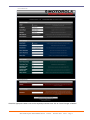
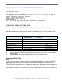
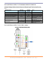
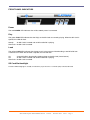
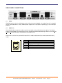
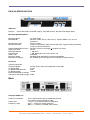
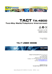
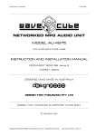
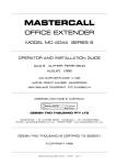
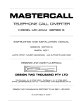
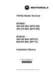
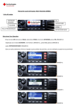
EWS 5150 Radio Emergency Warning System ACMA Supplier Code N468 ISO9001 Certified Blast Tone Generator Document G/10175 Issue 5, 06/12/2013 ISSUE 5 Design Two Thousand Pty Ltd ABN: 45 005 014 639 9-11 Rose Street Upper Ferntree Gully Melbourne Victoria 3156 Australia Telephone: +613 9758 5933 Facsimile: +613 9758 5560 Email: [email protected] Web Site: www.design2000.com.au All Rights Reserved, Copyright © 2013, Design 2000 Pty Ltd EW-5150 Description and Installation Details G/10175 December 2013 Issue 5 Page 1 PAGE LEFT BLANK EW-5150 Description and Installation Details G/10175 December 2013 Issue 5 Page 2 Document Control Document ID Document Name Security Circulation G/10175 EWS 5150 Handbook Public Domain Design 2000 Pty. Ltd., Motorola Prepared By P. Zeug Reviewed By Damien Tyrrell Approved By Roger Noble Version Control Edition Draft 1 Draft 2 Issue 1 Issue 2 Issue 3 Issue 4 Issue 5 Date 30/04/2010 03/05/2010 28/03/2011 01/04/2011 09/06/2011 29/09/2011 06/12/2013 Notes Draft only Brief description of email alerts XTL2500/5000 added General Release Activating the Blast Tone Revised XTL connections DM4601 connection added © Copyright 2013, Design 2000 Pty Ltd PRINTED IN AUSTRALIA - Contents INTRODUCTION Description and User instructions Ethernet Comms Changing the Tones Configuration over the Local Area Network EWS Alert emails PAGE 3 3 5 5 7 CONNECTIONS EW-5150 to MTM800 Accessory Connector Pinouts Activating the Blast Tone EW-5150 to XTL2500 Accessory Connector Pinouts EW-5150 to DM4601 MAP Connector Pinouts 7 7 8 8 FRONT & REAR PANEL DESCRIPTIONS Front Panel Indicators Rear Panel Connections 9 10 MP3 Volume Normalization 11 SPECIFICATIONS Part Numbers 12 14 EW-5150 Description and Installation Details G/10175 December 2013 Issue 5 Page 3 EMERGENCY WARNING SYSTEM MODEL EW-5150 Blast Tone Generator DESCRIPTION & USER INSTRUCTIONS The EW-5150 is an Emergency Warning System (EWS) for a radio network. It is also referred to as a Blast Tone Generator that plays a warning tone over the radio network prior to the commencement of blasting at mine sites. It utilizes a Motorola MTM700/MTM800 TETRA ZEON mobile radio, an XTL2500/XTL5000 ASTRO APCO P25 mobile radio or DM4601 MOTOTRBO™ mobile radio. The radio is connected to the EW-5150 via the Control Box CB-5133 with a custom made cable, part number CA-5154MTM, CA-5154XTL or CA-5154TRBO. A mining operator can place a private call to the radio (MTM) or page/alert the radio (XTL) which triggers the External Alarm function, activating the Emergency Warning System blast tone. There is also the option of using a momentary push button switch to start and stop the blast tone. By default the EWS, when triggered by a private call or page to the radio, will transmit a two-tone warning for 10 seconds. The default two-tone warning alert consists of alternating frequencies of 420 Hz & 700 Hz each of 500 ms duration. The EWS then stops transmitting for 20 seconds before transmitting the two-tone alert again. This sequence is repeated until manually cancelled by another private call or page to the radio, or automatically after the Master Timer of 10 minutes (programmable) expires. The EWS can also play a routine awareness/comfort tone that lets miners know they have radio contact. The EWS has its own internal Homepage. Using a Web browser, authorized installers and operators can change various operational parameters and these include: DHCP Email Alerts Delay/interval between Warning (Blast) Tone transmissions Total master timer for Warning (Blast) Tone cycle Awareness Tone timer (Setting 0 = off) Warning Tone volume level EW-5150 Description and Installation Details G/10175 December 2013 Issue 5 Page 4 ETHERNET COMMS On the EW-5150 back panel is an Ethernet jack which is the TCP/IP interface to the LAN/WAN and the Internet. A standard CAT5 patch cable (supplied) is used to connect the EW-5150 to an Ethernet Switch, Router or Broadband modem. PIN 1 2 3 4 5 6 7 8 DESCRIPTION TXD + TXD RXD+ Not connected Not connected RXDNot connected Not connected Pair 3 (T568A) Pair 3(T568A) Pair 2 (T568A) Pair 2 (T568A) Changing the Warning Tone and Awareness Tone files using an External Card Reader The SD Card can be ejected from the EW-5150 by applying gentle pressure, causing it to pop out of the slot. It can then be inserted into a Card reader and be seen as a mass storage device. New MP3 files can simply be ‘dragged’ across to the Card but you will need to erase existing files by re-formatting the card as a FAT or FAT16 file system before new files are ‘dragged and dropped' within Windows. You must also copy 1.mp3 first, then 2.mp3. Notes: Files must be named as follows: 1. Awareness Tone: 1.mp3 2. Alarm Tone: 2.mp3 It is highly recommended that MP3 recordings have their volume normalized to 96.0 using the MP3Gain freeware program. The MP3 files can be voice announcements rather than tones, or a combination. SD Cards are ‘hot swappable’. There is no need to remove power from the EW-5150. Playing automatically commences when another loaded SD Card is inserted and an Alarm call is received. Configuration over the Local Area Network The integrated Homepage Control Panel allows you to configure your DHCP, Username, Password and other settings. This internal configuration can only be done on your LAN. Launch your Internet Browser and enter Browser Config Address WX[serial number] eg. WX1514. You’ll find the Browser Config Address (NetBIOS name) on the base of your EW-5150. The internal Homepage control panel will appear (see next page): EW-5150 Description and Installation Details G/10175 December 2013 Issue 5 Page 5 Check the appropriate boxes and set the required parameters then click on ‘Save Changes & Reboot”. EW-5150 Description and Installation Details G/10175 December 2013 Issue 5 Page 6 EWS AUTO-MAILER EMAIL SUCCESS/FAILURE NOTIFICATION If the EWS is prevented from transmitting the blast tone, it can send and an alert email to the email address set in the configuration system: Eg. “EWS Wavecube X-Stream serial no.1514 (IP:114.77.102.19) failed to deliver message 2.mp3 (blast tone) on Thursday, November 10, 2009 at 1:15PM. Channel still busy after five attempts Input 1 (COS)is Low (active). Output 2 (PTT) is Low (inactive). Volume is set to 8. Note: This is an auto-generated email and cannot be replied to.” CONNECTION MTM, XTL & TRBO Series EW-5150 EXTERNAL CONTROL TO MTM700/MTM800 ACCESSORY CONNECTOR Connections between the External Control connector on the EW-5150 and the Accessory connector on the MTM700 or MTM800 provide the signal paths required for the EWS to operate. These are listed in the table below: Signal Description Analogue ground Audio out to radio N/C External Alarm from radio PTT to radio Rx Carrier from radio Digital Ground SWB+ EW-5150 power EW-5150 Isolated Audio & External Control 3 4 MTM800 Accessory Connector 7 2 1 2 3 4 5 4 3 5 8 13 2.1mm concentric Notes Isolated Via K1 Via Q1 Via K2 Connects to K1 & K2 Connects to K2 12Vdc 350mA plug pack (centre +ve) A special cable, part number CA-5154MTM, contains relays K1 and K2, transistor Q1 and protection diodes D1 & D2. The MTM700/800 radio must be modified to provide Rx carrier indication on pin 5. Activating the Blast Tone MTM For the blast tone to sound, the External Alarm (pin 4) of the MTM800 needs to go low (0V) for more 100ms and then go high (12V) within about 10 seconds. This sequence is then repeated to stop the blast tone. XTL For the blast tone to sound, VIP OUT 1 (pin 18) of the XTL2500 needs to go low (0V) for more than 100ms and then go high (12V) within about 10 seconds. This sequence is then repeated to stop the blast tone. Please note that a momentary push button can be used for the activation and deactivation of the blast tone – see next page. EW-5150 Description and Installation Details G/10175 December 2013 Issue 5 Page 7 EW-5150 EXTERNAL CONTROL TO XTL2500/5000 ACCESSORY CONNECTOR Connections between the External Control connector on the EW-5150 and the Accessory connector on the XTL2500 or XTL5000 provide the signal paths required for the EWS to operate. These are listed in the table below: Signal Description Analogue ground Audio out to radio N/C External Alarm from radio (VIP OUT 1) PTT to radio Rx Carrier from radio (CHAN ACT) Digital Ground SWB+ (12V) XTL2500 Accessory Connector 23 1 1 2 3 N/C (4) 18 16 N/C (13) 5 Manual Start/Stop switch EW-5150 power EW-5150 Isolated Audio & External Control 3 4 14 24 2 5 2.1mm concentric Notes Isolated Normally high, connects via K1 Connects via Q1 Optional connection, normally not connected Connects to K1 & K2 Always 12V when radio is on, connects to K2 Momentary push button N/O Momentary push button COM 12Vdc 350mA plug pack (centre +ve) EW-5150 EXTERNAL CONTROL TO MOTOTRBO™ DM4601 EW-5150 Description and Installation Details G/10175 December 2013 Issue 5 Page 8 FRONT PANEL INDICATORS Power The red POWER LED indicates that 12Vdc, 350mA power is connected. Play The green PLAY LED indicates that the file(s) on the SD Card are currently playing. When the SD Card is ejected, this LED will flash. Steady: An SD Card is inserted and an MP3 audio file is playing. Slow flash: No SD Card is inserted. Load The yellow LOAD LED indicates that the EW-5150 is in the process of downloading a new MP3 file from wavecube.com. When the SD Card is ejected, this LED will flash. On: A new MP3 file is downloading & being written to the SD Card (future feature). Off: An SD Card is inserted and an MP3 audio file is playing. Slow flash: No SD Card is inserted. SD Card Slot backlight The blue LED backlight glows steadily to indicate the proper insertion of a FAT16 (FAT) formatted SD Card. EW-5150 Description and Installation Details G/10175 December 2013 Issue 5 Page 9 REAR PANEL CONNECTIONS EW-5150 3.1 Power The EW-5150 runs from a 12Vdc power source. It draws less than 300mA . As standard, the unit is supplied with an approved 240Vac / 12Vdc, 350mA power adaptor with a concentric dc power plug, 2.1mm centre pin positive. 3.2 Audio Out The isolated audio is output on the RJ12 jack for connection to the radio external mic audio in. The default output is around 500mV p-p however this can be adjusted on the EW-5150 web page. There is an inbuilt Line Isolation Unit (LIU) so there is no need to have an external LIU. Audio Feed – use the RJ12 jack with the inbuilt LIU. It sends isolated mono (or stereo combined to mono) audio. PIN 1 2 3 4 5 6 DESCRIPTION Not connected Not connected Ring (Lb) – Sleeve, ground return Tip (La) – Signal, left & right audio mixed to mono Not connected Not connected EW-5150 Description and Installation Details G/10175 December 2013 Issue 5 Page 10 MP3 VOLUME NORMALIZATION MP3 files should be ‘normalized’ prior to uploading. This is to maintain consistent output levels. An MP3 normalization program called MP3Gain is recommended for this purpose. It is freeware however it would be appreciated if you made a donation to the authors: Download page: http://mp3gain.sourceforge.net/download.php Direct link to download current version: http://optusnet.dl.sourceforge.net/sourceforge/mp3gain/mp3gain-win-1_2_5.exe Tip! Use the setting ‘Volume 96.0’ when applying track gain to MP3 files. Use ‘Track Gain’ rather than ‘Constant Gain’. EW-5150 Description and Installation Details G/10175 December 2013 Issue 5 Page 11 EW-5150 SPECIFICATIONS Indicators Displays Power LED (Red), Load LED (Yellow), Play LED (Green), SD card slot backlight (Blue). Message Upload/Playback Message upload MP3 decoder Sample & bits rates MP3 Encode Rate Recommended MP3 bit rates Upper pass band Message retention Upload cycles Read cycles Messages length Memory Card support PC Card reader. MPEG-1 Audio Layer 3 ( ISO11172-3), supports MPEG 1 & 2 and 2.5 extensions. Mono or stereo. 8 kbits/s to 320 kbits/s CBR (Constant Bit Rate), supports VBR (Variable Bit Rate) to a peak of 320 kbits/s. 64 kbits/s mono for messages, >128 kbits/s for music. 10 kHz. > 100 years. > 100, 000 writes to any one memory cell. Unlimited. SD/MMC Card dependent, encode rate dependent. SD or MMC up to 1GB capacity, FAT16 (FAT) file system format. Processor Type PIC18F97J60 Processor Speed On Board RAM On Board Ethernet Buffer On Board FLASH External EEPROM for settings and internal web page storage 25 MHz XTAL, internally multiplied to 41.667 MHz. 3.7KB. 8KB. 128KB. 32KB. Back EW-5150 Analogue Audio Out Audio Out connectors Output level Frequency range 3.5 mm stereo phone jack for headphones/line out RJ-12 6P2C socket (isolated) for radio < 2V p-p, 1V p-p default (software adjustable) 40 Hz → 10 kHz (on stereo connector) 300 Hz → 3.4 kHz (on isolated audio socket) EW-5150 Description and Installation Details G/10175 December 2013 Issue 5 Page 12 Data Communication Ethernet 10Mbps External Control Pin 2 Pin 3 Pin 4 Pin 5 Input for Alarm from radio, active low Output for PTT to radio, active low Input for Carrier detect from radio, active low (not connected for XTL series) Ground General Operating Environment Operating Temperature Range Storage Temperature Range Humidity, Storage and Operating Mean Time Between Failure Safety EMC ACMA Supplier Code Number ERAC Responsible Supplier No. Warranty -10 +60 C -20 80 C ambient To 98% non-condensing > 20 years Complies with AS/NZS 60950 Complies with AS/NZS CISPR22 N468 E1287 Two years EW-5150 Description and Installation Details G/10175 December 2013 Issue 5 Page 13 PART NUMBERS EW-5150 CB-5133 CA-5154MTM CA-5154XTL CA-5154TRBO MTM700/MTM800 XTL2500/5000 DM4601 EWS Unit (Blast Tone Generator) Control Box Interface Cable Interface Cable Interface Cable Motorola TETRA Radio Motorola P25 Radio MOTOTRBO™ Radio Designed and Manufactured in Australia Est. 1968 Design Two Thousand Pty Ltd Melbourne Australia Telephone: 03 9758 5933 Facsimile: 03 9758 5560 Email: [email protected] Web site: www.design2000.com.au N468 EW-5150 Description and Installation Details G/10175 December 2013 Issue 5 Page 14