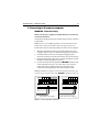
1
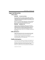
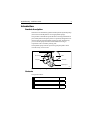
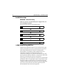
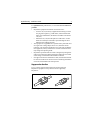
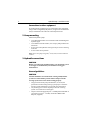
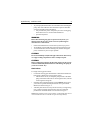
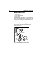
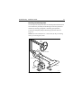
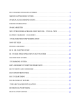
Distributed by
Any reference to Raytheon or
RTN in this manual should be
interpreted as Raymarine.
The names Raytheon and RTN
are owned by the
Raytheon Company.
Hydraulic Pump
Installation Guide
Drives covered:
M81120
Type 1 Hydraulic Pump 12 V
M81119
Type 1 Hydraulic Pump 24 V
M81121
Type 2 Hydraulic Pump 12 V
M81123
Type 2 Hydraulic Pump 24 V
M81122
Type 3 Hydraulic Pump 12 V
M81124
Type 3 Hydraulic Pump 24 V
Document number: 81178-3
March 2001
2
Hydraulic Pump - Installation Guide
Important information
Safety notices
WARNING:
Product installation
This equipment must be installed and operated in accordance
with the instructions contained in this handbook. Failure to do so
could result in poor product performance, personal injury and/
or damage to your boat.
Because correct performance of the boat’s steering is critical for
safety, we STRONGLY RECOMMEND that an Authorized
Raymarine Service Representative fits this product.
WARNING:
Navigation aid
Although we have designed this product to be accurate and
reliable, many factors can affect its performance. As a result, it
should only be used as an aid to navigation and should never
replace commonsense and navigational judgement. Always
maintain a permanent watch so you can respond to situations as
they develop.
EMC conformance
All Raymarine equipment and accessories are designed to the best
industry standards for use in the recreational marine environment.
The design and manufacture of Raymarine equipment and
accessories conform to the appropriate Electromagnetic
Compatibility (EMC) standards, but correct installation is required to
ensure that performance is not compromised.
Handbook information
To the best of our knowledge, the information in this handbook was
correct when it went to press. However, Raymarine cannot accept
liability for any inaccuracies or omissions it may contain. In addition,
our policy of continuous product improvement may change
specifications without notice. As a result, Raymarine cannot accept
liability for any differences between the product and the handbook.
© Raymarine Ltd 2001.
Hydraulic Pump - Installation Guide
3
Introduction
Product description
Welcome to the installation guide for the Raymarine hydraulic pump
(also known as the Raymarine reversing hydraulic pump).
This product is intended to operate the boat’s steering mechanism as
part of a Raymarine autopilot system. It is primarily designed for use
on boats with an existing hydraulic steering system. Alternatively,
you can use this pump on a boat with mechanical steering in
conjunction with a secondary steering ram.
The hydraulic pump contains a precision gear pump and a check
valve driven by a servo motor.
Ram ports
Reservoir port
Motor
Gear pump
Check valve
Mounting foot
D5175-1
Figure 1: Main parts of a typical hydraulic pump
Contents
This guide contains:
1
Product specifications
page 4
2
Installation instructions
page 5
3
Maintenance information
page 17
4
Hydraulic Pump - Installation Guide
Specifications
Pump specifications
Table 1: Pump specifications
Type 1 (T1)
M81120 (12 V)
M81119 (24 V)
Performance
(at nominal voltage)
Ram compatibility
Type 2 (T2)
M81121 (12 V)
M81123 (24 V)
Type 3 (T3)
M81122 (12 V)
M81124 (24 V)
single or double ended
Ram capacity
(min-max)
80-230 cc
(4.9-14 in3)
230-350 cc
(14-21 in3)
350-500 cc
(21-30.5 in3)
Maximum stall
pressure (at 12 V)
50 bar
(750 psi)
100 bar
(1450 psi)
80 bar
(1160 psi)
Peak flow rate
(no load)
1000 cc/min
(67 in3/min)
2000 cc/min
(122 in3/min)
2900 cc/min
(175 in3/min)
Other information
(applies to Types 1, 2 and 3)
protected for use in engine compartments
CE approvals - conforms to:
89/336/EC (EMC), EN60945:1997
94/25/EC (RCD), EN28846:1993
Pump dimensions
90 mm (3.54 in)
All ports are 1/4 inch BSP (parallel threaded)
two holes to accept 6 mm (0.25 in) bolts
175 mm (6.9 in)
105 mm (4.13 in)
Type 1 (12 V) and Type 2 pumps
Figure 2: Type 1 (12 V) and Type 2 pump dimensions
D5174-1
Hydraulic Pump - Installation Guide
5
103 mm (4.07 in)
All ports are 1/4 inch BSP (parallel threaded)
holes to accept 6 mm (0.25 in) bolts
235 mm (9.25 in)
Type 3 pump
117 mm (4.62 in)
D5173-1
Figure 3: Type 3 pump dimensions
Installation instructions
Parts required
To install this drive you will need:
•
•
Parts supplied:
• hydraulic pump
• if required: 1/4 in BSP to 1/4 in NPT adaptors (x3)
Additional parts:
• suitable hydraulic pipes, hydraulic fluid, T-pieces, pipe
fittings and thread-sealing compound (see page 8)
• suitable securing bolts and lock washers/lock nuts (see
page 8)
• suitable cable and electrical connectors for the drive motor
and clutch (see page 13)
Note: Make sure you have obtained these additional parts before you
start installation.
6
Hydraulic Pump - Installation Guide
Installation steps
WARNING: Electrical safety
Make sure you have switched off the power supply before you
start installing this product.
Follow these steps to install your hydraulic pump:
1
Consult the EMC installation guidelines.
page 6
Ï
2
Mount the pump.
page 8
Ï
3
Connect to the hydraulic steering system.
page 8
Ï
4
Connect to the course computer.
page 13
Ï
5
Complete the post-installation checks.
page 15
1. EMC installation guidelines
All Raymarine equipment and accessories are designed to the best
industry standards for use in the recreational marine environment.
Their design and manufacture conforms to the appropriate
Electromagnetic Compatibility (EMC) standards, but correct
installation is required to ensure that performance is not
compromised. Although every effort has been taken to ensure that
they will perform under all conditions, it is important to understand
what factors could affect the operation of the product.
The guidelines given here describe the conditions for optimum EMC
performance, but it is recognized that it may not be possible to meet
all of these conditions in all situations. To ensure the best possible
conditions for EMC performance within the constraints imposed by
any location, always ensure the maximum separation possible
between different items of electrical equipment.
Hydraulic Pump - Installation Guide
7
For optimum EMC performance, it is recommended that wherever
possible:
•
•
•
•
Raymarine equipment and cables connected to it are:
• At least 3 ft (1 m) from any equipment transmitting or cables
carrying radio signals e.g. VHF radios, cables and antennas.
In the case of SSB radios, the distance should be increased to
7 ft (2 m).
• More than 7 ft (2 m) from the path of a radar beam. A radar
beam can normally be assumed to spread 20 degrees above
and below the radiating element.
The equipment is supplied from a separate battery from that used
for engine start. Voltage drops below 10 V, and starter motor
transients, can cause the equipment to reset. This will not damage
the equipment, but may cause the loss of some information and
may change the operating mode.
Raymarine specified cables are used. Cutting and rejoining these
cables can compromise EMC performance and must be avoided
unless doing so is detailed in the installation manual.
If a suppression ferrite is attached to a cable, this ferrite should not
be removed. If the ferrite needs to be removed during installation
it must be reassembled in the same position.
Suppression ferrites
Figure 4 shows typical cable suppression ferrites used with
Raymarine equipment. Always use the ferrites supplied by
Raymarine.
D3548-2
Figure 4: Typical Suppression Ferrites
8
Hydraulic Pump - Installation Guide
Connections to other equipment
If your Raymarine equipment is to be connected to other equipment
using a cable not supplied by Raymarine, a suppression ferrite MUST
always be attached to the cable near to the Raymarine unit.
2. Pump mounting
Mount the hydraulic pump:
•
•
•
•
on a substantial member to avoid vibration that could damage the
hydraulic pipes
on a suitable horizontal surface, clear of spray and possible water
immersion
level or above the hydraulic steering ram to prevent air collecting
in the ram
as close to the ram as possible
Note: Secure the pump using M6 (1/4 inch) bolts, lock nuts and lock
washers.
3. Hydraulic connections
CAUTION:
Before you connect the autopilot pump to your hydraulic system
we strongly recommend that you consult the steering gear
manufacturer.
General guidelines
CAUTION:
Absolute cleanliness is essential when working with hydraulic
systems. Even the smallest particle of dirt could prevent the
steering system check valves from working properly.
•
•
•
All pipes used to fit the pump should match, or exceed, the
specification of the existing steering system pipes. Contact the
steering system manufacturer if you need more information.
Use flexible pipe to connect the pump to the boat’s steering
system - this avoids strain on the pipes.
All ports on the autopilot pump are 1/4 in BSP parallel threaded. If
you need to convert to 1/4 in NPT, use the three BSP to NPT
adaptors (supplied).
Hydraulic Pump - Installation Guide
•
9
Try to keep hydraulic fluid loss to a minimum when installing the
pump. This will reduce the time and effort required to bleed the
system of trapped air after installation:
• non-pressurized systems: temporarily fit a non-venting plug
to the helm reservoir vent to minimize fluid loss
• pressurized systems:
WARNING:
Before disconnecting any pipes on pressurized systems, you
MUST release the pressure at the reservoir by following the
manufacturer’s instructions.
•
•
•
Follow the manufacturer’s instructions if you fit any T-pieces.
All hydraulic pipes should slope upwards towards the reservoir.
A set of bleed valves near the steering ram, fitted at the highest
point, will allow any air to escape upwards.
CAUTION:
Do not use PTFE tape on hydraulic pipe connections. If necessary
use a pipe-sealing compound to ensure a leakproof joint.
CAUTION:
Before running the pump for the first time, make sure the system
contains sufficient hydraulic fluid. You will damage the pump if
you let it run when ‘dry’.
Check valves
For single-steering position boats:
•
•
•
Consult the steering gear manufacturer to determine whether the
helm pump is fitted with reversing check valves:
• without check valves, the autopilot pump will drive the helm
pump (sometimes referred to as ‘motoring the wheel’) instead
of moving the steering ram
If the boat has a single helm pump system without check valves,
you must incorporate a double pilot check valve (part number
M81166) as shown in Figure 5.
A double pilot check valve may also be necessary on long tubing
runs - otherwise tubing expansion may cause poor autopilot
performance. Install the check valve as shown in Figure 5.
Note: If the boat has two steering positions, it will already have check
valves installed so the two wheels can operate independently.
10
Hydraulic Pump - Installation Guide
Hydraulic steering systems
There are three basic types of hydraulic steering systems:
•
•
•
two line systems
two line pressurized systems
three line systems
On the following pages we describe typical connection points for the
autopilot pump on each of these systems. For all of the systems you
will need to connect a third hydraulic pipe (as shown) between the
autopilot pump and the helm pump or system reservoir.
Two line systems
Figure 5 shows a typical two line steering system. Hydraulic fluid
flows into the ram in either direction, depending on the direction the
helm pump rotates. Connect the autopilot pump to the steering
system as shown in Figure 5.
Helm
pump
Check valve (if required)
Reservoir pipe
Ram pipes
Autopilot
pump
Steering ram
D5163-1
Figure 5: Autopilot pump location for two line systems
Hydraulic Pump - Installation Guide
11
Two line pressurized systems
Two line pressurized systems have an external pressurized reservoir.
This reduces the possibility of introducing air into the system and
reduces any steering ‘sponginess’ caused by pipe expansion.
Connect the autopilot pump to the steering system as shown in
Figure 6.
Note: Refer to the manufacturer’s instructions for de-pressurizing
and re-pressurizing the system.
Helm
pump
Pressurized reservoir
Reservoir pipe
Ram pipes
Steering ram
Autopilot
pump
D5162-1
Figure 6: Autopilot pump location for two line pressurized systems
12
Hydraulic Pump - Installation Guide
Three line systems
In a three line system, the hydraulic fluid flows in only one direction:
•
•
out of the helm pump to the ram
returning from the other side of the ram to the reservoir via a
common return line
The system will include a check valve block to direct all returned
fluid from the ram back to the reservoir.
Connect the autopilot pump to the steering system as shown in
Figure 7.
Helm
pump
Check valve
Reservoir
pipe
Ram pipes
Steering ram
Autopilot
pump
D5161-1
Figure 7: Autopilot pump location for three line systems
Hydraulic Pump - Installation Guide
13
4. Connecting to the course computer
WARNING: Electrical safety
Make sure the power supply is switched off before you make any
electrical connections.
The hydraulic pump has electrical connections for its motor: a red and
a black cable.
Note: To meet current EMC legislation, you must NOT untwist the
pump cables, and you must NOT remove the suppression ferrite.
Follow these steps to connect the pump motor to the course computer:
1. Measure the distance of cable run from the pump to the course
computer, then use Table 2 to identify the appropriate cable sizes.
2. Join these cables to the ones on the pump using appropriate
electrical connectors or junction boxes at the correct power rating.
3. Route the cables back to the course computer, taking into account
the EMC installation guidelines (page 6).
4. Connect the cables from the pump to the MOTOR terminals on the
course computer (see Figure 8): at this stage you can connect
either motor cable to either terminal. You will check these
connections after installing the rest of the autopilot system.
Note: If installing the pump on a boat with mechanical steering, you
need to connect a bypass valve to the CLUTCH terminals (see page 14).
OFF
SWITCH
– +
A B
POWER MOTOR
– –
– +
SOLENOID CLUTCH
Type 150/400 course computer
– +
lk CLUTCH
– +
1
2
POWER MOTOR
Type 100/300 course computer
D5171-1
Figure 8: Course computer connections
14
Hydraulic Pump - Installation Guide
Table 2: Recommended cable sizes
Cable length
(pump to course computer)
Cable gauge
(AWG)
Copper area
(mm2)
Type 1 drive (12 V and 24 V)
up to 3 m (10 ft)
up to 5 m (16 ft)
up to 7 m (23 ft)
up to 10 m (32 ft)
up to 16 m (52 ft)
14
12
10
8
6
2.5
4
6
10
16
Type 2 drive 12 V
up to 5 m (16 ft)
up to 7 m (23 ft)
up to 16 m (52 ft)
10
8
6
6
10
16
Type 2 drive 24 V
up to 3 m (10 ft)
up to 5 m (16 ft)
up to 10 m (32 ft)
up to 16 m (52 ft)
12
10
8
6
4
6
10
16
Type 3 drive 12 V
up to 5 m (16 ft)
up to 7 m (23 ft)
up to 16 m (52 ft)
8
6
4
10
16
25
Type 3 drive 24 V
up to 5 m (16 ft)
up to 7 m (23 ft)
up to 16 m (52 ft)
10
8
6
6
10
16
Mechanical steering systems
If you are fitting the pump to a boat with mechanical steering you will
need to connect it to a secondary steering ram, along with a solenoidoperated bypass valve. This bypass valve allows you to switch
between autopilot course control and manual steering.
To fit to a mechanical steering system:
•
•
•
Use suitable hydraulic pipes to connect the pump to the secondary
steering ram and a suitable reservoir.
Install the solenoid-operated bypass valve (part number:
M81167) across these pipes (as shown in Figure 9).
Connect the bypass valve to the CLUTCH terminals on the course
computer using at least 1.5 mm2 (16 AWG) copper cable.
Hydraulic Pump - Installation Guide
15
Note: Follow the manufacturer’s instructions for mounting the
hydraulic ram and reservoir.
Secondary steering ram
Bypass valve
Manual steering system
Autopilot pump
connect to CLUTCH
on course computer
connect to MOTOR
on course computer
D5172-2
Figure 9: Connecting to a secondary steering ram
5. Post-installation check
WARNING:
Keep clear of moving steering systems at all times. Protect
moving parts from access during normal use.
Check the following points after installing the pump:
1. Is the pump installed as close to the steering ram as possible?
2. Is the pump secured to a substantial structure on the boat?
3. Have you connected a reservoir pipe between the helm pump and
autopilot pump?
4. Have you fitted check valves where appropriate?
5. Are the hydraulic pipes made of a suitable flexible material (i.e.
rubber or nylon) with a suitable pressure rating?
6. Are power cables correctly routed and securely connected to the
course computer?
You have now finished installing the pump. After installing the rest of
the autopilot you must bleed all air from the system (see below).
Note: When you have installed the entire autopilot system, you will
also need to complete an autopilot steering check. Refer to the control
unit handbook for more details.
16
Hydraulic Pump - Installation Guide
Bleeding the system
Bleeding the hydraulic system correctly is one of the most important
steps when installing the autopilot hydraulic pump. If there is any air
in the system the steering will feel spongy, particularly when you turn
the wheel to hardover.
CAUTION:
Any air in the hydraulic system will greatly reduce the
performance of the autopilot and the overall steering system.
In addition to the manufacturer’s instructions for bleeding the
steering system, follow these steps to bleed the autopilot pump when
you have installed and set up the rest of the autopilot system:
1. With the system in auto mode, press the -10 button ten times:
• the autopilot pump will try to drive the rudder to port
• counter this rudder movement by turning the helm to
starboard to keep the rudder stationary
• you will be able to feel any air in the helm pump: any air in this
side of the pump will rise to the helm pump and exhaust into
the reservoir
• continue until all of the air is out of this side of the pump
2. Clear any air on the other side of the pump:
• press the +10 button ten times
• the autopilot will try to drive the rudder to starboard
• counter the rudder movement by turning the helm to port
• continue until all of the air is out of this side of the pump
3. Repeat in both directions until both sides of the help pump are
totally free of air.
Note: Monitor the reservoir at all times and top up with the
manufacturer’s recommended hydraulic fluid as required.
CAUTION:
After installation and bleeding, leave the system for 24 hours
then check for any air in the system or leaks at the joints and
around the pump.
Hydraulic Pump - Installation Guide
17
Maintenance
On a regular basis:
•
•
•
check that all connections and mountings are secure
check pipes and cables for any signs of wear or damage
check pipes and joints for any leaks
EMC servicing and safety guidelines
•
•
•
•
•
Raymarine equipment should be serviced only by authorized
Raymarine service technicians. They will ensure that service
procedures and replacement parts used will not affect
performance. There are no user serviceable parts in any
Raymarine product.
Some products generate high voltages: never handle the cables/
connectors when power is being supplied to the equipment.
When powered up, all electrical equipment produces
electromagnetic fields. These can cause adjacent pieces of
electrical equipment to interact with one another, with a
consequent adverse effect on operation. In order to minimize
these effects and enable you to get the best possible performance
from your Raymarine equipment, guidelines are given in the
installation instructions, to enable you to ensure minimum
interaction between different items of equipment, i.e. ensure
optimum Electromagnetic Compatibility (EMC).
Always report EMC-related problems to your nearest Raymarine
dealer. We use such information to improve our quality standards.
In some installations, it may not be possible to prevent the
equipment from being affected by external influences. In general
this will not damage the equipment but it can lead to spurious
resetting action, or momentarily may result in faulty operation.
Product support
Raymarine products are supported by a worldwide network of
distributors and Authorized Service Representatives. If you
encounter any difficulties with this product, please contact either
your national distributor, or your service representative, or the
Raymarine Technical Services Call Center. Refer to the back cover
or the Worldwide Distributor List for contact details.
18
Raymarine Ltd
Anchorage Park
Portsmouth, Hampshire
England PO3 5TD
Telephone +44 (0)23 9269 3611
Fax +44 (0)23 9269 4642
www.raymarine.com
Hydraulic Pump - Installation Guide
Raymarine Inc
22 Cotton Road, Suite 280
Nashua
NH 03063-4219, USA
Telephone +1 603 881 5200
Fax +1 603 864 4756
www.raymarine.com
Raymarine Technical Services Call Center
UK: +44 (0)23 9271 4713 or
USA: +1 603 881 5200 or
+44 (0)23 9269 3611 ext. 1083
1-800-539-5539 ext. 2333