1
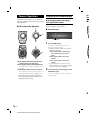
FOR CAR USE ONLY
2
TOPVIEW® CAMERA SYSTEM
HCE-C500
• OWNER’S MANUAL
Please read before using this equipment.
ALPINE ELECTRONICS MARKETING, INC.
1-1-8 Nishi Gotanda,
Shinagawa-ku,
Tokyo 141-0031, Japan
Phone 03-5496-8231
ALPINE ELECTRONICS OF AUSTRALIA PTY. LTD.
ALPINE ELECTRONICS OF AMERICA, INC.
19145 Gramercy Place, Torrance,
California 90501, U.S.A.
Phone 1-800-ALPINE-1 (1-800-257-4631)
ALPINE ELECTRONICS OF CANADA, INC.
777 Supertest Road, Toronto,
Ontario M3J 2M9, Canada
Phone 1-800-ALPINE-1 (1-800-257-4631)
161-165 Princes Highway, Hallam
Victoria 3803, Australia
Phone 03-8787-1200
ALPINE ITALIA S.p.A.
Viale C. Colombo 8, 20090 Trezzano
Sul Naviglio (MI), Italy
Phone 02-484781
ALPINE ELECTRONICS GmbH
Wilhelm-Wagenfeld-Str. 1-3,
80807 München, Germany
Phone 089-32 42 640
ALPINE ELECTRONICS DE ESPAÑA, S.A.
Portal de Gamarra 36, Pabellón, 32
01013 Vitoria (Alava)-APDO 133, Spain
Phone 945-283588
ALPINE ELECTRONICS OF U.K. LTD.
Alpine House
Fletchamstead Highway,
Coventry CV4 9TW, U.K.
Phone 0870-33 33 763
ALPINE ELECTRONICS (BENELUX) GmbH
Leuvensesteenweg 510-B6,
1930 Zaventem, Belgium
Phone 02-725-13 15
ALPINE ELECTRONICS FRANCE S.A.R.L.
(RCS PONTOISE B 338 101 280)
98, Rue de la Belle Etoile, Z.I. Paris Nord Il,
B.P. 50016, 95945 Roissy Charles de Gaulle
Cedex, France
Phone 01-48638989
YAMAGATA Co., Ltd.
2-6-34, Takashima, Nishi-ku, Yokohama-shi,
Kanagawa, 220-8515 Japan
Designed by ALPINE Japan
Printed in Japan (Y_A5)
68-18693Z84-A
ALPINE HCE-C500 EN 68-18693Z84-A (A5)
EN
ALPINE HCE-C500 EN 68-18693Z84-A (A5)
ENGLISH
Contents
Operating Instructions
WARNING
WARNING ........................................ 2
CAUTION ......................................... 3
NOTICE ............................................. 3
Installation and Connections
Check Accessory Parts....................17
Connections .....................................18
System Example ..............................19
Information
Specifications ...................................20
In Case of Difficulty .......................20
Feature
About the TOPVIEW® CAMERA
SYSTEM ..........................................4
Example of Camera Installation.............. 4
Example of Camera Image ....................... 4
Camera Image
Image Patterns and Distance
Guidelines .......................................6
How to Interpret a Camera Image .......... 6
About the Front Camera Image and
Camera Guide ........................................ 7
About the Rear Camera Image and
Camera Guide ........................................ 8
Error Between the Display and Actual
Road Surface ......................................... 10
About Calibration ...........................12
About the Image Range ..................12
Camera Operation
Displaying the Camera Image .......14
Displaying the Camera Image by
Pressing the PDC button .................... 14
Displaying the Camera Image using the
iDrive Controller.................................. 15
Displaying the rear view image while the
car is in reverse ..................................... 15
Switching Image Patterns ...............16
1-EN
ALPINE HCE-C500 EN 68-18693Z84-A (A5)
Operating Instructions
WARNING
WARNING
This symbol means important instructions.
Failure to heed them can result in serious
injury or death.
WHEN USING A CAMERA SYSTEM, THE DRIVER MUST
VISUALLY CHECK ACTUAL CONDITIONS AROUND
THE VEHICLE. MAKE SURE THERE ARE NO PERSONS
OR ANIMALS IN THE AREA IN WHICH YOU ARE
MANEUVERING OTHERWISE YOU COULD INJURE THEM.
A camera assists the driver by sending images to the screen
showing conditions in view of the camera. The camera uses
a wide-angle lens. Therefore, there is a difference in distance
perspective between what is normally seen and what appears
on the screen. Also, the images shown by the rear camera are
reversed, so as to appear the same as what is seen through the
rearview mirror.
The camera may not perform to full capability due to
variables such as:
• weather conditions such as hard rain, snow, fog or mud
• extremely high or low temperatures near camera
• slope of vehicle and/or roadway
• direct exposure to very bright light such as headlamp or
bright sunlight
• moving from very dark to very bright light and vice versa
such as in parking garages or tunnels
• extremely low light areas
• walls or objects that are located diagonally in relation to
the camera
• retracted mirrors that change camera viewing angle
• open doors or trunks
• changes to height of vehicle due to loading capacity or
hydraulic suspensions
• obstacles located at the corner of the vehicle
DO NOT DISASSEMBLE OR ALTER.
Doing so may result in an accident, fire or electric shock.
KEEP SMALL OBJECTS SUCH AS BOLTS OR SCREWS OUT
OF THE REACH OF CHILDREN.
Swallowing them may result in serious injury. If swallowed,
consult a physician immediately.
USE THE CORRECT AMPERE RATING WHEN REPLACING
FUSES.
Failure to do so may result in fire or electric shock.
DO NOT USE BOLTS OR NUTS IN THE BRAKE OR
STEERING SYSTEMS TO MAKE GROUND CONNECTIONS.
Bolts or nuts used for the brake or steering systems (or any
other safety-related system), or tanks should NEVER be used
for installations or ground connections. Using such parts
could disable control of the vehicle and cause fire etc.
DO NOT DAMAGE PIPE OR WIRING WHEN DRILLING
HOLES.
When drilling holes in the chassis for installation, take
precautions so as not to contact, damage or obstruct pipes,
fuel lines, tanks or electrical wiring. Failure to take such
precautions may result in fire.
MINIMIZE DISPLAY VIEWING WHILE DRIVING.
Viewing the display may distract the driver from looking
ahead of the vehicle and cause an accident.
DO NOT SPLICE INTO ELECTRICAL CABLES.
Never cut away cable insulation to supply power to other
equipment. Doing so will exceed the current carrying
capacity of the wire and result in fire or electric shock.
HAVE
EXPE
The w
techn
conta
the w
ARRA
PINC
Route
the se
crimp
USE S
SECU
Be su
than d
not se
becom
DO NOT ALLOW CABLES TO BECOME ENTANGLED IN
SURROUNDING OBJECTS.
Arrange wiring and cables in compliance with the manual
to prevent obstructions when driving. Cables or wiring that
obstruct or hang up on places such as the steering wheel, gear
lever, brake pedals, etc. can be extremely hazardous.
CONN
Be su
the di
to ma
system
DO NOT ROUTE ELECTRICAL CABLES NEAR HOT OR
MOVING PARTS
Route the cables and wiring away from hot or moving parts,
and fix them securely to avoid heat/mechanical damage to
the cable insulation, which may result in shortcircuit, fire or
electric shock.
MAKE THE CORRECT CONNECTIONS.
When making connections to the vehicle’s electrical system,
be aware of the factory installed components (e.g. on-board
computer). Do not tap into these leads to provide power
for this unit. When connecting the device to the fuse box,
make sure the fuse for the intended circuit of the device has
the appropriate amperage. Failure to do so may result in fire
or damage to the unit and/or the vehicle. When in doubt,
consult your Alpine dealer.
USE ONLY IN CARS WITH A 12 VOLT NEGATIVE GROUND.
(Check with your dealer if you are not sure.) Failure to do so
may result in fire, etc.
BEFORE WIRING, DISCONNECT THE CABLE FROM THE
NEGATIVE BATTERY TERMINAL.
Failure to do so may result in electric shock or injury due to
electrical shorts.
CHECK THAT THE CAMERA MOUNTINGS IS ATTACHED
SECURELY, AND THAT THE SCREWS ARE TIGHT BEFORE
DRIVING.
Failure to do so may result in an accident.
WHEN INSTALLING OR CHECKING A CAMERA, DO SO
AFTER PARKING THE CAR IN A LEVEL, SAFE PLACE,
TURNING OFF THE ENGINE, AND APPLYING THE HAND
BRAKE.
Failure to do so may result in an accident.
ALPINE HCE-C500 EN 68-18693Z84-A (A5)
Th
Fai
ma
DO NOT INSTALL IN LOCATIONS WHICH MIGHT HINDER
VEHICLE OPERATION, SUCH AS THE STEERING WHEEL
OR GEAR LEVER.
Doing so may obstruct forward vision or hamper movement
etc. and results in serious accident.
USE THIS PRODUCT FOR MOBILE 12 VOLT
APPLICATIONS.
Use for other than its designed application may result in fire,
electric shock or other injury.
2-EN
WHEN
PREC
FRAG
Failur
HALT
Failur
produ
neare
EXCE
TO AR
LOT O
Failur
DO N
RESIN
Doing
could
dama
DO N
THE E
Doing
could
dama
WHEN USING A DRILL TO MAKE A HOLE, TAKE
PRECAUTIONS SUCH AS WEARING GOGGLES SO
FRAGMENTS DO NOT GET INTO THE EYES.
Failure to do so may result in injury.
ONS.
ny
used
s
es,
g
r
DER
EL
ment
N
al
hat
, gear
arts,
to
e or
em,
ard
x,
has
fire
t,
fire,
CAUTION
This symbol means important instructions.
Failure to heed them can result in injury or
material property damage.
HAVE THE WIRING AND INSTALLATION DONE BY
EXPERTS.
The wiring and installation of this unit requires special
technical skill and experience. To ensure safety, always
contact the dealer where you purchased this product to have
the work done.
ARRANGE THE WIRING SO IT IS NOT CRIMPED OR
PINCHED BY A SHARP METAL EDGE.
Route the cables and wiring away from moving parts (like
the seat rails) or sharp or pointed edges. This will prevent
crimping and damage to the wiring.
USE SPECIFIED ACCESSORY PARTS AND INSTALL THEM
SECURELY.
Be sure to use only the specified accessory parts. Use of other
than designated parts may damage this unit internally or may
not securely install the unit in place. This may cause parts to
become loose resulting in hazards or product failure.
CONNECT LEADS PROPERLY.
Be sure to connect the colour coded leads according to
the diagram. Incorrect connections may cause the unit
to malfunction or cause damage to the vehicle’s electrical
system.
NOTICE
• About Care of Device
Do not assert any excess pressure to the camera or the
mounting, as this could cause the camera direction to shift,
or the camera mounting bracket to come off.
• To prevent the camera lens, mounting and cords from
changing colour or shape, or from deteriorating, wipe with
a chemical-free, damp cloth.
• Do not use an automatic car wash or high-pressure washer.
Doing so could cause the camera to come off, damage to
the device cord, or may allow water to enter the camera or
the inside of the car.
• In some cases, to attach the device, a hole must be drilled
in the car body, requiring use of touch-up paint (retail
product) for rust-prevention, and should be prepared
beforehand.
• Be sure to disconnect the cable from the (–) battery post
before installing your HCE-C500 series. This will reduce
any chance of damage to the unit in case of a short-circuit.
• About Rear Camera
The rear camera is optimised for use in this system. as a
dedicated product, it should not be used in other systems.
• Do not use mobile phones and wireless devices near the
camera.
Doing so may result in noise on the screen or malfunction.
It is recommended to use mobile phones or wireless devices
away from the camera.
• About Camera Installation Location
Before installing, make sure there is a enough space to be
able to install the camera. If possible, install the camera
in the center of the bumper. If the camera is installed
off-center, the image may differ from the actual view.
Calibration is necessary.
• Confirming the Display Function
To connect the unit, confirm that the monitor will require a
compatible RCA pin jack.
HALT USE IMMEDIATELY IF A PROBLEM APPEARS.
Failure to do so may cause personal injury or damage to the
product. Return it to your authorized Alpine dealer or the
nearest Alpine Service Center for repairing.
EXCEPT FOR THE CAMERA, DO NOT ATTACH ANY PARTS
TO AREAS WHICH WILL GET WET, OR WHERE THERE IS A
LOT OF HUMIDITY OR DUST.
Failure to do so may result in fire or damage.
DO NOT ATTACH THE CAMERA TO FLUOROCARBON
RESIN FINISHED CAR BODIES OR GLASS.
Doing so reduces the strength of the camera’s mounting.This
could cause it to fall off and cause injury or
damage to the car’s body.
DO NOT ATTACH THE CAMERA TO ANY SURFACE WHERE
THE ENTIRE ADHESIVE SURFACE CANNOT BE APPLIED.
Doing so reduces the strength of the camera’s mounting.This
could cause it to fall off and cause injury or
damage to the car’s body.
ED
ORE
O
ND
3-EN
ALPINE HCE-C500 EN 68-18693Z84-A (A5)
eR
Feature
<Re
About the TOPVIEW® CAMERA SYSTEM
The TOPVIEW® CAMERA SYSTEM displays the blind area outside the driver’s range of vision, using
four cameras installed on the front, back, right and left of the vehicle. It is useful for checking for objects
around the vehicle. For example, when parking, when navigating narrow roads and “blind” corners, and
when reversing.
Example of Camera Installation
Side camera
<Re
Front camera
Side camera
Rear camera
• An installation kit suitable for your vehicle model is required to install this system.
Performance cannot be assured if you install this system by any other means.
Example of Camera Image
e Front View Display Indications
<Front Panorama View>
<Front Side View>
• Wi
the
• Dep
Ca
<Front Top View>
4-EN
ALPINE HCE-C500 EN 68-18693Z84-A (A5)
<Front Corner View>
e Rear View Display Indications
<Rear Panorama View>
<Rear Mirror View>
<Rear Top View>
<Rear View>
g
ects
and
• With this system, the brightness and tint of each camera is automatically adjusted. When driving in areas where
the brightness or tint varies widely, the brightness or tint of the camera image on the screen may become unstable.
• Depending on the condition of the car or road surface, the range of vision may vary. Refer to “About the Front
Camera Image and Camera Guide” (page 7) or “About the Rear Camera Image and Camera Guide” (page 8).
5-EN
ALPINE HCE-C500 EN 68-18693Z84-A (A5)
Abo
Cam
Camera Image
Image Patterns and Distance Guidelines
eF
This camera system synthesises and combines four camera images, enabling you to select and switch to
any image pattern. The distance guidelines displayed vary for each pattern. For details of how to switch
image patterns, refer to “Camera Operation” (page 14).
How to Interpret a Camera Image
<Front Panorama View>
<Rear View>
Caution message *1
A
Disp
front
Use t
chec
emer
wher
Caution message *1
B
Camera Image Range
* Varies with image pattern
Vehicle width extension
marks
* Only displayed in the
rear view image.
Distance guidelines
* Vary with image pattern
*D
eF
*1 If no caution message is displayed, be sure to make the correct display settings. Have an authorized Alpine
dealer perform the correct display settings in calibration mode.
A: Current image range
B: Current image pattern
The
side
Use t
on ea
hard
<Front View Image>
p Front Panorama
View
p Front Side View
p Front Top View
p Front Corner View
A
A
A
A
B 1 FP
B 2 FS
B 3 FT
B 4 FC
p Rear Mirror View
p Rear Top View
p Rear View
A
A
A No icon
B 2 RM
B 3 RT
B 4R
<Rear View Image>
p Rear Panorama
View
A No icon
B 1 RP
6-EN
ALPINE HCE-C500 EN 68-18693Z84-A (A5)
Le
p I
AG
a
BG
a
About the Front Camera Image and
Camera Guide
e Front Panorama View
to
ch
Displays a wider-angled perspective of the area in
front of the vehicle.
Use this when you want to make a wide-sweeping
check in front of the vehicle. For example, when
emerging from a narrow street onto a main road
where the oncoming traffic is hard to see.
e Front Top View
The split-screen image displays an all-round view
from above the vehicle and the front view.
Use this when you want to check for objects
around or in front of the vehicle. For example,
when parking the vehicle in a garage.
Top View
Front View
1
C
s
ttern
p Indication mark meaning
* Distance guidelines are not displayed.
e Front Side View
ne
B
A
The split-screen image displays the area on each
side in front of the vehicle.
Use this when you want to check the area ahead
on each side. For example, when pulling onto a
hard shoulder or pulling over to a kerb.
B
ew
A Guidelines representing a distance of
approx. 0.5 m on each side of the vehicle.
B Guidelines representing a distance of
approx. 0.5 m in front of the vehicle.
C Guidelines representing a distance of
approx. 0.5 m all round the vehicle.
• Top View synthesises images from 4 cameras
and displays the combined view on the monitor.
As the sensitivity of each camera is individually
adjusted to the optimal degree, the image on
the monitor may appear rather unnatural
(brightness, tint, etc.).
e Front Corner View
Displays a divided image left and right of centre.
Use this mainly when checking the left and right
directional view.
Left Side View
A
Right Side View
p Indication mark meaning
A Guidelines representing a distance of
approx. 0.5 m on each side of the vehicle.
B Guidelines representing a distance of
approx. 0.5 m in front of the vehicle.
Left Side Corner View
Right Side Corner View
* Distance guidelines are not displayed.
7-EN
ALPINE HCE-C500 EN 68-18693Z84-A (A5)
• With Top View, the camera image around the joins
•
•
•
•
e Rear Mirror View
p In
or borders may not be displayed. For details, refer to
The triple-screen image displays the area on each
“About Top View Blind Spots” (page 13).
side behind the vehicle.
Do not use Top View while retracting the door
Use this when you want to check the area on
mirrors or when the vehicle doors are not completely
each side behind the vehicle. For example, when
closed, as the image will not be displayed properly.
For details of how to switch image patterns, refer to
reversing into a garage, reversing onto a hard
“Camera Operation” (page 14).
shoulder or pulling over to a kerb in reverse.
In the following conditions, screen visibility may be
Left Mirror View
Right Mirror View
impaired. This is not a malfunction.
D
D
– When it is dark (at night, etc.).
– When the temperature around the camera lens is
high or low.
– When water drops adhere to the camera, or when
the humidity is high (such as rainy weather, etc.).
A
– When foreign bodies (such as mud, etc.) adhere to A
the camera or its peripheral area.
– When sunlight or headlights directly strike the
camera lens.
The image range will be affected by the height or
inclination of the vehicle. The position indicated
by the distance guidelines, actual distance from
the road surface and distances from objects will
vary, depending on factors such as number of
Rear View
passengers, load weight and suspension adjustments.
In addition, joins in Top View images may not be
properly aligned. Always visually check the actual
p Indication mark meaning
conditions around the vehicle to ensure safety.
About the Rear Camera Image and
Camera Guide
A Guidelines representing a distance of
approx. 0.5 m on each side of the vehicle.
D Guidelines representing a distance of
approx. 0.5 m behind the vehicle.
e Rear Panorama View
• Rear View: Refer to “Rear View” (page 9).
Displays a wider-angled perspective of the area
behind the vehicle.
Use this when you want to make a wide-sweeping
check behind the vehicle. For example, when you
are reversing out of a narrow street onto a main
road where the oncoming traffic is hard to see.
e Rear Top View
* Distance guidelines are not displayed.
C
8-EN
ALPINE HCE-C500 EN 68-18693Z84-A (A5)
• Re
• Top
and
As
adj
the
(br
• Wi
•
•
•
•
•
The split-screen image displays an all-round view
from above the vehicle and the rear view.
Use this when you want to check for objects
around or behind the vehicle. For example, when
reversing into a garage.
Top View
CG
a
Rear View
or b
“Ab
Do
mir
clos
For
“Ca
Th
in t
the
len
and
Ima
con
– In
–T
–T
h
–F
c
–S
th
Th
inc
by
the
var
pas
In a
pro
con
p Indication mark meaning
e Rear View
ach
C Guidelines representing a distance of
approx. 0.5 m all round the vehicle.
en
• Rear View: Refer to “Rear View” (page 9).
• Top View synthesises images from four cameras
Displays the area behind the vehicle.
Use this when reversing into a garage or when
checking for objects behind the vehicle.
and displays the combined view on the monitor.
As the sensitivity of each camera is individually
adjusted to the optimal degree, the image on
the monitor may appear rather unnatural
(brightness, tint, etc.).
View
• With Top View, the camera image around the joins
A
•
•
•
•
cle.
•
view
hen
or borders may not be displayed. For details, refer to
“About Top View Blind Spots” (page 13).
Do not use Top View while retracting the door
mirrors or when the vehicle doors are not completely
closed, as the image will not be displayed properly.
For details of how to switch image patterns, refer to
“Camera Operation” (page 14).
The rear camera image is a mirror image. The image
in the display is reversed, as you would see through
the rearview mirror. As the camera uses a wide-angle
lens, there is a difference between the actual distance
and what appears on the screen.
Images may not be clearly displayed in the following
conditions. This is normal.
– In the dark (nighttime, etc.)
– The temperature near the lens is high or low.
– The camera has water droplets on it or the
humidity is high (rainy day, etc.).
– Foreign substances (dirt, etc.) are on or around the
camera.
– Sun light or the light of a headlamp directly enters
the camera lens.
The image range will be affected by the height or
inclination of the vehicle. The position indicated
by the distance guidelines, actual distance from
the road surface and distances from objects will
vary, depending on factors such as number of
passengers, load weight and suspension adjustments.
In addition, joins in Top View images may not be
properly aligned. Always visually check the actual
conditions around the vehicle to ensure safety.
p Indication mark meaning
E Car width extension marks (orange,
yellow and green in order of distance)
If properly calibrated, the marks indicate the
car’s width. This helps guide the car’s path
when backing up in a straight line.
F Distance guidelines
The horizontal lines represent the distance
from the rear of the car (from the rear end of
the bumper).
• The lines do not move in synchronisation
with the steering wheel.
• Each line represents a distance of 0.5 m
(orange), 1 m (yellow) and 2 m (green)
behind the vehicle.
• Depending on the condition of the car or road
surface, the range of vision may vary.
• The camera has a limited range of vision. Objects at
extreme angles to the camera (e.g. under the bumper
or at opposite ends of the bumper) may not be in the
its field-of-vision.
• The rear camera image may have a tint which is
different from the actual surroundings.
• Depending on the car, the guidance may deviate to
the right or left. This is not a malfunction.
9-EN
ALPINE HCE-C500 EN 68-18693Z84-A (A5)
Distance guidelines
The distance guides represent the ground level
distance from the rear bumper. It is difficult to
accurately estimate the distance to objects above
ground level.
<Screen>
C
B
A (about
0.5m)
Error Between the Display and
Actual Road Surface
eW
s
Under the following conditions, errors are
produced between the display guidelines and the
actual road surface. (The illustrations represent a
case when the camera is installed in the standard
position.)
<Scr
e When there is a steep upward
slope behind the car (example)
<Screen>
Actual distance
<Positions of A, B and C>
<Sit
about 1m
In the screen, according to the distance
guidelines, the truck seems to be parked
about 1 m away (at the position B). In actual
fact, however, if you reversed to position A,
you would collide with the truck.
In the screen, positions A, B and C seem to
be located in order of proximity. However,
in actual fact, the position A and C are the
same distance, and B is farther away than
positions A and C.
Distance guidelines
<Situation of the car>
Actual distance
• The car width extension mark represents the distance
to the road surface. The distance to an object on the
road is not accurately represented by the guides.
• In the following conditions, screen visibility may be
impaired. This is not a malfunction.
– When it is dark (at night, etc.).
– Under very high or very low temperature
conditions.
– When water drops adhere to the camera, or when
the humidity is high (such as rainy weather, etc.).
– When foreign bodies (such as mud, etc.) adhere to
the camera or its peripheral area.
– When sunlight or headlights directly strike the
camera lens.
10-EN
ALPINE HCE-C500 EN 68-18693Z84-A (A5)
Error Error
The distance guidelines represents the
distance to a flat road surface. Therefore in
the case of an upward slope behind the car,
the distance guides are displayed closer to
the rear bumper than the actual distance.
For example, if there is an obstacle on the
upward slope, it may appear farther away
than its actual position.
Also, an error may occur between the
guidance and the actual path of the car on
the road surface.
In th
the c
farth
dista
If th
slop
Also
guid
the r
e When there is a steep downward
slope behind the car (example)
<Screen>
the
nt a
ard
)
<Situation of the car>
Error
nce
Error
In the case of a downward slope behind
the car, the distance guides are displayed
farther from the rear bumper than the actual
distance.
If there is an obstacle on the downward
slope, it seems closer than its actual position.
Also, an error may occur between the
guidance and the actual path of the car on
the road surface.
in
ar,
o
.
e
y
n
11-EN
ALPINE HCE-C500 EN 68-18693Z84-A (A5)
eA
About Calibration
• Before using this camera system, calibration is required to set the vehicle width and guidelines for the specific
vehicle model. A special measuring kit is needed and the system can only be calibrated by an authorised ALPINE
dealer. For details, contact your ALPINE dealer.
• If the height of the vehicle is changed due to any of the following situations, the settings must be reconfigured.
Please contact your ALPINE dealer.
– If you have changed from summer tyres to winter tyres
– If you have changed the wheel size
– If you have adjusted the suspension
Top
on th
Do n
visua
behin
CAUTION
• Any changes to the height of the vehicle will alter the blind spot in the Top View camera images.
For details, refer to “About Top View Blind Spots” (page 13).
About the Image Range
This camera system uses four cameras installed on the front and rear of the vehicle and on the door
mirrors, to display the surrounding area. However, blind spots exist that are not displayed by the
cameras.
Do not under any circumstances drive depending solely on the view on the screen. Always perform a
visual check as well as looking in the rearview mirror and door mirrors, and ensure that it is safe in front,
behind and around the vehicle.
Blind spots (four corners of vehicle)
Ranges of side camera
Ranges of front camera
Blind spots
12-EN
ALPINE HCE-C500 EN 68-18693Z84-A (A5)
Ranges of rear camera
•W
h
h
f
•
•
•F
e About Top View Blind Spots
INE
Top View synthesises and combines images from the front, rear and side cameras and displays the view
on the screen. The area outside the cameras’ range and around the cameras’ borders is not displayed.
Do not under any circumstances drive depending solely on the view on the screen. Always perform a
visual check as well as looking in the rearview mirror and door mirrors, and ensure that it is safe in front,
behind and around the vehicle.
Objects around the cameras’
borders are not displayed.
Join
CAUTION
a
ront,
• With Top View, a blind zone exists where the camera images meet. The calibration settings will
have been configured by your ALPINE dealer to minimise this blind zone, but if you change the
height of the vehicle after purchasing the camera system (after the system has been calibrated), the
following changes to the blind zone may occur.
• If you lower the height of the vehicle: the blind zone will increase.
• If you raise the height of the vehicle: the same object may also appear in adjacent camera images.
• For details, contact your ALPINE dealer.
13-EN
ALPINE HCE-C500 EN 68-18693Z84-A (A5)
Displaying the Camera Image
Dis
the
This camera system enables you to perform the
following operations in the camera view, using the
iDrive Controller.
Displaying the Camera Image by
Pressing the PDC button
ei
e iDrive Controller Operation
Availability of this function depends on the
factory configuration of the vehicle.
Camera Operation
(A)
e Centre console
(C)
PDC button
(B)
1
Press the PDC button.
The front or rear view image previously
displayed is displayed again.
(A)
• The iDrive Controller enables you to perform
the following operations.
(A) The display switches between the
front view image and rear view
image.
(B) The display switches the Image
Patterns.
(C) The display switches the Screen
Format.
(C)
(B)
(A) The display switches between the front
view image and rear view image.
(B) The display switches the Image Patterns.
For details, refer to “Switching Image Patterns”
(page14).
(C) The display switches the Screen Format.
[4:3] → [5:4] → [16:9] → [21:9] → [16:9 (left screen
display] → [4:4 (right screen display)] → [4:3] …
• Some images may not be displayed, depending on
• If you shift the gear lever to the reverse (R)
1
T
position while the front view image is displayed,
the rear view image will be displayed.
2
To turn hide the camera image, press the
PDC button again.
The front view image previously displayed is
displayed again.
camera image display method. For details, refer to
“Displaying the Camera Image.”
2
14-EN
ALPINE HCE-C500 EN 68-18693Z84-A (A5)
ge
Displaying the Camera Image using
the iDrive Controller
Displaying the rear view image
while the car is in reverse
e iDrive Controller
Displaying the rear image by shifting the gear
lever.
1
(A)
The rear view image is displayed while the car
remains in reverse.
(C)
2
(B)
Shift the gear lever to the reverse (R)
position.
If you shift the gear lever to a position
other than reverse (R), the monitor will
returns to the previous screen.
• The iDrive Controller enables you to perform
the following operations.
MENU switch
(B) The display switches the Image
Pattern.
(C) The display switches the Screen
Format.
MENU switch
(A)
m
e
(C)
(B)
1
Press and hold the MENU switch.
The front or rear view image previously
displayed is displayed again.
ayed,
• The iDrive Controller enables you to perform
the following operations.
the
(A) The display switches between the
front view image and rear view
image.
(B) The display switches the Image
Patterns (Front view only)
* To switch image pattern while the Rear
d is
view image is displayed, set the gear lever
to the reverse (R) position.
(C) The display switches the Screen
Format.
• If you shift the gear lever to the reverse (R)
position while the front view image is displayed,
the rear view image will be displayed.
2
To hide the camera image, press the
MENU switch once more.
15-EN
ALPINE HCE-C500 EN 68-18693Z84-A (A5)
Switching Image Patterns
The image pattern switches with operation (B) of
the iDrive Controller.
For details of the image patterns, refer to “Camera
Image” (page 6).
<Front view>
Front Panorama View
Front Side View
Front Top View
Front Corner View
<Rear view>
Rear Panorama View
Rear Mirror View
In
C
• Be s
befo
any
• Be s
the
mal
• Wh
be a
com
for
fuse
HC
do s
Wh
• Rou
par
dam
circ
• Wh
veh
veh
• If th
will
• The
and
• If th
sho
• The
syst
• Thi
oth
mo
a ho
Rear Top View
Rear View
•A
m
P
t
c
t
•P
r
d
c
t
A
t
a
c
16-EN
ALPINE HCE-C500 EN 68-18693Z84-A (A5)
Installation and
Connections
• Be sure to disconnect the cable from the (–) battery post
before installing your HCE-C500 series. This will reduce
any chance of damage to the unit in case of a short circuit.
• Be sure to connect the colour coded leads according to
the diagram. Incorrect connections may cause the unit to
malfunction or damage to the vehicle’s electrical system.
• When making connections to the vehicle’s electrical system,
be aware of the factory installed components (e.g. on-board
computer). Do not tap into these leads to provide power
for this unit. When connecting the HCE-C500 series to the
fuse box, make sure the fuse for the intended circuit of the
HCE-C500 series has the appropriate amperage. Failure to
do so may result in damage to the unit and/or the vehicle.
When in doubt, consult your Alpine dealer.
• Route the cables and wiring away from hot or moving
parts, and fix them securely to avoid heat/mechanical
damage to the cable insulation, which may result in shortcircuit, fire or electric shock.
• When fixing the control unit, camera, and alarm to the
vehicle with screws, attaching to weak spots may damage
vehicle parts.
• If the camera is not mounted securely, shifting positions
will cause deterioration of detection performance.
• The cable may break due to stress caused when opening
and closing the door/trunk of the vehicle.
• If the control unit becomes wet, the electrical circuitry may
short out.
• The camera is designed specifically for use with this
system. The system cannot be used with a different camera.
• This product cannot be installed in or used with anything
other than a car (in other words, it cannot be used with
motorcycles, mobility vehicles, or electric wheelchairs or as
a household security camera, etc.).
CAUTION
• An installation kit suitable for your vehicle
model is required to install this system.
Performance cannot be assured if you install
this system by any other means. Be sure to
check your type of vehicle before installing
the system.
• Professional expertise and experience are
required to install this camera system. For
details of how to install and connect the
cameras, refer to the installation manual for
the vehicle installation kit (sold separately).
A special measuring kit is needed and
the system can only be calibrated by an
authorised ALPINE dealer. For details,
contact your ALPINE dealer.
Check Accessory Parts
Camera
Control unit
Front camera x1
Rear camera x1
Side camera (L) x1
Side camera (R) x1
Power cable
Camera cable
(for front/rear camera)
(Solderless connector)
Camera cable
(for side camera)
(Including video output)
Camera junction cable
(for side camera)
(x2 sets)
Front camera extension cable Rear camera extension cable
(5.5m)
(8m)
Side camera (L) extension
cable (3.5m)
Side camera (R) extension
cable (3.5m)
Velcro fastener (Control unit) Self-Tapping screw
(Control unit)
(x4)
Wire clamp (large)
(x10)
Wire clamp (small)
(x15)
17-EN
ALPINE HCE-C500 EN 68-18693Z84-A (A5)
Connections
Sys
Camera cable (for side camera)
Power cable
Camera cable (for front/rear camera)
(Grey)
FRONT
Front Camera Input Connector
(Green)
REAR
Rear Camera Input Connector
(Violet)
RIGHT
Side Camera Input Connector (Right)
(White)
LEFT
Side Camera Input Connector (Left)
(Yellow)
VIDEO OUTPUT
Video Output Connector
Switch Connector
(Yellow)
REAR CAMERA OUT
Rear Camera Output Connector
Currently not used
(Blue)
FRONT CAMERA OUT
Front Camera Output Connector
Currently not used
(Orange/Black)
CAMERA CONTROL
Camera Control Lead
Currently not used
(Orange)
ILLM
Illumination Lead
Currently not used
(Red)
ACC
Switched Power Lead (Ignition)
(Yellow)
BATT
Battery Lead
Connect this lead to the positive (+) post of the
vehicle’s battery.
Fuse (7.5A)
(Black)
Ground Lead
Connect this lead to a good chassis ground on the vehicle.
Make sure the connection is made to bare metal and is
securely fastened using the sheet metal screw provided.
(Orange/White)
REVERSE
18-EN
SETUP switch (ON/OFF)
This switch is used by your ALPINE dealer when calibrating
this system.
It is normally set to “OFF”. If you accidentally set it to “ON”,
the system may need to be recalibrated.
ALPINE HCE-C500 EN 68-18693Z84-A (A5)
Reverse Input Lead
*
System Example
<Monitor>
Battery
(12V)
Battery lead (Yellow)
BATT
Fuse (7.5A)
<I/F Box>
Ground lead
*
(Black)
Switched power lead
(Ignition)
(Red)
Switched power lead
ACC
ACC
(Red)
Reverse lead
Reverse lead
(White)
(Orange/White)
Switch Connector
Camera input
adapter
REVERSE
REV
4P
RCA extension cable
Side camera (R)
Currently not used.
Video output connector (Yellow)
VIDEO OUTPUT
REAR CAMERA OUT
Side camera (R)
extension cable (3.5m)
(Yellow)
RIGHT
SIDE-RIGHT
(Violet)
(Violet)
Side camera (L)
extension cable (3.5m)
RIGHT
Side camera junction cable
(for side camera)
Side camera (L)
FRONT CAMERA OUT
(Blue)
(White)
Front camera extension
cable (5.5m)
(White)
FRONT
FRONT
(Orange/Black)
(Grey)
FRONT
(Green)
REAR
Rear camera
ILLM
(Orange)
CAMERA CONTROL
(Grey)
Rear camera extension
cable (8m)
LEFT
Front camera
REAR
(Green)
Camera cable
(for side camera)
Camera cable
(for front/rear camera)
vehicle.
d is
ded.
Front camera output
connector
LEFT
SIDE-LEFT
REAR
Rear camera output
connector
Power cable
* Connect this lead to a good chassis ground on the
vehicle.
Make sure the connection is made to bare metal
and is securely fastened using the sheet metal
screw provided.
<Control unit>
19-EN
ALPINE HCE-C500 EN 68-18693Z84-A (A5)
Information
Specifications
e Camera section
Image sensor . . . . . . . . . . . . . . 1/3.8 Type CMOS Image
sensor, aspect ratio 4 : 3
Effective Number of Pixels . . 1296 (horizontal) × 985
(vertical) approximately
1.28 Megapixels
Lens Section . . . . . . . . . . . . . . . Focal length f = 0.89
mm, brightness F = 2.8
Angle of Field . . . . . . . . . . . . . . Horizontal: 186 °,
Vertical: 144 °
Automatic Image Adjusting
Function . . . . . . . . . . . . . . . . . . . Automatic metering
adjustment, Automatic
white balance
adjustment
Synchro-System. . . . . . . . . . . . Internal synchronisation
Luminance S/N . . . . . . . . . . . . 40dB or more
Resolution (Horizontal) . . . . . 300 TV lines (center
area)
Illumination Range . . . . . . . . . 2 to 100,000 lx
Operating Temperature
Range . . . . . . . . . . . . . . . . . . . . . -22 to +176 °F
(-30 to +80 °C)
Storage Temperature
Range . . . . . . . . . . . . . . . . . . . . . -40 to +185 °F
(-40 to +85 °C)
External Dimensions . . . . . . . 23.4 × 23.4 × 21.3mm
(W × D × H)
(excluding cable)
Weight . . . . . . . . . . . . . . . . . . . . 30 g (including cable)
e Control unit section
Power Requirements . . . . . . . 14.4 V DC
(11 to 16 V allowable)
Ground Type . . . . . . . . . . . . . . . Negative ground type
Output Image. . . . . . . . . . . . . . CVBS (NTSC Colour
signal system)
Output Drive Capacity . . . . . 75 ohm (W)
Operating Temperature
Range . . . . . . . . . . . . . . . . . . . . . -4 to +140 °F
(-20 to +60 °C)
External Dimensions . . . . . . . 176 × 110 × 30 mm
(W × D × H)
Weight . . . . . . . . . . . . . . . . . . . . 450 g (including cable)
20-EN
ALPINE HCE-C500 EN 68-18693Z84-A (A5)
In Case of Difficulty
• The camera image does not appear. (Images
other than that of the camera are normal.)
Cause
The ignition key is
set to a position other
than ON.
The
the r
Solution
Set the ignition key to ON.
No fuse is installed, or Install a fuse, or replace a
there is a break in the relevant fuse after checking
connection.
the cause.
The connection is not Check whether the connection
correctly established. is correctly established while
referring to this owner’s
manual.
The reverse signal
line of the connected
product is not
connected.
Connect the reverse signal line
while referring to the owner’s
manual of the connected
product.
The video connection
cable is not connected
to the camera input
of the connected
product.
Connect the video connection
cable to the camera input
while referring to the owner’s
manual of the connected
product.
• The camera image is not normal. (Images
other than that of the camera are normal.)
Symptom
• Ot
Cause/Solution
The display screen
flickers.
If a place illuminated by a
fluorescent lamp is captured,
the display screen may flicker.
This is not a failure.
The screen is difficult
to read.
If a dark place or a partially
bright light is captured, or if
the temperature of the main
body of the camera is high, the
screen may be difficult to read.
This is not a malfunction.
The camera image
sways.
Check the installation
status, and check screws for
looseness.
The camera image is
unclear.
If the camera lens is dirty, wipe
the lens softly with a soft cloth
moistened with water.
If the
dista
from
and c
• Others
Symptom
es
g
tion
ile
There are noises on
the radio.
Cause/Solution
If there are noises on the radio,
keep the camera cables and
the video cables away from
the wire harness, the radio
antenna, and the antenna
cables of the vehicle.
If there is a serious symptom, for example, the
distance guidance marks deviates significantly
from the actual distance, stop using this system
and contact your ALPINE dealer.
line
er’s
tion
er’s
d,
ker.
y
if
n
, the
ead.
r
wipe
loth
21-EN
ALPINE HCE-C500 EN 68-18693Z84-A (A5)
ALPINE HCE-C500 EN 68-18693Z84-A (A5)