1
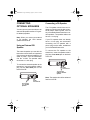
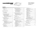
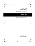
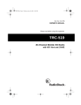
21-1598.fm Page 1 Thursday, August 5, 1999 10:52 AM
Cat. No. 21-1598
OWNER’S MANUAL
Please read before using this equipment.
TRC-498
40-Channel CB Mobile Transceiver
with Digital Signal Processor
21-1598.fm Page 2 Thursday, August 5, 1999 10:52 AM
FEATURES
Your RadioShack TRC-498 40Channel CB Mobile Transceiver is a
breakthrough in CB design technology. It includes a DSP (Digital Signal
Processor) circuit for improved audio
quality, which reduces background
noise and virtually eliminates the
whines and whistles commonly heard
on crowded CB frequencies.
Emergency Channel Switch — lets
you quickly switch to Channel 9 so you
can monitor or report emergency situations.
Your CB also has these advanced features:
Base Station Capability — lets you
use the transceiver as a base station
powered from a standard AC outlet
(with an optional power supply and
base station antenna).
DSP Switch and Indicator — turns
the DSP circuit on and off and shows
the on/off status of the circuit.
Phase-Locked Loop (PLL) Frequency Synthesizer — provides highly accurate and stable tuning.
Two Built-In Ceramic Filters — ensure superior channel selectivity and
freedom from adjacent channel interference.
Automatic Modulation Control —
prevents the transmitter signal from
over-modulating and distorting.
Automatic Noise Limiter — reduces
impulse-type noises while receiving.
Large, Illuminated, Digital Display
— clearly shows the channel number.
Built-In PA (Public Address) Amplifier — lets you use your CB as a public
address system when you add an optional PA speaker.
RF Gain Control — lets you adjust the
receiver gain to match the strength of
the received signal.
4-Step RX Signal/TX Power Meter —
shows the strength of the incoming
and outgoing transmissions.
External Speaker Jack — lets you
connect your CB to an external speaker.
Noise Reduction Switch — lets you
select one of two available noise reduction modes.
Universal Mounting Bracket — lets
you mount your CB securely in your
vehicle or on a table or shelf in your
home.
© 1996 Tandy Corporation.
All Rights Reserved.
RadioShack is a trademark used by Tandy Corporation.
Powerhorn is a registered trademark used by Tandy Corporation.
2
21-1598.fm Page 3 Thursday, August 5, 1999 10:52 AM
Note: To use this CB, you must connect a mobile or base station antenna.
Your local RadioShack store has a
wide variety of antennas. For more information, see “Connecting an Antenna” on Page 6.
We recommend you record your CB’s
serial number here. The number is on
the CB’s back panel.
Serial Number _________________
FCC INFORMATION
The Federal Communications Commission (FCC) does not require you to
have a license to operate this CB radio. However, you must know Part 95
of FCC Rules. It explains the proper
operation of a Class D citizen’s band
transceiver. We enclosed a copy of
Part 95 with your CB radio.
Warning: Do not open the CB radio to
make any internal adjustments. A CB
radio is set up to transmit a regulated
signal on an assigned frequency. It is
against the law to alter or adjust the
settings inside the unit to exceed these
limitations.
To be safe and sure:
• Never open your CB radio’s case.
• Never change or replace anything
in your CB radio.
Your CB radio might cause TV or radio interference even when it is operating properly. To determine whether
your CB radio is causing the interference, turn off your CB radio. If the interference goes away, your CB radio
is causing it. Try to eliminate the interference by:
• Moving your CB radio away from
the receiver
• Contacting your local RadioShack
store for help
If you cannot eliminate the interference, the FCC requires that you stop
using your CB radio.
This device complies with Part 15 of
FCC Rules. Operation is subject to the
following two conditions: (1) this device may not cause harmful interference, and (2) this device must accept
any interference received, including
interference that may cause undesired
operation.
Any adjustments to a CB radio must be
made by a qualified technician using
the proper test equipment.
3
21-1598.fm Page 4 Thursday, August 5, 1999 10:52 AM
CONTENTS
Installation ............................................................................................................
Attaching the Microphone Holder ....................................................................
Mounting the Transceiver ................................................................................
Connecting an Antenna ...................................................................................
Connecting the Microphone .............................................................................
Connecting Optional Speakers ........................................................................
Using an External CB Speaker .................................................................
Connecting a PA Speaker .........................................................................
Using Vehicle Battery Power ...........................................................................
Using the Transceiver as a Base Station .........................................................
5
5
5
6
7
8
8
8
9
9
Operation ............................................................................................................
Receiving Transmissions and Adjusting Squelch ..........................................
Transmitting ...................................................................................................
Using the Digital Signal Processor ................................................................
Selecting the Emergency Channel ................................................................
Using the PA Amplifier ...................................................................................
11
11
12
13
13
14
Operational Hints ...............................................................................................
Common Uses for a CB .................................................................................
Personal Uses .........................................................................................
Business Uses ........................................................................................
Maximum Range ...........................................................................................
Transmission Courtesy ..................................................................................
Using Common 10-Codes .............................................................................
15
15
15
15
16
16
17
Troubleshooting ................................................................................................. 18
Reducing Noise ............................................................................................. 20
Care and Maintenance ....................................................................................... 21
Replacing the Fuse ........................................................................................ 22
Specifications ..................................................................................................... 23
4
21-1598.fm Page 5 Thursday, August 5, 1999 10:52 AM
INSTALLATION
ATTACHING THE
MICROPHONE HOLDER
You can connect the microphone holder to either side of the transceiver or to
another location in your vehicle.
To attach the holder to either side of
the transceiver, secure the holder to
the side using the supplied screws and
lock washers.
Note: If you cannot reach behind
the mounting surface to attach the
nuts on the machine screws, use
the supplied 3 mm plain washers
and self-tapping screws.
MOUNTING THE
TRANSCEIVER
To attach the holder to another location in the vehicle, such as the dashboard, follow these steps.
1. Using the holder as a template,
mark the positions for the mounting screw holes at the desired
location.
2. At each marked position, drill a
hole slightly smaller than the supplied mounting screws.
Caution: Be careful not to drill
into anything behind the mounting surface.
3. Attach the holder at the mounting
location using the supplied 3 mm
machine screws, spring washers,
plain washers, and nuts.
The most common mounting location
for this CB is under a vehicle’s dashboard. However, if you use the TRC498 as a base station, you can place it
on a desk, shelf, or table (see “Using
the Transceiver as a Base Station” on
Page 9).
If you are mounting the CB in a vehicle, choose a location where:
• You can easily reach the CB.
• Wires and cables are clear of the
vehicle’s pedals or other moving
parts.
• The CB is not directly in front of
heating vents.
• All wires and cables can reach
their connection points.
5
21-1598.fm Page 6 Thursday, August 5, 1999 10:52 AM
Caution: If you use the CB in a vehicle, mount it securely to avoid damage
to the CB or vehicle or injury to anyone
in the vehicle during sudden starts or
stops.
Follow these steps to mount the CB
using the supplied hardware.
nuts on the bolts, use the supplied
6 mm self-tapping screws and
plain washers to secure the
bracket.
4. Attach the CB to the mounting
bracket using the supplied rubber
washers and mounting knobs.
1. Using the mounting bracket as a
template, mark the positions for
the screw holes on the mounting
surface.
CONNECTING AN
ANTENNA
2. In each marked location, drill a
hole slightly smaller than the supplied mounting screws.
Caution: Be careful not to drill
into objects behind the mounting
surface.
3. Mount the bracket to the mounting
surface with the supplied 6 mm
bolts, spring washers, plain washers, and nuts.
There are many different types of CB
antennas for mobile CBs. Each type
has its own benefits, so choose the
one that best meets your needs. Your
local RadioShack store sells a wide variety of antennas.
Note: If you are using this CB as a
base station, see “Using the Transceiver as a Base Station” on Page 9.
When you choose an antenna, keep in
mind that, for the best performance,
you should mount the antenna:
• As high as possible on the vehicle
• As far as possible from sources of
electrical noise
• Vertically
Note: If you cannot reach behind
the mounting surface to attach the
6
21-1598.fm Page 7 Thursday, August 5, 1999 10:52 AM
Once you choose an antenna, follow
its mounting instructions. Then route
the cable to the transceiver and connect the cable to the ANT jack on the
back of the transceiver.
CONNECTING THE
MICROPHONE
1. Press the tab on the side of the
supplied microphone’s plug and
insert the plug into the microphone jack on the side of the
transceiver. Be sure the tab is
aligned with the jack’s notch.
To Antenna
Cautions:
• Avoid routing the cable next to
sharp edges or moving parts,
which might damage the cable.
• Do not run the cable next to power
cables or other radio antenna cables.
2. Slide the microphone onto the
microphone holder.
• Do not run the cable through the
engine compartment or other
areas that produce extreme heat.
To achieve your radio’s maximum
range, adjust the antenna’s Standing
Wave Ratio (SWR) using an SWR
meter (not supplied).
Follow the instructions supplied with
the SWR meter and antenna to adjust
your antenna’s SWR to the lowest possible value. SWR values of 2.0:1 are
generally acceptable, with readings of
1.5:1 or lower being more desirable.
Caution: To disconnect the microphone from the transceiver, press the
tab on the side of the plug. Then pull
out the plug. Never pull on the microphone cable.
7
21-1598.fm Page 8 Thursday, August 5, 1999 10:52 AM
CONNECTING
OPTIONAL SPEAKERS
You can connect your transceiver to an
external CB speaker and/or a PA (public address) speaker.
Note: When you connect an external
or PA speaker, the CB’s internal
speaker disconnects.
Using an External CB
Speaker
The external speaker you use with the
transceiver should have an impedance
of 8 ohms and be able to handle 3 to 10
watts of power, such as RadioShack
Cat. No. 21-549. The speaker cable
must have a 1/8-inch plug.
To connect the external speaker to the
transceiver, insert the speaker cable’s
plug into the EXT SPKR jack on the
back of the CB.
Connecting a PA Speaker
The PA speaker should have an impedance of 8 ohms and be able to handle at least 5 watts of power, such as
any of the RadioShack Powerhorn® series speakers. The speaker cable must
have a 1/8-inch plug.
If your PA speaker does not already
have a 1/8-inch plug, we recommend
connecting the PA speaker with a
phono plug-to-wire cable, available at
your local RadioShack store.
To connect the PA speaker to the
transceiver, insert the speaker cable’s
plug into the PA SPKR jack on the back
of the CB.
Power
Connections
To an 8-ohm,
5-Watt or Greater
Speaker
Power
Connections
To an 8-ohm,
3- to 10-Watt
Speaker
8
Note: The speaker should be at least 6
feet from the CB.
21-1598.fm Page 9 Thursday, August 5, 1999 10:52 AM
USING VEHICLE
BATTERY POWER
Follow these steps to connect the
transceiver to vehicle battery power.
USING THE
TRANSCEIVER AS A
BASE STATION
Although this transceiver is designed
mainly for mobile use, you can also
use it as a base station with an AC
power source.
For base station installation, you need
these items:
Red Wire to
Switched
Accessory
Terminal
Black Wire
to Ground
1. Connect the red wire (with the inline fuse holder) on the back of
the transceiver to a point in your
vehicle’s fuse block that has
power only when the ignition is in
the ACC (accessory) or ON position.
2. Connect the black wire to a metal
part of the vehicle’s frame (chassis ground).
Caution: Do not connect the
black wire to a non-metallic (plastic) part, or to any part insulated
from the vehicle’s chassis by a
non-metallic part.
• 12-volt DC power supply that can
supply at least 1.5 amps (such as
Cat. No. 22-120)
Caution: Most 12-volt DC power
supplies plug into a standard AC
outlet to produce DC power.
Before connecting your CB to a
12-volt DC power supply, read
and
follow
the
instructions
included with the power supply.
• Base station antenna (such as
Cat. No. 21-967)
• Coaxial antenna cable and connectors
Note: Your local RadioShack
store carries coaxial antenna
cable and connectors.
9
21-1598.fm Page 10 Thursday, August 5, 1999 10:52 AM
Follow these steps to install the CB as
a base station.
3. Connect the transceiver’s black
power wire to the negative (–) terminal on the DC power supply.
4. Connect the transceiver’s red wire
(with the in-line fuse) to the positive (+) terminal on the DC power
supply.
Antenna
Black Wire
to Negative
Terminal of
DC Power
Supply
Red Wire
to Positive
Terminal of
DC Power
Supply
1. Mount the base station antenna
as described in its owner’s manual.
Warning: Use extreme caution
when you install or remove a base
station CB antenna. If the antenna
starts to fall, let it go. It could contact overhead power lines. If the
antenna touches a power line,
contact with the antenna, mast,
cable, or guy wires can cause
electrocution and death. Call the
power company to remove the
antenna. Do not attempt to do so
yourself.
2. Connect the antenna to the ANT
jack on the back of the CB.
10
5. Connect the DC power supply to a
standard AC outlet.
21-1598.fm Page 11 Thursday, August 5, 1999 10:52 AM
OPERATION
Caution: To prevent damage to the
CB, be sure you connect an antenna
and the microphone before you use
the CB.
Before you use your CB, you should
know how to use it effectively and
courteously. “Operational Hints” contains information that will help you get
more enjoyment from your CB.
5. Set OUT/CH9 to OUT to select a
channel other than Channel 9 (the
emergency channel).
RECEIVING
TRANSMISSIONS AND
ADJUSTING SQUELCH
1. Set CB/PA to CB.
2. Turn SQUELCH fully counterclockwise.
3. Turn RF GAIN fully clockwise.
6. Rotate the channel selector until
the display shows the desired
channel.
7. Adjust VOLUME to a comfortable
listening level.
8. To cut out background noise between transmissions, wait until
there is no signal, then slowly turn
SQUELCH clockwise until the
background noise stops.
4. Turn on the transceiver by turning
VOLUME clockwise until it clicks.
The channel display lights and the
channel appears.
11
21-1598.fm Page 12 Thursday, August 5, 1999 10:52 AM
Note: To receive very weak signals, turn SQUELCH counterclockwise. You hear noise between
transmissions, but you also hear
weak transmissions (those not
strong enough to break through a
higher squelch setting).
9. When the transceiver receives a
signal, the RX SIGNAL indicators
light. If the received signal is distorted, decrease the overall signal
level by rotating RF GAIN counterclockwise.
TRANSMITTING
Note: We recommend you try receiving before you transmit.
1. Follow Steps 1–7 in “Receiving
Transmissions
and
Adjusting
Squelch.”
2. To transmit, press the talk button
on the microphone. Hold the microphone 2–3 inches from your
mouth and speak in a normal tone
of voice, then release the talk button. The TX POWER meter lights.
10. Set the noise reduction switch to
the proper setting to eliminate the
type of noise you are hearing.
NR — to reduce background noise
TR — to eliminate tones, hetero-
dynes, whistles, and whines
Notes:
11. To turn off the CB, turn VOLUME
counterclockwise until you hear it
click. The display and indicators
turn off.
12
• Usually, all four LEDs light. If
fewer than four light, you might
have a weak power source or
improper power or antenna
connections.
21-1598.fm Page 13 Thursday, August 5, 1999 10:52 AM
• The MOD (modulation) light
flickers as you speak. If the indicator lights continuously, you
are speaking too loudly. If it
lights dimly, you might be
speaking too softly.
MOD
3. To turn off the CB, turn VOLUME
counterclockwise until you hear it
click. The display and indicators
turn off.
SELECTING THE
EMERGENCY CHANNEL
Important: Channel 9 is reserved for
motorist assistance and for reporting
emergency information about accidents, hazardous road conditions, and
so on. Always give emergency messages priority on Channel 9.
To select the emergency channel
(Channel 9), set OUT/CH9 to CH9. 9
flashes on the display, and the transceiver stays on Channel 9.
USING THE DIGITAL
SIGNAL PROCESSOR
The DSP circuit eliminates steady
tones or squeals and reduces noise in
the voice band. To activate the DSP
circuit, press DSP. The DSP indicator
lights.
Note: You can also select Channel 9
using the rotary selector when OUT/
CH9 is set to OUT. 9 still appears on
the display, but it does not flash.
To select another channel, set OUT/
CH9 to OUT. The previously selected
channel number appears on the display.
Note: The DSP circuit works only while
receiving transmissions.
To deactivate the DSP circuit, press
DSP again. The DSP indicator turns
off.
13
21-1598.fm Page 14 Thursday, August 5, 1999 10:52 AM
USING THE PA
AMPLIFIER
Your CB has a built-in PA (public address) amplifier. With an optional PA
speaker, you can turn your radio into a
mobile public address system.
Follow these steps to use the PA amplifier after you connect an external
PA speaker (see “Connecting a PA
Speaker” on Page 8).
1. Turn on the transceiver. Then set
CB/PA to PA. PA appears on the
display.
CB
PA
2. To transmit, press the talk button
on the microphone. Hold the microphone 2–3 inches from your
mouth and speak in a normal tone
of voice.
3. Turn VOLUME for the desired volume level. If you hear a highpitched squeal, adjust VOLUME
until the squeal stops.
Note: The speaker should be at
least 6 feet from the CB.
14
4. To end PA operation, turn the
transceiver off. Or, set CB/PA to
CB for CB communication.
21-1598.fm Page 15 Thursday, August 5, 1999 10:52 AM
OPERATIONAL HINTS
Like most activities, CB radio has its
customs and courtesies. The following
tips will help you get the most enjoyment from your CB.
COMMON USES
FOR A CB
Personal Uses
• Keep in touch with home while
driving to work, to the store, or to
a social activity. Let your family
know you are tied up in traffic or
that you will stop by the store on
the way home.
Business Uses
• For security officers, a CB is more
than a convenience — it is a must
for both safety and efficiency.
• Truck drivers and delivery personnel can learn road and traffic conditions and get assistance in
locating destinations. A CB radio
is also good company on those
“long hauls.”
• On construction crews, a CB radio
quickly pays for itself when you
are calling for additional materials
or coordinating the activities of different work crews.
• If you are a two-car (or more) family, CB radios are great for communicating with family members
while they are in their cars.
• Contact friends or neighbors —
find out “what’s happening” or
plan a get-together.
• Ever have car trouble or run out of
gas on the highway? What an assurance it is to be able to radio for
assistance!
• Camping, fishing, and other sports
are more fun with a CB radio.
Locate a buddy or find out “what’s
cooking” back at camp.
15
21-1598.fm Page 16 Thursday, August 5, 1999 10:52 AM
MAXIMUM RANGE
The maximum range and quality of CB
radio transmissions vary depending
on the following conditions:
• The type and quality of antenna
used
• The height of the antenna’s
mounting location — the higher
the antenna, the better the signal’s range
• The surrounding terrain — mountains and tall buildings limit the
range
• Weather conditions
• The number of nearby radios
operating on the same channel
• Standing wave ratio (SWR) between the antenna and the CB.
Note: Your CB radio’s transmission
range is generally line-of-sight.
16
TRANSMISSION
COURTESY
Please follow these guidelines of radio
courtesy when using your CB.
• Wait for a pause in someone
else’s transmission before you
ask for a break.
• If you do not receive an answer to
your call after a second attempt,
sign off and wait several minutes
before trying again.
• Do not hold down the Talk button
when you are not talking. (This is
called dead keying.)
• Assist callers with directions,
information about road conditions,
and any other reasonable requests.
21-1598.fm Page 17 Thursday, August 5, 1999 10:52 AM
USING COMMON 10-CODES
Citizen’s band operators and CB radio users have largely adopted the 10-codes for
standard questions and answers. These codes permit faster communication and
better intelligibility in noisy areas.
This table lists codes adopted by the Associated Public-Safety Communications Officers (APCO).
Code
Meaning
Code
Meaning
10-1
Your signal is bad.
10-17
En route.
10-2
Your signal is good.
10-18
Urgent.
10-3
Stop transmitting.
10-19
Contact _____.
10-4
Message received and understood.
10-20
What is your location?
10-21
Call _____ by telephone.
10-5
Relay information to _____.
10-22
Cancel last message.
10-6
I am busy or are you busy?
10-23
Arrived at the scene.
10-7
Out of service.
10-24
Assignment complete.
10-8
In service.
10-25
Meet _____.
10-9
Repeat last message.
10-10
Negative (NO).
10-26
Estimated time of arrival is
_____.
10-11
_____ in service.
10-30
Use caution.
10-12
Stand by.
10-31
Pick up.
10-13
Report road/weather conditions.
10-33
Emergency traffic. Clear the
channel.
10-14
Information.
10-34
What time is it?
10-15
Message delivered.
10-41
Switch to Channel xx.
10-16
Reply to message.
10-62
Cannot understand.
17
21-1598.fm Page 18 Thursday, August 5, 1999 10:52 AM
TROUBLESHOOTING
If at any time you suspect that your CB is not working as it should, refer to the following chart to see if you can eliminate the problem. If these solutions do not solve
the problem, do not attempt repairs or adjustment yourself. The CB should be serviced only by a qualified radio technician. If you still have problems, take your CB to
a local RadioShack store for assistance.
Symptom
Solution
Turn transceiver power on.
Microphone connected? Secure connections.
Antenna connected? Secure connections.
Too much squelch? Adjust as needed.
CB has trouble receiving.
Radio not on operating channel? Switch to active
channel.
Set CB/PA to CB.
Adjust VOLUME.
Adjust RF GAIN.
Turn transceiver power on.
Antenna connected? Secure connections.
All connections free of corrosion? Clean and
tighten.
CB has trouble transmitting.
Microphone connector loose? Firmly press in jack.
Set CB/PA to CB.
Radio not on operating channel? Switch to an
active channel.
Talk button fully pressed in? Press completely.
18
21-1598.fm Page 19 Thursday, August 5, 1999 10:52 AM
Symptom
Solution
Power connected? Secure connections.
Radio does not work at
all.
Microphone connected? Secure connections.
Fuse needs replacing? Replace with identical fuse.
See “Replacing the Fuse” on Page 22.
Set CB/PA to CB.
Cannot select a channel.
Set OUT/CH9 to OUT.
Talk button fully pressed in? Press completely.
Connect a PA speaker. Secure connections.
PA does not work.
Set CB/PA to PA.
Adjust VOLUME.
Adjust RF GAIN.
Sound is distorted.
Set the noise reduction switch to NR or TR.
Adjust VOLUME.
19
21-1598.fm Page 20 Thursday, August 5, 1999 10:52 AM
REDUCING NOISE
Because your CB is exceptionally quiet, any noise you hear is probably from
an external source in your vehicle such
as the alternator, another radio or
spark plugs.
The transceiver uses an ANL (Automatic Noise Limiter) circuit and a DSP
(Digital Sound Processor) circuit to reduce noise. However, if possible, try to
eliminate the noise by finding its
source.
You can determine the noise’s source
by turning off the engine and operating
the CB with your vehicle’s ignition set
to ACC. If the noise is reduced, the
problem is in your vehicle’s ignition or
electrical system.
Here are a few hints to help you reduce or eliminate such noise:
• Make all CB power and antenna
wires as short as possible.
• Route the power wires away from
the antenna wires.
• Be sure that the chassis ground
connection is secure.
• Replace old ignition wires with
new, high-voltage, noise suppression wires.
• Install noise suppressors on your
spark plugs, or install new spark
plugs that have built-in noise suppressors.
20
• If problems persist, check your
alternator/generator and regulator gauges. You can reduce the
noise from these sources by using
bypass capacitors at the various
output voltage points.
Your local RadioShack store has a
wide selection of noise suppression
accessories.
21-1598.fm Page 21 Thursday, August 5, 1999 10:52 AM
CARE AND MAINTENANCE
Your RadioShack TRC-498 40-Channel CB Mobile Transceiver is an example of superior design and craftsmanship. The following suggestions will help you care for
your CB so you can enjoy it for years.
Keep the CB dry. If it gets wet, wipe it dry immediately. Liquids can
contain minerals that can corrode electronic circuits.
Handle the CB gently and carefully. Dropping it can damage circuit
boards and cases and can cause the CB to work improperly.
Use and store the CB in normal temperature environments. Temperature extremes can shorten the life of electronic devices, damage
batteries, and distort or melt plastic parts.
Keep the CB away from dust and dirt, which can cause premature
wear of parts.
CLEANER
Wipe the CB with a damp cloth occasionally to keep it looking new.
Do not use harsh chemicals, cleaning solvents, or strong detergents
to clean the CB.
Modifying or tampering with the CB’s internal components can cause a malfunction
and might invalidate its warranty and void your FCC authorization to operate it. If
your CB is not performing as it should, take it to your local RadioShack store for assistance.
21
21-1598.fm Page 22 Thursday, August 5, 1999 10:52 AM
REPLACING THE FUSE
The TRC-498’s 2-amp in-line fuse
helps protect your CB from power
surges and short circuits. When replacement is required, use a 2-amp,
slow-blow glass fuse, such as Cat. No.
270-1023.
Follow these steps to replace the fuse.
1. Make sure the power source and
CB are both off.
2. Hold the fuse holder by both ends,
push the ends together, twist one
end counterclockwise, then pull
them apart.
3. Remove the old fuse and inspect
its condition. If it is blown and requires replacement, insert a new
one of the same type and rating. If
it is not blown, reinsert it.
4. Push the fuse holder ends
together and twist one end clockwise.
22
21-1598.fm Page 23 Thursday, August 5, 1999 10:52 AM
SPECIFICATIONS
RECEIVER
Frequency Coverage ................All 40 CB Channels (Class D) 26.965–27.405 MHz
Sensitivity for 10dB S/N ................................................................................ 0.5 mV
Squelch Sensitivity at Tight ........................................................................1000 mV
Overall Audio Fidelity for 450–2500 Hz .......................................................... –6 dB
Maximum Audio Output Power .................................................................... 6 Watts
Cross Modulation ............................................................................................ 50 dB
RF Gain Control Range (at 10 dB Input) ........................................................ 45 dB
TRANSMITTER
Frequency Coverage ................All 40 CB Channels (Class D) 26.965–27.405 MHz
Frequency Tolerance .................................................................................. ±100 Hz
Carrier Power at No Modulation ............................................................... 3.9 Watts
Spurious Emission ........................................................................................ –70 dB
Current Drain at No Modulation ................................................................. 1100 mA
Modulation Frequency Response for 450–2500 Hz ....................................... –6 dB
Microphone Sensitivity for 50% Modulation ..................................................... 1 mV
PUBLIC ADDRESS AMPLIFIER
Maximum Output Power .............................................................................. 6 Watts
Microphone Sensitivity for 4 Watts Output Power ........................................... 3 mV
Frequency Response for 450–2500 Hz .......................................................... –6 dB
Current Drain at Maximum Output Power ..................................................1000 mA
DSP NOISE REDUCTION
Background Noise Reduction ..................................................................... 6–12 dB
Tone Attenuation for 450–2500 Hz ................................................................. 25 dB
GENERAL
Power Requirements ................... 12 Volts DC, Negative Ground/120 V DC, 60 Hz
Dimensions (HWD) ........................... 15/8 ¥ 59/16 ¥ 83/8 inches (42 ¥ 141 ¥ 213 mm)
Weight ............................................................................................. 2 lb 3 oz (1 kg)
Included Accessories .................................. Microphone Hanger, Mounting Bracket
Specifications are typical, individual units might vary. Specifications are subject
to change and improvement without notice.
23
21-1598.fm Page 24 Thursday, August 5, 1999 10:52 AM
RadioShack Limited Warranty
This product is warranted against defects for 90 days from date of purchase from
RadioShack company-owned stores and authorized RadioShack franchisees and dealers. Within this period, we will repair it without charge for parts and labor. Simply bring
your RadioShack sales slip as proof of purchase date to any RadioShack store. Warranty does not cover transportation costs. Nor does it cover a product subjected to misuse or accidental damage.
EXCEPT AS PROVIDED HEREIN, RadioShack MAKES NO EXPRESS WARRANTIES
AND ANY IMPLIED WARRANTIES ARE LIMITED IN DURATION TO THE DURATION
OF THE WRITTEN LIMITED WARRANTIES CONTAINED HEREIN. Some states do
not permit limitation or exclusion of implied warranties; therefore, the aforesaid limitation(s) or exclusion(s) may not apply to the purchaser.
This warranty gives you specific legal rights and you may also have other rights which vary from
state to state.
We Service What We Sell
10/95
RadioShack
A Division of Tandy Corporation
Fort Worth, Texas 76102
7A6
811080500A
Printed in China