1
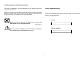
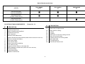
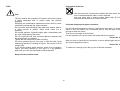
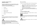
OWNER'S MANUAL Bull Shark 40xs Bull Shark 50 Tiger Shark 80 This manual must be considered as an integral part of your outboard motor and has to be kept with it, also if the motor is resold. Selva joint-stock CO. reserve the right to change its product at any moment, except for the essential specifications, which will be kept as they are. Any reference to products or details of a third party has only an informative purpose and it doesn't represent an obligation. Selva joint-stock CO. doesn't take on any responsibility concerning the performance or the employment of these products. We are glad that you have chosen a SELVA MARINE product, which means quality, technology and careful research. Your choice will give you many advantages, which you will soon learn to appreciate. Our dealers, our after-sales service and the guarantee, which you have signed, together with the observance of the information contained in this owner's manual are the essential conditions to give your recent purchase a long life. Your holiday, your favourite sport, your job, which has from today the name SELVA MARINE, will be a further moment of satisfaction. This manual belongs to Selva joint-stock CO. All rights reserved. Any partial or total reprinting without the permission is prohibited. INTRODUCTION ATTENTION Before operating this outboard motor, read this Owner's Manual carefully and completely, pay attention especially to the safety measures and rules. Your safety and other people's safety do not depend only on your ability at using the motor, but they depend also on your knowledge and on the efficiency of the motor as well as on the respect of the laws and regulations relating to the use of outboard motors. Pay attention to all the particularly important information that in this manual are distinguished in the following ways: We suggest you improve your knowledge of the motor so that you can sail with mastery and confidence. Safety measures and rules, which protect the machine If any kind of repair on the motor should not have been clearly described in this manual or if you want to order spare parts or accessories, or if you have any question about the operation or maintenance of your outboard motor, please consult an authorised SELVA MARINE service station or SELVA MARINE dealer risks. operator and other people from serious accidents or Directions or special precautions that must be taken to avoid damage to the outboard motor or personal accidents. Directions that make procedures easier or clearer. Technical information. OUTBOARD MOTOR IDENTIFICATION DATA SERIAL NUMBER RECORD This data is stamped on the label attached on the clamp bracket, as shown on the picture 1. When you receive your new SELVA outboard motor write down the serial number, it will be useful to you in case you will have to order spare parts or for reference if your outboard motor should be stolen. Write down the identification number and the model of your outboard motor in the spaces below. MODEL Make sure that the data on the label is the same as the data written in your registration book. Picture No.1 SERIAL NUMBER Do not install an outboard motor with more horsepower than shown in the certification of your boat. 3 CONTENTS GENERAL INFORMATION............................................................. 1 Introduction .................................................................................... 2 Outboard identification data .......................................................... 3 Serial number record ..................................................................... 3 Directions for use. Basic safety measures................................ 5 Specifications .............................................................................. 7 Swivel Bracket model chart ........................................................... 8 Location of main components........................................................ 8 Remote control box........................................................................ 9 Control functions............................................................................ 9 Wires' colour. ................................................................................ 10 Wiring diagrams.......................................................................... 10 Symbols ........................................................................................ 10 Starting procedure........................................................................ 22 Verifications when the motor is on ............................................... 22 Navigation................................................................................... 23 Tilt-up the motor ........................................................................... 23 Overheat warning System ............................................................ 24 Directional skeg............................................................................ 24 Running-in procedure................................................................... 25 Pre-operation checks................................................................. 25 Stopping procedure...................................................................... 26 Emergency stopping procedure ............................................... 26 Standard stopping procedure....................................................... 26 Restart after a long motionless or oil circuit cleaning ........... 26 Cleaning ....................................................................................... 27 Cleaning cooling-water passages ................................................ 27 THE USE OF THE OUTBOARD MOTOR ...................................... 12 Preliminary controls chart ............................................................ 12 Check of the supply ...................................................................... 13 Outboard motor mounting............................................................. 13 Motor fixing ................................................................................... 14 Trim angle adjusting ..................................................................... 14 Remote control box installation..................................................... 15 Steering control device mounting ................................................. 17 Battery mounting........................................................................... 18 Fuel .............................................................................................. 19 Fuel tank clamping and pipes connection..................................... 19 Automatic lubrication. M.A. ....................................................... 20 Motor oil re-fill............................................................................. 20 Use of the remote control box....................................................... 21 Starting ........................................................................................ 22 Verifications before starting the motor .......................................... 22 MAINTENANCE............................................................................. 27 Periodic inspections and adjustment charts................................. 28 Greasing chart ............................................................................. 29 Greasing and addition .................................................................. 29 Camshaft’s oil filling .................................................................. 29 Gearbox-oil change.................................................................... 30 Spark plugs .................................................................................. 30 Sacrificial anode........................................................................... 31 Replacement of the propeller ....................................................... 31 Towing ........................................................................................ 31 Storage......................................................................................... 32 TROUBLESHOOTING................................................................... 33 Troubleshooting chart .................................................................. 33 EXPLANATORY PICTURES......................................................... 35 4 DIRECTIONS FOR USE BASIC SAFETY MEASURES To use the outboard motor you must have all the requisites provided by law (physical suitability, insurance, government duties, registration, and so on). We suggest you become familiar with your boat equipped with SELVA motor in places, which are not too crowded. Use fuels and oils suitable for the engine, which are listed in the "greasing chart ". Check every so often the oil level and the fuel level. Stop the motor before every kind of maintenance or cleaning procedures, and in case of complicated maintenance take the spark-plug cap out. Picture No. 2. Taking some medicines, alcoholic drinks or drugs increase considerably the risk of accidents. Make sure that you are in a physical condition suitable for driving. Pay attention to tiredness. Before opening the top cowling, wait till the engine has cooled. Do not open the top cowling, when the engine is running. Picture No. 3. The engine operator should not let his mind wander, or be distracted or influenced by other people, things or actions,(do not smoke, eat, read, and so on.) while steering the boat. PAY ATTENTION TO THE PROPELLER The propeller is certainly the least protected part of your motor. It is therefore forbidden to get near the propeller when this is rotating. You must leave bathers, skiers and other boats users enough space to move, in order to avoid any contact with the propeller. Picture No. 4. 5 Any alteration attempted on your motor or the removal of any of its basic elements, can compromise its safety, it is against the law, and it means the immediate loss of your guarantee. The engine operator must attach the engine stop switch lanyard to his wrist when the motor is on. Picture No. 5. Observe the laws in force. Never sit on the motor. Picture No. 6. Pay great attention to the weather conditions. Listen to the weather forecast and take the warnings to the sailors into consideration. The motor must always have its top cowling on, when it is operating Picture-No. 7. Keep your boat and equipment on board in a perfect state of efficiency. Keep enough spare parts on board. Inform somebody of your route, before sailing. When you connect the fuel joint, check the proper connection For the models with automatic Oil mixer, control the proper connection of the oil joint. Picture No. 8. Prevent fires and explosions. The anti-tilt lever and the Shock Absorber lever must always be engaged while the motor is in motion. (models with Swivel Bracket or Shock Absorber) Never tilt-up the motor out of the water, while it is in motion. Picture No. 9. Before operating an outboard motor, you must know the laws and regulations relating to navigation. Avoid sudden and dangerous manoeuvres When starting or operating the engine, do not touch electrical parts and particularly the ignition-coil, the high voltage wire, the spark-plug cap and the spark-plug itself. SELVA motors are only meant as propulsion for pleasure craft. SELVA joint-stock CO. declines all responsibility for any damage to items or harm done to any person, which is due to an improper use of the motor. When opening the safety valve of the fuel tank, highly flammable vapours come out. Do not smoke, inhale or use open flames close to it. If the motor has had an accident, you should have it fully checked, before you use it again. If necessary let the SELVA MARINE authorised skilled staff have a look at it. Do not use the motor, if the damage could have compromised the sailing safety. 6 SPECIFICATIONS MODEL Bull Shark 40xs - I684A POWER FULL THROTTLE RANGE PISTON DISPLACEMENT BORE X STROKE NUMBER OF CYLINDERS ENGINE TYPE FUEL ADMISSION AVERAGE CONSUMPTION FUEL FUEL TANK MOTOR OIL MOTOR OIL TANK CAPACITY CAMSHAFT OIL CAMSHAFT OIL TANK CAPACITY IGNITION SPARK LEAD ELECTRIC STARTING SPARK PLUGS EXHAUST COOLING PROPELLER GEAR SHIFT LEVER REC.GEARBOX OIL GEARBOX OIL QUANTITY TRIM ANGLE ADJUSTING SUSPENSIONS RECOMMENDED HEIGHT OF THE TRANSOMS WEIGHT (basic models Kg.) 40HP (29.4 Kw) 5500 684 80X68 2 in a line 6 Bull Shark 50 - I684A Tiger Shark 80 - I1024A 50HP (36.7 Kw) 80HP (58.8 Kw) 5900 5500 684 1024 80X68 80X68 2 in a line 3 in a line Cycle eight 2 stroke LPDFI Direct injection 8 13 Unleaded gasoline – R.O.N. minimum 95 Separated. Lt. 23 NMMA TC-W3 - SAE J 1536 Grade 3 Lt. 3 ~ API SE, SF, SG,SH,SJ - SAE 10W-30; 10W-40 ;15W-40 500 gr. T.C.I. Computer regulated Standard with a generator 12V/ 300 W and current regulator BOSCH: FR 7D+ - CHAMPION: RC9YC - EYQUEM: RFN52LZE Bi-lateral and through propeller hub Water cooling with forced circulation caused by a pump Ratio 13/27 anti-weed with three blades and silent block incorporated forward gear - neutral gear - reverse gear API GL-5 - SAE 80W-90 480 cc. / 440 gr. 600 cc. / 500 gr. 5 positions, which you can select through a pin Silentblock at compression / traction controlled Long Shaft 508 (20 inches) 98 120 Selva joint stock CO reserve the right to change weight, construction, materials and characteristics without warning and without therefore have to change the motors, which were built previously. See picture N. 10 for the Bull Shark dimensions and picture N. 11 for the Tiger Shark dimensions. 7 Swivel Bracket model chart MODEL BULL SHARK 40 XS BULL SHARK 50 TIGER SHARK 80 SWIVEL BRACKET SHOCK ABSORBER SWIVEL BRACKET POWER TRIM GWO37 SWIVEL BRACKET POWER TRIM GWO27 LOCATION OF MAIN COMPONENTS N° 1 2 3 4 5 6 7 8 9 10 11 12 13 14 15 16 17 Picture No. 12 N° DESCRIPTION 18 19 20 21 22 23 24 25 26 27 28 Hood Hood hook back lever Motor oil tank access manifold Hood hook front lever Fuel connector Remote Control Box wires Holes to fix the motor at the transom (Models with Shock Absorber or Power Trim) Wires to connect the battery Gas control cable Gear control cable Plate to connect the steering Trim switch on tray Support to lift the motor on the right side Shock Absorber control lever (Models with Shock Absorber) Directional Skeg Anticavitation plate Gearbox oil-level hole 8 DESCRIPTION Gearbox oil-drain hole Water inlet for speed meter Water inlet for cooling Anodes Propeller Water inlet to clean the cooling circuits Motor lift on the left side Indicator tube for the cooling water Motor data label Tim-adjusting pin Anti-tilt hook control lever Neutral gear accelerator control lever It allows to control the accelerator when the clutch is in the neutral position, to increase the number of r.p.m. you must pull it up. REMOTE CONTROL BOX MAIN COMPONENTS 1 CONTROL LEVER 2 NEUTRAL LEVER FIXING ROD 3 NEUTRAL GEAR ACCELERATOR CONTROL LEVER 4 STARTING KEY 6 SECURITY SWITCH 7 TACHOMETER CONNECTOR 8 ELECTRIC MOTOR WIRING 9 GAS CONTROL FLEXIBLE WIRES 10 GEAR CONTROL FLEXIBLE WIRES 11 SCREW REGULATING CLUTCH AND ACCELERATOR 12 TRIM SWITCH Starting key Turning it in a clockwise direction till the position ON the electric circuit operates, continuing with the rotation till the START position the motor starts. If you release the key from the START position, it returns automatically to the ON position. To switch of the motor put the key in the OFF position. Security switch Insert the nippers of the wire to be bound around the pulse. In case of necessity give a blow to the wire and the motor stops. The motor doesn't start if the nipper of the security switch isn't connected. Tachometer connector To be used to connect the tachometer. Picture No. 13 Wiring connector To be engaged with the motor connector to get the electrical connection. CONTROL FUNCTIONS (remote control box)) Power Trim switch Switch to control the motor's inclination. Control lever It controls the selection of the forward gear, of the reverse gear and of the acceleration Neutral lever fixing rod It fixes the control lever in the neutral position end has to be pulled up to select the forward gear or the reverse gear. 9 WIRING DIAGRAMS Wires' colour CONTROL FUNCTIONS Motor G GL GB L O LBl R P Gy RBl BLb PR W WB WG WY Y YG YL YB YR Hood Hook. Device to fix the hood. To release it you have to turn the two handles counter clockwise. Picture No. 14 Fuel connector Inserting the connector you connect the fuel hose. Picture No. 15 Trim switches. (only models with Trim Tilt) It allows the insertion of the Trim Tilt device directly from the motor. Picture No. 16 Support to lift the motor To keep the motor in tilt position, turn the support and place it on the bracket. Picture No. 17 Shock Absorber control lever Rising the lever you can tilt the motor. It has to be lowered before beginning the cruising. Green Green Bleu Green Black Bleu Orange / Light Bleu Red Pink Grey RedBlue BlackLighBlue PinkRed White White Black White Green White Yellow Yellow YellowGreen Yellow Bleu Yellow Black Yellow Red Electrical wiring diagrham Picture No. 18 (Picture No. 21) 1. Spark plug 2. Ignition coil cylinder #1 3. Ignition coil cylinder #2 4. Ignition coil cylinder #3 5. Starter solenoid 6. Generator 7. Oil Tank 8. Trim Tilt Switch 9. Trim Tilt Switch (Remote Control Box) 10. Starting Panel 11. Buzzer Trim adjustment pin. It can b inserted in the brackets in different positions allowing a correct adjustment of the trim. Picture No. 19 Directional Skeg The directional skeg allows to balance the left and right turn efforts. It acts also as an anode to avoid the electrochemical corrosion of the motor. Picture No. 20 10 12. Emergency cut-off switch SYMBOLS 13. Engine temperature Sensor (ETS) 14. Air temperature Sensor (ATS) 15. Throttle position sensor (TPS) 16. PC Connexion 17. Crankshaft sensor 18. Fuel injector cylinder #1 19. Fuel injector cylinder #2 20. Fuel injector cylinder #3 21. Electrical fuel pump 22. Main relay 23. Fuel pump relay 24. Temperature alarm relay 25. Power trim and tilt UP relay 26. Power trim and tilt DOWN relay 27. Fuse 10 A 28. Fuse 20 A 29. Fuse 15 A 30. ECU 31. Neutral switch 32. Trim pump 33. Neutral microswitch 34. Rectifier regulator 35. Battery 36. Motor tachometer 37. Starter motor 38. Fuse 1 A Engine 1 - A serious risk is present. The machine operator must read and follow the instructions in the manual. 2 - Outboard motor free lock. 3 - Warning against fire-hazard (fuel tank) Picture No. 22 Picture No. 23 Remote control box 1- Reference to control lever position 2- Reference to the starter key position 3- Cut-off switch 11 THE USE OF THE OUTBOARD MOTOR PRELIMINARY CONTROLS CHART DETAIL Complete supply Right installation CHECK DESCRIPTION PAGE Check that the motor supply includes all the components that are in the detailed list. 13 Check the proper installation of your motor (the centre of the transom). 13 Check the proper mounting height of your motor. 13 Check the tightness of the clamp screws and of the hand levers. Check the proper installation of the remote control box. Battery and fuel tank Check the position of the battery and fuel tank from detailed list. Fill up Check that the fuel, the motor oil and the camshaft oil are conform to the specifications. Fuel hose connection Check the proper connection of the fuel hose. Oil circuit fill up Check that the oil pipes are full Check the equipment on board Check that you have on board everything necessary to face a possible emergency. 14-15 15 18 - 19 7 19 20-25-26 If you ever have a question about the operation of your outboard motor, or if you should find any kind of anomaly, please consult a SELVA MARINE dealer. The time which is needed to check your motor is very modest, but the safety, that you obtain from it is enormous Before leaving always check your motor to make sure that it is in a perfect state of efficiency, check its proper and safe functionality. Failure to check as shown in the chart could result in severe injury to people or damage to the boat. 12 Outboard motor mounting. Check the supply. A good position of the motor on the transom is very important to have an appropriate trim angle and therefore to obtain a good performance from your boat When you receive your motor check that: • • • the packing is not damaged the supply corresponds to the detailed list 1 the entire motor 2 3 4 the steering rod with nuts fuel tank with the fuel hose and quick reverse connection remote control box 5 nuts kit to fix the motor on the transom 6 Kit to fix the remote control box 7 rope for cut-off switch 8 rope with handle for the emergency starting 9 declaration of conformity E.E.C. 10 certificate of guarantee 11 use and maintenance manual 12 tools kit The motor has to be mounted on the centre line of the stern belt. To have the optimum mounting height of the outboard motor, you must mount it so that the anti-cavitation plate is between the bottom of the boat and a level of 2 cm below it and it is parallel to it. If the mounting-height is too high, cavitation tends to occur and consequently there will be a falling-off in the performance and a probable overheating of the motor. If the mounting-height is too low, the water-resistance will increase and thereby reduce engine efficiency. The motor must be vertical to the water surface and the bracket mounted on a flat even surface and should be fully supported by the top edge of the transom. If the bracket is not fully supported or, if the transom height is too low, a hard wood block should be securely fitted between the bracket and the transom. Picture No. 25 there is no evident damage. If there is a damage or parts are missing, you must inform immediately and in details the forwardingagent, SELVA joint stock Co. or its area agents. Picture No.24 13 MOTOR FIXING TRIM ANGLE ADJUSTING Model with Swivel Bracket The trim angle is the inclination angle, that should be given to the motor in order to obtain an optimal performance from your boat. After having put the motor in the correct position, clamp the screws of the levers. Then make two holes in the transom in correspondence of the holes in the fixing brackets. Apply some dope on the holes made and on the screws to be used to fix the motor (which are with the motor). Insert the screws and the washers so that the nuts are inside the boat. Then clamp very well. An improper trim angle does not only affect the performance of your boat, but can also cause loss of control, which means danger for the people on board. Models with Shock Absorber-Power Trim While sailing the motor should be perpendicular to the water surface, but the trim angle can be 3 degrees to 5 degrees. After having found the correct fixing place of the motor, make four holes in the transom so that they are in correspondence with the holes in the fixing brackets. Then apply some dope on the holes made and on the bolts (accessories). Insert the bolts from outside of the transom and screw the bolts clamping them very well. Picture No. 26 If the trim angle is made too great, the buoyancy centre of the boat will shift towards the stern. In this condition, and if the stability moment at the bow is large, the boat will tend to "porpoise". If the trim angle is insufficient, the bow may "plough", making the boat unstable. When the boat is in stable trim it remains parallel to the water. Use only bolts, nuts and washers which are in the motor packing. If you need to use other components, be sure that they are of the same quality regarding the material and strength. Tighten the bolts and check the tightening of bolts and levers after running the motor. Trim Adjusting - models with Trim The trim-angle adjusting is automatically made and regulated through the utilisation of the Trim. Picture No. 27 For the models with Shock Absorber and Power Trim, the two screws that are in the brackets are used only to keep the motor while fixing it and you have to take them away when you've fixed it. We suggest you to ask for the help of skilled people to make he operations over described. 14 Trim-angle adjusting - models with Shock Absorber Position of the remote control box Release the Shock Absorber through the control lever. Tilt the motor and keep it in this position through the tilt-supports. Insert the trim-adjusting pin in the position of correct trim. Lower the supports and place the motor in the original position. Fasten the Shock Absorber releasing the control lever. Picture No. 28 Normally the remote control box is supplied to be in positioned on the right. If you need to have it on the opposite side, ask your dealer. When positioning the remote control box pay attention that the control lever can be gripped and operated comfortably and without obstacles. Even the cables must be put in order not to have any obstacle on their patch and must not get in the way of the passengers. Be sure that the cables are long enough and that they can't get entangled when the steering-wheel is operating Picture No. 29 REMOTE CONTROL BOX INSTALLATION To install the remote control box and the cables we suggest you contact an official dealer SELVA MARINE. We suggest you contact this dealer also for the control device installation. If the cables aren't correctly installed, they can get entangled causing the loss of control of the boat. An improper installation of a remote control box may cause a sudden and unexpected loss of control, of the boat. In case or doubts about the remote control installation, ask your SELVA MARINE dealer. 15 Side of the remote control box To connect the control cables to the box you have to follow the following instructions: Never bind or entangle the cables of the remote control box. They mustn't be bound with a bending ray inferior to 300 mm. (12 feet). • Remove the lower cover (6) of the remote control box by unscrewing the two screws. • Put the control lever (1) in neutral position. • Screw completely the gear to connect the remote control box (9) to the threaded extremity of the cables and fix them with the counternut, paying attention not to tighten it too much. • Put the head of the gear-control lever in the pawl of the gear lever (10) and insert the retaining ring (8). CONTROL CABLES CONNECTION • Insert the head of the gas-control cable in the pawl of the accelerator lever (11) and insert the retaining ring. To make the connection of the control cables you have to use the Kit K44 (included in the supply) made by: • Fix the sheathing of the cables inserting the sheathing-retainer in its housing. • Screw the lower cover. The cables aren't included in the supply of the motor. They must be of the type C2. Picture No. 30 Nr " " " " " " " " " " 4 2 4 4 2 4 2 3 3 3 1 Remote control heads Sheath retainer bolts Screws TC Phillips M5x20 Self-locking nuts M5 Split pins Washers Grower M5 Seeger rings Screws TSPTC M6x100 Washers M6 Self-locking nuts M6 Clamp Picture No. 31 Remote control box fixing After having connected the remote control cables, place the box in the determined position and fix it through the accessories (3 screws M6x100 3 washers M6 - 3 self-locking nuts M6) included in the Kit K44. Picture No. 32 16 Another adjustment can be made unscrewing the remote control box heads. When you've finished the adjustment fix the heads with the counter nuts. Picture No. 33 Connection from the side of the motor To connect the control cables to the motor follow the following instructions: • Put the remote control lever in the neutral position. Lower completely the gas control lever in neutral position • Insert the cables in the tray, letting them pass through the holes made on the right side of the fuel connector. • Screw the remote control heads at the end of the two cables. STEERING CONTROL DEVICE MOUNTING • Insert the heads in the pawls of the gears and accelerator levers, paying attention not to muddle the cables. • Fix the sheath of the accelerator control cable putting the sheath retainer in correspondence of the groove of the sheath and screwing it (using the two screws TC Phillips M5x20 and the two self-locking nuts of the Kit K 44) in the holes made in vertical position on the support of the remote control box sheath retainers. • Fix the heads on the pawls using the split pins Insert the control cable in the tube brackets union. Fix one extremity of the longitudinal rod of control of the steering to the steering fixation plate, using the apposite nut, bolt and washer. Then fix the other extremity of the rod to the cable of control through the nut and the washers. Insert the sheet-retainer 2 in the control cable. Insert the cable in the tube brackets union, then on the cable itself and then the washer 4 and the ring 5. stop the sheet in the bracket tube screwing the rings 2 and 5 completely (see the positions of the bolts shown in the picture). • Make again the same operation for the gears control cable screwing the bolt in correspondence of the holes made horizontally on the support. • The sheath retainer support must be fixed in two different positions according to the length of the control cables. At the end of the operations control the correct functioning of the remote control box. 1 2 3 4 Control cable Ring Tube bracket union Washer A B C Steering plate Steering arm kit Control cable end 5 Ring nut 6 Control cable end 7 Steering link arm kit 8 Steering plate Picture No.34 17 BATTERY MOUNTING Connecting the battery • Before connecting or disconnecting the battery leads turn the switch key in the anti-clockwise direction, to avoid risks of electric shock, fire or explosion. It is important to install with the battery the battery disconnect switch. (not included) Mount the battery in a dry, well-ventilated, vibration-free location in the boat. Recommended battery type: Connect the red lead to the positive terminal (+) first; then connect the black lead to the negative terminal (-). Red lead Black lead Battery Battery disconnect switch • Wear protective eye gear when handling or working near batteries. • If any battery electrolytic fluid spills onto your skin, flush with water. • If you should get battery electrolytic fluid in your eyes flush with water for 15 minutes and get immediate medical attention. • If you should swallow battery electrolytic fluid, drink large quantities of water or milk followed by milk of magnesia, beaten eggs or vegetable oil. Get immediate medical attention. Batteries also generate explosive hydrogen gas. Therefore avoid operating in areas which are not well-ventilated or near fire, spark, or open flames. DO NOT SMOKE when charging or handling batteries. Minimum rated capacity (20HR/IEC): 12V 70 A.h Minimum cold cranking (CCA/EN): 430 A at -18°C (-0.4 °F) 1234- Battery electrolytic fluid is dangerous; it contains dilute sulphuric acid and therefore is poisonous and highly caustic Always follow these preventive measures: Avoid bodily contact with electrolytic fluid as it can cause severe burns or permanent eye injury. KEEP BATTERIES AND ELECTROLYTIC FLUID OUT OF REACH OF CHILDREN. Picture No. 35 To disconnect the battery, disconnect the black lead first. It is important to disconnect the battery connection with the battery disconnect switch only when the engine is stopped. The disconnection of the battery when the engine is running can make serious damages to the engine. 18 Preparation of the fuel FUEL Use only pure fuels, conserved in suitable and clean tanks, that aren't contaminated with water or other materials. Use only petrol with a octane number higher than 95 N.O. Research and that does not contain alcohol. Fuel The fuel used for the propulsion of internal combustion engines is highly flammable and, in certain cases can become explosive. Refuelling and maintenance operations must be done in a wellventilated area and with the engine stopped. Do not smoke while refuelling, keep away from sparks, flames, or other sources of ignition, which could cause fire or explosion. Do not spill gasoline. If gasoline spills, wipe it immediately with dry rags, before starting the motor . Do not overfill the fuel tank, because gasoline expands with the heat and the sun radiation. Tighten the filler cap securely after refuelling. Do not let gasoline get into your eyes or onto your skin. Avoid swallowing gasoline or inhaling its vapour. Do not pour fuel off using a pipe. If you should swallow some gasoline, inhale a lot of gasoline vapour, get some gasoline in your eyes, or if any gasoline spills onto your skin, get immediate medical attention. Fuel tank clamping and pipes connection Put the fuel tank horizontally in the hull, anchored to the bottom, in a place where it does not hinder your movements and so that the pipe is long enough to reach the motor. Then connect the pipe to the fuel joint. For this operation you have to insert the female fast fuel connector. Picture No. 36 Now you have to check the full connection, is secure pulling lightly the joint (do not pull grasping the hose). Picture No. 37 To release it is enough to pull the ring nut of the fast connector. Keep out from children reach. 19 AUTOMATIC LUBRICATION M.A. ( Multipoint Autolube) Motor oil refuelling To refill the oil system please respect the following procedure: The motor is equipped with the automatic lubrification system “Multipoint autolube” that provide the adequate oil quantity on in relation to the motor running speed. The device is composed by the following parts: • 1. Oil pump. 2. Control levers. 3. Delivery oil pipes. Turn the access manifold cap in counter clockwise direction till the complete release and leave it on the top cowling.. • To access the oil tank unscrew the refill cap, remove it and place it on the top cowling. • Pour carefully the oil inside the tank and when the operation is completed close both the manifold and tank caps. Fig. 39 4. Feeding oil pipe. LOW LEVEL WARNING ALARM 5. Oil filter on the feeding oil pipe The motor is equipped with an acoustic device to warn you about the low motor oil level. 6. Oil tank Fig. 38 When the oil low level alarm start working, the buzzer gives out an uninterrupted sound meaning that it is necessary add oil to the tank. At motor receiving fill the oil tank with motor oil according to the technical specification indicated in the special section of this manual. Check that the oil used to re-fill is in line with the given specifications. It’s necessary to use synthetic based oil in accordance to the specifications indicated in this manual. Before filling the tank it’s necessary to verify that the same is perfectly clean and dry from water. The presence of water in the tank may casue serious damages to the engine. 20 USE OF THE REMOTE CONTROL BOX Accelerating when neutral gear is selected Leaving from the position N of the control lever, to position in forward gear you have to lift the retainer lever and to put the control lever in position F. To open the throttle when the neutral gear is selected (gear lever in N position), you have to use the neutral gear lever and turn it up. Picture No. 41 The insertion of the gear is indicated by a release of the movement. if the lever goes on in its travel, the accelerator begins to operate. At the end of the travel of the lever there is the maximum opening of the throttle valve. To select the reverse gear you have to put the control lever in position R . If, when the gear is selected, the lever goes on in its travel, the acceleration phase begins Before selecting the gear you always have to put the gas lever at the neutral position, in repose position (completely down). N F R a b c d The gas lever can be actionned only when the control lever is in position N. The control lever can be actionned only when the gas neural control lever is at repose position (completely down). Neutral position (neutral) Forward gear (forward) Reverse gear (reverse) Travel to select the forward gear Acceleration travel if forward gear is selected Travel to select reverse gear Acceleration travel if reverse gear is selected Picture No. 40 For the models with Power Trim: on the control lever of the remote control box there is the switch. If you push on the upper part of it the motor will tilt, while if you push on the lower part of it the motor will drop. Picture No.42 The travel of the acceleration when the reverse gear is selected is mechanically limited on the motor. To avoid damages not to force on the control lever. The micro switch 8 prevents the motor from starting when the gear is selected. 21 Verifications when the motor is on STARTING Just after starting the motor, you should make sure that: Verifications before starting he motor -after 5/10 seconds some water runs out from the cooling-water pilot holes. The indicator, placed at the entrance of the circuit, provides only for the proper operation of the pump and not for the circulation of water in the head and in the cylinder. That means that possible shortages will not be indicated. If water does not flow from the pilot-holes, check to see if the water inlets are blocked. Picture No. 45 Check that the hood is correctly locked. Check the correct insertion of the fuel connection. Check the insertion of the cut-off switch. Picture No. 43 When the fuel tank connector is inserted some vapours of fuel come out. It's highly flammable and its vapours are explosive, and therefore you may not smoke during this operation and you have to stay apart from flames and sparks. - that you do not hear any strange noise - that the control members work correctly Starting procedure (when the motor is cold) - the security devices are efficient. Loose the safety valve on the fuel tank. Using the hand-pump fill up the fuel admission pipe with the fuel (When the pump is hard, it means that you've achieved your aim). Place the control lever in the neutral position. Turn the starting key till the ON position and wait for 3-5 seconds. Turn the starting key till the start position, keeping it into this position not more than 5 seconds. When the motor starts release the key, that will be in position ON If the motor doesn't start, after several attempts look at the troubleshooting table. Picture No. 44 22 Turn clockwise the trim release screw, that you can reach through the hole on the left bracket. Lift the motor by hand and fix it in this position pushing towards the high the motor's supports and turning the trim release screw in counter clockwise direction at the end of its stroke. Lower it and accompany it while lowering it and secure it in this position turning the trim release screw in counter clockwise direction. Picture No. 48 CRUISING Responsibility during the navigation. The operator is responsible for the proper running of the boat and for the safety of the people on board. Everybody must read this manual before cruising. Show all the passengers the location of the safety equipment and the way to use it. Teach one of your passengers , how to pilot the boating an emergency. Familiarise yourself with the laws and regulations in force where you want to sail. Trim adjusting (with Power-Trim device unusable) Tilt-up the motor (model with Shock Absorber) To adjust the trim when the Trim device is not operating, follow these instructions. If the motor is in tilt position (lifted) you have to: Release the Shock Absorber using the control lever. Tilt-up the motor and secure it through the motor-lift supports. To bring it back to the original position you have to lift lightly the motor, lower the motor's supports and bring it till the original position. Fix the motor using the control lever. Picture No. 46 Tilt-up the motor (model with Power Trim) • Insert the trim-pin in that position that allows a correct trim. • Turn in a clockwise direction the trim release screw. (in this way the pressure on the piston of the tilt will discharge and the motor is no more supported) It must be accompanied till it's lowered. • When the motor leans on the adjustment pin you have to turn the trim release screw in a counter clockwise direction till the end of the stroke, paying attention not to force too much. • The motor is fixed in the correct trim position and it's possible to cruise. Picture No. 49 You tilt up the motor using the Power Trim device If you want to keep the motor in tilted position for a long period you have to secure it using the motor's supports. They must always be fixed before the Power Trim device operates. Picture No. 47 If the motor is in cruising position you need to follow the same operations turning it over by hand. These operations must be made when the motor is off. If the motor is in tilt position, it begins to lower as soon as you turn the release screw in a clockwise direction. If the battery is discharged or there is a failure in the electrical system of the Power Trim, it's however possible to tilt the motor up following the following instructions: 23 Overheat warning system Directional skeg The directional skeg allows to balance the turn effort. When the boat tends to turn right, turn the directional skeg right (direction A in the picture) The engine is provided with an overheat warning device Before the engine becomes too hot, the engine speed is reduced to 3000 RPM by the E.C.U. If the overheat warning system operates, proceed as follows: Check that water runs out of the pilot hole. If OK, keep the engine at low speed for about five minutes. Then avoid overloading the engine. If no water or just a little runs out from the pilot hole, stop the engine, tilt it up, as shown in this manual and check the water inlets for blockages. If blocked, you must clean them, bring the motor back to the home position and start it and run it at low speed for about five minutes; check that water runs out of the pilot hole. If after having done all this, you start the engine and no water runs out of the pilot hole, stop immediately the motor and contact a SELVA MARINE dealer. And if the boat tends to turn left, turn the skeg left (direction B in the picture) The directional skeg is also an anode to avoid the electrochemical corrosion of the motor. Not to compromise this function you never have to paint it and it must be properly connected to the motor ground. After the installation or the replacement of the skin you always have to make some verifications of its correct operating. An improper adjustment of the directional skeg might cause control difficulties and a loss of control of the boat. Picture No. 50 In case of over heating problem, the buzzer gives out an uninterrupted. Always switch the motor off before tilting it up. Before beginning the cruising again, check that the motor is fixed in the correct trim position. Never keep the motor on if no water runs out of the pilot hole. 24 Avoid operating at full throttle for more than 5 minutes at a time. Let the engine cool between full-throttle runs. Vary engine speed occasionally. BREAKING IN (RUNNING-IN) PROCEDURE Your new engine requires a period of break-in (running-in) to allow mating surfaces of moving parts to wear-in evenly. Correct break-in (running-in) will help ensure proper performance and longer engine life. 5) After the first 10 hours: Operate the engine normally. PRE-OPERATION CHECKS Failure to follow the break-in (running-in) procedure may result in reduced engine life or even severe engine damage. If any item in the pre-operation check is not working properly, have it inspected and repaired before operating the outboard motor. Otherwise, an accident could occur. Do not use pre-mixed fuel in this engine as it may cause carbon deposits on the fuel injector thereby causing engine trouble. Do not start the engine out of water. Overheating and serious engine damage can occur. Follow the instructions for breaking-in / running-in carefully. Verify that the oil pipes are full. In case of air presence in the oil pipes, stop immediately the engine and consult your Selva dealer. NOTE: Break-in (running-in) time:10 hours Run the engine under load (in gear with a propeller installed) as follows. 1) First 10 minutes: Run the engine at the lowest possible-speed. A fast idle in neutral is best. 2) Next 50 minutes: Do not exceed half throttle (approximately 3,000 r/min). Vary engine speed occasionally. If you have an easy-planing boat, accelerate at full throttle onto plane, then immediately reduce the throttle to 3,000 r/min or less. 3) Second hour: Accelerate at full throttle onto plane, then reduce engine speed to three quarter throttle (approximately 4,000 r/min). Vary engine speed occasionally. Run at full throttle for one minute, then allow about 10 minutes of operation at three-quarter throttle or less to let the engine cool. 4) Third through tenth hours: 25 RESTART AFTER A LONG STOP PERIOD OR AFTER EMPTING THE LUBRICATION CIRCUIT STOPPING PROCEDURE Emergency stopping procedures. After a long stop period or after empting the lubrication circuit, it’s necessary to fill up the oil lines removing manually any eventual presence of air in the circuit that may casue serious damage to the engine. In an emergency you can stop your motor by pulling the engine stop switch lanyard. To start the motor again you have to install again the lanyard's lock plate on the engine stop switch. Picture No. 51 Before operting the motor check that the oil delivery pipes are full. Stopping in normal conditions Place the control lever (remote control box) in the neutral position " N ". Turn the switch key till the OFF position. Picture No. 52 If you don’t care about this procedure, it could be dangerous for the motor and compromise its functionality. 26 CLEANING MAINTENANCE Cleaning outside Before doing any kind of maintenance or check operation, switch off the engine and wait till it has cooled down, then remove the spark plug cap, in order to avoid an accidental starting. Pay attention to the motor parts, which are still hot, so that you do not burn yourself. SELVA motors don't need much cleaning; to clean the painted parts use a cloth soaked with water Do not use flammable solvents. Some maintenance operations must be carried out by qualified staff. Contact SELVA MARINE after-sale service. Cleaning cooling-water passages Every now and then after using, clean the cooling-water passages, in order to remove mud and salt, so that they do not affect the performance of your motor. The following chart lists the periodic maintenance operations to do on your motor. You can carry out this cleaning operation in two different ways: The pointed out operations must be done by qualified staff. 1 - Immerse the outboard motor without the propeller in a tank filled up with fresh-water, make sure that the water level is over the height of the water inlets, so that no irreparable damage could be caused to the motor. Shift the gear-shift lever into neutral " N ". Start the engine and run at low speed for a few minutes. 2 - Connect a pipe of fresh-water to the hole for the engine cleaning joint plug ( use the proper joint available in the fittings series ). Stop the water inlets. Shift the gear-shift lever into neutral. Start the engine and run at low speed for a few minutes. While cleaning the cooling water passages make sure that water always circulates in the passages, checking its running out of the pilot hole. Picture No. 53 27 PERIODIC INSPECTIONS AND ADJUSTMENTS (Running hours) (Running hours) OPERATIONS TO PERFORM INITIAL 10 50 THERE AFTER EVERY 100 100 10 Out of season OPERATIONS TO PERFORM INITIAL Check the ignition system Inspection of the conditions of the fuel hoses. If necessary replace them. Check the head screws and the adjustment to the correct torque. Check the fuel hose joints for leaks If necessary replace them. Check the efficiency of the water pump and of the cooling system Check the proper working of the fuel filters Replacement of impeller Replacement of fuel filters Check the gearbox-oil level Check the proper working of the electrical fuel pump Check the wear of the anode. If necessary replace it. Check the presence of oil in the delivery pipes and verify its consumption. Check the trasmission belt. If necessary replace it Check the motor oil filter functionality. Check the condition of the propeller. If necessary replace it. Motor oil filter replacement. Check and if necessary clean the motor oil tank. Check and clean the camshaft’s oil tank. Check and if necessary clean the vapor separator body Check, clean and adjust the spark-plugs. If necessary replace them. 28 50 THERE AFTER EVERY 100 100 Out of season PERIODIC INSPECTIONS AND ADJUSTMENTS Greasing and additions GREASING CHART GREASE POINTS Gearbox Camshaft Bushes of the clamps pipe Cowling lock levers pins GREASE THAT MUST BE USED API GL-5 SAE 80 W 90 MIL -L 2105 C API SE, SF, SG, SH SAE 10W-30 10W-40 15W-40 SPRAY LUBRICANT SPRAY LUBRICANT The part, which must be filled with oil, are the camshaft oil tank and the gearbox. GREASING FREQUENCY Camshaft oil filling SALT WATER Check the level after the first 10 running hours. Afterwards every 50 hours. If necessary add till the marked point. Change the gearbox-oil after the first 20 running hours and afterwards every 100 running hours; and anyway each season. Check the oil level every 6 months. If necessary add till the marked point. Change the oil after the first 10 running hours; afterwards every 100 hours, anyway change the oil once per season. 60 days 30 days FRESH-WATER 60 days 30 days Tie rod carburettor levers WATERREPELLENT MARINE GREASE 60 days 30 days 60 days 30 days Propeller shaft WATERREPELLENT MARINE GREASE 60 days 30 days Clamp screws WATERREPELLENT MARINE GREASE Gear-shift lever SPRAY LUBRICANT 60 days 30 days When delivered, the camshaft’s oil tank is empty, before operating the engine fill it with oil. The oil must agree with the characteristics listed in the greasing chart, and must comply with the quantity pointed out in the technical detailed list. Camshaft oil change To change the camshaft’s oil do as follow: Keep the motor in vertical position. Remove the plastic coner around the shaft of the engine Place a container to collect the used oil under the drain-oil hole Take out the oil-level plug and the oil drain-plug. Wait until the oil has drained completely, (during this operation you must check, if water or other foreign bodies are to be found in the drained oil. They are signs of anomalies which must be identified and repaired by qualified staff, before using the motor again). Insert the oil drain plug and check the seal. Throught the filling hole fill the oil. Insert and tighten the oil-level plug. The used oil must be given to the proper collecting centres or to a SELVA service point. Picture No. 54 29 Gearbox-oil change Spark-plugs Selva supply the motor already with the oil, which the user will have to change completely after the first 20 cruising hours After this change you must check its level every 50 hours and change it every 100 hours, and anyway each season The spark-plug must be often inspected because heat and deposits affect its efficiency so that the performance of the motor will be affected too. To change the oil do as follows : Keep the motor in vertical position. Place a container to collect the used oil under the gearbox. Take out the oil-level plug and the oil drain-plug. The inspection of the spark-plug must be done when the engine is not running and it has cooled down. It is very important to check, that the part made of porcelain is not damaged because this could allow external sparks, which could lead to explosion or fire. They have a different size and after the oil change they must be replaced in their proper seat. To remove the spark-plug use the supplied spanner; using an abrasive brush, remove any depots, then check the wear condition and the sparkplug gap ( the gap must be 0,6 mm, to measure it use a thickness gauge ) Wait until the oil has drained completely, (during this operation you must check, if water or other foreign bodies are to be found in the drained oil. They are signs of anomalies which must be identified and repaired by qualified staff, before using the motor again). Inject the oil into the oil drain-plug hole. If the spark-plug is badly worn you must replace it with a new one which must agree with the characteristics listed in the specifications chart. The oil must agree with the characteristics listed in the greasing chart, and must comply with the quantity pointed out in the technical detailed list. The spark-plug torque is 20 Nm ( ~ 2. kgm). If a torque-wrench is not available, you can obtain a good estimate of the correct torque turning the spark-plug completely by hand and then turning it with the spanner, a new spark-plug must be turned ~ 90° and an old one 15° ÷ 20°. Insert and tighten the oil-level plug and the oil drain plug. Picture No. 55 Replace the spark-plug cap, checking that it is correctly fitted and then replace the top cowling. Picture No.56 The used oil must be given to the proper collecting centres or to a SELVA service point. 30 Replacement of the Propeller Sacrificial anode. The propeller is one of the components, which have a great influence upon the performance of the motor. An unsuitable or damaged propeller can cause serious damages to the motor besides reduce the performance. To protect the motor against electrochemical corrosion, due to the presence in its structure of many different materials, a sacrificial anode has been applied. The anode will be subject to a strong corrosion, so you have to remove the scales from the surfaces of the anode periodically. For an careful choice of the propeller consult a SELVA MARINE service centre. Remove and replace the propeller do as follows: Failure to clean it, will affect its effectiveness. • wait until the motor has cooled down and remove the top cowling; • remove the spark-plug cap, to avoid an accidental start; • protect your hands using strong gloves and insert a wooden lump between the propeller blades and the anti-cavitation plate, to keep the propeller still. • remove the split pin, the blocking nut, the washer, the propeller and the propeller shoulder. • spread the propeller shaft with water-repellent grease; • assemble everything in the opposite direction paying attention to clamp the nut until you reach the position that allows the insertion of the split pin in the hole made in the propeller shaft. • insert the split pin and fix it widening the end. Do not paint the anode, for this would render it ineffective. When the corrosion compromise its functionality, you have to replace it. Picture No. 57 Picture No.58 Before making the maintenance operations on the motor, take away the spark plug caps to avoid accidental starting. Towing The motor should be towed in the normal running position. Avoid towing with the tilt-support lever only, but use a motor support device. 31 Fuel tank. Storage Store the fuel tank in a well-ventilated place, not in direct sunlight. To help the endurance of your motor, you must carry out properly the following storage operations: • Clean the motor and the cooling-water passages. • Remove the fuel-line connections from the motor. • Change the fuel filter. • Empty the float chamber of vapour separator tank. • Remove the spark-plug and put engine-oil into the hole; turn the flywheel by hand to distribute the oil in the cylinder; replace the spark-plug. • Check the motor oil tank and if necessary clean it. • Change the motor-oil filter. • Change the camshaft oil, check the camshaft’s oil tank and if necessary clean it. • Change the gearbox-oil. • Check the screws torque. • Grease all the components as shown in the greasing chart. • Inspect the anode. • Store the motor in vertical position, in a dry and not too cold place. For a long period of storage, drain the fuel from the tank Battery Disconnect both battery leads from the battery, disconnecting the black lead from the negative terminal first. Store the battery on a level surface in a dry, cool, well-ventilated, out of direct sunshine. Follow the battery manufacturer's instructions. The operations of storage must be done by qualified staff. 32 ,oo' TROUBLESHOOTING A A regular maintenance can help you prevent many problems with your outboard motor. B C D E F G H I Possible cause Fuel tank is empty Fuel hose is incorrectly connected The following chart lists some common difficulties and their possible causes. Fuel hose is flattened or kinked If you still have difficulties, after investigating these, please contact your SELVA MARINE dealer. ABCDEFGHIL- Fuel pump is malfunctioning Fuel filter is clogged The engine will not start. The engine runs irregularly or stalls. The engine idles unevenly. Engine speed will not increase. The engine is overheating. Engine speed is higher than normal. Engine speed is lower than normal. Boat speed is too low. The boat will suddenly slow. The starter-motor does not operate Improper motor oil Improper petrol Injection system doesn’t work properly Incorrect starting procedure Sparks -plugs are fouled. Improper spark-plugs Incorrect spark-plug gap. Spark-plug cap incorrectly fitted 33 ,oo' A B C D E F G H I Possible cause A B C D E F G H I L Possible cause Electric circuit is defective Starter-motor is defective Ignition-coil is defective Starting board is defective Clogged water passages Defective electrical connectors Faulty water-pump Battery is undercharged Thermostat faulty Cavitation is occurring Propeller is damaged Propeller has not the proper dimensions Incorrect trim-angle Load on boat is improperly distributed Transom is too high Transom is too low 34 1 4 2 3 5 6 7 8 9 10 11 12 13 17 14 18 15 19 16 20 21 22 25 28 31 23 29 26 32 24 27 30 33 37 34 40 43 38 41 35 36 39 42 44 45 50 48 46 51 47 49 52 53 54 55 56 57 58