1
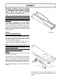
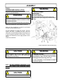
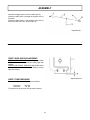
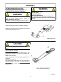
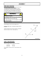
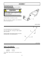
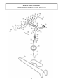
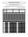
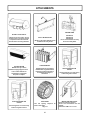
OWNER’S MANUAL
Model Number
700413-3 Subframe
700414-2 Compact Drive Mechanism
700415-2 Northeast Drive Mechanism
Berco
Subframe & Drive Mechanism
for
HUSQVARNA, JONSERED, POULAN, RALLYE, WEEDEATER & YARD PRO
tractors
* ASSEMBLY
* REPAIR PARTS
* OPERATION
* MAINTENANCE
CAUTION:
READ & FOLLOW ALL SAFETY RULES & INSTRUCTIONS BEFORE
OPERATING YOUR EQUIPMENT
104670_EN
*104670_EN*
1
K-06
LIMITED WARRANTY
Owner’s Responsibilities:
Conditions and Products Covered:
BERCOMAC guarantees any part of the product or accessory
manufactured by BERCOMAC and found in the reasonable
judgment of BERCOMAC to be defective in material and or
workmanship will be repaired or replaced by an authorized
dealer without charge up to our maximum labor rates and preestablished times. For replacement parts only standard ground
freight services are covered. This warranty extends to the
original retail purchaser only and is not transferable to any
subsequent purchasers.
BERCOMAC’s defective equipment or part must be returned
to an authorized dealer within the warranty period for repairs.
In the event that defective merchandise must be returned to
manufacturer for repairs, freight fees are prepaid and a written
authorization from BERCOMAC must be obtained by dealer
prior to the shipment. This warranty extends only to
equipment operated under normal conditions. To validate a
warranty claim, it is the user’s responsibility to maintain and
service the unit as specified in the owner’s manual or to have
the unit serviced at their dealer at their expense.
Warranty Period
(from date of the original retail purchase)
General Conditions:
• Residential use: 1 year
• Semi-commercial, professional or rental use: 90 days
Exceptions Noted Below; the following items are guaranteed
by the original manufacturer and have their own warranty,
conditions and limited time:
The sole liability of BERCOMAC with respect to this warranty
shall be strictly and exclusively repair and replacement as
mentioned herein. BERCOMAC shall not have any liability for
any other costs, loss or damage, including but not limited to,
any incidental or consequential loss or damage.
• Tire Chains: 90 days
• Engines: Will vary as per the manufacturer
Please refer to the engine manufacturer’s warranty
statement included with the unit. BERCOMAC is not
authorized to handle warranty adjustments on engines.
In particular, without being limited to, BERCOMAC shall have
no liability or responsibility for:
• Travel time, overtime, after hours time or other
extraordinary repair charges or relating to repairs and or
replacements outside of normal business hours.
• Rental of like or similar replacement equipment during the
period of any, repair or replacement work.
• Any communicating or travel charges.
• Loss or damage to person or property other than that
covered by the terms of this warranty.
• Any claims for lost revenue, lost profit or any similar costs
as a result of damage or repair.
• Attorney’s fees.
Items and Conditions NOT Covered:
This warranty does not cover the following:
• Pick-up or delivery charges or in-home services fees.
• Any damage or deterioration of the unit, parts and or finish
of these due to normal use, wear and tear, or exposure.
• Cost of regular use or maintenance service or parts, such as
gas, oil, lubricants, tune-up parts, and adjustments.
• Any part or accessory which has been altered, modified,
misused, neglected, accidentally damaged or not properly
installed, maintained, stored or repaired not in accordance
with the instructions in the owner’s manual.
• Repair due to normal wear and or any wear items such as
shear pins, bolts, belts, etc.
• Expedited freight fee services for replacement parts.
• Shear bolts and shear pins are to be considered as a
preventive measure not as an assured protection, any
damages resulting from the lack of shear bolts breakage are
not covered.
NOTE: All warranty work must be performed by an authorized
dealer using original (manufacturer) replacement parts.
BERCOMAC’s responsibility in respect to claims is limited to
making the required repairs or replacement without charge up
to our maximum labor rates and pre-established times and no
claim of breach of warranty shall be cause for cancellation or
rescission of the contract of sale of any product or accessory.
This warranty gives you specific legal rights. You may also
have other rights, which vary from state to state.
NOTE: Bercomac reserves the right to change or improve the design of any part or accessory without assuming any obligation to modify
any product previously manufactured.
Instructions for Obtaining Warranty Services:
Contact dealer where equipment was purchased or any other BERCOMAC service dealer to arrange service at their dealership. To
locate a dealer convenient to you, access our website at www.bercomac.com. Don't forget to bring the product and your proof of
purchase (sales receipt) to the BERCOMAC dealer.
Bercomac Limitée
92, Fortin North, Adstock, Quebec, Canada, G0N 1S0
2
TABLE OF CONTENTS
PAGE
INTRODUCTION ...................................................................................................................................................
2
SAFETY PRECAUTIONS .....................................................................................................................................
3
ASSEMBLY
Step 1:
Step 2:
Step 3:
Step 4:
Step 5:
Tractor Preparation ....................................................................................................................
Subframe Installation .................................................................................................................
Drive Mechanism Preparation ...................................................................................................
Drive Mechanism Installation .....................................................................................................
Snowblower Installation .............................................................................................................
Rotary Broom Installation ..........................................................................................................
Blade Installation ........................................................................................................................
5
6
12
16
18
20
22
MAINTENANCE & DISMOUNTING
Maintenance .............................................................................................................................................
Drive Mechanism Dismounting ...............................................................................................................
Belt Replacement .....................................................................................................................................
End of Season Storage ...........................................................................................................................
23
23
23
23
PARTS BREAKDOWN AND LISTS
Compact Drive Mechanism .....................................................................................................................
Northeast Drive Mechanism ....................................................................................................................
Subframe ..................................................................................................................................................
24
26
28
TORQUE SPECIFICATION TABLE .....................................................................................................................
31
ATTACHMENTS ....................................................................................................................................................
32
TROUBLESHOOTING
See attachment owner’s manual for this section. (Snowblower, Blade, Rotary Broom)
1
INTRODUCTION
TO THE PURCHASER
This new accessory was carefully designed to give years of dependable service. This manual has been provided to
assist in the safe operation and servicing of your attachment.
NOTE: All photographs and illustrations in the manual may not necessarily depict the actual models or attachment, but
are intended for reference only and are based on the latest product information available at the time of publication.
Familiarize yourself fully with the safety recommendations and operating procedures before putting the machine to
use. Carefully read, understand and follow these recommendations and insist that they be followed by those who will
use this attachment.
THIS SAFETY ALERT SYMBOL IDENTIFIES AN IMPORTANT SAFETY MESSAGE IN THIS
MANUAL THAT HELPS YOU AND OTHERS AVOID PERSONAL INJURY OR EVEN DEATH.
DANGER, WARNING, AND CAUTION ARE SIGNAL WORDS USED TO IDENTIFY THE LEVEL OF
HAZARD. HOWEVER, REGARDLESS OF THE HAZARD, BE EXTREMELY CAREFUL.
DANGER:
Signals an extreme hazard that will cause serious injury or death if recommended precautions
are not followed.
WARNING:
Signals a hazard that may cause serious injury or death if the recommended precautions are
not followed.
CAUTION:
Signals a hazard that may cause minor or moderate injury if the recommended precautions are
not followed.
Record your attachment serial number and purchase date in the section reserved below (there is no serial number on
the subframe). Your dealer requires this information to give you prompt, efficient service when ordering replacement
parts. Use only genuine parts when replacements are required.
If warranty repairs are required please present this registration booklet and original sales invoice to your selling dealer
for warranty service.
This manual should be kept for future reference.
Please check if you have received all the parts for your kit with the list of the
bag and the list of the box.
SERIAL NUMBER :
___________________________
(IF APPLICABLE)
MODEL NUMBER:
___________________________
PURCHASE DATE :
___________________________
2
SAFETY PRECAUTIONS
Careful operation is your best insurance against an accident. Read this section carefully before operating the vehicle
and accessory. This accessory is capable of amputating hands and feet and throwing objects. Failure to observe the
following safety instructions could result in serious injury. All operators, no matter how experienced they may be,
should read this and other manuals related to the vehicle and accessory before operating. It is the owner's legal
obligation to instruct all operators in safe operation of the accessory.
GLOSSARY:
4. Handle fuel with care, it is highly flammable.
In this manual, right and left sides are determined by
sitting on the seat of the vehicle facing forward.
a) Use approved fuel container.
b) Never add fuel to a running engine or hot engine.
c) Fill fuel tank outdoors with extreme care. Never fill
fuel tank indoors.
d) Never fill containers inside a vehicle, or on a
truck or a trailer bed with a plastic liner. Always
place containers on the ground, away from your
vehicle, before filling.
e) When
practical,
remove
gas-powered
equipment from the truck or trailer and refuel it
on the ground. If this is not possible, then refuel
such equipment on a trailer with a portable
container, rather than from a gasoline
dispenser nozzle.
f) Keep the nozzle in contact with the rim of the
fuel tank or container opening at all times, until
refueling is complete. Do not use a nozzle lockopen device.
g) Replace fuel cap securely and wipe up spilled
fuel.
h) If fuel is spilled on clothing, change clothing
immediately.
In this manual, "accessories" means attachments
(snowblower, rotary broom, blade etc.) that you install
on the vehicle (lawn tractors, A.T.V. s etc).
TRAINING:
This symbol, "Safety Alert Symbol", is used
throughout this manual and on the
accessory’s safety labels to warn of the
possibility of serious injury. Please take
special care in reading and understanding
the safety precautions before operating the
vehicle and accessory.
1. Read this owner's manual carefully. Be thoroughly
familiar with the controls and proper use of the
vehicle and accessory. Know how to stop the unit
and disengage the controls quickly.
2. Never allow children to operate the vehicle nor the
accessory. Never allow adults to operate the vehicle
nor the accessory without proper instructions.
5. Never attempt to make any adjustments while the
engine (motor) is running (except when specifically
recommended by manufacturer).
3. No one should operate the vehicle nor the
accessory while intoxicated or while taking
medication that impairs the senses or reactions.
6. Let the vehicle and accessory adjust to outdoor
temperatures before using.
4. Keep the area of operation clear of all people,
particularly small children and pets.
7.
Never use an accessory without proper guards,
plates, or other safety protective devices in place
PREPARATION:
8.
1. Thoroughly inspect the area where the accessory
is to be used and remove door mats, all foreign
objects and the like.
Always make sure to wear the appropriate safety
equipment required (glasses, muffs, mask…) for
each type of product. See operation section.
9.
Always make sure of having safe traction on the
vehicle by using the recommended accessories
(chains, A.T.V. tracks, counterweights…). See
operation section.
2. For motorized accessories, disengage all clutches
and shift into neutral before starting engine.
10. Never modify the accessory or any part without
the written consent from the manufacturer.
3. Do not operate the accessory without wearing
adequate winter outer garments. Avoid loose fitting
clothing that can get caught in moving parts. Wear
footwear that will improve footing on slippery
surfaces.
3
SAFETY PRECAUTIONS
OPERATION:
1.
13. Keep the accessory away from heat sources or
flames.
Do not put hands or feet near, under or inside rotating
parts.
MAINTENANCE AND STORAGE
1.
When cleaning, repairing or inspecting the vehicle
and accessory, make certain that all moving parts
have stopped. Disconnect wire from the spark
plug(s) and keep wire away to prevent accidental
starting.
2.
Check all the bolts and components at frequent
intervals to make sure that they are properly
tightened.
3.
Never store a motorized accessory with fuel in the
fuel tank inside a building where ignition sources are
present such as hot water and space heaters,
clothes dryers, and the like. Allow the engine to cool
before storing in any enclosure.
4.
Always refer to the owner’s manual when you store
the accessory and vehicle for a prolonged or an
unspecified length of time.
Do not run the engine indoors, except when starting
the engine and for transporting in or out of the
building. Do not operate or let motor run in a storage
area without ventilation because gas contains
carbon monoxide which is odorless, colorless and
can cause death.
5.
Maintain or replace safety and instruction labels, as
necessary.
6
For winter accessories, (if applicable), let the engine
run for a few minutes after clean snow in order to
prevent the rotary parts from freezing.
7.
Never use the accessories across the face of
slopes, go from top to bottom. Exercise extreme
caution when using equipment on slopes. Do not
attempt to clear a steep slope.
7.
Inspect the vehicle’s and accessory’s air filter every
day. Clean it or replace it as necessary. Change the
oil more often when working in dusty conditions.
See the vehicle’s and accessory's owner’s manual.
8.
Never tolerate bystanders in the working zone.
Never use an accessory in the direction of
bystanders, it might throw gravel or debris that can
hurt people or damage property.
9.
Never operate the accessory at high transport
speeds on slippery surfaces. Use care when
backing up.
2.
Exercise extreme caution when operating on or
crossing gravel drives, walks or roads. Stay alert for
hidden hazards or traffic. Do not carry passengers.
3.
After striking a foreign object, stop the engine (motor),
disconnect the wire from the spark plug(s) and keep
wire away to prevent accidental starting. Thoroughly
inspect the accessory for any damage and repair
damage before restarting and using the accessory.
4.
If the unit should start to vibrate abnormally, stop the
engine (motor) and check immediately for the
cause. Vibration is generally a warning of trouble.
5.
Take all possible precautions when leaving the
vehicle unattended. Disengage the power take-off,
lower the attachment, place the transmission into
neutral, set the parking brake, stop the engine and
remove the contact key.
6.
10. Do not carry passengers.
THIS SYMBOL MEANS
DANGER !
BECOME ALERT !
YOUR SAFETY IS INVOLVED !
11. Disengage power to the accessory when it is
transported or not in use.
12. Never operate the accessory without good visibility
or light.
4
ASSEMBLY
IMPORTANT: TORQUE ALL BOLTS ACCORDING
TO TORQUE SPECIFICATION TABLE (SEE TABLE
OF CONTENTS) WHEN STATED: TIGHTEN
FIRMLY. REFER TO PARTS BREAKDOWN
SECTION FOR PARTS IDENTIFICATION.
NOTE: This subframe was designed to fit various
models of tractors. Make sure to follow the
instructions that correspond to your tractor. The
VGT frame sometimes requires a particular
procedure.
This subframe may be used to install different
attachments (see attachments page). Once installed,
it may remain permanently on the tractor. Before
doing any modifications or installations on the tractor,
open the tractor hood, disconnect the headlights and
remove the hood. Disconnect the wire from the spark
plug(s) and keep away from spark plug(s) to prevent
accidental starting.
VGT Frame
STEP 1
TRACTOR PREPARATION:
It is not necessary to remove mower deck at this step.
According to the model of the tractor, remove the mower
front attaching supports if they are bolted to the outside
of the tractor’s frame on each side.
In order to install the subframe’s supports, it may be
necessary to remove certain bolts or certain parts.
NOTE: Take note of the place and how the bolts and
parts were installed in order to reinstall them in the same
manner and place as before.
If applicable, make sure that the belt guide does not
touch any mobile part when reinstalled.
How to:
Take the right support (item 1) and place it on the right
side of the tractor’s frame.
Align the hole (item 2) on the right support with the hole
(item 3) which is about 2” (according to the model of the
tractor) from the edge of the tractor’s front frame.
Remove all the bolts and parts from the tractor’s frame
that will interfere with the installation of the right support.
Do the same operation on the left side with the left
support.
Align the holes in order to identify and remove the
bolts and/or parts that come into interference with the
support
5
ASSEMBLY
STEP 2
SUBFRAME INSTALLATION:
You must choose which brace pin (item 1 or item 4)
that is appropriate for your tractor model.
Tractors with a clutch that measures 5.5”
high only (as shown):
You must use brace pin (item 1) and install it in the
bottom holes of the right support (item 2) with two
carriage bolts 3/8’’ x 1’’ (item 3; heads outside) and
two 3/8" flange nuts.
Tighten firmly.
NOTE: This brace pin must be under the lawnmower
belt.
The belt must not touch the brace pin.
For other tractors:
Use brace pin (item 4) and follow the
installation instructions below.
Install the brace pin (item 4) on the right support (item
2) with two carriage bolts 3/8’’ x 1’’ (item 3;heads
outside) and two 3/8" flange nuts.
Tighten firmly.
NOTE: Generally, the brace pin must be over the
lawnmower belt and at the same time, as low as
possible.
No interference is allowed. See chart below.
Tractor
Hole
(inside view of item 2)
Position of
brace pin
2006 & 2007
(most)
Bottom
Upwards
VGT
frame
Bottom
Downwards
Others
Top
Upwards
or
downwards
Install brace pin
NOTE: On certain models of 2010 tractors, the mower
deck belt may touch the brace pin (item 4), if so,
remove and use the brace pin (item 1) and follow the
instruction at top of page.
6
ASSEMBLY
RIGHT SUPPORT:
Install the right support (item 1) on the right side.
The chart identifies the hardware according to the
holes in the tractor’s frame. Even though some holes
may not exist on certain models of tractors, use the
maximum of holes & bolts possible to ensure the
solidity of the kit.
Carr. B. = Carriage bolt; head towards the inside.
Hex B. = Hexagonal bolt; head towards the outside.
N/A = Not applicable
Item #
If square holes on
tractor
If threaded holes
on tractor
2
Carr. B 3/8 x 3/4’’
Flange nut 3/8’’
Thread cutting
screw 3/8 x 1’’
3
N/A
Thread cutting
screw 3/8 x 1’’
4
N/A
Thread cutting
screw 3/8 x 1’’
5
Carr. B. 5/16 x 1’’
Flange nut 5/16’’
N/A
6
N/A
Thread cutting
screw 5/16 x 1’’
7, 9
Hex B. 3/8 x 1’’
Flange nut 3/8’’
N/A
8
Hex B. 3/8 x 1’’
Flange nut 3/8’’
Thread cutting
screw 3/8 x 1’’
10, 11
N/A
Hex B. 3/8 x 1’’
12
Set screw 5/16 x 1/2’’
(on support for the
cab)
N/A
13
Tractor bolt and
Spacer (Round hole)
N/A
Install right support .
NOTES:
1. On new tractors, turning the wheels to the left will
facilitate installation.
2. The spacer (item 15) is used to strengthen
certain heat shields.
If necessary, slide the shim (item 14) between the
tractor frame (item 16) and the right support; in line
with hole (item 9 or item 11). (Make sure that the shim
stays perpendicular with the top of the support).
Do not tighten the screws or the nuts.
7
ASSEMBLY
LEFT SUPPORT AND HANDLE SUPPORT:
Install the left support (item 1) and the handle support
(item 17). Secure the brace pin (item 19)
The chart identifies the hardware according to the
holes in the tractor’s frame. Even though some holes
may not exist on certain models of tractors, use the
maximum of holes & bolts possible to ensure the
solidity of the kit.
Carr. B. = Carriage bolt; head towards the inside.
Hex B. = Hexagonal bolt; head towards the outside,
except 14 & 16.
N/A = Not applicable.
Item #
If square holes
on tractor
If threaded
holes on tractor
2
Carr. B. 3/8 x 3/4’’
Flange nut 3/8’’
Thread cutting
screw 3/8 x 1’’
3
Hex. B. 3/8 x 1’’
Thread cutting
screw 3/8 x 1’’
4
N/A
Thread cutting
screw 3/8 x 1’’
5
Carr. B. 5/16 x 1’’
Flange nut 5/16’’
N/A
6
N/A
Thread cutting
screw 5/16 x 1’’
7, 9
Hex. bolt 3/8 x 1’’
Flange nut 3/8’’
N/A
8
Hex. bolt 3/8 x 1’’
Flange nut 3/8’’
Thread cutting
screw 3/8 x 1’’
10, 11
Hex. B 3/8 x 1’’
Flange nut 3/8’’
(round holes)
N/A
12
Set screw 5/16 x 1/2’’
(on support for the cab)
N/A
13
Tractor bolt and Spacer
(round holes)
N/A
14, 16
Hex. B 3/8 x 1’’
Flange nut 3/8’’
(round holes)
N/A
18
Plastic grommet
(round hole in support)
N/A
Install the left support and handle support
NOTE:
1. On new tractors, turning the wheels to the right
will facilitate installation .
2. The spacer (item 15) is used to strengthen
certain heat shields.
8
ASSEMBLY
If necessary, slide the shim (item 20, previous page)
between the tractor frame and the support, in line with
hole (item 9 or item 11). (Make sure that the shim
stays perpendicular with the top of the support).
Slightly tighten the screws and bolts.
Make sure that the brace pin stays straight and does
not come into contact with any part of the tractor (ex:
the engine belt when mower deck is in raised
position).
If there is a contact, turn the brace pin upside down.
MOWER BRACKET
If you have removed the original supports from the
tractor, in order to install the mower brackets (item
19) (included in this kit) inside the support; insert two
hex. bolts 3/8 x 1 1/4" (item 20) (the heads on the
outside) in the top holes of the right support .
From the inside of the support, place the shim (item
21; notice orientation) and the mower bracket (item
19) on the bolts. Secure with two flange nuts.
Do the same operation on the left side.
Tighten firmly.
Reinstall the parts:
Reinstall the parts previously removed in their original
position.
Install the mower brackets inside the support and
other parts if applicable.
9
ASSEMBLY
TRACTORS WITH
A
ACTIVATED BY A CABLE:
MANUAL
CLUTCH
If it is not possible to put back in place the tractor’s
belt guides, use the replacement belt guides supplied.
Insert the collars (item 1) on the brace pin (item 4).
Tighten slightly. Place a belt guide (item 2) on each
collar. Secure with a #10 x 24 x 3/4" machine screw
(item 3) and nylon insert lock nut.
The belt guides must not touch the belt (item 5) when
the drive mechanism is engaged.
Install belt guide/drive mechanism engaged
When the drive mechanism is disengaged, the belt
guides (item 6) must push enough on the belt (item 7)
so that the drive mechanism pulley does not turn.
Tighten the collar screws and the nuts tightly.
WARNING
TO PREVENT INJURIES:
It is the person who installs the belt guides
responsibility to make sure that when the
lawnmower is disengaged that all moving parts
stop.
Drive mechanism disengaged
For more information, do not hesitate to contact
the technical support.
10
ASSEMBLY
ASSEMBLY
PIVOT SUPPORT:
Turn the front wheels towards the right.
Install the pivot support (item 1) between the two
supports and slide in place the pin (item 2) in the
required holes. The other holes get the hooked end
(item 5) of the pin. See table.
Tires
Holes in pivot support
15’’ x 6’’ or smaller
Top
16’’ x 6.5’’ or bigger
Bottom
Secure with the hair pin (item 3).
Tighten all the bolts.
If there is interference between the pivot support and
the tractor heat shield, replace with the heat shield
(item 4) supplied.
NOTE: If the original heat shield is bolted to the front
of tractor frame, detach the top part (item 6) of the
heat shield supplied by folding it up and down along
the dotted line.
Be careful not to cut yourself on the sharp edges. For
your safety sand down the sharp edges.
Install the pivot support.
Use the tractor bolts to secure in place.
LIFT ARM:
Insert the nylon bushings (item 1) in the lift arm (item
2).
Install the handgrip (item 3) on the lift arm as shown.
Assemble the lift arm
11
ASSEMBLY
LIFT MECHANISM:
Slide the link (item 1) inside the box of the right
support (item 2). Insert the pin (item 3) inside the link.
Insert the lift arm (item 4) on the pin (item 5) of the
right support and on the pin (item 3).
Secure the arm with one washer (item 6) and one hair
pin 4 mm (item 7).
Secure the pin in place with a flat washer (item 8)
and a hair pin 2.5 mm (item 9, inserted from the
bottom to the top).
Secure the link to the pivot support (item 10) with a
pin (item 11) and a hair pin 2.5 mm (item 12).
Install the lift mechanism
STEP 3
DRIVE MECHANISM PREPARATION:
SUPPORTS-GENERAL INSTALLATION:
Secure the left support (See table) with two carriage
bolts 3/8’’ x 3/4’’ (item 3) heads outside. Secure with
two flange nuts.
NOTE: Install only one support on the right side.
Side
Support
Left
104345
(item 2)
Right
(If no interference with mower deck)
104345
(Item 2)
Right
(If 104345 interferes with mower deck)
104346
(item 1)
On the right side, install the mounting support (item 4)
inside the frame. Install on the outside (according to
chart) the support (item 1 or 2), two washers
7/16" (item 5) and secure with two hair pins (item 6).
NOTE:On certain models of tractors, when the mower
deck is lifted to its highest position, it comes into
contact with the right hand support.
This installation will allow to remove the supports very
easliy at the end of the season.
Install supports (General installation).
12
ASSEMBLY
NOTE: If a bracket is installed on the outside of the
lefthand side of the tractor frame:
1 Install the left support on the inside of the frame.
Secure both bracket and left support to frame using
hardware already mentionned.
2 Insert two flat washers 7/16’’ between the right
support and the frame, but only in this case.
SUPPORTS-VGT FRAME INSTALLATION:
To install the drive mechanism, you must remove the
two bolts from the footrests (from each side).
Secure the left support (item 2) (longest support with
point towards the front) and the right support (item 1)
(shortest support with point towards the front) with the
bolts removed from the footrests.
Install supports (VGT frame)
NOTE:
1) This drive mechanism may be mounted on tractors
with two types of clutch mechanisms. See the
following instructions on the next pages for those
that are appropriate for your tractor.
2) The mower deck must be removed to install / use
the drive mechanism.
NOTE: The drive mechanism must be straight, to
make sure the belt works well.
13
ASSEMBLY
Use the following instructions to reposition the
support (item 1) as needed.
To make the job easier, remove the spring (item 2).
Remove the support (item 1) by removing the two
hex. bolts 1/4’’ x 1/2’’ (item 3).
Tractor
Position
2006 (most models, factory installed)
A
VGT frame
B
Others
C
2007 (most models tractors)
D
Place the support (item 1) in the required position
according to chart, secure with the bolts (item 3 )and
tighten firmly.
Remove and reinstall the spring
NOTE: For position D, use the shim (item 4) and two
1/4 x 3/4" hex bolts supplied in the hardware bag.
Remove the flat pulley (item 5). Turn upside down
and reposition the pulley as shown in A with the flat
washers.
Reinstall the spring (item 2) in its original place.
Reposition the support
Reposition the pulley
14
ASSEMBLY
TRACTOR WITH AN ELECTRIC CLUTCH.
No modifications are needed.
TRACTORS WITH A MANUAL CLUTCH ACTIVATED BY A CABLE.
Remove the spring that is hooked in holes (item1) of
idler arm (item 2) and drive frame (item 10).
Hook the spring of the tractor’s cable (item 5) on the
tension arm.
Cut the tie wrap that holds the cable to the frame.
NOTE: Depending on the mower deck model, there
are different cable lengths. To determine where to
place the cable holder (item 7), hook the end of the
cable spring (item 5) on the idler arm (item 2). Slide
the cable shield (item 6) temporarily into the slot on
the cable holder (item 7). To identify into which
holes the cable holder will be bolted in, you must
apply a slight tension on the cable. This adjustment
must be done with the clutch arm in the disengaged
position.
Remove the cable shield and secure the cable
holder (item 7) on the frame using two 1/4 x 3/4"
hex bolts (item 8) and flange nuts.
Reinstall the cable shield into the cable holder and
secure with a 2mm hair pin (item 9).
Install cable holder
15
ASSEMBLY
STEP 4
DRIVE MECHANISM INSTALLATION:
NOTE: You must remove mower deck to install
the drive mechanism.
Install the drive mechanism (item 1) by hooking the
front part of the drive frame (item 2) on the brace pin
(item 3).
Lift and attach the rear portion of the drive frame
between the supports (items 4 or 5 or 6) by inserting
a pin on each side. Select the correct holes using the
chart.
Support
Holes
Item #
104345 right side
Bottom
4
104346 left side
Top
6
104093 & 104094
Only one possibility
5
Install drive mechanism .
Secure with two 2.5 mm hair pins (item 7).
Install the belt (item 8) on the engine pulley and route
inside the belt guide (item 9).
TRACTOR WITH A MANUAL CLUTCH ACTIVATED
BY A CABLE
Readjust the belt-guides (item 2). If the belt guides
are not installed yet, refer to TRACTOR WITH A
MANUAL CLUTCH ACTIVATED BY A CABLE of
STEP 2
The belt guides (item 2) must not touch the belt (item
1) when the drive mechanism is engaged.
WARNING
TO PREVENT INJURIES:
It is the person who installs the drive mechanism
responsibility to make sure that when the clutch
is disengaged that all moving parts stop.
For more information, do not hesitate to contact
the technical support.
Adjust belt guides/ Drive mechanism engaged
(View of top of drive mechanism)
16
ASSEMBLY
When the drive mechanism is disengaged, the belt
guides (item 4) must push enough on the belt (item 3)
so that the drive mechanism pulley does not turn.
Tighten the collar screw and the nut tightly.
NOTE: After installation, attach the cable to the frame
with the new tie wrap supplied with this kit.
Drive mechanism disengaged
WARNING
TO PREVENT INJURIES DO THIS VERIFICATION
WHEN THE ENGINE IS STOPPED.
BELT ALIGNMENT VERIFICATION:
Make sure the drive mechanism pulley (item 1) is
aligned with the engine pulley (item 2) within 1/4"
If not, you may change the position of the support
(104344) and / or the position of the rear pins as
needed.
If the top edge of the belt touches the edge of the flat
pulley (item 3), remove the flat washer (item 4).
NOTE:Electric Clutch :
If your tractor is equipped with an electric clutch,
make sure the spring is well inserted in its place and
the belt does not touch the belt guides at any point.
NOTE: Manual Clutch:
If your tractor is equipped with a manual clutch, make
sure the belt guide does not touch the belt at any
point while the drive mechanism is engaged.
17
ASSEMBLY
STEP 5
SNOWBLOWER INSTALLATION:
WARNING
Refer to snowblower owner’s manual, parts breakdown
section for parts identification.
TO PREVENT INJURIES:
Stop the motor.
Apply parking brake.
Remove the ignition key.
Disconnect the wire from the spark plug(s) and
keep away from spark plug(s) to prevent accidental
starting.
WARNING
FOR YOUR SECURITY:
Read the snowblower’s owner's manual for safety
precautions and rules.
Follow the assembly and operation instructions.
Attach the snowblower to the subframe as shown.
Make sure the snowblower is pushed in until locked
into place by the springs (item 4).
Lift the snowblower by pulling the lift arm. Turn the
tension arm (item 1) towards the back. Hook the
chain (item 2) (of the helper spring) on the tip (item 3)
of the left support intended for this purpose. Turn the
tension arm towards the front to apply tension on the
spring.
Lower the snowblower.
Install snowblower and lift assist spring
CAUTION
WARNING
The belt tension arm and lift assist spring are
spring loaded & needs to be held firmly while
displacing to prevent injury.
TO PREVENT INJURIES:
It is the person who installs the drive mechanism
responsibility to make sure that when the clutch
is disengaged that all moving parts stop.
For more information, do not hesitate to contact
the technical support.
NOTE: See belt installation instructions in the
maintenance section of the snowblower owner’s
manual.
CAUTION
Never use the snowblower without the belt guard.
18
ASSEMBLY
Insert the handgrip (item 1) on the handle (item 2).
Insert the handle (item 2) through the support (item 3)
as shown.
Insert the handle (item 2) in the rotation worm (item 5)
and secure with a 2.5 mm. hair pin (item 4).
Install handle
VERIFY SKID SHOE ADJUSTMENT:
LEVEL PAVED SURFACE: Adjust skid shoes to allow
3/16" to 1/4" clearance (A) between cutting edge and
surface.
UNEVEN OR GRAVEL SURFACE: Adjust skid shoes
to allow 1/2" to 5/8" clearance (A) between cutting
edge and surface.
Adjust skid shoe
VERIFY TIRE PRESSURE:
Check and adjust tractor tire pressure as follows:
Front tires:
14-15 psi
Back tires:
7-8 psi
Tire pressure must be even on both sides of tractor.
19
ASSEMBLY
ROTARY BROOM INSTALLATION:
WARNING
Refer to rotary broom owner’s manual, parts
breakdown section for parts identification.
TO PREVENT INJURIES:
Stop the motor.
Apply parking brake.
Remove the ignition key.
Disconnect the wire from the spark plug(s) and
keep away from spark plug(s) to prevent accidental
starting.
WARNING
FOR YOUR SECURITY:
Read the Rotary Broom owner's manual for
safety precautions and rules.
Follow the assembly and operation instructions.
Attach the rotary broom to the subframe as shown.
Make sure the rotary broom is pushed in until locked
into place by the springs (item 1).
Install rotary broom
CAUTION
Never use the Rotary Broom without the belt
guard.
BELT INSTALLATION
NOTE: See belt replacement instructions in the
maintenance section of the owner’s manual for the
broom.
Remove the belt guard.
Install the belt on the drive mechanism pulley (item 1)
as shown.
Reinstall the belt guard.
TIP: Because of strong tension on the spring and to
facilitate installation of the belt, the broom must be on
the ground and remove the belt from the engine
pulley.
Item 1: Drive mechanism pulley
Item 2: Rotary broom pulley
Install belt
20
ASSEMBLY
VERIFY BELT ROUTING:
-Lower the rotary broom to the ground and let it run
for a few seconds under supervision.
-Disengage the rotary broom and stop the engine.
-Check the belts to make sure they are well inserted
on the pulleys and have not flipped on their sides in
the pulleys and that they do not touch the belt guides.
WARNING
TO PREVENT INJURIES:
It is the person who installs the drive mechanism
responsibility to make sure that when the clutch is
disengaged that all moving parts stop.
For more information, do not hesitate to contact
the technical support.
Insert handgrip (item 5) on the handle (item 1).
Insert the handle (item 1) through the support (item 2)
as shown.
Install the handle on the control rod (item 3) as shown
and secure with a 2.5 mm. hair pin (item 4).
Install handle
VERIFY TIRE PRESSURE:
Check and adjust tractor tire pressure as follows:
Front tires:
Back tires:
14-15 psi
7-8 psi
Tire pressure must be even on both sides of the
tractor.
21
ASSEMBLY
BLADE INSTALLATION:
Refer to blade owner’s manual, parts breakdown
section for parts identification.
WARNING
FOR YOUR SECURITY:
Read the Blade owner's manual for safety
precautions and rules.
Follow the assembly and operation instructions.
Attach the blade to the subframe as shown.
Make sure the blade is pushed in until locked into
place by the springs (item 1).
Install the blade
Insert the handgrip (item 5) on the handle (item 1).
Insert the handle (item 1) through the handle support
(item 2) as shown.
Install the handle on the control rod (item 3) as shown
and secure with a 2.5 mm hair pin (item 4).
Install handle
VERIFY TIRE PRESSURE:
Check and adjust tractor tire pressure as follows:
Front tires:
Back tires:
14-15 psi
7-8 psi
Tire pressure must be even on both sides of the
tractor.
22
MAINTENANCE & DISMOUNTING
MAINTENANCE
BELT REPLACEMENT
Drive Mechanism Belt:
a) Check mounting bolts at frequent intervals for
proper tightness to be sure equipment is in safe
working condition.
Dismount the drive mechanism.
Remove the bolt which retains the tension pulley.
Replace the belt and re-install the tension pulley.
Before tightening make sure the belt guide does not
touch the belt at any time. Re-install the drive
mechanism.
b) Apply oil at all pivot points.
DRIVE MECHANISM DISMOUNTING
Manual Clutch:
With the engine stopped, engaged and disengage
the clutch and make sure the belt does not come
into contact with the belt guide (104095/104043).
SEE
ATTACHMENT
OWNER'S
MANUAL
(SNOWBLOWER, BROOM AND BLADE) FOR
DISMOUNTING INSTRUCTIONS.
a) Dismount the attachment.
b) Remove the rear counterweight when you remove
the front attachment.
Electric Clutch:
Make sure the belt does not come into contact with
the belt guide (104095/104043)
c) Dismount the drive mechanism by supporting it in
hand and removing the two hair pins and the pins.
Carefully lower to the ground. Remove the V-belt
from engine pulley.
END OF SEASON STORAGE
a) Clean and paint all parts from which paint has
worn.
Manual clutch activated by cable:
Unhook cable shield by removing the hair pin.
Unhook spring. Pull out drive mechanism from
underneath tractor.
b) Apply oil at all pivot points.
d) On certain models of tractors, when the mower
deck is lifted to its highest position, it comes into
contact with the right hand support. Remove the
supports by removing the hair pins and washers.
Store these parts with the drive mecanism for the
next season.
c) Inspect and replace all defective parts before
using again.
e) You may leave the subframe on tractor all year long
or remove it if preferred.
f)
Reinstall mower if needed.
23
PARTS BREAKDOWN
COMPACT DRIVE MECHANISM #700414-2
24
PARTS LIST
COMPACT DRIVE MECHANISM #700414-2
Ref.
Réf.
English description
Description française
Qty.
Qté.
Part #
Pièce #
1 Drive frame
Châssis d'entraînement
1
104343
2 Idler arm
Bras de tension
1
104347
3 Cable holder
Fixation du cable
1
104092
4 Support
Support
1
104344
5 Support
Support
2
104345
6 Belt guide
Guide-courroie
1
104095
7 Right support
Support droit
1
104093
8 Left support
Support gauche
1
104094
9 Flat pulley
Poulie plate
1
102839
10 Flange washer
Rondelle à bride
1
102969
11 Double pulley inc. 102736 & 102782
Poulie double inc. 102736 & 102782
1
102692
12 Sleeve
Douille
1
102782
13 Ball bearing
Roulement à billes
2
102736
14 Stover lock nut 5/8" n.c.
Écrou de blocage 5/8" n.c.
1
O/L
15 Tie wrap 8"
Attache de nylon 8"
1
O/L
16 Hex. bolt 1/4" n.c. x 3/4"
Boulon hex. 1/4" n.c. x 3/4"
4
O/L
17 Flange nut 1/4" n.c.
Écrou à bride 1/4" n.c.
2
O/L
18 Carriage bolt 3/8" n.c. x 2"
Boulon à carrosserie 3/8" n.c. x 2"
1
O/L
19 Nylon insert lock nut 3/8" n.c.
Écrou à garniture de nylon 3/8" n.c.
1
O/L
20 V-Belt B-112
Courroie en V B-112
1
103010
21 Pin
Goupille
2
102189
22 Hair pin 2.5mm
Goupille à ressort 2.5mm
4
102013
23 Right support
Support droit
1
104346
24 Carriage bolt 3/8" n.c. x 3/4"
Boulon à carrosserie 3/8" n.c. x 3/4"
2
O/L
25 Flange nut 3/8" n.c.
Écrou à bride 3/8" n.c.
2
O/L
26 Spring 1/2"
Ressort 1/2"
1
102003
27 Spring
Ressort
1
102304
28 V-Belt A-46
Courroie en V A-46
1
104133
29 Shim
Cale
1
104668
30 Flat washer 7/16" hole
Rondelle plate 7/16" trou
5
O/L
31 Hair pin 2mm
Goupille à ressort 2mm
1
102430
32 Mounting support
Support montage
1
104667
O/L = Obtain Locally
25
PARTS BREAKDOWN
NORTHEAST DRIVE MECHANISM #700415-2
26
PARTS LIST
NORTHEAST DRIVE MECHANISM 700415-2
Ref.
Réf.
English description
Description française
Qty.
Qté.
Part #
Pièce #
1 Drive frame
Châssis d'entraînement
1
104343
2 Idler arm
Bras de tension
1
104347
3 Cable holder
Fixation du câble
1
104092
4 Support
Support
1
104344
5 Support
Support
2
104345
6 Belt guide
Guide-courroie
1
104043
7 Right support
Support droit
1
104093
8 Left support
Support gauche
1
104094
9 Flat pulley
Poulie plate
1
102839
10 Flange washer
Rondelle à bride
1
102969
11 Double pulley inc. 102736 & 103035
Poulie double inc. 102736 & 103035
1
103040
12 Sleeve
Douille
1
103035
13 Ball bearing
Roulement à billes
2
102736
14 Stover lock nut 5/8" n.c.
Écrou de blocage 5/8" n.c.
1
O/L
15 Tie wrap 8"
Attache de nylon 8"
1
O/L
16 Hex. bolt 1/4" n.c. x 3/4"
Boulon hex. 1/4" n.c. x 3/4"
4
O/L
17 Flange nut 1/4" n.c.
Écrou à bride 1/4" n.c.
2
O/L
18 Carriage bolt 3/8" n.c. x 2"
Boulon à carrosserie 3/8" n.c. x 2"
1
O/L
19 Nylon insert lock nut 3/8" n.c.
Écrou à garniture de nylon 3/8" n.c.
1
O/L
20 V-Belt, B-118
Courroie en V, B-118
1
104044
21 V-Belt, A-50
Courroie en V , A-50
1
104104
22 Pin
Goupille
2
102189
23 Hair pin 2.5mm
Goupille à ressort 2.5mm
4
102013
24 Right support
Support droit
1
104346
25 Spring 1/2"
Ressort 1/2"
1
102003
26 Spring
Ressort
1
102304
27 Carriage bolt 3/8" n.c. x 3/4"
Boulon à carrosserie 3/8" n.c. x 3/4"
2
O/L
28 Flange nut 3/8" n.c.
Écrou à bride 3/8" n.c.
2
O/L
29 Shim
Cale
1
104668
30 Flat washer 7/16" hole
Rondelle plate 7/16" trou
5
O/L
31 Hair pin 2mm
Goupille à ressort 2mm
1
102430
32 Mounting support
Support montage
1
104667
O/L = Obtain Locally
27
PARTS BREAKDOWN
SUBFRAME #700413-3
28
PARTS LIST
SUBFRAME #700413-3
Ref.
Réf.
English description
Description française
Qty.
Qté.
Part #
Pièce #
1 Right support
Support droit
1
104332
2 Lift arm
Bras de relevage
1
104336
3 Left support
Support gauche
1
104331
4 Brace pin
Tige de renfort
1
104334
5 Link
Lien
1
104335
6 Pin
Goupille
1
104340
7 Handle support
Support de manivelle
1
104333
8 Pin
Goupille
1
104337
9 Brace pin
Tige de renfort
1
104533
10 Pivot support
Support de pivot
1
104330
11 Handgrip
Poignée de plastique
1
102025
12 Left spring lock
Ressort de barrure gauche
1
102208
13 Right spring lock
Ressort de barrure droit
1
102209
14 Spring bracket
Fixation du ressort
2
102210
15 Handgrip
Poignée
2
102248
16 Plastic grommet
Oeillet de plastique
1
102063
17 Hex. bolt 5/16" n.c. x 1"
Boulon hex. 5/16" n.c. x 1"
2
O/L
18 Flange nut 5/16" n.c.
Écrou à bride 5/16" n.c.
4
O/L
19 Nylon bushing
Coussinet en nylon
2
103087
20 Hair pin 2.5mm
Goupille à ressort 2.5mm
2
102013
21 Pin
Goupille
1
102772
22 Heat shield
Pare-chaleur
1
104669
23 Mower bracket
Fixation de tondeuse
2
103113
24 Hex. bolt 3/8" n.c. x 1 1/4"
Boulon hex. 3/8" n.c. x 1 1/4"
4
O/L
25 Hex. bolt 3/8" n.c. x 1"
Boulon hex. 3/8" n.c. x 1"
8
O/L
O/L = Obtain Locally
29
PARTS LIST
SUBFRAME #700413-3
Ref.
Réf.
English description
Description française
Qty.
Qté.
Part #
Pièce #
26 Flange nut 3/8" n.c.
Écrou à bride 3/8" n.c.
16
O/L
27 Thread cutting screw 3/8" n.c. x 1"
Vis a filetage coupante 3/8" n.c. x 1"
8
O/L
28 Carriage bolt 5/16" n.c. x 1"
Boulon à carrosserie 5/16" n.c. x 1"
2
O/L
29 Carriage bolt 3/8" n.c. x 1"
Boulon à carrosserie 3/8" n.c. x 1"
2
O/L
30 Square head set screw 5/16" n.c. x 1/2"
Vis à pression à tête carrée 5/16" n.c. x 1/2"
2
O/L
31 Hair pin 3mm
Goupille à ressort 3mm
1
102617
32 Hair pin 4mm
Goupille à ressort 4mm
1
102054
33 Washer
Rondelle
1
104339
34 Shim
Cale
2
104120
35 Shim
Cale
2
104121
36 Spacer
Espaceur
2
104091
37 Washer
Rondelle
1
104122
38 Thread cutting screws 5/16" n.c. x 1"
Vis a filetage coupante 5/16" n.c. x 1"
2
O/L
39 Carriage bolt 3/8" n.c. x 3/4"
Boulon à carrosserie 3/8" n.c. x 3/4"
2
O/L
40 Belt guide
Guide-courroie
2
104348
41 Collar
Collet
2
104349
42 Machine screw P.H. #10 x 24 x 3/4"
Vis mécanique P.H. #10 x 24 x 3/4"
2
O/L
43 Nylon insert lock nut #10 x 24
Écrou à garniture de nylon #10 x 24
2
O/L
O/L = Obtain Locally
30
TORQUE SPECIFICATION TABLE
GENERAL TORQUE SPECIFICATION TABLE
USE THE FOLLOWING TORQUES WHEN SPECIAL TORQUES ARE NOT GIVEN
NOTE: These values apply to fasteners as received from supplier, dry or when lubricated with normal oil. They do not
apply if special graphited or moly disulphide greases or other extreme pressure lubricants are used. This applies to
both UNF and UNC threads.
* Thick nuts must be used with grade 8 bolts
SEE Grade No.
BOLT HEAD
IDENTIFICATION
MARKS AS PER GRADE
NOTE MANUFACTURING
MARKS W ILL VARY
BOLT SIZE
Inches
2
5
8*
TORQUE
TORQUE
TORQUE
FOOT POUNDS
Millimetre
Min.
Max.
NEW TON-METERS
Min.
Max.
FOOT POUNDS
Min.
NEW TON-METERS
FOOT POUNDS
NEW TON-METERS
Max.
Min.
Max.
Min. Max.
Max.
Min. Max.
Max.
1/4"
6.35
5
6
6.8
8.13
9
11
12.2
14.9
12
15
16.3
30.3
5/16"
7.94
10
12
13.6
16.3
17
20.5
23.1
27.8
24
29
32.5
39.3
3/8"
9.53
20
23
27.1
31.2
35
42
47.5
57
45
54
61
73.2
7/16"
11.11
30
35
40.7
47.4
54
64
73.2
86.8
70
84
94.9
113.9
1/2"
12.7
45
52
61
70.5
80
96
108.5
130.2
110
132
149.2
179
9/16"
14.29
65
75
88.1
101.6
110
132
149.2
179
160
192
217
260.4
5/8"
15.88
95
105
128.7
142.3
150
180
203.4
244.1
220
264
298.3
358
3/4"
19.05
150
185
203.3
250.7
270
324
366.1
439.3
380
456
515.3
618.3
7/8"
22.23
160
200
216.8
271
400
480
542.4
650.9
600
720
813.6
976.3
25.4
250
300
338.8
406.5
580
696
786.5
943.8
900
1080
1220.4
1464.5
1"
METRIC BOLT TORQUE SPECIFICATIONS
Size Screw
Grade No.
Pitch (mm )
M6
4T
7T
8T
4T
7T
8T
4T
7T
8T
4T
7T
8T
4T
7T
8T
4T
7T
8T
4T
7T
8T
4T
7T
8T
1.00
M8
M10
M12
M14
M16
M18
M20
1.25
1.50
1.75
2.00
2.00
2.00
2.50
COARSE THREAD
Foot Pounds
Newton-Meters
3.6
5.8
7.2
7.2
17
20
20
34
38
28
51
57
49
81
96
67
116
129
88
150
175
108
186
213
-
5.8
9.4
10
14
22
26
25
40
46
34
59
66
56
93
109
77
130
145
100
168
194
130
205
249
4.9
7.9
9.8
9.8
23
27.1
27.1
46.1
51.5
37.9
69.1
77.2
66.4
109.8
130.1
90.8
157.2
174.8
119.2
203.3
237.1
146.3
252
288.6
31
-
7.9
12.7
13.6
19
29.8
35.2
33.9
54.2
62.3
46.1
79.9
89.4
75.9
126
147.7
104.3
176.2
196.5
136
227.6
262.9
176.2
277.8
337.4
Pitch (mm )
FINE THREAD
Foot Pounds
Newton-Meters
-
1.00
1.25
1.25
1.50
1.50
1.50
1.50
12
19
22
20
35
40
31
56
62
52
90
107
69
120
140
100
177
202
132
206
246
-
17
27
31
29
47
52
41
68
75
64
106
124
83
138
158
117
199
231
150
242
289
16.3
25.7
29.8
27.1
47.4
54.2
42
75.9
84
70.5
122
145
93.5
162.6
189.7
136
239.8
273.7
178.9
279.1
333.3
-
23
36.6
42
39.3
63.7
70.5
55.6
92.1
101.6
86.7
143.6
168
112.5
187
214.1
158.5
269.6
313
203.3
327.9
391.6
ATTACHMENTS
ATTACHMENTS
SNOWBLOWER
ROTARY TILLER #700312
Mounts to the rear of lawn, yard &
garden tractors 14 to 25 HP. Comes
complete with drive & manual lift
mechanisms & mounting hardware.
ROTARY BROOM
#700380 with nylon brush
#700381 with polypropylene brush.
Fits on same subframe as
snowblower & utility blade.
Requires an adaptor.
TRACTOR SCREEN CAB
#700424
Universal type fits on a wide variety
of lawn and garden tractors.
UTILITY BLADE #700266
Mounts on the same subframe as the
snowblower & rotary broom.
#700255-40"
#700374-44"
#700378-48"
Fits on same subframe as rotary
broom and utility blade.
COUNTERWEIGHT
#700240 Universal rear weights
#700246 Rear weights Electrolux
Required for safety and traction.
Counterbalances weight of
attachment.
TIRE CHAINS
Two link spacing. Required
traction and safety.
Pkg. of 2
32
for
TRACTOR WINTER CAB
#700423
Universal type fits on a wide variety
of lawn and garden tractors.
WINTER SHELTER #700438
Perfect to protect the tractors,
A.T.Vs and snowmobiles from the
weather.
Dimensions: 5'W x 12'L x 7' 8"H
NOTES
_____________________________________________________________________________________________
_____________________________________________________________________________________________
_____________________________________________________________________________________________
_____________________________________________________________________________________________
_____________________________________________________________________________________________
_____________________________________________________________________________________________
_____________________________________________________________________________________________
_____________________________________________________________________________________________
_____________________________________________________________________________________________
_____________________________________________________________________________________________
_____________________________________________________________________________________________
_____________________________________________________________________________________________
_____________________________________________________________________________________________
_____________________________________________________________________________________________
_____________________________________________________________________________________________
_____________________________________________________________________________________________
_____________________________________________________________________________________________
_____________________________________________________________________________________________
_____________________________________________________________________________________________
_____________________________________________________________________________________________
_____________________________________________________________________________________________
_____________________________________________________________________________________________
_____________________________________________________________________________________________
_____________________________________________________________________________________________
33
BY
WHEN PERFORMANCE
& DEPENDABILITY
ARE NON NEGOTIABLE !
Ber comac Limitée
92, For tin Nor th, Adstock, Quebec, Canada, G0N 1S0
WWW.BERCOMAC.COM
PRINTED IN CANADA
(ORIGINAL NOTICE)
34