1
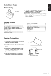
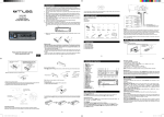
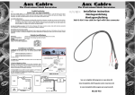
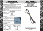
VME 9725 NAV
Installationsanleitung
Installation Guide
®
Lieferumfang
• VME 9725 NAV Receiver
• 2-DIN-Montageklammern für linke und rechte Seite
• 2-DIN-Montagerahmen
• Zierblende
• Anschlusskabel für die Handbremse
• Beutel mit Zubehör
• ISO-Stecker für Lautsprecher
• ISO-Stecker für die Stromversorgung
• Anschlusskabel
• Externes Mikrofon
• Fernbedienung
• Bedienungsanleitung
• Installationsanleitung
Zur Montage des VME 9725 NAV benötigen Sie
die folgende Werkzeuge und Materialien:
• Torx-, Schlitz- und Kreuz-Schraubendreher
• Seitenschneider und Abisolierzange
• Werkzeug zum Herausnehmen des eingebauten
Radios (Schraubendreher, Steckschlüsselsatz oder
andere Werkzeuge)
• Isolierband
• Crimpzange
• Spannungsmesser/Stromprüfer
• Crimpverbindungen
• 18-adriges Anschlusskabel
• 16- bis 18-adriges Lautsprecherkabel
Unterbrechen der Stromversorgung durch die Batterie
Schalten Sie vor der Montage des Geräts die Zündung ab, und lösen Sie das Kabel vom Minuspol (-) der Batterie, um einen
Kurzschluss zu vermeiden
HINWEIS: Wenn das VME 9725 NAV in ein Fahrzeug eingebaut werden soll, das mit einem Navigationssystem ausgestattet ist, lösen
Sie das Batteriekabel nicht. Andernfalls gehen die im Speicher des Navigationssystems abgelegten Daten unter Umständen verloren.
In diesem Fall sollten Sie bei der Montage allerdings besonders vorsichtig sein, um einen Kurzschluss zu vermeiden.
Austauschen der Sicherung
Die Sicherung befindet sich neben dem Anschluss für die Spannungsversorgung. Achten Sie beim Auswechseln der Sicherung darauf,
dass Sie eine neue Sicherung mit 15 A verwenden. Durch den Einsatz einer falschen Sicherung kann das Gerät beschädigt oder ein
Brand verursacht werden.
ISO-DIN-Installation
Dieses Gerät ist für den Einbau in einen 2.0-DIN-Armaturenschacht vorgesehen, der in vielen Importfahrzeugen vorhanden ist. Das
Gerät verfügt auf den Gehäuseseiten über Bohrungen mit Gewinde, die für die Original-Montageklammern mancher Fahrzeuge von
Toyota, Nissan, Mitsubishi, Isuzu, Hyundai und Honda zur Montage des Radios im Armaturenbrett verwendet werden können. Bitte
wenden Sie sich an einen lokalen Fachbetrieb für Stereogeräte für Fahrzeuge, wenn Sie Hilfe bei dieser Montage benötigen.
1. E
ntfernen Sie das Original-Radio aus dem Armaturenbrett bzw. der Mittelkonsole. Bewahren Sie alle Teile und Klammern auf, da
diese für die Montage des neuen Radios erforderlich sind.
2. Bringen Sie die Original-Haltevorrichtungen sowie das Montagezubehör des alten Radios am neuen Radio an.
VORSICHT: Verwenden Sie keine Schrauben, die größer als M5x6 mm sind. Durch längere Schrauben werden unter
Umständen Komponenten im Inneren des Gehäuses berührt und beschädigt.
3. Halten Sie das Radio vor die Öffnung im Armaturenbrett, sodass die
Verkabelung durch das Armaturenbrett geführt werden kann. Beachten
Sie das Schaltbild und stellen Sie sicher, dass alle Verbindungen
mithilfe von Kabelsicherungen oder Isolierband geschützt und isoliert
sind. Wenn die Verkabelung abgeschlossen ist, verbinden Sie die ISOSteckverbinder mit den entsprechenden Anschlüssen auf der Rückseite des
Gehäuses. Schalten Sie das Gerät ein, um die Funktion zu prüfen (die
Zündung des Fahrzeugs muss eingeschaltet sein). Kann das Gerät nicht
eingeschaltet werden, überprüfen Sie die Verkabelung, bis Sie den Fehler
gefunden haben.
4. Montieren Sie das neue Radio im Armaturenbrett oder in der
Mittelkonsole, indem Sie die in Schritt 1 beschriebenen Arbeiten in
umgekehrter Reihenfolge ausführen
ACHTUNG! Achten Sie darauf, dass die Fahrzeugverkabelung nicht
beschädigt wird.
HINWEIS: Der Endbenutzer ist dafür verantwortlich, die Montage und den Betrieb des Geräts entsprechend den Gesetzen der Region
und des Landes sicherzustellen. Das Kabel der HANDBREMSE muss wie in der Bedienungsanleitung angegeben angeschlossen
werden.
ACHTUNG: Die Lüftungsschlitze dürfen nicht verdeckt werden, da das Gerät ansonsten überhitzen und so beschädigt werden kann.
ACHTUNG! Installieren Sie das Gerät so, dass die Fahrsicherheit nicht beeinträchtigt wird.
What’s in the Box
• VME 9725 NAV Head Unit
• Left and Right Double DIN Mounting Brackets
• Double DIN Half Sleeve Install Bracket
• Custom Cosmetic Trim Ring
• Parking Brake Wire
• Hardware Bag
• Speaker Output Harness
• Power Input Harness
• Accessory Harness
• External Microphone
• Remote Control
• Owner’s Manual
• Installation Guide
Tools and Supplies
You will need these tools and supplies to install
your VME 9725 NAV:
• Torx type, flat-head and Philips screwdrivers
• Wire cutters and strippers
• Tools to remove existing radio (screw driver,
socket wrench set or other tools)
• Electrical tape
• Crimping tool
• Volt meter/test light
• Crimp connections
• 18 gauge wire for power connections
• 16 – 18 gauge speaker wire
Disconnecting the Battery
To prevent a short circuit, be sure to turn off the ignition and remove the negative (-) battery cable prior to installation.
NOTE: If the VME 9725 NAV is to be installed in a car equipped with an on-board drive or navigation computer, do not disconnect the
battery cable. If the cable is disconnected, the computer memory may be lost. Under these conditions, use extra caution during
installation to avoid causing a short circuit.
Replacing the Fuse
When replacing the fuse, use a new 15A replacement fuse. Using a fuse with an improper rating could damage the unit and cause a
fire.
ISO-DIN Installation
This unit is designed to fit into a 2.0 DIN dashboard opening, found in many imported cars. The unit has threaded holes in the chassis
side panels which may be used with the original factory mounting brackets of some Toyota, Nissan, Mitsubishi, Isuzu, Hyundai and
Honda vehicles to mount the radio to the dashboard. Please consult with your local car stereo specialty shop for assistance on this type
of installation.
1. R
emove the existing factory radio from the dashboard or center console mounting. Save all hardware and brackets
as they will be used to mount the new radio.
2. Remove the factory mounting brackets and hardware from the existing radio and attach them to the new radio.
CAUTION! Do not exceed M5 X 6MM screw size. Longer screws may damage components inside the chassis.
3. P
lace the radio in front of the dashboard opening so the
wiring can be brought through the mounting sleeve. Follow
the wiring diagram carefully and make certain all connections
are secure and insulated with wire nuts or electrical
tape. After completing the wiring connections, plug the
ISO connectors into the mating sockets on the rear of the
chassis. Turn the unit on to confirm operation (vehicle ignition
switch must be “on”). If the unit does not operate,
re-check all wiring until the problem is corrected.
4. M
ount the new radio assembly to the dashboard or center
console using the reverse procedure in step 1.
CAUTION! Be careful not to damage the car wiring.
NOTE: It is the end-users responsibility to install and operate this unit in a manner in accordance with local, state and federal laws. The
PARKING BRAKE wire MUST BE CONNECTED as directed in the manual.
CAUTION! Do not block the cooling fan exit. If blocked, the unit may overheat and become damaged.
WARNING! Never install this unit where operation and viewing could interfere with safe driving conditions.
Audiovox Audio Produkte GmbH · Lise-Meitner-Str. 9 · 50259 Pulheim / Germany · www.audiovox.de
Cell
RearRight
Front Right
Front Left
RearLeft
SteeringWheelControl (SWC) requires PAC
SWI-PSInterface Adapter (Sold Separately)
M u l t i zo n e L
M u l t i zo n e R
Microphone
ExternalPower Amplifier
Antenna
Auto antenna
control (connect
to antenna control
lead and power
supply of antenna
amplifier)
IMPORTANT: Incorrect wiring connections can damage the unit. Follow the wiring instructions carefully, or have the installation handled by an experienced technician.
For basic iPod connectivity, you can use the white 30-pin to USB iPod cable that came with your Apple device. For iPod video or photo playback, you can use the Audiovox jLink4 cable.
Connect the iPod cable to the rear chassis iPod inputs (USB / 3.5mm connectors) and route the iPod cable to an accessible part of the dash area for easy connectivity. For occasional
iPod use, keep an iPod cable in your glove box and use it to connect the iPod to the front USB connector.
Wiring Diagram