1
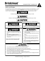
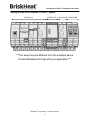
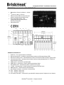
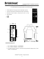
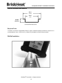
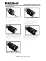
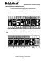
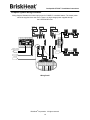
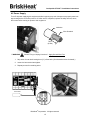
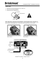
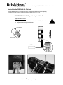
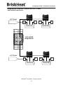
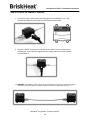
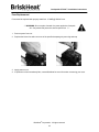
® Centipede 2 ™ Temperature Control System Instruction Manual Instruction Manual Read and understand this material before operating or servicing these heating tapes. Failure to understand how to safely operate these heaters could result in an accident causing serious injury or death. These heaters should only be operated by qualified personnel. ® Centipede2 STACK™ Installation Instructions Table of Contents Important Safety Instructions ......................................................................................................... 3 Introduction ...................................................................................................................................... 4 General Specifications..................................................................................................................... 4 Getting to Know Your Centipede 2® STACK™ System ............................................................... 5 STACK™ Operator Interface: PN: C2STACK-OI .......................................................................... 6 STACK™ Three-Zone Temp Controller: PN: C2STACK-CR ........................................................ 7 STACK™ Power Expansion Unit: PN: C2STACK-EX ................................................................... 8 STACK™ Bridge Expansion Unit: PN: C2STACK-BD .................................................................. 9 DIN-Rail Installation and Removal .................................................................................................. 10 Required Tools .............................................................................................................................. 10 DIN-Rail Installation ....................................................................................................................... 10 DIN-Rail Removal .......................................................................................................................... 12 Space Requirements for Multiple DIN-Rails .................................................................................. 13 Complete System Wiring Schematic .............................................................................................. 13 How to Wire the C2STACK-OI ......................................................................................................... 15 AC Power Supply .......................................................................................................................... 15 Alarm Relay ................................................................................................................................... 16 How to Wire the C2STACK-CR ........................................................................................................ 17 Heating Jacket Power Connection ................................................................................................ 17 Wiring RTD Terminals ................................................................................................................... 18 How to Wire the C2STACK-EX: Optional ....................................................................................... 19 How to Connect the C2STACK-BD: Optional ................................................................................ 20 Bridge Module Connection to Heaters with CAT-5 cables and outside power source.................. 21 How to Connect the C2MOD-C: Optional ....................................................................................... 22 Fuse Replacement ............................................................................................................................ 23 Warranty ............................................................................................................................................ 24 Contact Information ......................................................................................................................... 24 BriskHeat® Corporation. All rights reserved 2 ® Centipede2 STACK™ Installation Instructions Important Safety Instructions SAFETY ALERT SYMBOL The symbol above is used to call your attention to instructions concerning your personal safety. It points out important safety precautions. It means “ATTENTION! Become Alert! Your Personal Safety is involved!” Read the message that follows and be alert to the possibility of personal injury or death. Immediate hazards which WILL result in severe personal injury or death Hazards or unsafe practices which COULD result in severe personal injury or death Hazards or unsafe practices which COULD result in minor personal injury or property damage A person who has not read and understood all operating instructions is not qualified to operate Under operating conditions, screw terminals are considered to have voltage potential Inspect all components before use. Do not use control and heating system if any component is damaged. Do not repair damaged or faulty control and heating systems. Do not crush or apply severe physical stress on any component of system, including cord assembly. Unplug control and heating system when not in use. Failure to observe these warnings may result in personal injury or damage to the Centipede 2® Temperature Control System. Do not immerse or spray any component of the Centipede 2® Temperature Control System with liquid. Keep volatile or combustible material away from control and heating system when in use Keep sharp metal objects away from control and heating system. Failure to observe these warnings may result in electric shock, risk of fire, and personal injury. End User Must Comply to the Following: Only qualified personnel are allowed to connect electrical wiring All electrical wiring must follow local electrical codes and NEC Article 427 Final installation/wiring is to be inspected by the authority who has jurisdiction in the area where the heater and temperature control system are installed The end-user is responsible for providing a suitable disconnect device The end-user is responsible for providing a suitable over-protection device. It is highly recommended that a ground-fault circuit breaker be used BriskHeat® Corporation. All rights reserved 3 ® Centipede2 STACK™ Installation Instructions Introduction The Centipede 2® STACK™ Temperature Control System provides up to 512 zones of temperature control. All components are easily connected together to form a continuous and compact DIN-railed mounted stack for easy installation within a control panel. Power expansion and bridge units are OPTIONAL add-ons to expand the capability of the Centipede 2® STACK™ System. For successful operation of this system, read these instructions prior to use. Features Benefits Individual PID temperature control zones for each heating jacket Precise temperature control throughout system which improves heat uniformity Remote DIN-Rail mounted installation Install Centipede 2 control system in the most ideal place for your application Three control zones per temperature control unit Space-saving and economical Monitors and controls up to 512 heating zones Tool, fab and foundry heating system integration ® General Specifications DIN-Rail Mounted Temperature control range: 0 to 320°C Maximum high limit:325°C Communication Options: Telnet over Ethernet ModBus RTU over RS-232 Command Line over RS-232 Universal Voltage Input: 100-240 VAC up to 15 Amps AC Input Power: No independent power supply is required **** Utilize the proper size gauge conductors and voltage for input power connection. Fuse: 250VAC 15 A rated, mini-fuse (5x20mm), Fast Blow Environmental Temperature: -25 to 55°C (-13 to 131°F) Storage Temperature: -40 to 85°C (-40 to 185°F) Ambient Humidity: 5 to 95% (non-condensing) SAVE THESE INSTRUCTIONS! Additional copies of this manual are available upon request. BriskHeat® Corporation. All rights reserved 4 ® Centipede2 STACK™ Installation Instructions Getting to Know Your Centipede 2® STACK™ System C2STACK-CR C2STACK-EX C2STACK-BD C2STACK-OI ***Your setup may be different from the example above. Contact BriskHeat for help with your application.*** BriskHeat® Corporation. All rights reserved 5 ® Centipede2 STACK™ Installation Instructions STACK™ Operator Interface: PN: C2STACK-OI Dimensions:112mm H x 99mm L x 141mm W (4.4in H x 3.9in L x 5.5in W) Status indicator LEDs for main power and internal / external communication links Dry Contact Alarm Relay - User configurable Normally Open (NO) or Normally Closed (NC) Alarm status LED 5 4 6 7 8 3 141mm (5.5 in) 2 99mm (3.9 in) 1 9 10 112mm (4.4 in) 11 12 13 OPERATOR INTERF ACE 1. 2. 3. 4. 5. 6. 7. 8. 8. 9. 10. 11. 12. RJ45 Port – For communications via Ethernet Ethernet Activity LED – Indicates communications activity over Ethernet (Orange LED) Ethernet Connection LED – Indicates Ethernet cable is connected to RJ45 connector (Green LED) Communication LEDs – Indicates communication mode currently activated (See C2- STACK-OI User Interface for Details) USB Type B – Connector for standard USB USB Type A – Connector for Type A USB Communication Cable Alarm Status LED – Indicates if an alarm is present on any zone +5 VDC – Indicates there is +5VDC present for powering C2STACK units DB9 Connector – Used for Serial communications Alarm Relay Terminals – Connection for Alarm Relay Fuse – 250VAC; 15Amp fuse Fuse – 250VAC; 15Amp fuse AC Voltage Terminals – Connection for grounded AC voltage to power Centipede 2® and heaters BriskHeat® Corporation. All rights reserved 6 ® Centipede2 STACK™ Installation Instructions STACK™ Three-Zone Temp Controller: PN: C2STACK-CR Dimensions:112mm H x 99mm L x 45mm W (4.4” H x 3.9” L x 1.8” W) Three independent zones of PID Temperature Control Up to 5 Amps @ 240VAC per zone Tri-Color LED Status light Solid Green = Zone Operating Correctly Flashing Red = Alarm Condition Flashing Orange = Zone locator feature Flashing Green = Zone Disabled Screw terminals for heater power and temperature sensor input Temperature control range: 0 to 320°C AC Input Power 45mm 4 1 5 2 112mm (4.4 in) 7 3 6 99mm (3.9 in) THREE-ZONE CONTROLLER 1. Zone C RTD Terminals – Connection for 2-wire 100-Ohm RTD 2. Zone B RTD Terminals – Connection for 2-wire 100-Ohm RTD 3. Zone A RTD Terminals – Connection for 2-wire 100-Ohm RTD 4. Zone C Power Terminals – Connection for heater power 5. Zone B Power Terminals – Connection for heater power 6. Zone A Power Terminals – Connection for heater power 7. Zone Status LEDs – Indicate zone status BriskHeat® Corporation. All rights reserved 7 ® Centipede2 STACK™ Installation Instructions STACK™ Power Expansion Unit: PN: C2STACK-EX ****The C2STACK-EX is an optional addition to the C2STACK system**** Provides additional 15 Amp input circuit for added heater capacity Connects to Stack System via DIN-Rail Internal Bus Communication Dimensions:112mm H x 99mm L x 35mm W (4.4” H x 3.9” L x 1.4” W) AC Input Power 35mm (1.4in) 1 2 112mm 3 99mm POWER EXPANSION UNIT 1. Fuse – 250VAC; 15Amp fuse - on C2STACK-EX 2. Fuse – 250VAC; 15Amp fuse - on C2STACK-EX 3. AC Voltage Connection Terminals – Connection point for grounded AC voltage to power C2 and heaters – on C2STACK-EX BriskHeat® Corporation. All rights reserved 8 ® Centipede2 STACK™ Installation Instructions STACK™ Bridge Expansion Unit: PN: C2STACK-BD ****The C2STACK-BD is an optional addition to the C2STACK system**** Expands capability of STACK™ system to incorporate Centipede 2® temperature control modules (C2MOD-C) Includes four RJ-45 Ports to connect up to four different control strings Connect up to 128 Centipede 2® modules Connects to C2STACK System via DIN-Rail and Internal Bus Communication Dimensions: 112mm H x 99mm L x 45mm W (4.4” H x 3.9” L x 1.8” W) 45mm 1.8 in 112mm 4.4 in 1 99mm 3.9 in BRIDGE MODULE UNIT 1. RJ45 Port – For communications to C2MOD-C control modules BriskHeat® Corporation. All rights reserved 9 ® Centipede2 STACK™ Installation Instructions DIN-Rail Installation and Removal 35mm (1.4in) 25mm (1in) 10.5mm (0.413in) Universal DIN-Rail size fits Required Tools To install or remove the Centipede2® STACK™ system, a flathead (slotted) screwdriver is required. It is recommended to use a 3.175mm (1/8”) x 102mm (4”) screwdriver to perform this procedure. DIN-Rail Installation BriskHeat® Corporation. All rights reserved 10 ® Centipede2 STACK™ Installation Instructions DIN-Rail Installation 1. Attach C2STACK-OI to DIN-Rail to lock unit in place (clips latch on underside of unit). Assure unit is locked in place when clips latch on underside of unit. 2. Attach C2STACK-CR Control module to DIN -Rail. Slide Control module to connect to OI unit until firmly connected with the units contacting each other. Continue to add Control Modules until required number of zones have been installed. 3. If required, attach C2STACK-EX module to DIN-Rail and slide to connect to existing Stack components. This is an optional unit. Contact BriskHeat for more information concerning your application. 4. If required, attach C2STACK-BR module to DIN-Rail and slide to connect to existing STACK components. This is an optional unit. Contact BriskHeat for more information concerning your application. 5. Push both ends of the unit together to ensure all connections for modules are made. BriskHeat® Corporation. All rights reserved 11 ® Centipede2 STACK™ Installation Instructions DIN-Rail Removal 2. Separate all C2STACK units, and remove all components before removal of C2STACK-OI. 1. Power down and remove all connections to C2STACK Modules before removing from DIN-Rail. DO NOT Plug or Unplug Live Wires. 3. Use a screwdriver to insert into slot along the bottom of C2STACK Unit. 4. Slide slot out to unlock the C2STACK unit from DIN-Rail. 5. Tilt C2STACK unit away from slot where screwdriver was placed to unlatch from DIN- Rail. BriskHeat® Corporation. All rights reserved 12 ® Centipede2 STACK™ Installation Instructions Space Requirements for Multiple DIN-Rails ****For more information concerning this option contact BriskHeat**** Minimum Requirements for DIN-Rail spacing is 38mm (1.5 in) Cable assemblies are available from BriskHeat to allow for the expansion of more C2STACK units on another DIN-Rail located in close proximity to your existing system. 38mm (1.5in) Minimum Requirements for DIN-Rail spacing is 38mm (1.5in.) Please allow clearance in all directions for the Centipede 2® modules. BriskHeat® Corporation. All rights reserved 13 ® Centipede2 STACK™ Installation Instructions Complete System Wiring Schematic Wiring diagram illustrates the heater input power for C2MOD-C controlled heaters. The heater power should be supplied via a new circuit. There is no high voltage power supplied through the C2STACK-BR units. Heater1C Heater2C Heater1B Heater3C Heater2B Heater3B AC Power M F M F Heater4B Heater4A To Alarm Terminal Normally Open Shown AC Power M F M F AC Power Heater5A Heater1A AC Power Heater2A Heater3A Wiring Detail BriskHeat® Corporation. All rights reserved 14 Heater5B ® Centipede2 STACK™ Installation Instructions AC Power Supply Turn off all power supplying this equipment before beginning any work. Always use a properly rated voltage-sensing device to confirm power is off. After work is completed, replace all safety devices, doors, and covers before turning on power to this equipment. Insulation Wire Stranded 6mm (0.25in) ***WARNING: DO NOT Plug or Unplug Live wires*** Apply Ground Wire First 1. Strip wires of outer shell leaving 6mm (¼”) of bare wire. (See illustration below for details.) 2. Insert wire into terminal and tighten. 3. Repeat process for remaining wires. AC Power BriskHeat® Corporation. All rights reserved 15 ® Centipede2 STACK™ Installation Instructions Alarm Relay 1. Strip wires of outer shell leaving 6mm (1/4”) of bare wire 2. Insert wire into terminal and tighten 3. Repeat process for remaining wires Insulation Wire Stranded 6mm (0.25in) Alarm Latch Feature –This feature is user configurable. The Factory default is ON. If set to ON, an alarm condition will require the user to reset the alarm to return the system to normal condition. Alarm latch is rated for 10 Amps @ 250 VAC. Alarm relay coil will energize with an alarm condition. Normally Open (NO): Will close contacts on alarm condition. Normally Closed (NC): Will open contacts on alarm condition. To Central Monitoring To Alarm Terminal Normally Open Shown BriskHeat® Corporation. All rights reserved 16 ® Centipede2 STACK™ Installation Instructions How to Wire the C2STACK-CR Each C2STACK-CR has the option to connect up to 3 zones of control (Zone A, B, and C). Identify the position of the screw terminals for each zone. Turn off all power supplying this equipment before beginning any work. Always use a properly rated voltage-sensing device to confirm power is off. After work is completed, replace all safety devices, doors, and covers before turning on power to this equipment. ***WARNING: DO NOT Plug or Unplug Live Wires*** Apply Ground Wire First 1. Strip wires of outer shell leaving 6mm (0.25in) of bare wire. (See illustration below for details.) 2. Insert wire into terminal and tighten. 3. Repeat process for remaining wires. Insulation Wire Stranded 6mm (0.25in) Heating Jacket Power Connection Identify the 5 lead wires for a BriskHeat® Centipede 2® Wiring Harness: PN: LX-C2STACK (Note: X identifies length of harness in feet: e.g. L4-C2STACK = 4ft-long wire harness). Contact BriskHeat for information concerning Wiring Harness. 1. Connect first heating jacket wiring harness using a flat-head screwdriver. a. Ground lead to Zone A: G b. Power leads to Zone A: L1 and L2 2. Repeat previous steps for remaining two zones (Zone B and Zone C). BriskHeat® Corporation. All rights reserved 17 ® Centipede2 STACK™ Installation Instructions Wiring RTD Terminals Identify the 5 lead wires for a BriskHeat® Centipede 2® Wiring Harness: PN: LX-C2STACK (Note: X identifies length of harness in feet: e.g. L4-C2STACK = 4ft-long wire harness). ***Contact BriskHeat for information concerning Wiring Harness. Two Blue Color Lead Wires = R1 and R2 (RTD) Heater BriskHeat® Corporation. All rights reserved 18 ® Centipede2 STACK™ Installation Instructions How to Wire the C2STACK-EX: Optional Provides an additional 15-Amp input circuit for connection of additional heater capacity. The C2STACK-EX has three (3) screw terminals for AC Input; L1, G, L2. ***WARNING: DO NOT Plug or Unplug Live Wires*** Apply Ground Wire First 1. Strip wires of outer shell leaving at least 6mm (0.25in) of bare wire. 2. Insert wire into terminal, and tighten. 3. Repeat for remaining wires. Insulation Wire Stranded 6mm (0.25in) AC Power BriskHeat® Corporation. All rights reserved 19 ® Centipede2 STACK™ Installation Instructions How to Connect the C2STACK-BD: Optional The Bridge unit provides communication and low voltage power only ***WARNING: DO NOT use cross over cable. *** Make sure CAT-5 Cable is securely locked in to Centipede Module. Apply pressure to tab to remove from Centipede Module. Plug in CAT-5 Communication cables as required to C2STACK-BD Bridge Module. The number, length, and quantity of the CAT-5 cables are determined by the heating system requirement. The Bridge Unit must be the last unit placed on the C2STACK system. Contact BriskHeat for more information concerning your application. BriskHeat® Corporation. All rights reserved 20 ® Centipede2 STACK™ Installation Instructions Bridge Module Connection to Heaters with CAT-5 Cables and Outside Power Source AC Power M F M F Heater4B Heater4A C2STACK-BD Bridge Module AC Power M F M Heater5A BriskHeat® Corporation. All rights reserved 21 F Heater5B ® Centipede2 STACK™ Installation Instructions How to Connect the C2MOD-C: Optional 1. Connect the 6-pin connector from the heating jacket to the C2MOD-C unit. This connector provides the control power and temperature sensor input. 2. Plug in the CAT-5 connectors on each side of the module. These connections are bi-directional. This connection supplies the low voltage power and communications for the C2MOD-C. ****WARNING: The C2MOD-C unit should not be mounted directly to the heater surface. The module should be connected to power connections between the heaters using plastic tie wraps. **** BriskHeat® Corporation. All rights reserved 22 ® Centipede2 STACK™ Installation Instructions Fuse Replacement Fuse should be replaced with properly rated fuse: 15 AMP @ 250VAC max. ****WARNING: Do not replace fuse with live power applied to Centipede 2®. Only authorized personnel should replace fuse. **** 1. Remove power from unit. 2. Replace the blown fuse with a new one of the specified amperage by removing twist cap. 3. Apply power to unit. 4. If replacement fuse immediately fails, contact BriskHeat for more information concerning your issue. BriskHeat® Corporation. All rights reserved 23 ® Centipede2 STACK™ Installation Instructions Warranty The BriskHeat Corporation (hereinafter referred as (“BriskHeat”) warrants to the original purchaser for the period of eighteen (18) months from date of shipment or twelve (12) months from date of installation, whichever comes first, that the products manufactured by BriskHeat: (A) conform to the description and specifications as set forth in BriskHeat’s current catalogue or in the quotation and drawings submitted by BriskHeat: and (B) are free from defects in materials and workmanship under prescribed use and service. Remedy. BriskHeat’s obligation and the exclusive remedy under this warranty shall be limited to the repair or replacement, at BriskHeat’s option, of any parts of the product which may prove defective under prescribed use and service within eighteen (18) months from date of shipment or twelve (12) months from date of installation, whichever comes first, and which, following BriskHeat’s examination, is determined by BriskHeats to be defective under conditions described herein: provided, BriskHeat has, at its option, a representative of BriskHeat present at start-up. BriskHeat shall not be liable for any incidental, consequential or special damages arising from any breach of warranty, breach of contract, negligence, or any other legal theory, including but not limited to, loss of use of parts or equipment or any associated equipment, cost of capital, cost of any substitute equipment, facilities or services, overhead, downtime costs, or claims of customer of purchaser for such damages. This remedy does not include labor costs for installation or removal of the equipment or parts covered by this warranty, and BriskHeat shall not be responsible for such labor costs. Limitation. This warranty shall not apply to any product or part thereof which has been subject to accident, negligence, alteration, damage during shipment, improper service, abuse, or misuse, including but not limited to use beyond rated capacity. BriskHeat makes no warranty whatsoever with respect to accessories or parts not supplied or manufactured by BriskHeat. BriskHeat’s obligation under this warranty shall be conditioned upon BriskHeat’s receiving written notice of any defect within fifteen (15) days after its discovery, and, at BriskHeat’s option, return of such equipment or parts prepaid to its factory at 1055 Gibbard Ave., Columbus, Ohio 43201. Disclaimer. BRISKHEAT MAKES NO WARRANTY WHATSOEVER, EXPRESS OR IMPLIED, EXCEPT AS IS EXPRESSLY SET FORTH ABOVE. NO AGENT, EMPLOYEE OR REPRESENTATIVE OF BRISKHEAT HAS ANY AUTHORITY TO BIND BRISKHEAT TO ANY AFFIRMATION, REPRESENTATION OR WARRANTY COVERING THE SALE OF ANY PRODUCT, AND UNLESS SUCH AFFIRMATION, REPRESENTATION OR WARRANTY MADE BY AN AGENT, EMPLOYEE OR REPRESENTATIVE IS SPECIFICALLY ENDORSED IN WRITING BY BRISKHEAT, IT SHALL NOT BE ENFORCEABLE BY ANY BUYER. BRISKHEAT MAKES NO EXPRESS OR IMPLIED WARRANTY OF MERCHANTABILITY AND NO EXPRESS OR IMPLIED WARRANTY OF FITNESS FOR PARTICULAR PURPOSE, EXCEPT AS IS EXPRESSLY SET FORTH ABOVE. BRISKHEAT SHALL NOT BE LIABLE FOR CONSEQUENTIAL, INCIDENTAL OR SPECIAL DAMAGES. This warranty allocates risk between the purchaser and BriskHeat as authorized by the Uniform Commercial Code and other applicable law. 1055 Gibbard Ave, Columbus, OH 43201 Toll Free: 800-848-7673 Phone: 614-294-3376 Fax: 614-294-3807 Email: [email protected] BriskHeat® Corporation. All rights reserved 24